Hansol LCD B17BF LCD Monitor User Manual users manual
Hansol LCD Inc. LCD Monitor users manual
users manual

Parts 3
Connection to Computer 4
The range of control Angle 5
Installing Monitor Driver 6
Name and Function of Front 8
Power Management Feature 10
Adjusting OSD 11
Standard Signal Table 17
Specification 18
Troubleshooting 19
Warning 21
Table of Contents
INFORMATION TO USER :
This equipment has been tested and found to comply with the limits of a Class
B digital device, pursuant to Part 15 of the FCC Rules.
These limits are designed to provide reasonable protection against harmful
interference in a residential installation.This equipment generates, uses and can
radiate radio frequency energy and,if not installed and used in accordance with
the instructions, may cause harmful interference to radio communications.
However, there is no guarantee that interference will not occur in a particular
installation; if this equipment does cause harmful interference to radio or
television reception, which can be determined by determined by turning the
equipment off and on, the user is encouraged to try to crrent the interference by
one or more of the fllowing measures:
1. Reorient/Relocate the receiving antenna.
2. Increase the separation between the equipment and receiver.
3. Connect the equipment into an outlet on a circuit difference
from that to which the recerver is connected.
4. Consult the dealer or an experienced radio/TV technician for help.
Shielded interface cable has to be used to ensure product compliance.
CAUTION : Changes or modifications not expressly approved by the
manufacturer responsible for compliance could void the user's
authority to operate the equipment
32
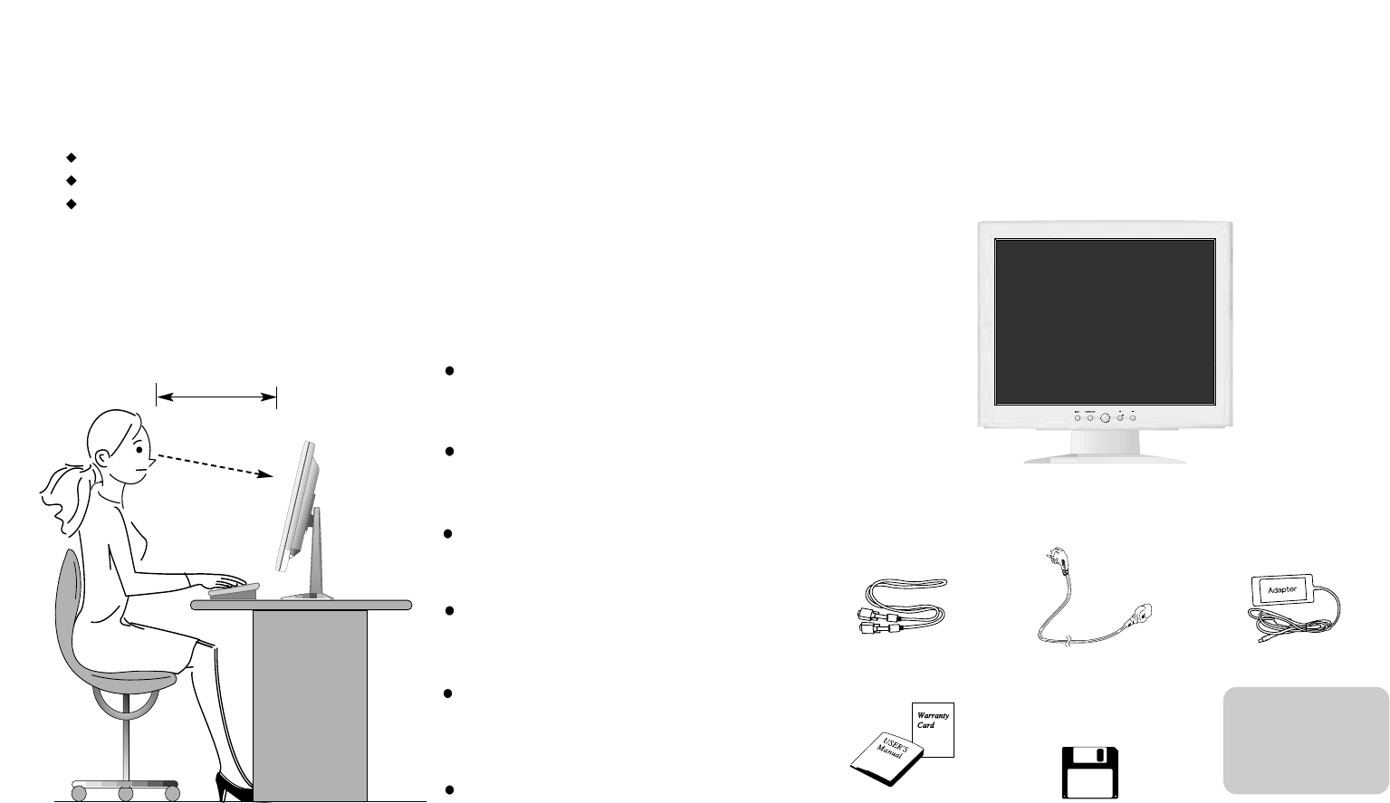
Parts
LCD Monitor
Place the monitor to face the user and then adjust the monitor angle.
Take a break (for about 10 minutes) at every hour during the work with monitor.
Refer to the following figure to take the correct posture.
about 50cm
Look down the monitor
below the horizon.
Relax shoulders and arms,
and sit back on the chair.
Adjust the monitor to
prevent reflection.
Adjust the monitor stand
to acquire required angle.
Keep feet flat on the ground.
Maintain the arms horizontally
and place hands softly on
the keyboard.
Good Posture Guide
12V-DC Adapter
User's Manual /
Warranty Card
Signal Cable AC Power Cable
Installation Disk
Installation Diskette
For use only with
power supply
M
ANUFACTURER
: ILAN
MODEL : F19603A
M
ANUFACTURER
: EDAC
MODEL : EA1050A
5
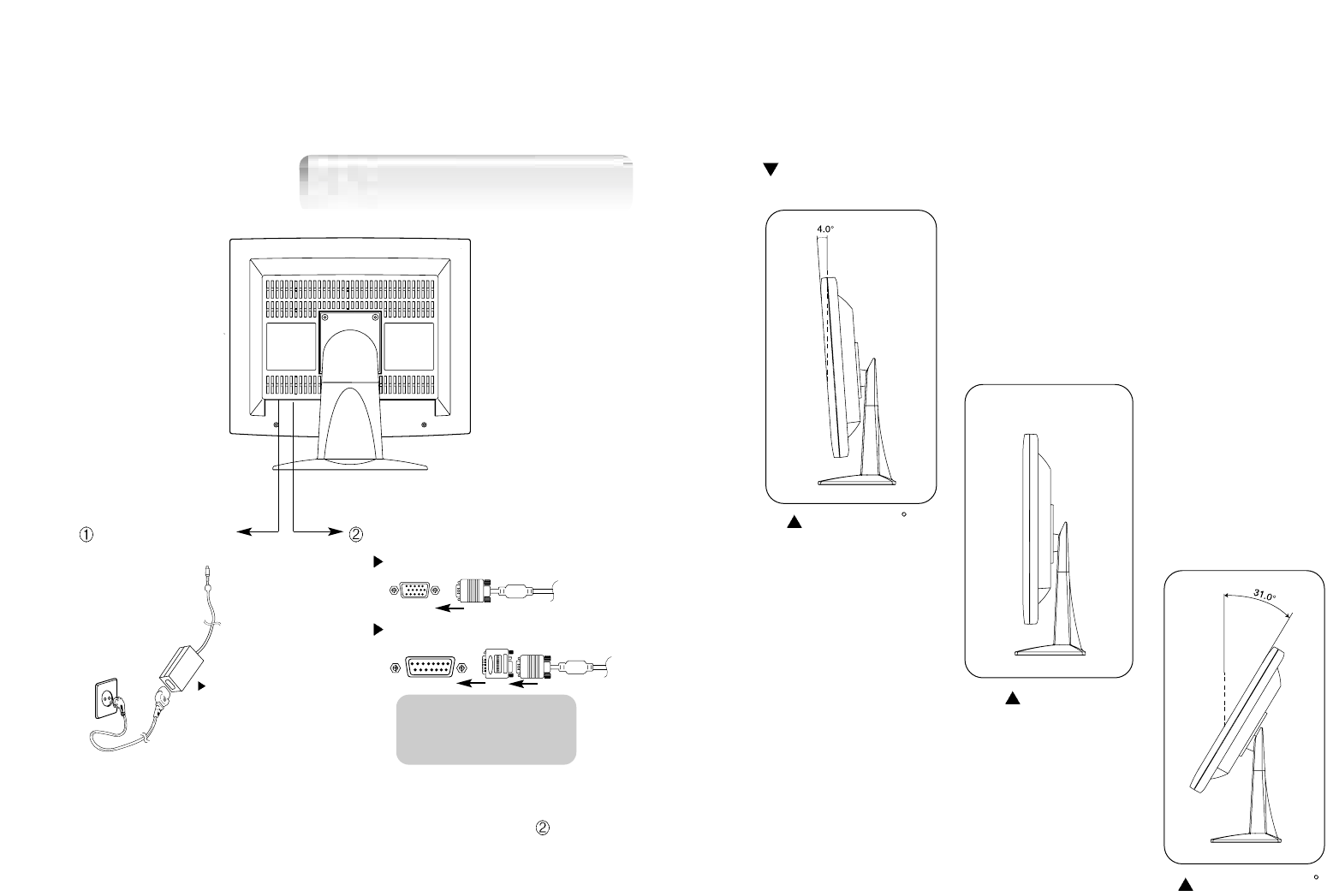
T he range of control Angle
How to Adjust the Stand
4
Connection to Computer
1. Use 220 V or 110 V. (Free Voltage)
2. Connect monitor and computer via computer cable (See figure )
3. Power on the monitor and computer.
4. Connection is finished.
12V DC connection
terminal Computer cable
For PC
For Macintosh
Use adapter.
Adapter for Macintosh (Optional)
Refer to the table on the rear side of
the optional Macintosh adapter and
adjust DIP switch by the resolution.
Forward 4
Default
Backward 31
Basic Connection
76
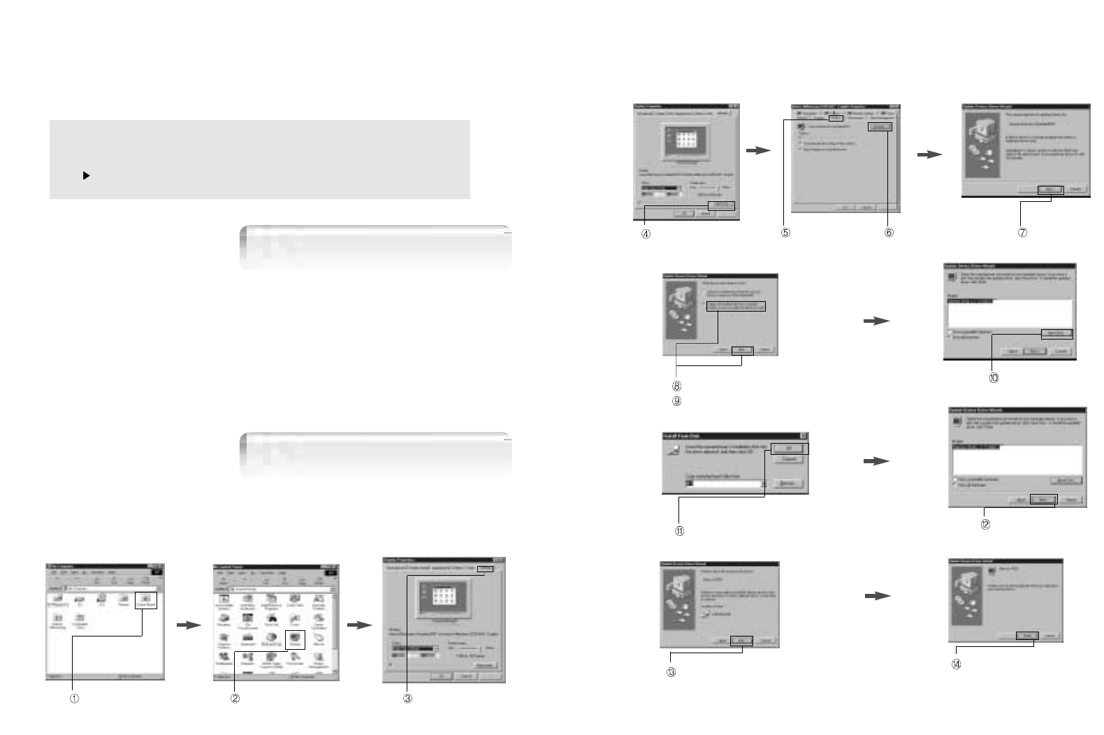
Click 'Finish'.
Click 'Next>'.
Click 'Advanced..'. Click 'Next>'.
Click 'Monitor'. Click 'Change..'.
Click 'Display a list of all...'.
Click 'Next>'.
Click 'Have Disk..'.
Select the driver and click 'OK'. Click 'Next>'.
3. Select "Exit" if the monitor model is changed, and then reboot the Windows.
Installing Monitor Driver
1. Insert the Diskette to the Floppy Diskette driver.
2. Double-click "Install.exe".
3. Select the model(H710) and click "OK" button.
4. Select inf file, and then click "OK" button.
5. Click "Exit" button to close the installation.
Automatic Installation
Manual Installation
1. Insert the Diskette to the Floppy Diskette driver.
2. Click 'My Computer' and follow the procedure below.
Click 'Control Panel'. Click 'Display'. Click 'Settings'.
Run (Click) "Install" at Floppy driver and select the model name to set the
optimum display in Window 95, 98 or 2000.
Use the Driver provided.
98
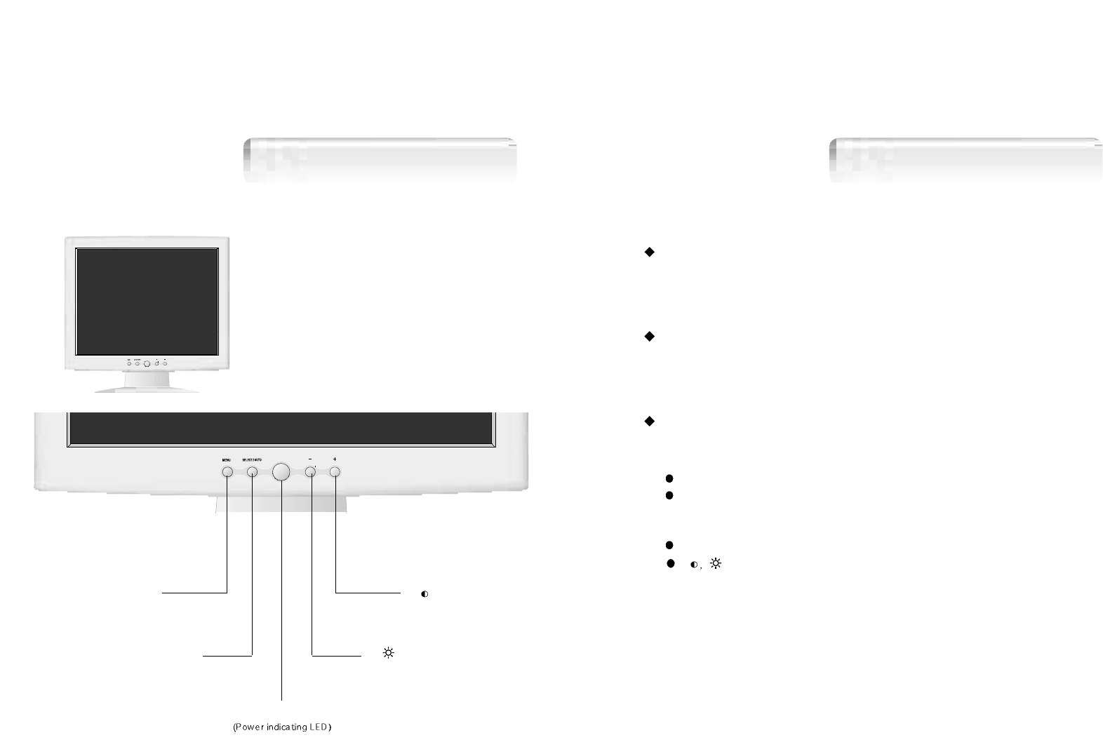
Power button
Power button is located in the lower center of the Front Bezel.
You can push the button to turn on/off the power.
Power Indicating LED
If the green LED in the power switch turns into blinking green,
it indicates the monitor is in power saving mode.
On Screen Display (OSD) Function Button
OSD buttons on the front of bezel perform the following functions.
MENU : Press this button to display menus.
SELECT/ AUTO : Press this button, when OSD is not displayed, to perform
automatic setting.
When OSD is displayed, You can select icons.
POWER : Power button.
: By pressing these button when OSD is displayed, You can move
cursor into the menus which you want.
After press the SELECT button, you can change gauge level or
select sub menus.
When OSD is not displayed, you can adjust brightness or contrast.
Name and Function of Front
Front panel Functions
SELECT/
AUTO BUTTON
MENU BUTTON
+/
BUTTON
BUTTON
POWER BUTTON
+/ -/
-/
1110
No image is displayed with Green blinking.
Monitor is in power saving mode.
Use mouse or keyboard to release power saving mode.
No image is displayed without LED on.
Power cable plug must be pulled out.
Check the power plug on monitor and on the wall.
"Out of range" displayed on the screen.
This message is displayed when the signal from video card exceeds the
maximum frequency of the monitor. Readjust resolution and frequency in
accordance with the monitor capacity. (Refer to Standard Signal Table)
Power Management Feature
When not in use for a long time, the monitor
automatically reduces its power consumption, meeting power saving
standards of EPA and NUTEK.
The monitor is equipped with a power saving circuit that
confirms to the world-standard Display Power Manager Signalling
(DPMS) mode of Video Electronics Standard Association (VESA).
The power management feature requires that the video card of the
computer should support DPMS function.
Status Color of LED Power Consumption
Normal Green Normal Power
DPMS mode Green Blinking
( 2 second interval ) 5 W or Below
Horizontal Position
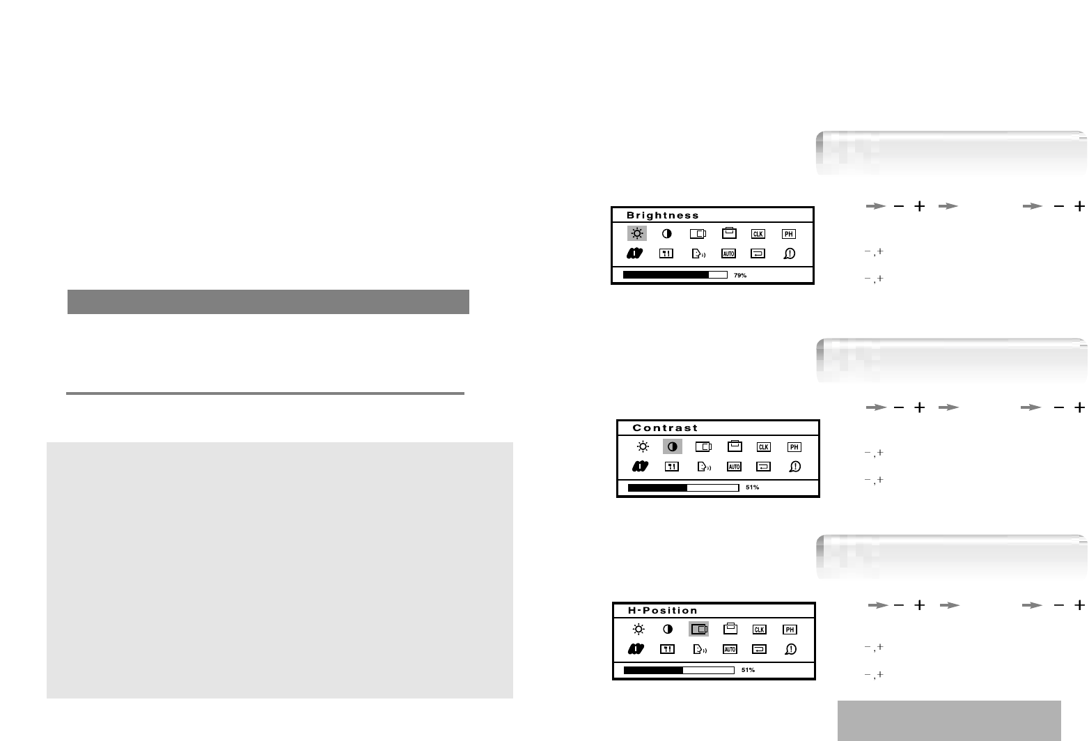
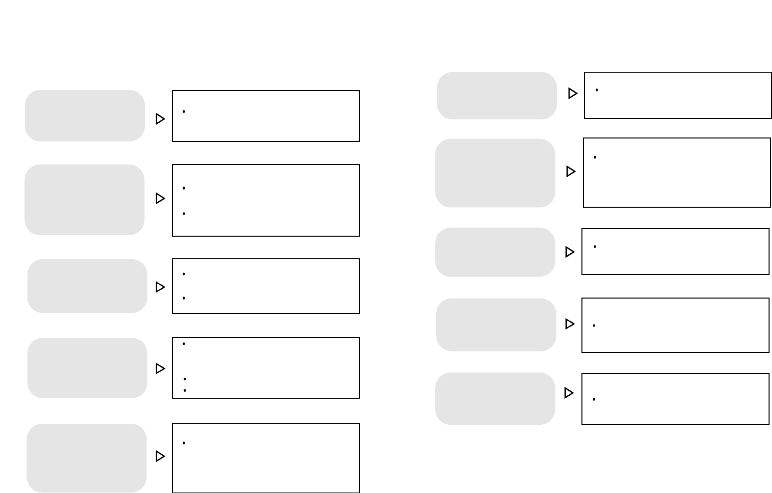
Adjusting OSD
Brightness
Contrast
MENU
1. Press the Menu button.
2. Use to move Brightness ICON.
3. Use SELECT button to select it.
4. Use to adjust the brightness.
5. Use SELECT button to return previously state.
SELECT
MENU SELECT
MENU SELECT
1. Press the Menu button.
2. Use to move Contrast ICON.
3. Use SELECT button to select it.
4. Use to adjust the contrast..
5. Use SELECT button to return previously state.
1. Press the Menu button.
2. Use to move H-Position ICON.
3. Use SELECT button to select it.
4. Use to adjust display left or right.
5. Use SELECT button to return previously state.
According to the characteristic of video card,
control range can be changed.
1312
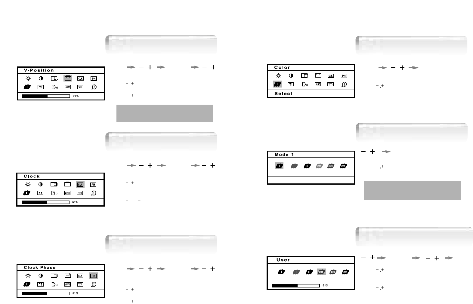
Clock Phase
User Color
1. Press the Menu button.
2. Use to move Color ICON.
3. Use SELECT button into the submenu.
1. Use to move Red, Green, Blue ICON.
2. Use SELECT button to select color what
you want.
3. Use to increase or decrease each color.
4. Use SELECT button to return previously state.
5. Press the Menu button to exit.
1. Use to select the Mode 1,Mode 2,Mode 3.
2. Press the Menu button to exit.
Model 1 : Maximum state of red,green,blue
Model 2 : Bluish white Model 3 : Reddish white
MENU
MENU SELECT
MENU
SELECT
Color
Preset Color
Clock Phase
1. Press the Menu button.
2. Use to move V-Position ICON.
3. Use SELECT button to select it.
4. Use to adjust display upward or downward.
5. Use SELECT button to return previously state.
1. Press the Menu button.
2. Use to move Clock Phase ICON.
3. Use SELECT button to select it.
4. Use to correct fine trembling or Video noise.
5. Use SELECT button to return previously state.
1. Press the Menu button.
2. Use to move Clock ICON.
3. Use SELECT button to select it.
4. If Auto-config function fails to remove Video noise,
Use or
to remove vertical noise.
( Adjusting clock phase is required after the
adjustment of clock.)
5. Use SELECT button to return previously state.
MENU SELECT
MENU SELECT
MENU SELECT
Vertical Position
Clock
Clock Phase
According to the characteristic of video card,
control range can be changed.
1514
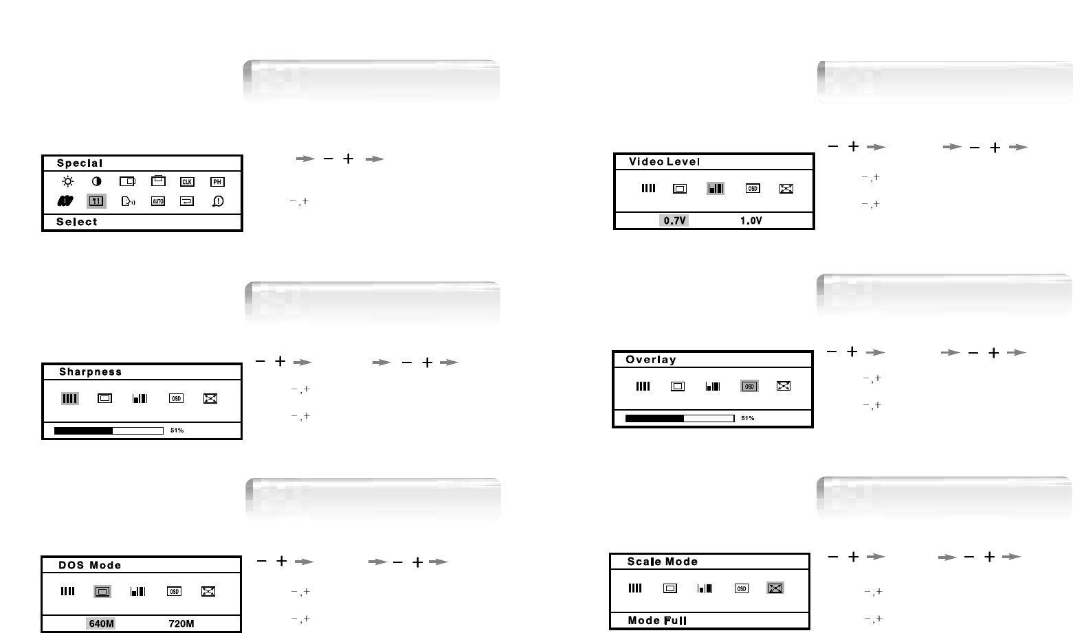
1. Use to move OSD Overlay ICON.
2. Use SELECT button to select it.
3. Use to adjust OSD Overlay.
4. Use SELECT button to return previously state.
5. Press Menu button to exit.
1. Use to move Scale Mode.
2. Use SELECT button to select it.
3. Use to move Mode what you want.
4. Use SELECT button to select it.
SELECT
MENU
SELECT
Scale Mode
OSD OverlayOSD Overlay
1. Use to move Video Level ICON.
2. Use SELECT button to select it.
3. Use to SELET level.
4. Use SELECT button to return previously state.
5. Press the Menu button to exit.
MENU
SELECT
SharpnessVideo Level
1. Use to move Sharpness ICON.
2. Use SELECT button to select it.
3. Use to adjust Sharpness.
4. Use SELECT button to return previously state.
5. Press Menu button to exit.
1. Press the Menu button.
2. Use to move SPECIAL ICON.
3. Use SELECT button into the submenu.
1. Use to move DOS Mode ICON.
2. Use SELECT button to select it.
3. Use to move DOS Mode what you want.
4. Press SELECT button to select it.
MENU SELECT
SELECT
SELECT
MENU
SELECT
DOS Mode
SharpnessSharpness
OSD Overlay
Special
SELECT
1716
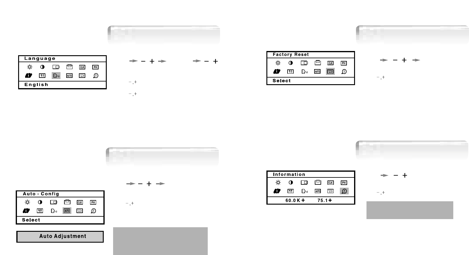
1. Press the Menu button.
2. Use to move the Auto-config ICON.
4. Use SELECT button to readjust the display
condition.
In most case, Auto-Config adjusts display
appropriately. Use PH or adjust CLK
in accordance with graphic card to fine tune
the display.
MENU SELECT
Auto-ConfigAuto-Config
1. Press the Menu button.
2. Use to move the Auto-config ICON.
MENU
Auto-ConfigInformation
1. Press the Menu button.
2. Use to move the Factory Reset ICON.
3. Use SELECT button to return to default setting.
MENU
Auto-ConfigFactory Reset
SELECT
1. Press the Menu button.
2. Use to move Language ICON.
3. Use SELECT button to select it.
4. Use to select language in order.
5. Use SELECT button to return previously state.
MENU SELECT
Language
You can know a display information
(Horizontal, Vertical Frequency)
1918
Type Amorphous active matrix super TFT LCD
Screen Size 43.2cm (Diagonal)
Maximum Resolution
1280 X 1024 @ 75 Hz
Pixel Range
0.264 mm X 0.264 mm
Display Colors 16.7M Color
Contrast Rate 400 : 1
Visual Angle 80° / 80° / 80° / 80° (Left / Right / Up / Down)
Response Speed 40 ms
Brightness 250 cd/m2
Horizontal Frequency 79.9kHz (Max.)
Vertical Frequency 75 Hz (Max.)
Video Signal Analog RGB (0.714 Vpp) 75 ohm
Synchronous Signal Mode H, V Separate TTL Sync,
Maximum 50W
Power Saving Mode Under 5 W
MENU, SELECT/AUTO, POWER,
+/
VESA Standard
Safety Standard UL, CE, TUV, CB
EMI FCC
Low Radiation MPR-II
Size and Weight 420 X192.8 X443.5 / 6.3 Kg
Specification
LCD
Panel
Synchro
nization
Model H710(B17BF
Video
Input
Power
Consumption
Control key
Front Part
Wall Mount
Safety
Standard
& EMI
Dimension
-/
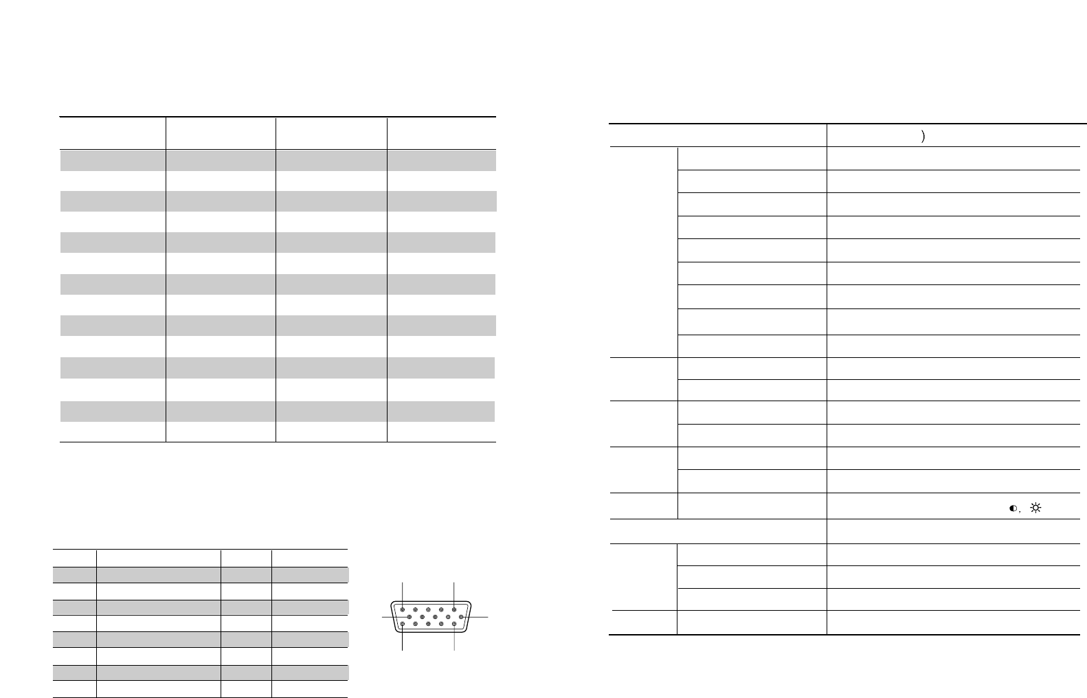
Standard Signal Table
Pin assignment table D-Sub
Mini 15pin connector
15
11 15
610
15pin D-Sub
Pin No. Assignment Pin No. Assignment
1 Red Video 9 N.C
2 Green Video 10 Ground
3 Blue Video 11 Ground
4 N.C 12 SDA
5 Ground 13 H.Sync
6 Red Video Ground 14 V.Sync
7 Green Video Ground 15 SCL
8 Blue Video Ground
VGA (720 X 400)
VGA (640 X 480)
VGA (640 X 480)
VGA (640 X 480)
SVGA (800 X 600)
SVGA (800 X 600)
XGA (1024 X 768)
XGA (1024 X 768)
XGA (1024 X 768)
SXGA (1280 X 1024)
SXGA (1280 X 1024)
MAC (640 X 480)
MAC (832 X 624)
MAC (1152 X 870)
31.469
31.469
37.500
43.269
46.875
53.674
48.363
60.023
68.677
63.981
79.976
35.000
49.726
68.681
70.087
59.940
75.000
85.008
75.000
85.061
60.004
75.029
84.997
60.020
75.025
66.667
74.551
75.062
28.322
25.175
31.500
36.000
49.500
56.250
65.000
78.750
94.500
108.000
135.000
30.240
57.284
100.000
Resolution
Horizontal Frequency
(KHz)
Vertical Frequency
(Hz) Clock Frequency
(MHz)
2120
Check the resolution and frequency of
computer and video card, and set up
again in reference to the current monitor
mode and standard signal mode table.
Double images or
'ghosts'.
Perform Auto-Config.
Adjust COLOR at User Mode in OSD Color
Menu.
Picture is dark.
Picture is biased or cut
or too wide.
Monitor is in power saving mode.
Power LED turns into
amber or amber blinking.
Adjust COLOR at User Mode in OSD Color
Menu.
Color is irregular.
Troubleshooting
Check the power connection.
(Refer to page 4)
Power LED is off.
No picture.
Check the signal cable between monitor
and computer. (Refer to page 4)
Perform Auto_config.
Check the computer connection cable.
(Refer to page 4)
Check the computer power is on.
Message, "No signal."
is displayed on the
screen.
Screen looks to be run
down.
Screen is not clear.
Check the resolution and frequency of
computer and video card, and set up
again refer to the current monitor
mode and standard signal mode table.
Display is unstable and
trembling.
Remove attaches to the signal line
(Video extension cable and others)
and switch on.
Perform Clock and Adjust PHASE.
Switch off/on the monitor.
2322
MemoWarning
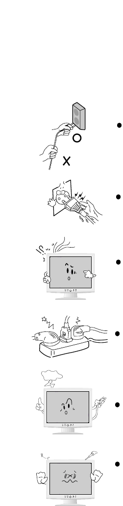
To prevent damage or loss, please read this warning carefully.
When connecting/disconnecting the plug, pull out
the plug itself, and never pull the cord to prevent fire
caused by short.
To prevent electric shock, do not connect/dis-
connect the plug with wet hand.
To prevent fire, do not connect a large number of
equipments in a single line.
To prevent fire and electric shock, pull out the plug in
case of thunder and lightening.
To prevent fire and electric shock, do not try to take
the monitor apart or repair it yourself. Contact your
local service station or customer service center for
inspection, modification or repair.
If you see smoke or smell something burning, stop
using the unit, switch off the power, pull out the plug,
and then contact your local service station.