Hanwang Technology FACEID-MX000 Facial Recognition Terminal User Manual
Hanwang Technology Co., Ltd Facial Recognition Terminal Users Manual
Users Manual

Confidential Page 1
M2000 Facial Recognition
Terminal
User Manual
Original operating instructions Version 1.1 / 12-2014 EN

Confidential Page 2
General Notice
Although every care has been taken to ensure that this manual is reliable and accurate,
Hanvon Corporation (here after referred to as Hanvon) provides it „as is‟ and without
express, implied, or limited warranty of any kind. In no event shall Hanvon be liable for
any loss or damage caused by the use of this manual.
This manual describes M2000 facial recognition terminal
in detail and contains full operating instructions.
Hanvon reserves the rights to change the specifications and information in this document
without notice. The information contained herein is proprietary to Hanvon. Release to thir
d parties of this publication or of information contained herein is prohibited without the pri
or written consent of Hanvon.
Copyright © Hanvon, 2014

Confidential Page 3
Content
1. About this document ....................................................... 4
2. Product Features ............................................................. 5
2.1 Appearance View ............................................................... 5
2.2 Installation Guide ............................................................... 7
2.3 Connection Port ................................................................. 8
2.4 Power up terminal .............................................................. 9
3. Operating Guide ............................................................. 10
3.1 Admin. Management ........................................................ 10
3.2 User Management ........................................................... 13
3.3 Data Management ........................................................... 16
3.4 USB Management ........................................................... 18
3.5 System Settings ............................................................... 21
3.6 System Info. ..................................................................... 30
3.7 Auto Test ......................................................................... 31
4. Appendix ......................................................................... 33
Appendix1. Product Specification................................... 33
Appendix2. Caution .......................................................... 34

Confidential Page 4
0. About this document
Validity
These instructions are valid for the M2000 Facial Recognition Terminal.
Target group
The target group for this document comprises the terminal operator and technical
personnel.
Content and purpose
These user manual describe the M2000 facial recognition terminal installation and
operation information to users.
Supplementary documents
N/A
Abbreviations
Hanvon Hanwang Technology Co., Ltd Brand
Face ID Hanwang Technology Co., Ltd Brand
M2000 M2000 Facial Recognition Terminal
Danger categories and warning symbols
DANGER
Danger Operation!
NOTE
Application tips, useful information
Confidential Page 5
1. Product Features
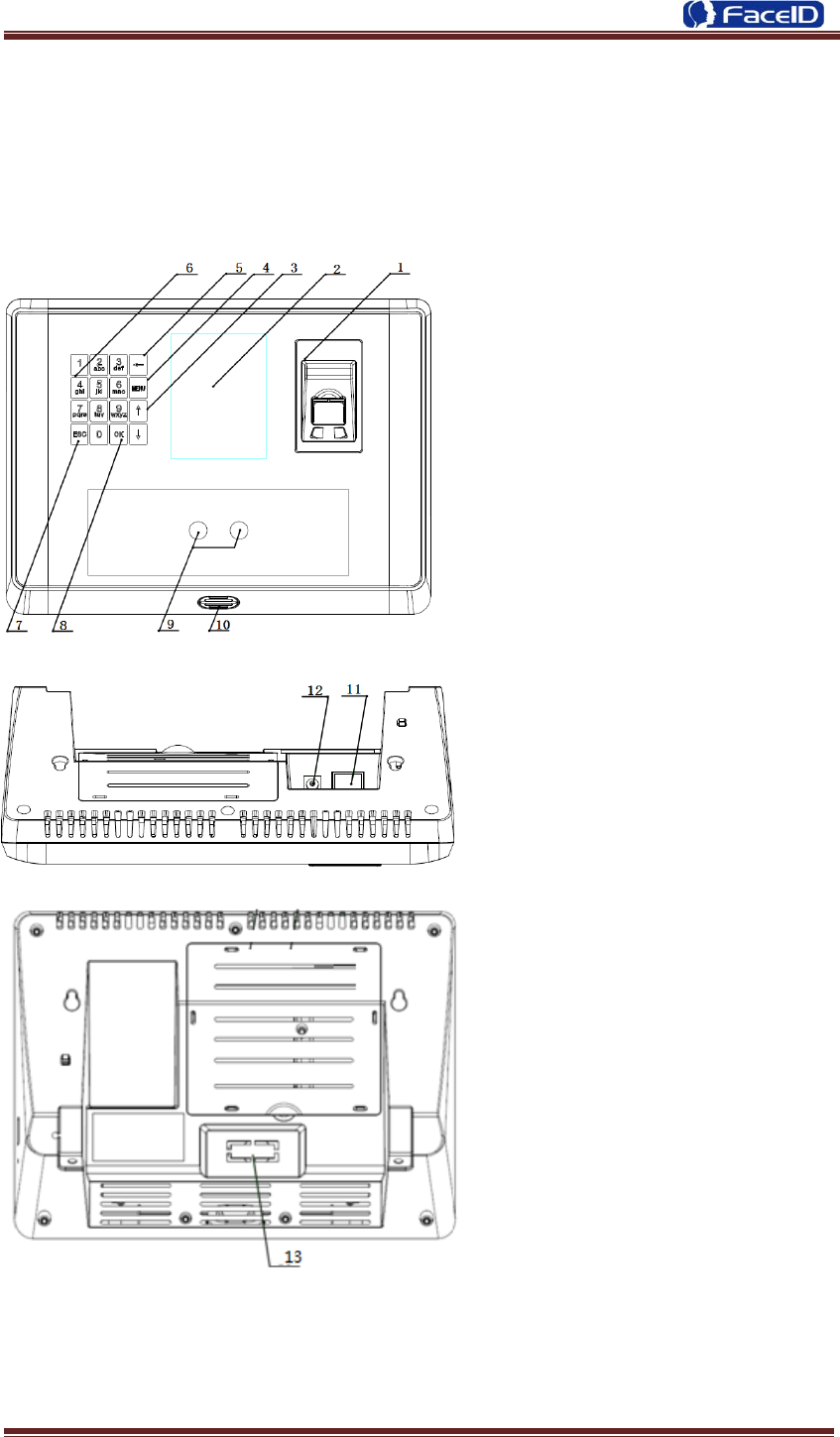
2.1 Appearance View
1. Fingerprint Reader
2. Display
3. Button: Previous or next field
4. Button: Main function menu
5. Button: Backspace and delete
6. Button: Digital Keypad
7. Button: Cancel button
8. Button: Confirm button
9. Camera
10. Loudspeaker
11. Power Adaptor Port
12. Network Cable Port
13. Connection Port

Confidential Page 6
14. USB Socket(Just for data transmission)
15. Reset Button
Confidential Page 7
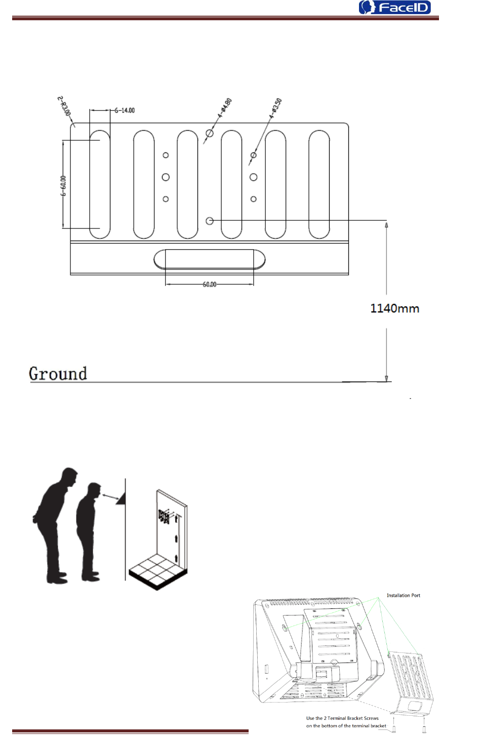
2.2 Installation Guide
User can drill the holes according to the
mounting diagram. Use the 4 wall mount,
screws to mount the bracket to the wall.
User also could mount the terminal by
choosing your “shortest” users and have
them stand in front of the device.
Hold the terminal on the wall that
employee can comfortably center their
face in the LCD display window.
Use the 2 bracket screws on the bottom of the
bracket. Align the terminal with the pairs on
the mounting-plate and secure the two
together with the 2 Philips head screws. Be
careful not to pinch the AC cord. When
finished, plug the Power Adapter into the AC
wall outlet.
Confidential Page 8
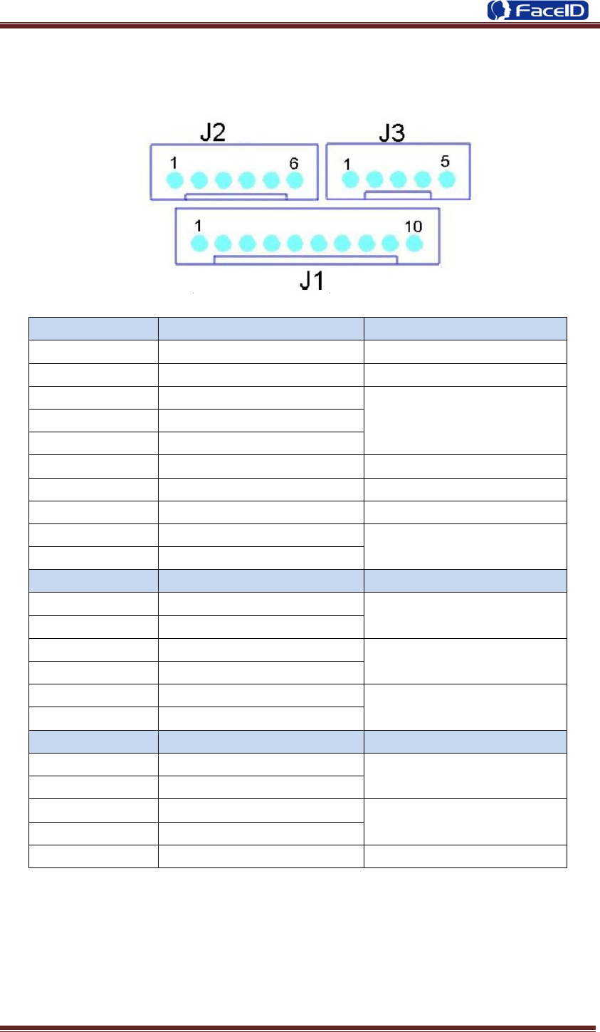
2.3 Connection Port
PIN
Definition
Feature
J1.1
VC12V
12V Power Supply
J1.2
GND
Ground
J1.3
LOCK_NO
Door Lock
J1.4
LOCK_COM
J1.5
LOCK_NC
J1.6
DOORSENSOR
Door Magnetic Detection
J1.7
GND
Ground
J1.8
DOORSWITCH
Door Switch
J1.9
COM 2
Alarm/Bell Output
J1.10
NO 2
PIN
Definition
Feature
J2.1
WGD0_IN
Weigand Input(Need
Customized)
J2.2
WGD1_IN
J2.3
GND
Ground
J2.4
GND
J2.5
SPK+
Audio Output
J2.6
SPK-
PIN
Definition
Feature
J3.1
WGD0_OUT
Weigand Output
J3.2
WGD1_OUT
J3.3
GND
Ground
J3.4
GND
J3.5
BEEP
Buzzer

Confidential Page 9
2.4 Power up terminal
Select a proper language when the terminal boot first time. The terminal will provide
several language options for customers:
English
Spanish
Korean
Turkish
Japanese
┉┉
Confidential Page 10
2. Operating Guide
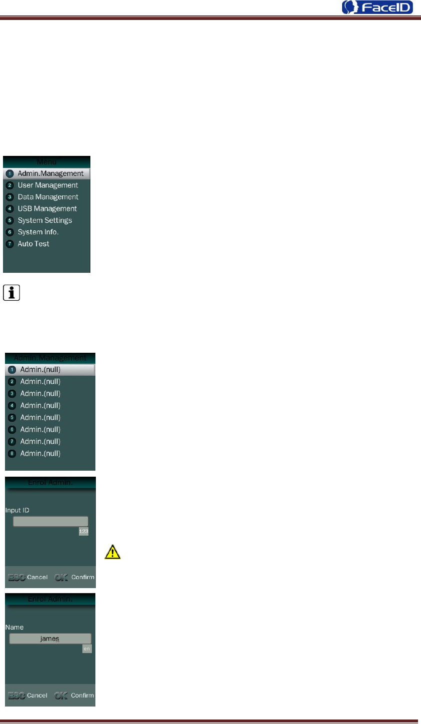
3.1 Admin. Management
Admin. Management Main Menu
If no admin. in system, then press <MENU> to enter the main
menu.
If there has enrolled admin. in system, then press <MENU> to
enter admin. verifying process. While the verification is correct, then
the system enter to the main menu.
Press <↑/↓>to move selection to <Set Admin>, and press <OK>
to enter into admin. menu.
Press 1-7 digital buttons on the keypad to enter the corresponding functions
directly.
Set Admin.
There are total 8 admin. accounts. A <Null Admin.> sign will
display for unset admin. accounts. Choose a <Null> account to
register an admin.
Input Admin. ID: Input an ID for admin. If the ID is in the
database, then the terminal displays admin.‟s name.
Admin ID uses natural sequence numbers.
Admin.ID can‟t be duplicated and start with “0”.
Input Admin. Name: Press <MENU> to switch character
inputting mode between <Upper Case>, <Lower Case> and
<Digital>.
Confidential Page 11
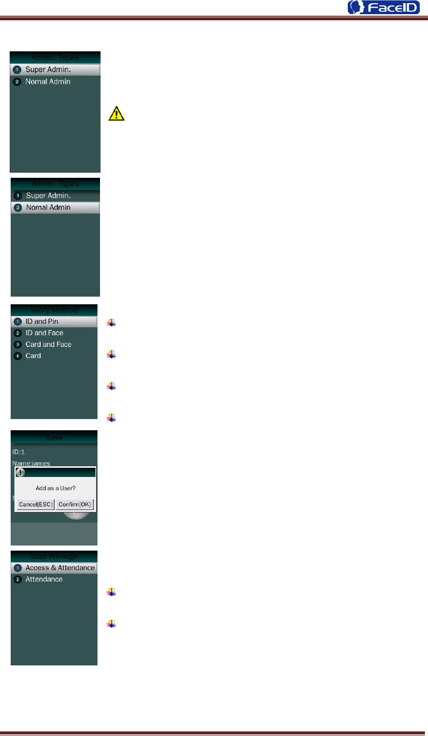
Admin. Types
Super Admin. can operate all functions and normal
administrators.
The first administrator must be super admin and can‟t be
deleted in system.
Normal Admin. can operate User/Data/USB Management
function, check system info. and auto test function.
Verification modes:
ID and Pin: Use ID and password sequentially as a verification
method.
ID and Face: Use ID and face sequentially as a verification
method.
Card and Face: Use card and face sequentially as a
verification method.
Card: Use card as a verification method.
Add as an User: Press [OK] to make the admin. as an user. If
don’t, please check [ESC].
If add as an user, please select the user privilege mode:
Access & Attendance: The terminal is used for access
control and time attendance with relay output.
Attendance: The terminal is only used for time attendance
without relay output.
Confidential Page 12
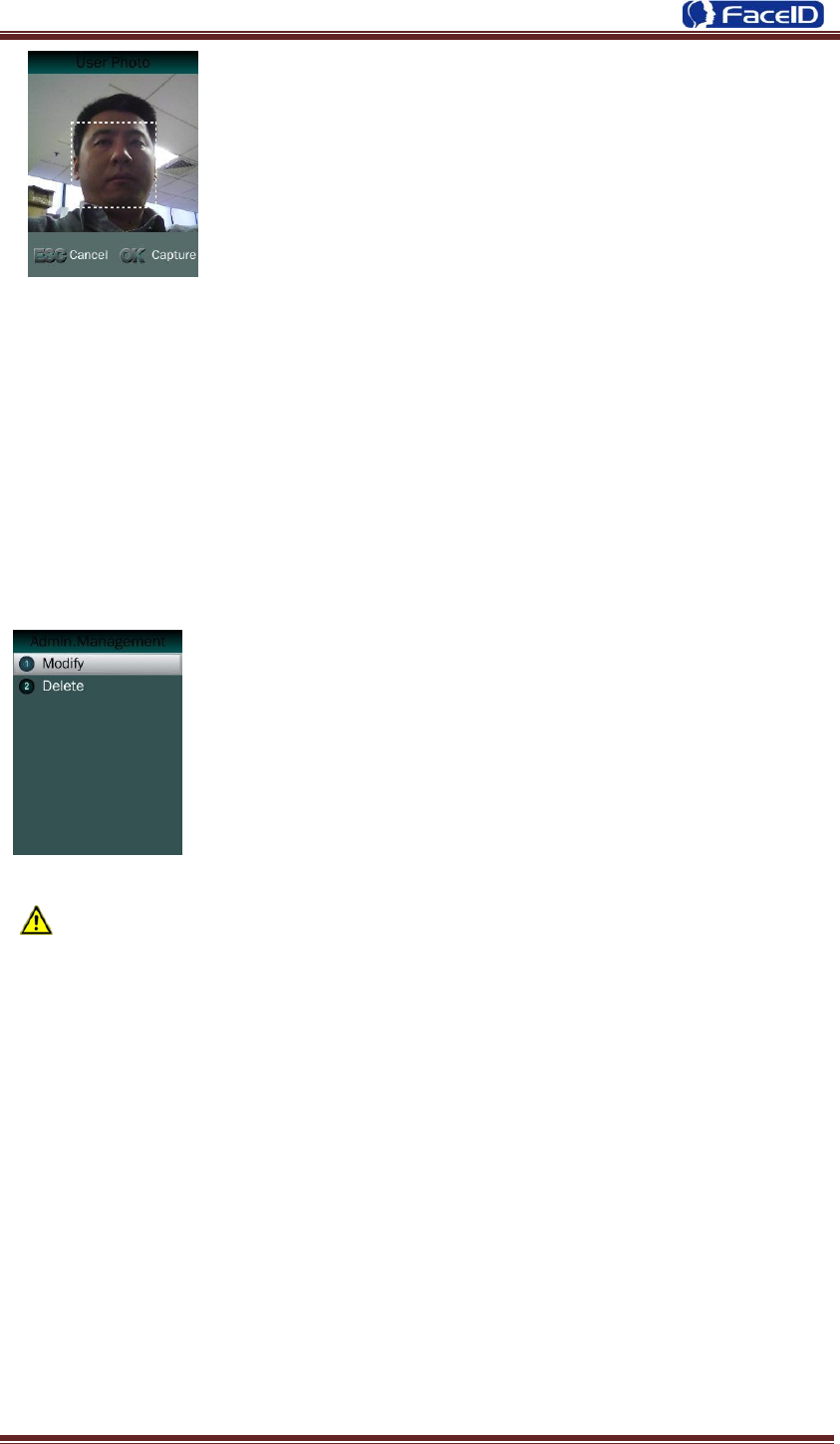
User Photo: Press [OK] to capture a photo for the user. If don‟t,
please check [ESC].
Admin Verification
After set an admin. account, then press <MENU> to activate admin verification
process.
Input admin. ID (or using registered RFID card)
Input corresponding password or using face verification, according to the mode
during admin registration, after verification is successful, then the system enter to the
main menu.
Modify & Delete Admin account
Select a registered admin. account to modify or delete this
account.
Modify admin. name
Change verification mode:
Modify password
Re-enroll face template
Re-register RFID card
Delete the certain admin. account: If only one registered admin. account with in
the system, then it will be banned to delete.
Confidential Page 13
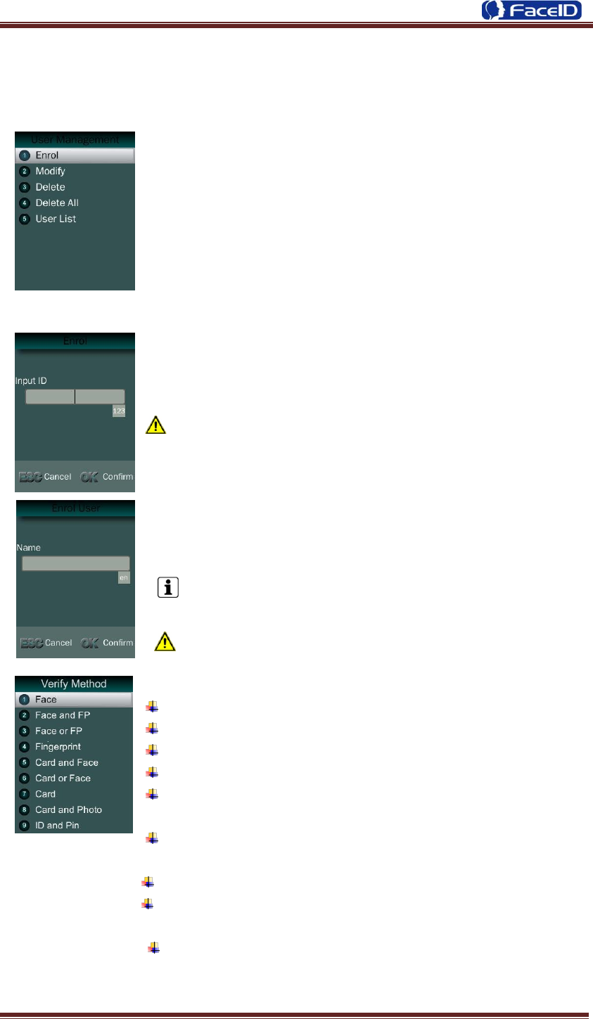
3.2 User Management
User Management Main Menu
User Enroll
Input User ID
The range of User ID is from 1-99,999,999,999,999.
Input name
Press to <MENU> will switch character inputing mode
between <Upper Case> <Lower Case> and <Digital>.
User Name can contain 18-bit characters totally.
Select a verification mode
Face: Use face as a verification method.
Face and FP: Use face and fingerprint as a verification method
Face or FP: Use face or fingerprint as a verification method
Fingerprint: Use fingerprint as a verification method
Card and Face: Use card and face sequentially as a
verification method.
Card or Face: Use card or face separately as a verification
method.
Card: Use card as a verification method.
Card and Photo: Use card as a verification method, and takes
a picture after successful verification.
ID and Pin: Use ID and password sequentially as a
verification method.
Confidential Page 14
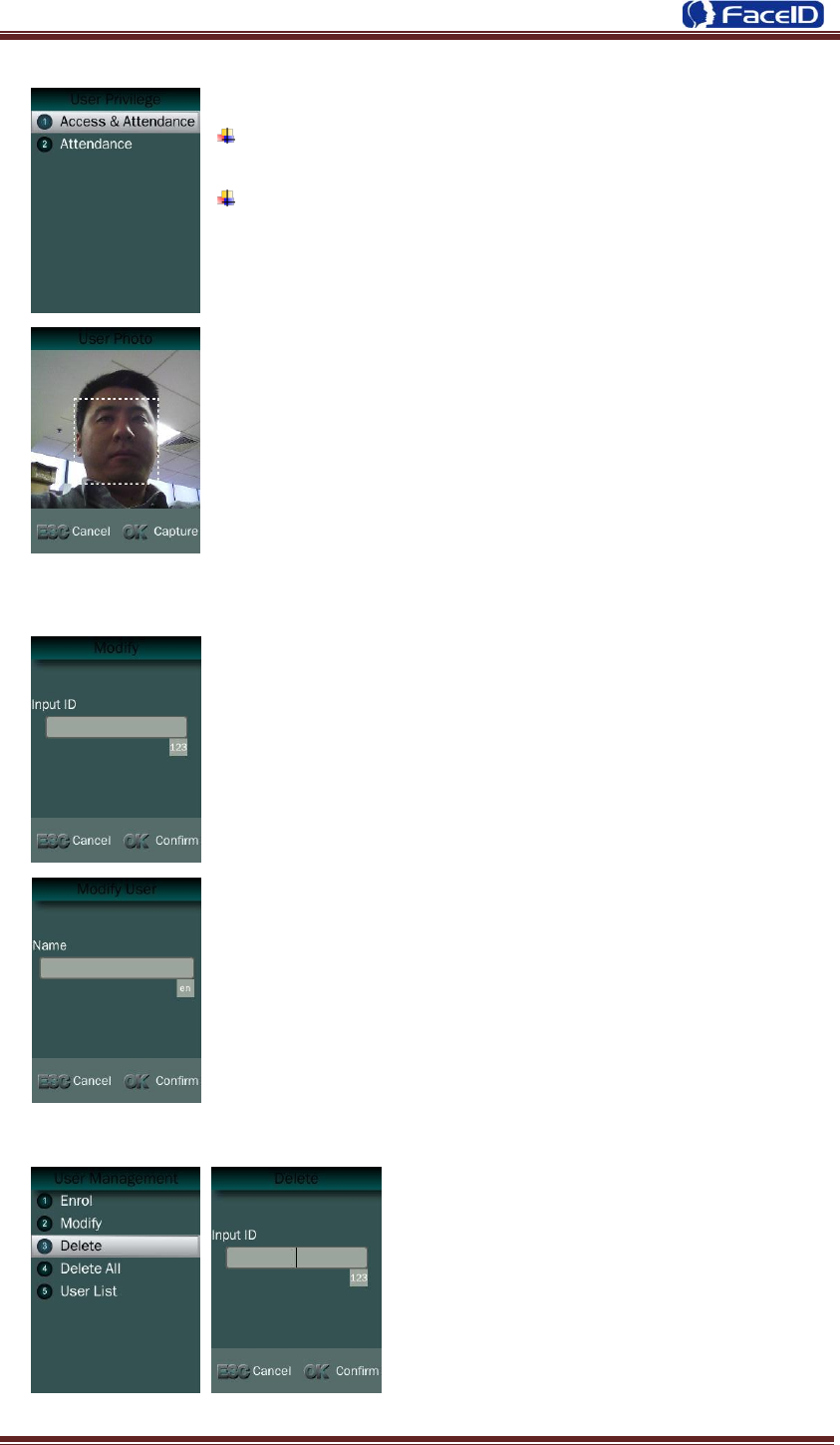
Select a privilege
Access & Attendance: The terminal is used for access
control and time attendance with relay output.
Attendance: The terminal is only used for time attendance
without relay output.
User Photo: Press [OK] to capture a photo for the user. If
don‟t, please check [ESC].
User registering finished.
Modify User
Input User ID
Following the procedure to change <user name>,
<verification mode> and <privilege>.
Delete User
Input an User ID
Press [OK] (or [ESC]) to confirm (or
cancel) this process.
Confidential Page 15
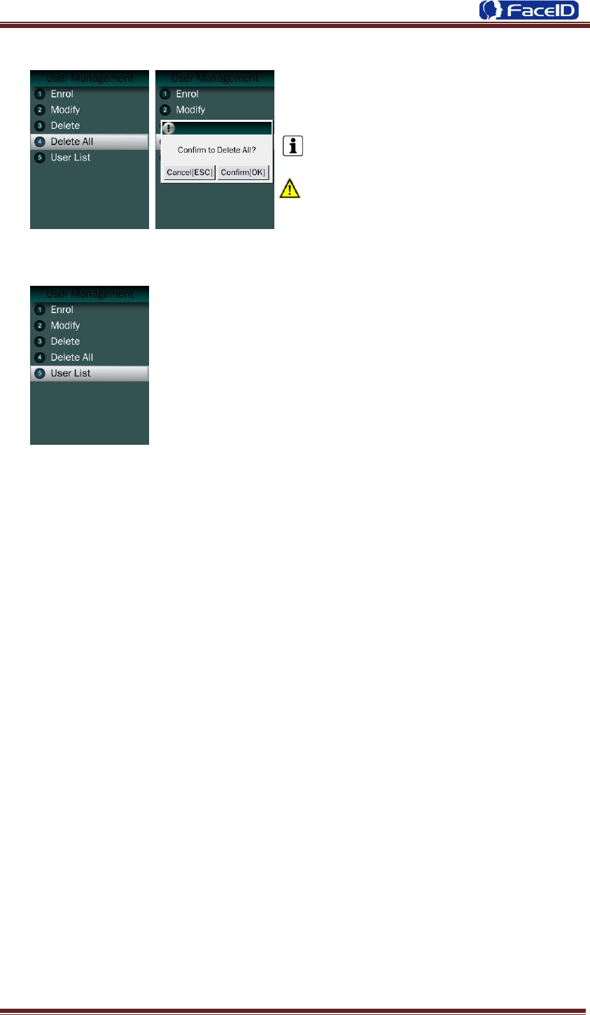
Delete All Users
Press [OK] (or [ESC]) to confirm (or
cancel) this process.
All user‟s ID, name and templates will be
erased.
This step is irreversible. Not affect Admin
data and records.
User List
Enter user list to check Un-enrolled and Enrolled list.
Press [OK] (or [ESC]) to confirm (or cancel) this process.
Confidential Page 16
3. 3 Data Management
Data Management Main Menu
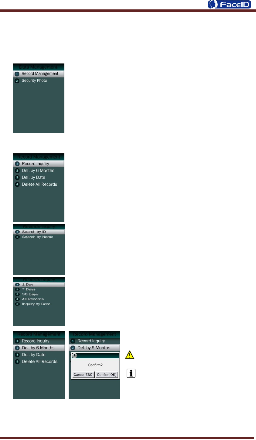
Record Management
Record Inquiry: User records can be inquiry by User
ID/Name.
Select a search mode to inquiry user records.
Select inquiry duration: 1 day/6 days /All records / from start
date to end.
Del. by 6 months
Before 6 months records will be erased.
This step is irreversible.
Backup all user data before doing this
step.
Confidential Page 17
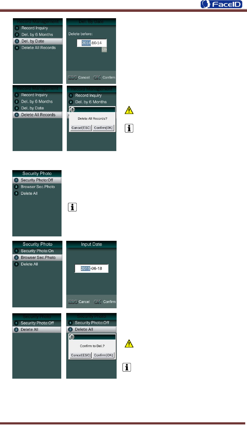
Del. by Date: Input the delete time.
Delete All Records
All records will be erased. This step is
irreversible.
Backup all user data before doing this
step.
Security Photo
Security Photo Switch: Turn on / off security photos function.
Default switch is off.
Security Photo Browser Switch: User
can input the date to browser the security
photo.
Delete All
All security photos will be erased.
This step is irreversible.
Backup all user data before doing
this step.
Confidential Page 18
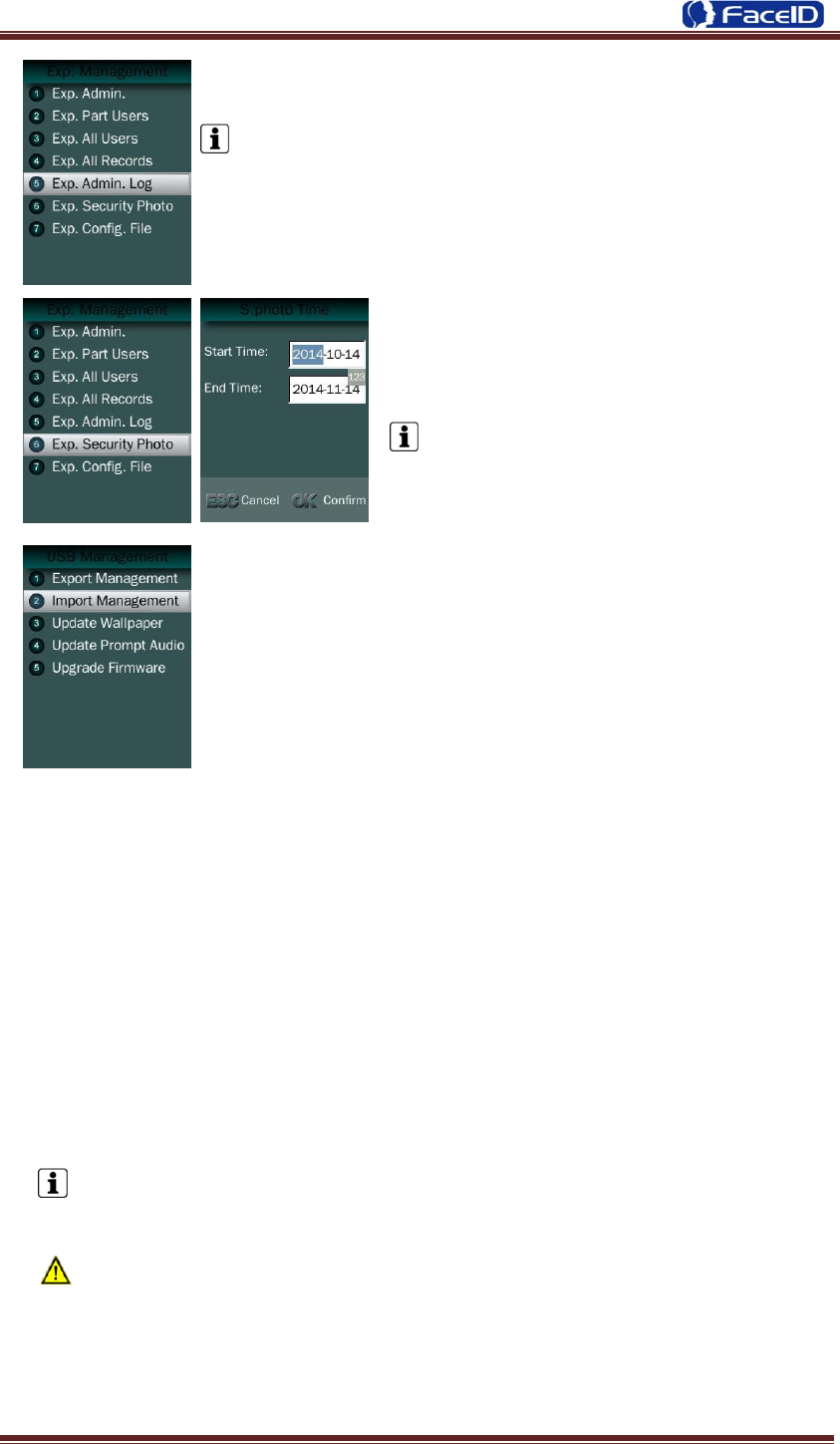
3.4 USB Management
USB Management Main Menu
Don‟t remove USB Disk while data transferring.
Try other USB Disk, if the terminal doesn‟t recognize it.
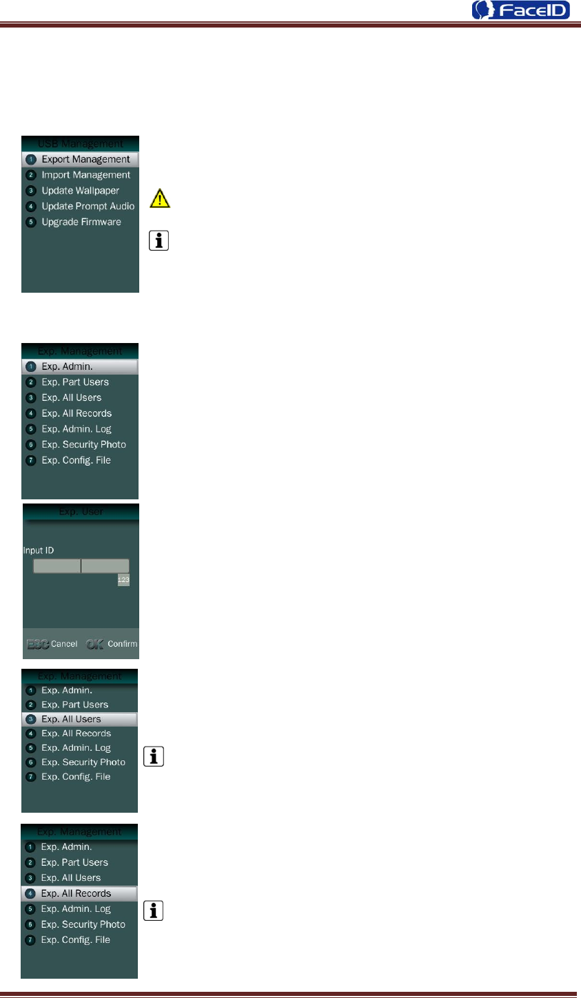
Export Management
Exp. Admin.: Export all admin. data into a file which named as
“MANAGER.TXT ”
Exp. Part Users: Export part user‟s data into a file which
named “USER.TXT”
Exp. All Users: Export data of all users.
Data is stored into a “USERALL.TXT” file.
Exp. All Records: Export all user records into a file, which
named as “TIME+SN”.TXT.
For example, TIME063.TXT, “063” is the last 3 bits of SN of
the terminal.
Confidential Page 19
Exp. Admin. Log: Export all admin operating logs.
Data is stored into a “LOG.TXT” file.
Exp. Security photos: Set a time duration of
exporting security photos
Security photos are saved in <security>
folder
Exp. Config. File: Export terminal configuration file into a file,
which named as “sys.dat”.
Import Management
Import admin
Import all administrators data from MANAGER.TXT file on an USB Disk into the
terminal.
Import Part Users
Import all users data from USER.TXT file on an USB Disk into the terminal.
Import All Users
Import all users data from USERALL.TXT file on an USB Disk into the terminal.
Import User List
Import all ID and name information of users from USERLIST.TXT file on an USB
Disk into the terminal.
It is a shortcut way to add user ID and name for a terminal before registration
process. The contents of USERLIST.TXT file are list of <ID>+<TAB Key> +
<Name>.
The range of user ID is from 1-99,999,999,999,999.
Import work code
Import all work code data from WORKCODE.TXT file on a USB Disk into the
terminal.
Confidential Page 20
The contents of WORKCODE.TXT file are list of <ID> + <TAB Key> + <Work
Code>.
The range of work code ID is from 1-99,999,999.
Import work status
Import all work status data from WORKSTATUS.TXT file on a USB Disk into the
terminal.
The contents of STATUS.TXT file are list of <ID> + <TAB Key> + <Work Status>.
The range of work status ID is from 1-255.
Import Config. File
Import terminal configuration file from sys.dat file on a USB Disk into the
terminal.
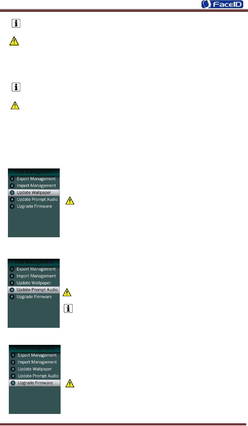
Set Wallpaper
Update the new wallpaper on a terminal.
240 * 320pix BMP/JPG file, and named to <idlepicture.bmp>
or <idlepicture.jpg>.
Set Prompt Audio
Update Successful and Failed prompt audio on a terminal.
PCM, 16000Hz, 16bit, stereo wave file, and named to
<granted.wav> and <deny.wav>
Keep audio length less than 1 second.
Firmware Upgrade
Upgrade a new firmware for a terminal.
Firmware files are <M2000.BIN> and <M2000.TXT>
Confidential Page 21
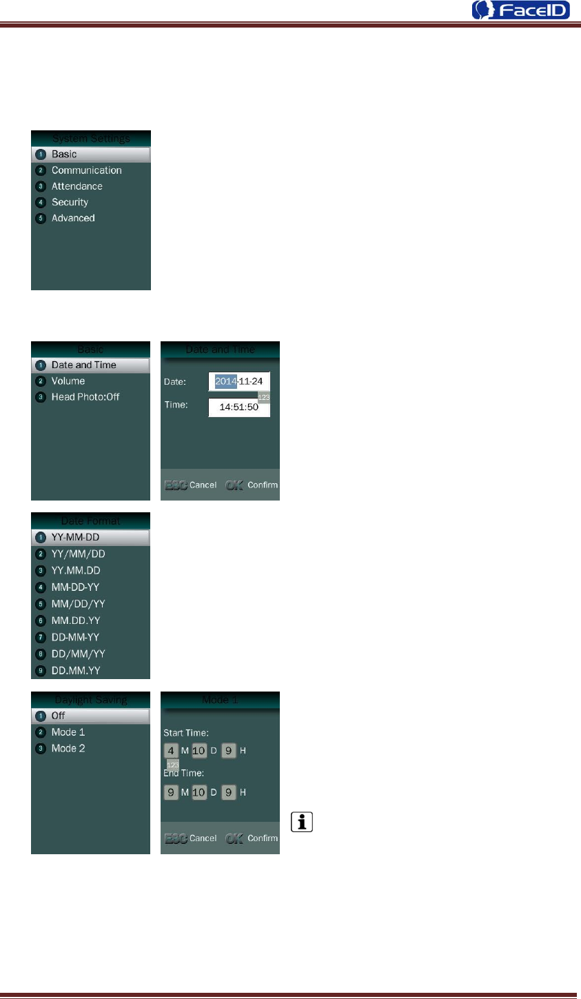
3.5 System Settings
System Main Menu
Basic
Date and Time
Date and Time: System date and time
can be set with this function.
Date Format: System date format can be set in 9 formats.
Daylight Saving: Set daylight saving time.
Select proper DST format according to DST
rule of your region. Month-Day-Hour: DST
time starts on 01:00 AM May. 1st, and ends
at 03:00 AM Oct. 2nd
Default is off.
Confidential Page 22
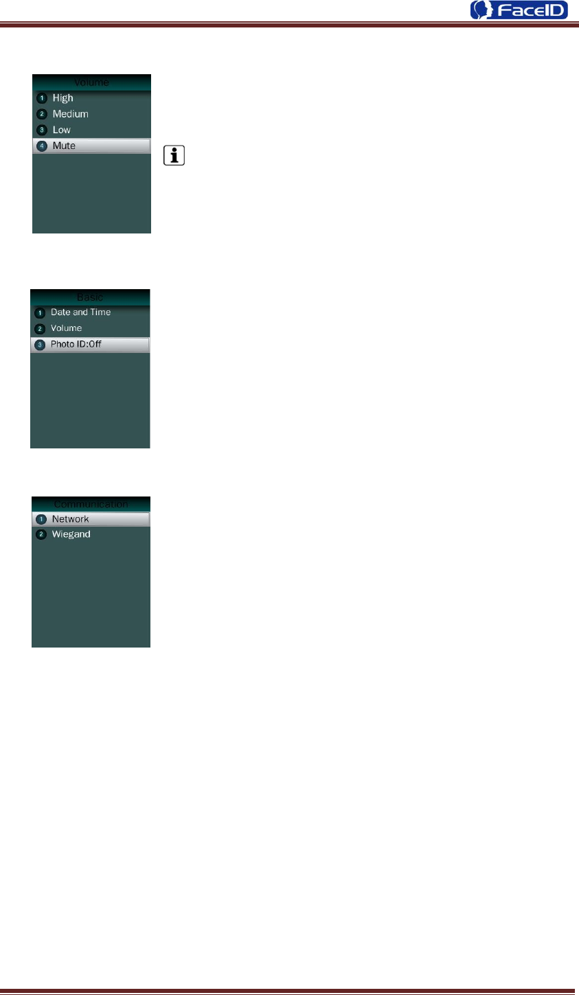
Volume
Set Volume: terminal support 4 modes to customers.
The default is medium.
Head Photo Switch
Photo ID Switch
Switch On: Users head photo will display on the screen
when the user verified successful.
Switch Off: Users head photo will not display on the screen
when user verified successful.
Communication
Communication: Network and Wiegand setting.
Confidential Page 23
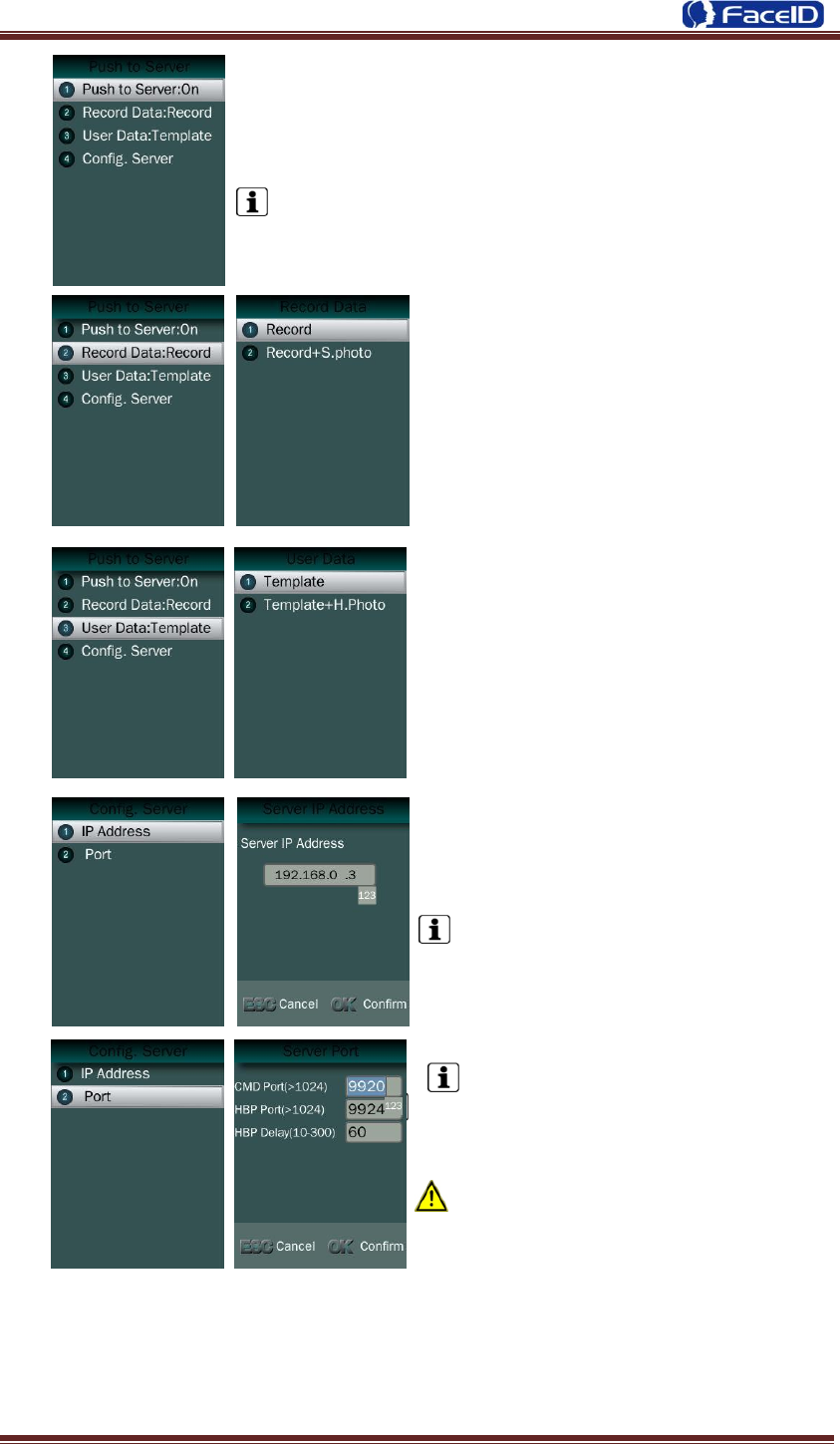
Network -Push to sever
1. Push to sever Switch: On/OFF
The default is off.
2. Record Data Switch: User can select
record data/record+security photo data be
pushed to the server.
3. User Data Switch: User can select user
template data/user template+head photo
data be pushed to the server.
4. Server configuration: User needs to set
IP address and port of server.
The default IP address is 192.168.0.3.
The default CMD/HBP port is
9920/9924.
The default HBP Delay is 60.
The port parameters have to more
than 1024. The HBP delay range is 10~300.
Confidential Page 24
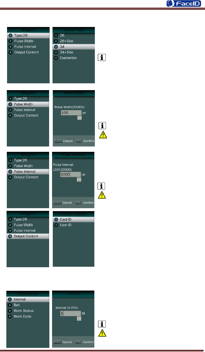
Communication -Wiegand Output
Wiegand Output-Type: System supports
standard Wiegand protocol output on the follow list.
The default type is Wiegand output 26.
Wiegand Output-Pulse Width
Set proper pulse width for wiegand output to
match the external wiegand input terminal.
The default Pulse Width is 100 us.
The pulse width range is 20~8000 us.
Wiegand Output-Pulse Interval
Set proper pulse interval for wiegand output to
match the external wiegand input terminal.
The default Pulse Interval is 1000 us.
The interval range is 200~20000us.
Wiegand Output-Content
The user can set Weigand output content with
Card ID or User ID.
Attendance
Attendance -Interval
Interval: Only the first record will be
saved while several records created by the
same user during defined interval time.
The default Interval is 1 minute.
The interval range is 0~255 minutes.
Confidential Page 25
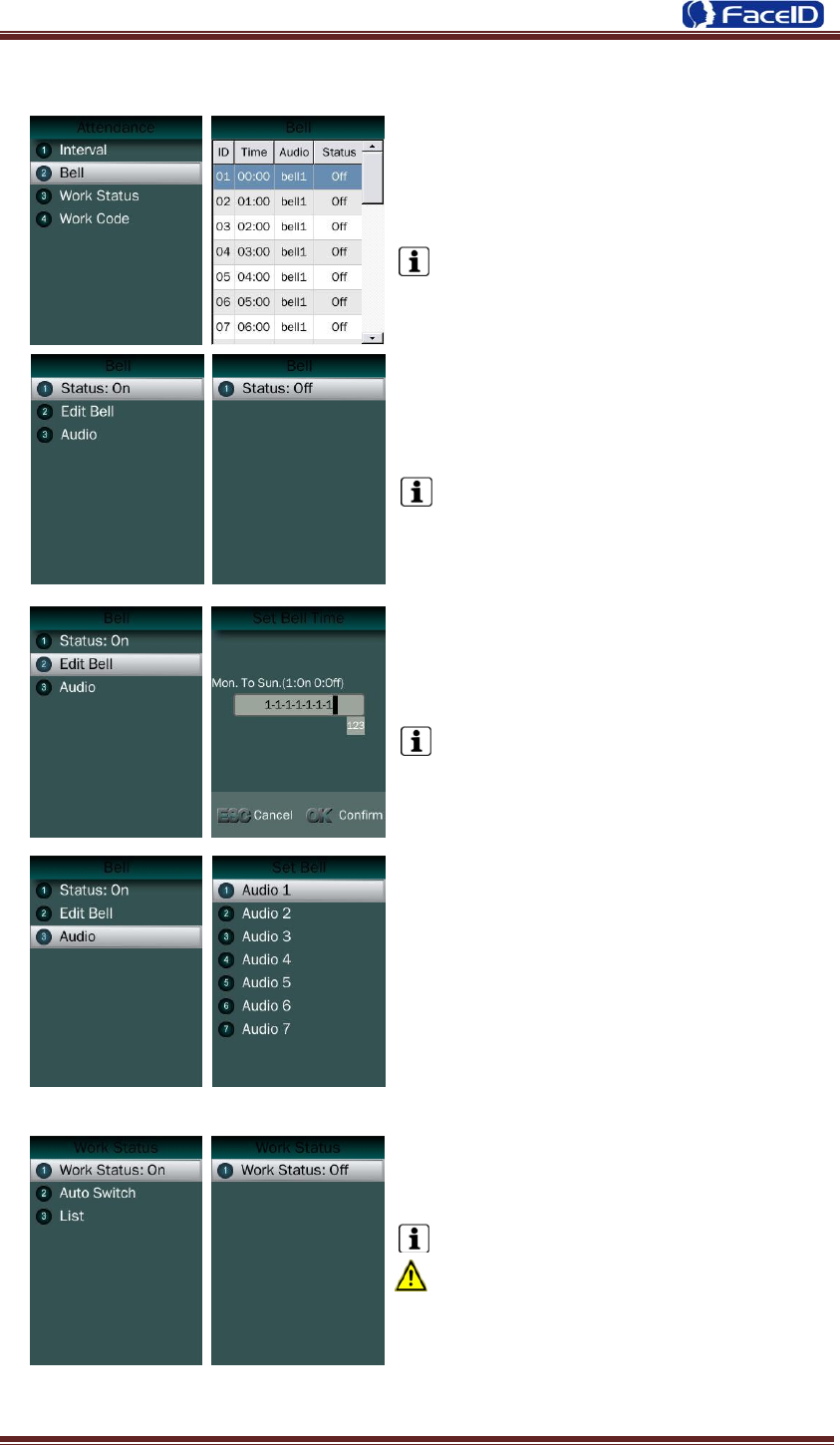
Attendance – Bell
Bell: User can select the attendance bell
on the list.
System supports 24 bell groups.
Bell Status Switch.
The default is off.
Edit Bell Time: User can set bell time
on/off from Monday to Sunday.
The default is 1-1-1-1-1-1-1, (1=On,
0=Off)
Bell Audio: System supports 7 groups
audio.
Attendance – Work Status
Work Status: It is defined to mark the
work status related to each record such as in,
out, overtime in, overtime out.
The default is off.
If Work Status is on, user could select the
desired work status by pressing down
key<↑/↓> or just finish the verification if desired
work status displaying on screen.
Confidential Page 26
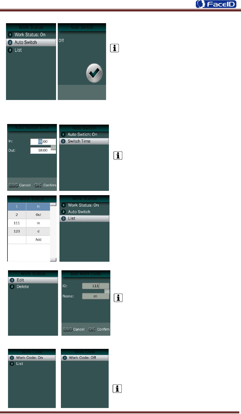
Auto Switch: It is defined to display the
work status automatically according to the time
that set.
For example, if the time of work status “in”
set as 9:00 and work status “out” set as 18:00,
the work status “in” will be displayed
automatically when time reach 9:00 till time
reach 18:00, the work status “out” will be
displayed automatically when time reach 18:00
till time reach 9:00 in next day. The default is
off.
Switch Time: User can set auto switch
time.
The default is 09:00 for “in” and 18:00 for
“out”.
List: User can edit or add the work status
on the list by selecting the desired one then
press ok to edit or delete.
Edit and Delete: User could edit the ID
and Name of work status.
The default work status is In/Out and they
can‟t be deleted. New added work status
could be deleted.
Attendance – Work Code
Work Code: It is defined to mark the work
code related to each record such as
engineering, maintaining, training etc.
The default is off. If Work Code is on, user
has to select the desired work code after
verification.
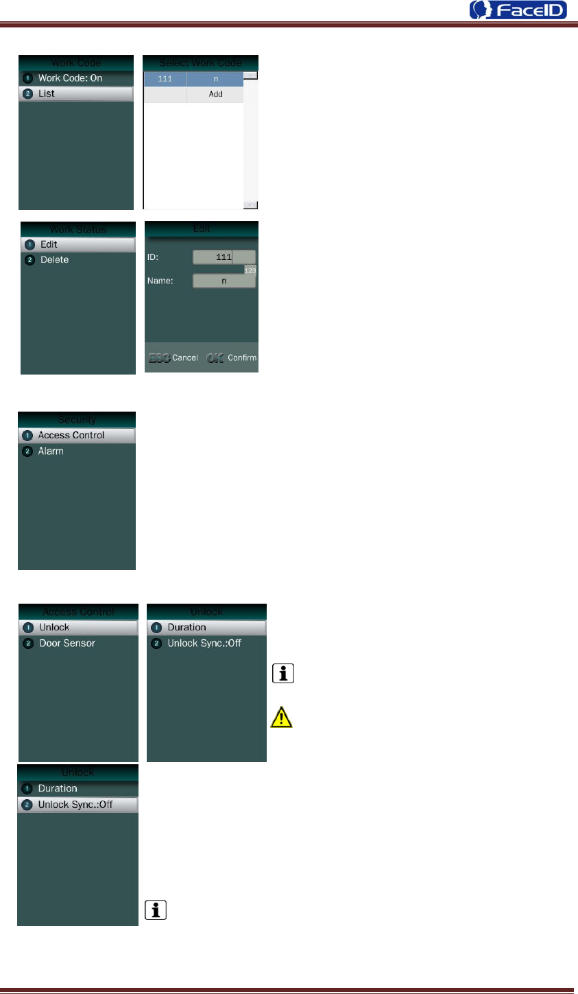
Confidential Page 27
Add: User can browse/add work code on
this list.
Edit and Delete: User edit the work status
and code with ID/Name.
Security
Security – Access Control
Unlock: User can set duration time of
unlock.
The default duration is 3 seconds.
The duration range is 0~10 seconds.
Unlock Sync: It is defined to enable the unlock execution
synchronic to the attendance interval. The unlock execution will be
only executed at the first time for the same user during defined
time of attendance interval time.
The default is off.
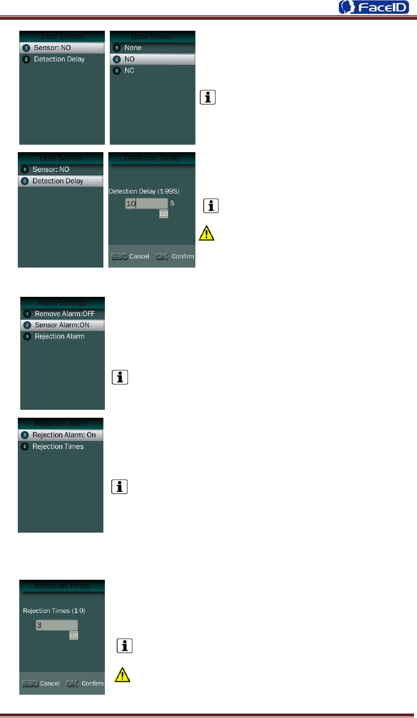
Confidential Page 28
Sensor: User can set sensor type with
None/NO/NC
The default sensor is “None”.
User can set detection delay time.
The default duration is 10 seconds.
The duration range is 1~99 seconds.
Security – Alarm
Sensor Alarm Switch: Enable/Disable sensor alarm
function.
The default is OFF.
Rejection Alarm Switch: Enable/Disable rejection alarm
function
The default is OFF.
Rejection Times: Set the rejection times to activate
rejection alarm
The default duration is 3 times.
The rejection time range is 1~9 times.
Confidential Page 29
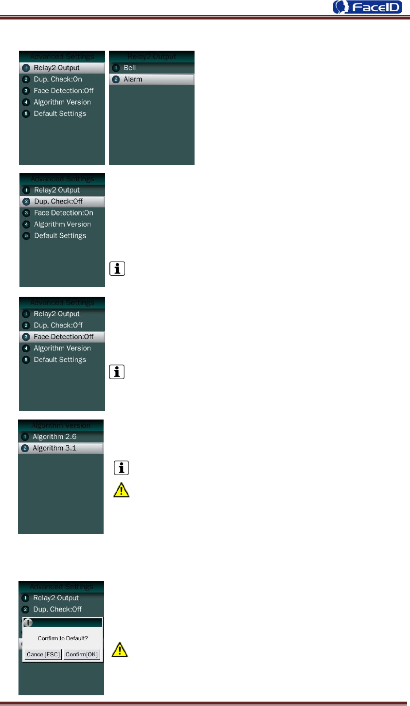
Advanced
Relay 2 Output: User can set output to
external Bell or Alarm output.
Duplication Check: System will match new enrolled user
with database to check this user already enrolled or not. If
system displaying “Similar to ID XX”, admin is suggested to
check this user for double enrollment.
The default is OFF.
Face Detection Switch: Enable/Disable face detecting
function when using Card and Photo recognition method.
The default detection is off.
Algorithm Version: User can select V2.6 or V3.1 algorithm for
a certain terminal.
The default version is V3.1.
The system will erase all enrolled users‟ templates if
change the algorithm version.
Default: This operation will delete all data and configurations.
And then initialize the device to factory setting.
If the administrator <confirm to default>, the terminal will
be in factory mode!
Confidential Page 30
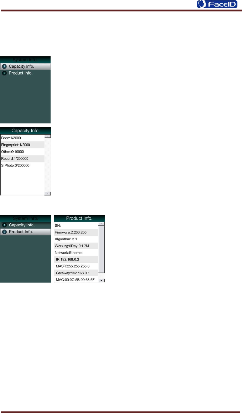
3.6 System Info.
Capacity Info.
Face: Current enrolled user numbers and total capacity of user
numbers for face related recognition mode.
Other: Current enrolled user numbers and total capacity of user
numbers for card and ID+PIN related recognition mode.
Record: Current record numbers and total capacity of record
numbers.
S. Photo: Current security photo numbers and total capacity of
security photos.
Unsent Records: Unsent record numbers while push to server
mode is on.
Unsent Users: Unsent user numbers while push to server mode
is on.
Product Info.
Product info: IP Address/Mask
Number/Gate/MAC/SN/Firmware
version/Algorithm.
Confidential Page 31
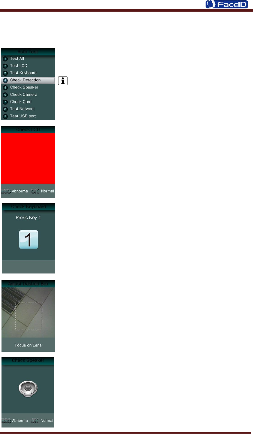
3. 7 Auto Test
Test All: Test all below hardware automatically
Press <OK> if it is working normal
Press <ESC> if it is working abnormal.
A list of status will be displayed after all testing.
Check LCD: Display Red, Green and Blue on the screen
Check Keyboard: Follow the screen message to check all keys.
Check Detection.
Check Speaker.

Confidential Page 32
Check Camera.
Check RFID Cards.
Check Network.
Check USB Port.
Confidential Page 33
3. Appendix
Appendix1. Product Specification
User capacity
2,000 users for face related verification method;
2,000 users for fingerprint related verification method
10,000 users for other verification methods including card, card and photo, ID
and Pin
Record capacity
Data Capacity:200,000
Security Photo: 200,000
Verification methods
Face
Face and Finger
Face or Finger
Finger
Card and Face
Card or Face
Card
Card and Photo
ID and Pin
Languages:
English
Spanish
Portuguese
Korean
Japanese
Turkish
Recognition algorithm
V2.6 or V3.1
Display: 3.5 inch TFT
Keypad: 4 * 4 touch keypad
RFID card: Proximity card or Mifare card (Optional)
Communication
TCP/IP
USB port
Power: 12V DC, 1.5A
Environment Light: 0-20000Lux
Working Temperature: 0°C -40°C
Working Humidity: 20% - 80%
Confidential Page 34
Appendix2. Caution
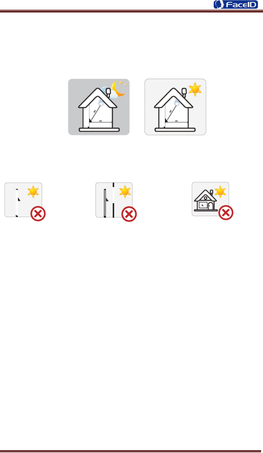
Installation Environment
Terminal should install inside of the room, and make sure the installation place far
with the window/door/light more than 2 meters.
Outside of the room Sunlight directly shines on the Sunlight slanted shines on the
terminal through the window. terminal through the window.
Restoration and restart
When the system halted and cannot quit, you can remove the adapter to restore and
restart the system, or you also can press <RESET> to restart the terminal.
Restore to default setting
Restore all parameters to the default setting.
Non-Water proof
The terminal is non-waterproof, please keep away from water.
Prevent from Falling
The parts in this terminal are friable; please prevent the terminal from dropping,
smashing, bending and high pressure.
Cleaning
Please use soft cloth or the other similar material to clean the screen and faceplate,
please avoid cleaning with water and cleanser.
Low Temperature Environment
The working temperature for screen and the main parts in this terminal are the normal
indoor temperature. The performance of this terminal will get worse, if the working
temperature extend this temperature range.

Confidential Page 35
Warning
Any Changes or modifications not expressly approved by the party responsible for
compliance could void the user‟s authority to operate the equipment.
This device complies with part 15 of the FCC Rules. Operation is subject to the following
two conditions: (1) This device may not cause harmful interference, and (2) this device
must accept any interference received, including interference that may cause undesired
operation.
Note: This equipment has been tested and found to comply with the limits for a Class B
digital device, pursuant to part 15 of the FCC Rules. These limits are designed to provide
reasonable protection against harmful interference in a residential installation. This
equipment generate, uses and can radiate radio frequency energy and, if not installed and
used in accordance with the instructions, may cause harmful interference to radio
communications. However, there is no guarantee that interference will not occur in a
particular installation. If this equipment does cause harmful interference to radio or
television reception, which can be determined by turning the equipment off and on, the
user is encouraged to try to correct the interference by one or more of the following
measures:
—Reorient or relocate the receiving antenna.
—Increase the separation between the equipment and receiver.
—Connect the equipment into an outlet on a circuit different from that to which the
receiver is connected.
—Consult the dealer or an experienced radio/TV technician for help.
This equipment complies with FCC radiation exposure limits set forth for an uncontrolled
Please use the equipped adapter
for the terminal, the other
unknown adapters will burn out
the terminal.
Please prevent the screen from oil
or any sharp objects.
environment.