Harbor Freight 1720 Lb Capacity 48 In X 96 Super Duty Trailer Product Manual
2015-05-27
: Harbor-Freight Harbor-Freight-1720-Lb-Capacity-48-In-X-96-In-Super-Duty-Trailer-Product-Manual-723676 harbor-freight-1720-lb-capacity-48-in-x-96-in-super-duty-trailer-product-manual-723676 harbor-freight pdf
Open the PDF directly: View PDF ![]() .
.
Page Count: 28

Page 2
For technical questions, please call 1-800-444-3353.
Item 69897
SAFETY OPERATION MAINTENANCEASSEMBLY
Table of Contents
Safety
.........................................................
2
Assembly
....................................................
6
Specifications
............................................
17
Operation
...................................................
17
Maintenance
..............................................
25
Parts List and Diagram
..............................
26
Reporting Safety Defects
...........................
28
Warranty
....................................................
28
WARNING SYMBOLS AND DEFINITIONS
This is the safety alert symbol. It is used to alert you to potential personal injury hazards.
Obey all safety messages that follow this symbol to avoid possible injury or death.
Indicates a hazardous situation which, if
not avoided,
will result in death or serious injury.
Indicates a hazardous situation which, if
not avoided,
could result in death or serious injury.
Indicates a hazardous situation which, if not avoided,
could result in minor or moderate
injury.
Addresses practices not related to personal injury.
VDC
Volts Direct Current
A
Amperes
WARNING marking concerning Risk
of Eye Injury. Wear
ANSI
-
approved
safety goggles with side shields.
Read the manual before
set-up and/or
use.
WARNING marking
concerning Risk of
Fire.
Connect trailer wiring to
properly fused circuit only.

Page 3
For technical questions, please call 1-800-444-3353.
Item 69897
SAFETYOPERATIONMAINTENANCE ASSEMBLY
IMPORTANT SAFETY INFORMATION
Read all safety warnings and instructions.
Failure to follow the warnings and instructions may result in serious
injury.
Save all warnings and instructions for future
reference.
The warnings, precautions, and instructions discussed in this instruction manual cannot cover all possible
conditions and situations that may occur. It must be understood by the operator that common sense and
caution are factors which cannot be built into this product, but
must be supplied by the
operator.
Assembly Safety
1.
Keep work area clean and dry.
Cluttered, damp, or wet work areas invite injuries.
2.
Keep children away from work area.
3.
Use eye protection. Wear ANSI-approved safety
impact eye goggles when assembling this Trailer.
4.
Do not modify this Trailer, and do not use this
Trailer for a purpose for which it was not intended.
Connection Safety
1.
Dress safely while connecting/disconnecting.
Do not wear loose clothing or jewelry, as they
can become caught in moving parts. Wear a
protective hair covering to prevent long hair from
becoming caught in moving parts. If wearing a
long-sleeve shirt, roll sleeves up above elbows.
Wearing safety work shoes is recommended.
2.
Do not setup or use this Trailer if under the influence
of alcohol or drugs. Read warning labels on
prescriptions to determine if your judgement or
reflexes are impaired while taking drugs. If there
is any doubt, do not attempt to use this Trailer.
3.
Stay alert. Watch what you are doing at all times.
Use common sense. Do not setup or use this Trailer
when you are tired or distracted from the job at hand.
4.
The tail light bulbs supplied with this Trailer are
for a 12 volt DC (negative ground) electrical
system
only. Do
not attempt to power the Light Bulbs
with any other type or voltage electrical current.
5.
Make sure the Hitch Coupler
(2) and the
vehicle’s ball hitch
(not included) are of equal
mating
size
(2") and are rated equal to or greater
than the weight of the Trailer and its payload.
6.
Before each use, attach the Trailer’s Safety
Chain
(1)
to the towing vehicle. Attach the Safety Chain to
the towing vehicle with equal length on each side.
Do
not allow the Safety Chain to drag on the ground.
Loading Safety
1.
Do not exceed the Trailer’s maximum payload
capacity of 1,720 lb. (evenly distributed).
2.
Properly and safely secure the payload in the Trailer.
Load the Trailer evenly from side to side with
60% of the load forward of the Axle
(11).
3.
Make sure the towing vehicle and its hitch are both
rated to safely tow the Trailer and its payload.
The towing capacity of the hitch is typically
stamped on the hitch drawbar.

Page 4
For technical questions, please call 1-800-444-3353.
Item 69897
SAFETY OPERATION MAINTENANCEASSEMBLY
Operation Safety
Note:
Selected recommendations in this section are adapted from
Selected recommendations in this section are adapted from
TOWING
A
TRAILER
-
Being
Equipped for Safety
, published by NHTSA. For full details, see that document.
1.
This Trailer is not a toy.
Do not allow children to play on or near this item.
2.
Take time to practice before driving on main roads.
3.
Never allow anyone to ride in or on the trailer.
4.
Do not transport animals in this trailer.
Before Each Use
1.
Check Tire
(13) condition and air pressure.
2.
Make sure wheel lug nuts/bolts
are properly tightened.
3.
Make sure hitch, coupler, draw bar, and other
equipment that connect the trailer and the tow
vehicle are properly secured and adjusted.
4.
Make sure wiring is properly connected — not
touching the
road, but
loose enough to make turns
without disconnecting or damaging the wires.
5.
Make sure all running lights, brake lights,
turn
signals, and hazard lights are working.
6.
Check that all items are securely
fastened on and in the trailer.
7.
Be sure the trailer jack, tongue support, and any
attached stabilizers are raised and locked in place.
8.
Check load distribution to make sure
the tow vehicle and trailer are properly
balanced front to back and side to side.
9.
Check side- and rear-view mirrors to
make sure you have good visibility.
10.
Check routes and restrictions on bridges and tunnels.
11.
Make sure you have wheel chocks and jack stands.
12.
Check trailer for loose bolts and nuts,
structural
cracks and bends, and any other
condition that may affect its safe operation.
Do
not
use
the
Trailer even if minor damage appears.
General Handling
1.
Use the driving gear that the towing vehicle
manufacturer recommends for towing.
2.
Drive at moderate speeds. This will place
less strain on your tow vehicle and trailer.
Trailer
instability
(sway) is more likely to
occur as speed increases.
Do not exceed
45
miles
per hour when towing the Trailer.
3.
Avoid sudden stops and starts that can
cause skidding, sliding, or jackknifing.
4.
Avoid sudden steering maneuvers that might
create sway or undue side force on the trailer.
5.
Slow down when traveling over bumpy
roads,
railroad crossings, and ditches.
6.
Make wider turns at curves and corners.
Because your trailer’s wheels are closer to the
inside of a turn than the wheels of your tow vehicle,
they are more likely to hit or ride up over curbs.
7.
To control swaying caused by air pressure changes
and wind buffeting when larger vehicles pass from
either direction, release the accelerator pedal to slow
down and keep a firm grip on the steering wheel.
Braking
1.
Allow considerably more distance for stopping.
2.
If you have an electric trailer brake controller and
excessive sway occurs, activate the trailer brake
controller by hand. Do not attempt to control
trailer sway by applying the tow vehicle brakes;
this will generally make the sway worse.
3.
Always anticipate the need to slow
down.
To reduce speed, shift to a lower gear
and press the brakes lightly.
Acceleration and Passing
1.
When passing a slower vehicle or changing
lanes,
signal well in advance and make sure you
allow extra distance to clear the vehicle
before you pull back into the lane.
2.
Pass on level terrain with plenty of clearance.
Avoid passing on steep upgrades or downgrades.
3.
If necessary, downshift for improved
acceleration or speed maintenance.
4.
When passing on narrow roads, be careful not
to go onto a soft shoulder. This could cause
your trailer to jackknife or go out of control.

Page 5
For technical questions, please call 1-800-444-3353.
Item 69897
SAFETYOPERATIONMAINTENANCE ASSEMBLY
Downgrades and Upgrades
1.
Downshift to assist with braking on downgrades
and to add power for climbing hills.
2.
On long downgrades, apply brakes at intervals to
keep speed in check. Never leave brakes on for
extended periods of time or they may overheat.
3.
Some tow vehicles have specifically calibrated
transmission tow-modes. Be
sure to use the
tow
-
mode recommended by the manufacturer.
Backing Up
1.
Put your hand at the bottom of the steering wheel.
To
turn left, move your hand left.
To turn right,
move
your hand right.
2.
Back
up
slowly.
3.
Because mirrors cannot provide all of the
visibility you may need when
backing
up,
have someone outside at the rear of the
trailer to guide you whenever possible.
4.
Use slight movements of the steering wheel
to adjust direction. Exaggerated movements
will cause greater movement of the trailer.
5.
If
you have difficulty, pull forward and realign
the tow vehicle and trailer and start again.
Parking
1.
Try to avoid parking on grades.
2.
If possible, have
someone outside
to guide you as you park.
3.
Once
stopped, but before shifting into Park:
a.
Have
someone place blocks on the
downhill side of the trailer wheels.
b.
Apply the parking brake.
c.
Shift
into
Park.
(first or reverse gear for manual transmissions)
d.
Then
remove your foot from the brake pedal.
Following this parking sequence is important to
make sure your vehicle does not become locked in
Park because of extra load on the transmission.
4.
Before uncoupling a trailer:
a.
Place blocks at the front and rear of the
trailer tires to ensure that the trailer does not
roll away when the coupling is released.
b.
An unbalanced load may cause the
tongue to suddenly rotate upward;
therefore,
before
uncoupling, place jack stands
under the rear of the trailer to prevent injury.
TRAILER LICENSING NOTICE
Some
states
may
consider this Trailer a vehicle requiring registration, licensing, and titling.
Check with your State Department of Motor
Vehicles for information and
guidance on registering, licensing, and titling the Trailer.
Maintenance Safety
1.
Maintain labels and nameplates on
the
trailer.
These
carry important
information.
If
unreadable
or
missing,
contact
Harbor
Freight
Tools for a replacement.
2.
Replacement parts and accessories: when servicing,
use only identical replacement parts.
Only use accessories intended for use
with this Trailer. Approved accessories are
available from Harbor Freight Tools.
3.
Maintain this Trailer with care. Keep this Trailer
clean and dry for better and safer performance.
4.
For your safety, service and maintenance should
be performed regularly by a qualified technician.
5.
When not in use, store Trailer in a
dry
location to inhibit rust. Lock up Trailer,
and keep out of reach of children.
SAVE THESE INSTRUCTIONS.
Page 6
For technical questions, please call 1-800-444-3353.
Item 69897
SAFETY OPERATION MAINTENANCEASSEMBLY
Assembly Instructions
Read the
ENTIRE
IMPORTANT SAFETY INFORMATION
section at the beginning of this
manual including all text under subheadings therein before set up or use of this Trailer.
Note:
For additional information regarding the parts listed in the following
For additional information regarding the parts listed in the following
pages,
refer to
Parts List and Diagram
on page
26.
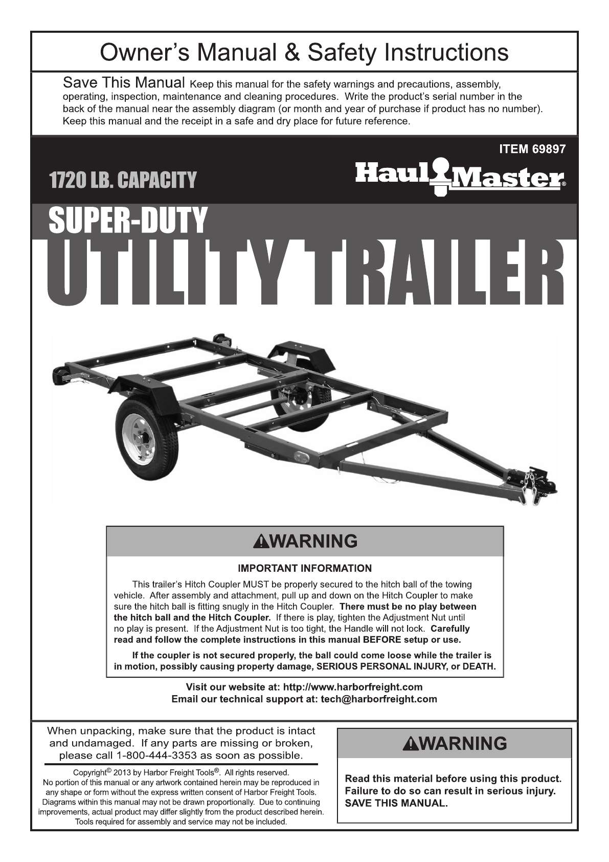
1.
Lay out the Front Left Side Rail (15), Front Right
Side Rail (27), Front Member (28) and two Cross
Members
(21). Assemble these parts using eight
M10
x
20 Bolts (31) and M10 Nuts (33).
(See Figure
A.)
FRONT OF TRAILER
Front Left Side Rail (15)
Front Right Side Rail (27)
(31,33)
(31,33)
(31,33)
(31,33)
(31,33)
(31,33)
(31,33)
(31,33)
Front Member (28)
Cross
Member (21)
Cross
Member (21)
TO CENTER OF TRAILER
Figure
A:
Front Bed Rail Assembly
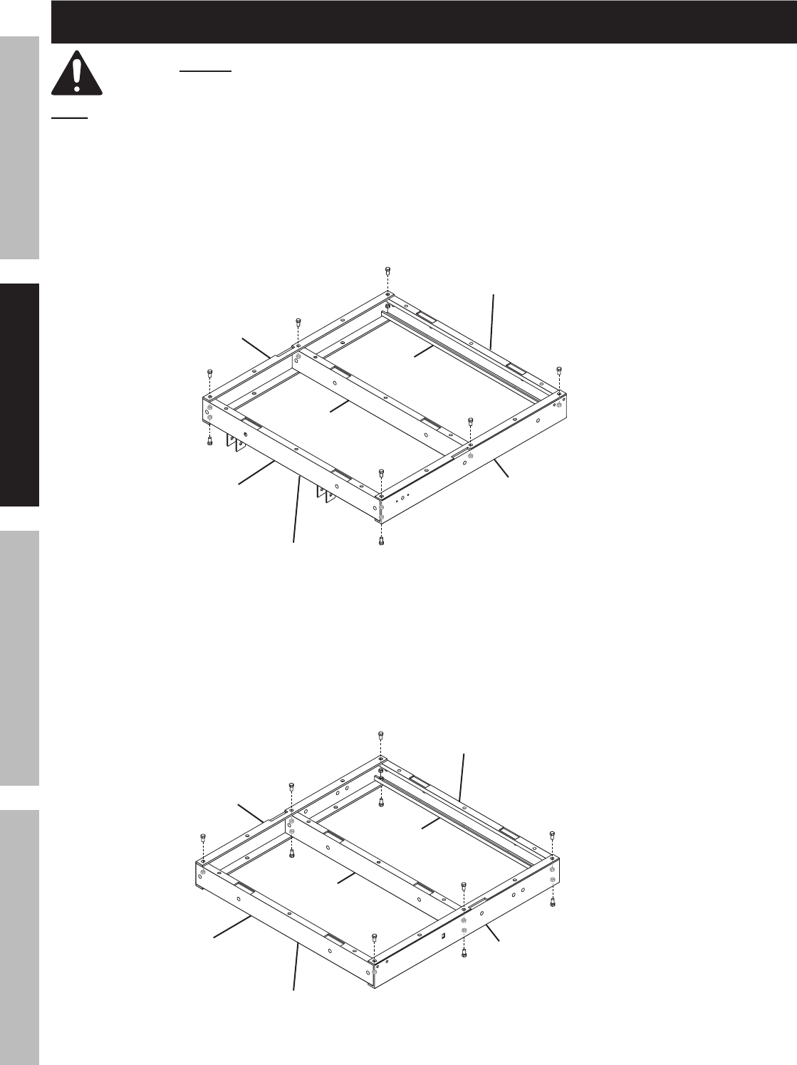
2.
Lay out the Rear Left Side Rail (20), Rear Right Side
Rail (22), and three Cross Members (21).
Assemble these parts using ten M10
x
20 Bolts (31)
and M10 Nuts (33).
(See Figure
B.)
Rear Left Side Rail (20)
(31,33)
(31,33)
(31,33)
(31,33)
(31,33)
(31,33)
(31,33)
(31,33)
(31,33)
(31,33)
Rear Right Side Rail (22)
Cross Member (21)
REAR OF TRAILER
Cross
Member (21)
Cross
Member (21)
TO CENTER OF TRAILER
Figure
B:
Rear Bed Rail Assembly
Page 7
For technical questions, please call 1-800-444-3353.
Item 69897
SAFETYOPERATIONMAINTENANCE ASSEMBLY
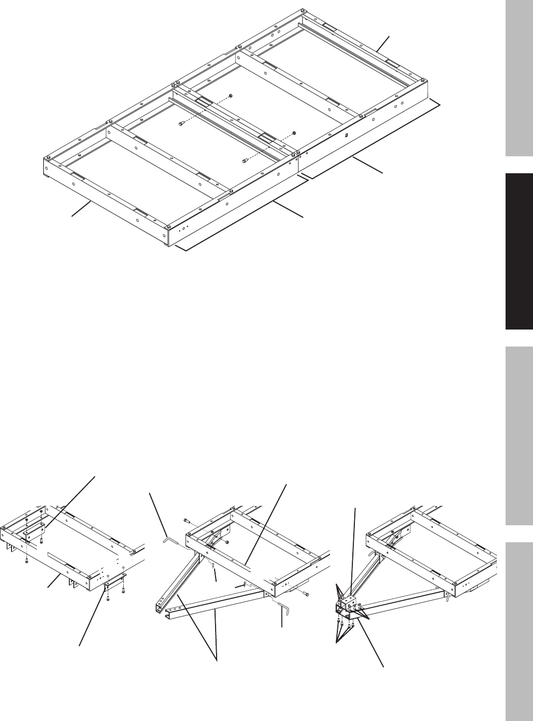
3.
Attach the Front and Rear Bed Rail Assemblies using
two M10
x
20 Bolts (31) and M10 Nuts (33).
(See Figure
C.)
(31)
(31)
(33)
(33)
REAR OF TRAILER
FRONT OF TRAILER
Front Bed
Rail Assembly
Rear Bed
Rail Assembly
Figure
C:
Attaching Front and Rear Bed Rail Assemblies
4.
Attach Drawbar Brackets (6) to the Front Left and
Front Right Side Rails (15, 27) using two M10
x
20
Bolts (31) / M10 Nuts (33) and two M10
x
30
Bolts (7) / M10 Nuts (33).
(See Figure D.)
5.
Attach the Left and Right Drawbar Rails (5) to the
Front Member (28) using two L-Latches (30) and
3mm R-Clips (34). Then attach the Left and Right
Drawbar Rails to the Drawbar Brackets using two
M12
x
25 Bolts (29) and M12 Nuts (35).
(See Figure D.)
L-Latch (30)
Left and Right
Drawbar Rails (2pc) (5)
(15)
(27)
(31,33)
(31,33)
(31)
(31)
(7)
(31,33)
FRONT OF
TRAILER
Drawbar Bracket (6)
Drawbar Bracket (6)
Coupler Base (3)
Front Member (28)
Drawbar T-Plate (4)
L-Latch (30)
(29)
R-Clip (34)
(33)
(33)
(33)
(33)
(33)
(33)
(33)
(33)
(33)
(33)
(33)
(33)
(33)
(33)
(33)
(33)
(33)
(33)
(33)
(33)
(33)
(33)
(33)
(33)
(33)
(33)
(33)
(33)
(33)
(33)
(33)
(33)
(33)
(33)
(33)
(33)
(33)
(33)
(33)
(33)
(33)
(33)
(33)
(33)(33)
(33)
(29)
(7)
(7)
(7)
(7)
(7)
(7)
(35)
(35)
(35)
Front Member (28)
(31,33)
6.
Attach the Coupler Base (3) to the Left and Right
Drawbar Rails using six M10
x
20 Bolts (31) and M10
Nuts (33). Then attach the Drawbar T-Plate (4) under
the Left and Right Drawbar Rails, using four M10
x
20
Bolts (31) and M10 Nuts
(33).
(See Figure D.)
Figure
D:
Drawbar Assembly
Page 8
For technical questions, please call 1-800-444-3353.
Item 69897
SAFETY OPERATION MAINTENANCEASSEMBLY
7.
With assistance, turn the frame upside down.
8.
Attach the Right Spring Hanger (26) to the
Front Right Side Rail (27) using two M10
x
20
Bolts
(31) and M10 Nuts (33).
(See Figure E.)
9.
Attach the Left Spring Hanger (17) to the Front Left
Side Rail (15) using two M10
x
20 Bolts (31) and M10
Nuts (33).
Right Spring Hanger (26)
Rear Right Side Rail (22)
Front Right Side Rail (27)
(25,33)
(25,33)
(31,33)
(7,33)
(31,33)
10.
Attach the Right Spring Hanger (26) to the
Rear Right Side Rail (22) using one M10
x
30
bolt (7), two M10
x
25 Carriage Bolts (25) and
three M10 Nuts (33).
(See Figure E.)
11.
Attach the Left Spring Hanger (17) to the Rear
Left Side Rail (20) using one M10
x
30 Bolt (7),
two
M10
x
25 Carriage Bolts (25) and three
M10 Nuts (33).
Figure
E:
Attaching Spring Hanger (Right Side View)
12.
Attach a Fender Bracket (9) to the Right
Spring Hanger (26) using two M10
x
20 Bolts
(31) and M10 Nuts (33).
(See Figure F.)
13.
Attach a Fender Bracket (9) to the Left
Spring Hanger
(17) using two M10
x
20
Bolts (31) and M10 Nuts (33).
14.
Attach a Fender (18) to the Right Fender
Bracket using M10
x
20 Bolts (31) and
M10 Nuts (33).
(See Figure F.)
15.
Attach a Fender (18) to the Left Fender Bracket
using M10
x
20 Bolts (31) and M10 Nuts (33).
16.
On each side, place a Spring (8) on Spring Hangers
(17, 26) with the spring eyes forward. Insert two
M12
x
75 Bolts (16) through the Springs, and secure
the Bolts with M12 Nuts (35).
(See Figure F.)
17.
Place the Axle (11) on top of the Springs (8). Align
depressions on Axle with protrusions on Springs.
Place Spring Plates (10) under Springs, and insert
U-Bolts (32) through the Axle, Springs and Spring
Plates. Secure the Axle with M10 Nuts (33) screwed
onto the U-Bolts.
(See Figure F.)
Figure
F:
Fender Assembly
Right Spring
Hanger (26)
U-Bolt (32)
(31,33)
(31,33)
(16,35)
(16)
(35)
Fender Bracket (9)
Spring (8)
Spring Plate (10)
Axle (11)
Fender (18)
U-Bolt (32)
Axle (11)
(33x4)
(33x4)
(33x4)
(33x4)
(33x4)
(33x4)
Page 9
For technical questions, please call 1-800-444-3353.
Item 69897
SAFETYOPERATIONMAINTENANCE ASSEMBLY
18.
BEARING
PACKING
INSTRUCTIONS
WARNING!
Whenever a hub is disassembled (if
a
hub
on
a new unit requires assembly or a hub is
disassembled for maintenance), the
following procedure
MUST
be obeyed.
Failure to read and obey all of the following instructions completely will void the warranty
and can result in damage to the Trailer, property damage, or serious injury.
a.
Using a suitable solvent, thoroughly clean the
bearings and the rest of the parts in the Hub
Assembly of all grease, dirt, metal shavings, or
any other foreign object.
The parts must be
cleaned even if they are new or
appear
clean.
appear clean.appear
b.
Allow all pieces to dry completely.
c.
Make sure that your hands are thoroughly
clean and the bearing
packer
(not
included)
is also thoroughly clean.
d.
Place fresh, clean bearing grease in the packer.
e.
With the grease-filled bearing packer in one hand
and the bearing in the other, press the bearing
into the grease, forcing the grease inside the slots
in the bearing. Continue doing this until every
slot in the bearing is completely full of grease.
f.
Finish assembling the hub/wheel assembly,
being careful not to get any dirt or
debris on any part of the assembly.
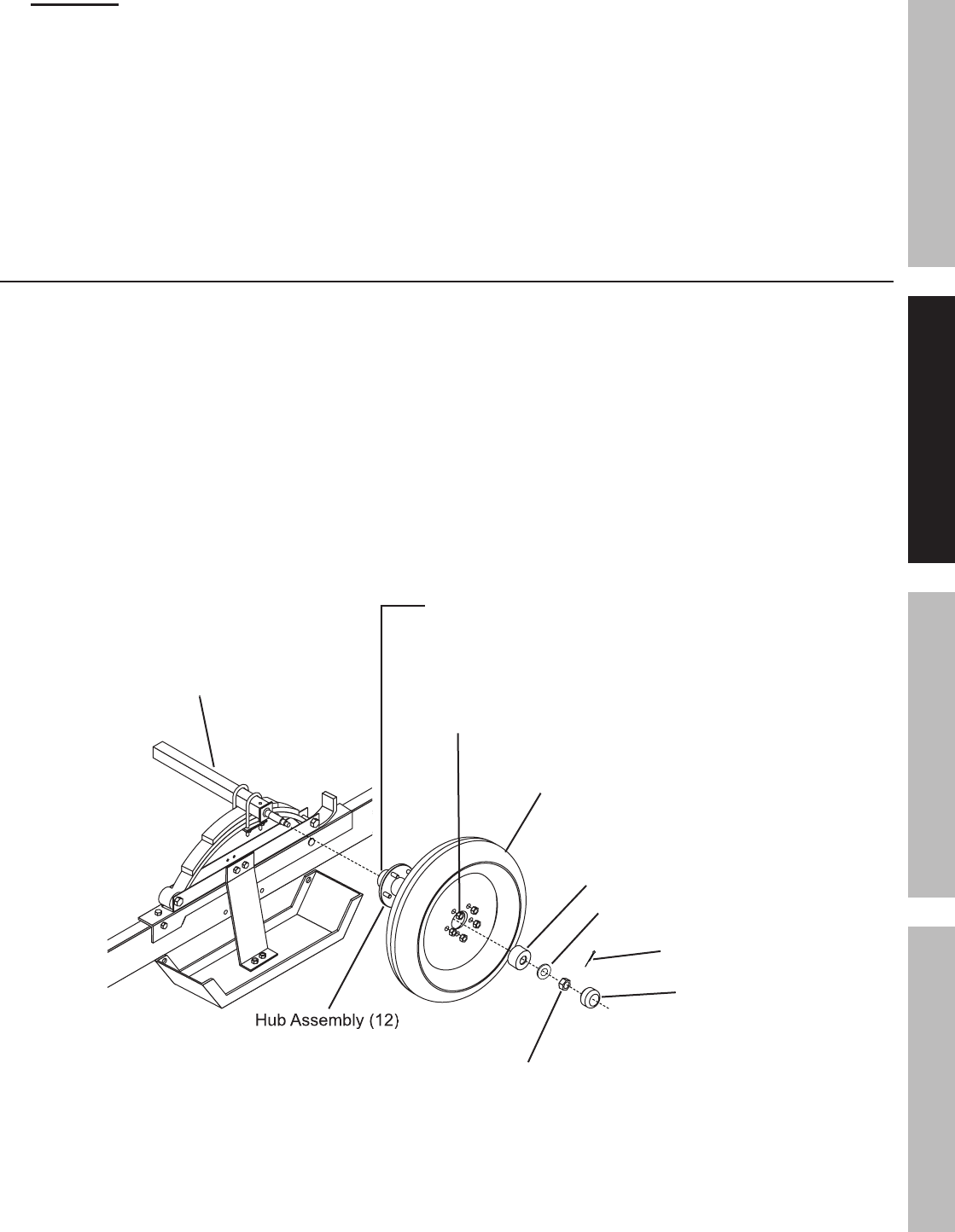
19.
Carefully slide the Hubs (12) over the spindles
at each end of the Axle (11).
(See Figure G.)
20.
Insert the Bearings (39) and Flat Washers (19) on the
spindles. Screw an M22 Castle Nut (37) tightly onto
each spindle. Then back the Castle Nut off slightly so
that the Hubs can just move freely.
(See Figure G.)
21.
Insert a Cotter Pin (38) through the Castle
Nut and hole at the end of each spindle, and
spread the Cotter Pins.
(See Figure G.)
22.
Fill the Dust Cap (14) with bearing grease.
Then press each Dust Cap onto the Hub
Assembly (12).
(See Figure G.)
23.
Grease each grease fitting located on the
backside of each Hub Assembly.
24.
Install a Tire (13) on each Hub Assembly, then secure
the Tires, using M12 Lug Nuts (40).
Torque the Lug
Nuts to 85
–
90 ft. lb. (See Figure G.)
Cotter Pin (38)
Hub Assembly (12)
Bearing (39)
Tire (13)
Lug Nuts (40)
Axle (11)
Castle Nut (37)
Dust Cap (14)
NOTE: PERIODICALLY,
GREASE SEAL ON
BACKSIDE OF HUB (12).
Axle (11)
Flat Washer (19)
Figure
G:
Hub/Wheel Assembly
Page 10
For technical questions, please call 1-800-444-3353.
Item 69897
SAFETY OPERATION MAINTENANCEASSEMBLY
25.
With assistance, turn the Trailer
assembly right side up.
26.
Attach the Coupler (2) to the Coupler Base
(3),
using two M12
x
75 Bolts (16) and M12 Nuts (35).
Thread one of the M12
x
75 Bolts (16) through the
center link of the Safety Chain (1).
(See Figure H.)
27.
Lock the Coupler Trigger, using Locking Pin
(47)
and 2mm R-Clip (43).
(See Figure H.)
28.
Attach the Light Brackets (24) to the Rear Left Side
Rail (20) and Rear Right Side Rail (22) using M10
x
20
Bolts (31) and M10 Nuts (33).
(See Figure H.)
29.
Attach the License Plate Bracket (44) with the
Left Tail Light (23L) to the Light Bracket
(24)
on the Rear Left Side Rail (20), using
M10
x
20 Bolts (31) and M10 Nuts (33).
30.
Attach the Right Tail Light (23R) to the
Light Bracket
(24) on the Rear Right Side
Rail (22), using M10
x
20 Bolts (31) and
M10 Nuts (33).
(See Figure H.)
31.
Open the lenses of the Side Running Lights (45).
Run the wire lead of a Side Running Light through
the center hole located at the front end of the
Front Left Side Rail (15). Then attach the Side
Running Light to the Front Left Side Rail, using
4mm Self-Tapping Screws (46).
(See Figure H.)
32.
Run the wire lead of the remaining Side Running
Light (45) through the center hole located at
the front end of the Front Right Side Rail (27).
Then
attach
the Side Running Light to the Front Right
Side Rail, using 4mm Self-Tapping Screws (46).
33.
Reinstall the lenses on the two
Side
Running
Lights
(45).
(See Figure H.)
(31,33)
Safety Chain (1)
Coupler (2)
Coupler
Base (3)
(16,35)
(16,35)
(16,35)
(16,35)
(16,35)
(16,35)
(16,35)
Side Running
Light (45)
Right Tail Light (23R)
(31,33)
(31,33)
(31,33)
(31,33)
(31,33)
(31,33)
Left Tail
Light (23L)
Light
Bracket (24)
Light Bracket (24)
License Plate Bracket (44)
Rear Left Side Rail (20)
Front Left Side Rail (15)
Rear Right Side Rail (22)
Front Right Side Rail (27)
Side Running
Light (45)
(47)
(43)
Right Tail Light (23R)
Light (23L)
Tapping Screws
x4 (46)
Coupler
Trigger
Figure
H:
Coupling Attachment / Light Installation

Page 11
For technical questions, please call 1-800-444-3353.
Item 69897
SAFETYOPERATIONMAINTENANCE ASSEMBLY
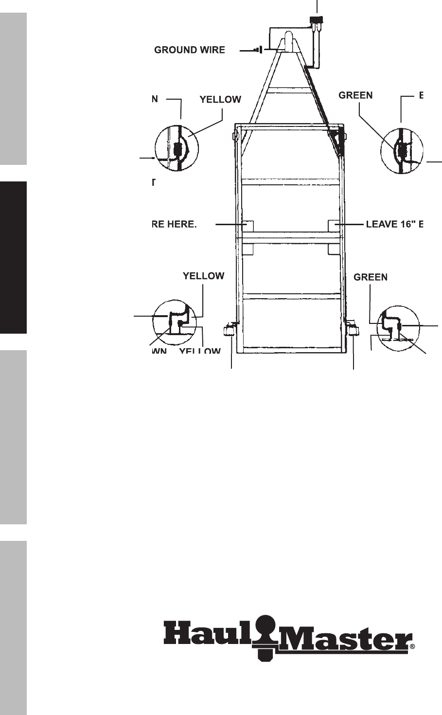
NOTE:
Only a qualified technician should perform
the electrical service that may be needed to
enable your particular make/model vehicle to
power the Trailer’s 12 volt DC lighting system.
This is beyond the scope of this manual.
34.
Have a qualified service technician install a 4-wire,
12VDC connector in the trunk area of your vehicle.
35.
Locate the vehicle’s connector plug near the
Trailer’s Coupler (2) and lay out the Trailer’s
wiring harness wires.
(See Figure I.)
36.
Connect the brown wire to the vehicle’s Left
Tail Light by stripping, wrapping, and taping
the connector plug.
(See Figure I.)
37.
Connect the yellow wire to the vehicle’s left
signal and stop light wire.
(See Figure I.)
38.
Connect the green wire to the vehicle’s right
signal and stop light wire.
(See Figure I.)
Note
: Some foreign vehicles may require
: Some foreign vehicles may require
and adapter to convert their 5-wire system
to a 4-wire vehicle connector plug.
39.
Attach the white ground wire at the plug
end of the wiring harness to the small hole
on the Coupler Base (3) with a 1/4" tapping
screw (not included).
(See Figure I.)
40.
Leave about 18" of wire beyond the Coupler
(2),
and run the wiring harness along the inside of
the Right Drawbar Rail
(5) to the Front
Right
Side Rail
(27). Then, split the yellow/brown
wires from the green/brown wires.
41.
Run the yellow/brown wires along the
inside of the Front Cross Member
(21) to
the Side Running Light
(45) located on the
Front
Left
Side
Rail
(15). Then, run the green/
brown wires along the inside of the Front Right
Side Rail
(27) to the other Side Running Light.
42.
Connect the wire lead from the two Side Running
Lights to the brown wire on each side of the
trailer, using wire connectors. Then, insert wire
clips along the entire length of the side rails of
the Trailer to hold down the wiring harness.
43.
Run the yellow/brown wires to
the
Left
Tail
Light
(23L). Strip approximately
3/4" of insulation off the ends of the wires.
Connect
the yellow
wire to the yellow wire of
the
Left
Tail
Light. Then, connect the brown
wire to the brown wire of the Left Tail Light.
44.
Run the green/brown wires to
the
Right
Tail
Light
(23R). Strip approximately
3/4" of insulation off the ends of the wires.
Connect
the green wire to the green wire of
the Right Tail Light. Then, connect the brown
wire to the brown wire of the Right Tail Light.
Page 12
For technical questions, please call 1-800-444-3353.
Item 69897
SAFETY OPERATION MAINTENANCEASSEMBLY
WIRE LEAD
FROM
SIDE RUNNING LIGHT
SIDE RUNNING LIGHT
(45)
WHITE GROUND WIRE
WHITE GROUND WIRE
WIRE LEAD
FROM
SIDE RUNNING LIGHT
(45)
BROWN
BROWN
YELLOW
GREEN
BROWN
BROWN
YELLOW
YELLOW
YELLOW
BROWN
BROWN
BROWN
GREEN
GREEN
BROWN
BROWN
LEAVE 16" EXCESS WIRE HERE.
LEAVE 16" EXCESS WIRE HERE.
LEAVE 16" EXCESS WIRE HERE.
LEAVE 16" EXCESS WIRE HERE.
LEFT TAIL LIGHT (23L)
RIGHT TAIL LIGHT (23R)
WIRE HARNESS CONNECTOR PLUG
Figure
I:
Trailer Wiring
Page 13
For technical questions, please call 1-800-444-3353.
Item 69897
SAFETYOPERATIONMAINTENANCE ASSEMBLY
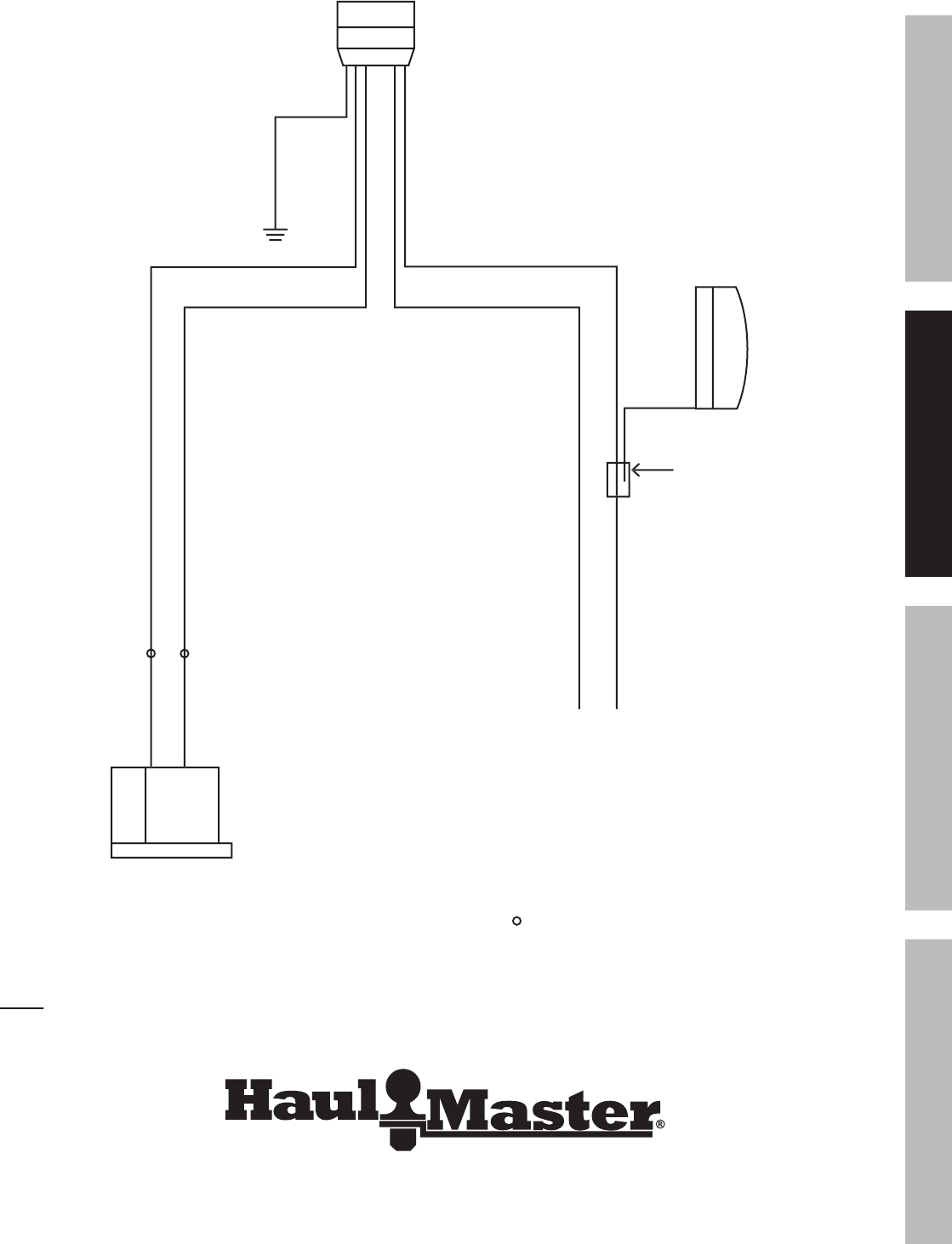
White ground wire
to trailer tongue
4-pin connector
Brown
Brown
Brown tail light wire
Black
side marker lights
wire clip
Right light (Green lead)
Wired same as left side
KEY / COLOR CODES
Brown:
Tail and side marker lights
Green:
Right directional and stop light
Yellow:
Left directional and stop light
White:
Ground to trailer frame
Indicates wire nut connection
Left light (Yellow lead)
Yellow
Yellow
Green
Brown
Figure
J:
Wiring Diagram
Note:
Some trailer tail lights will have two leads instead of three.
Some trailer tail lights will have two leads instead of three.
They connect to the harness leads the same way; brown to brown, color to color.
Page 14
For technical questions, please call 1-800-444-3353.
Item 69897
SAFETY OPERATION MAINTENANCEASSEMBLY
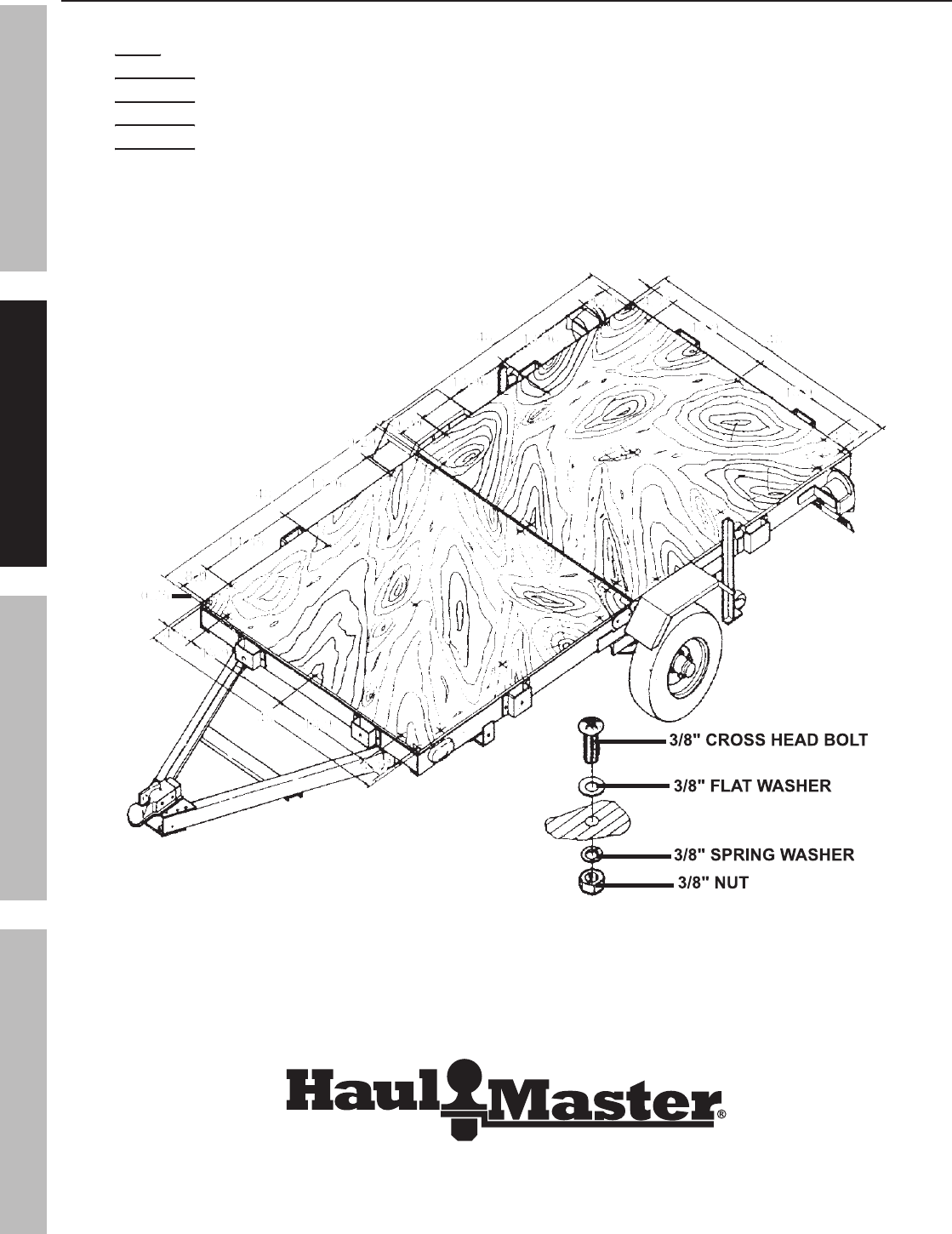
Optional Bed Installation (not included)
Minimum Required Parts:
a.
Qty. 2
Qty. 2
:
3/4" x 48" x 48" Plywood (not included).
b.
Qty. 24-30
Qty. 24-30
:
3/8" Cross Head Bolts (not included).
c.
Qty. 24-30
Qty. 24-30
:
3/8" Flat Washers (not included).
d.
Qty. 24-30
Qty. 24-30
:
3/8" Spring Washers (not included).
e.
Qty. 24-30
Qty. 24-30
:
3/8" Nuts (not included).
1.
Drill 3/8" mounting holes as shown in Figure K.
2.
Use 3/8" Cross Head Bolts, 3/8" Flat Washers,
3/8" Spring Washers, and 3/8"
Nuts to secure
the Plywood bed to the Trailer frame.
48
48
48
48
48
48
48
48
48
48
48
48
9.29
9.29
9.29
9.29
9.29
9.29
9.29
9.29
9.29
9.29
13.96
13.96
13.96
13.96
13.96
13.96
14.35
14.35
14.35
14.35
14.35
14.35
8.9
8.9
8.9
8.9
0.75
0.75
0.75
0.75
0.75
4.37
4.37
4.37
4.37
4.37
4.37
4.37
4.37
4.37
4.37
13.96
13.96
13.96
13.96
13.96
13.96
13.96
13.96
13.96
13.96
13.96
13.96
4.37
4.37
4.37
4.37
4.37
4.37
4.37
4.37
4.37
4.37
18.9
18.9
18.9
18.9
18.9
18.9
18.9
18.9
18.9
18.9
18.9
18.9
18.9
18.9
18.9
18.9
18.9
18.9
18.9
18.9
9.29
9.29
9.29
9.29
9.29
3/8" CROSS HEAD BOLT
3/8" FLAT WASHER
3/8" SPRING WASHER
3/8" NUT
Figure
K:
Optional Bed Installation
Page 15
For technical questions, please call 1-800-444-3353.
Item 69897
SAFETYOPERATIONMAINTENANCE ASSEMBLY
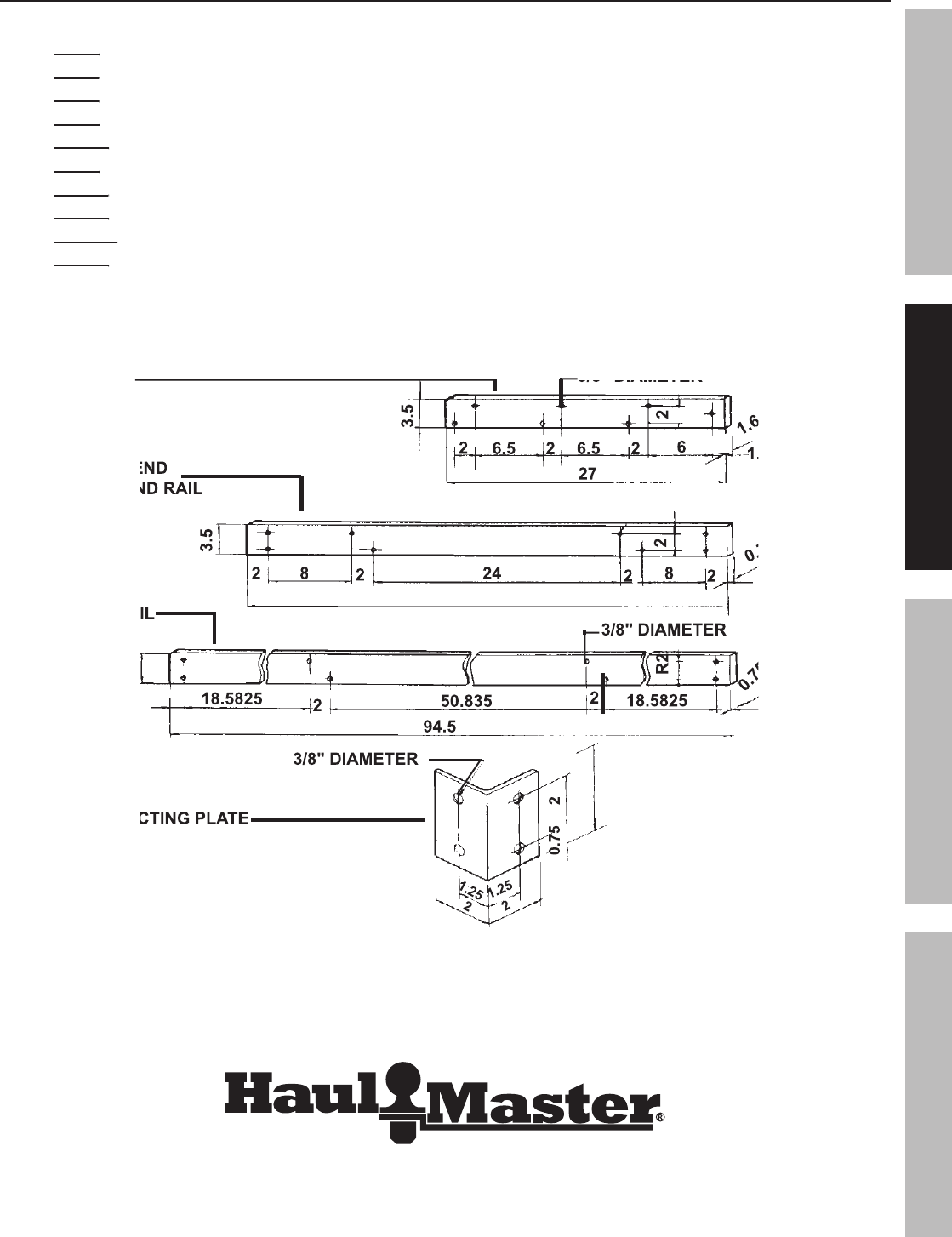
Optional Rail Installation (not included)
Minimum Required Parts:
a.
Qty. 8
Qty. 8
:
1.6" x 3.5" x 27" wood strips (not included).
b.
Qty. 6
Qty. 6
:
0.75" x 3.5" x 48" wood strips (not included).
c.
Qty. 6
Qty. 6
:
0.75" x 3.5" x 94.5" wood strips (not included).
d.
Qty. 4
Qty. 4
: 0.175" x 2" x 2" x 3.5" Steel Angle (not included).
e.
Qty. 16
Qty. 16
:
3/8" x 1-3/4" Bolt (not included).
f.
Qty. 8
Qty. 8
:
3/8" x 2-3/8" Bolt (not included).
g.
Qty. 48
Qty. 48
:
3/8" x 2-3/8" Bolt (not included).
h.
Qty. 72
Qty. 72
:
3/8" Spring Washer (not included).
i.
Qty. 112
Qty. 112
:
3/8" Flat Washer (not included).
j.
Qty. 72
Qty. 72
:
3/8" Nut (not included).
1.
Cut the Stakes, Front End Rails, Back End Rails, and Side rails to the sizes indicated
in Figure
L and drill 3/8" diameter mounting holes where shown.
3/8" DIAMETER
3/8" DIAMETER
2
1.6
1.6
0.75
0.75
0.75
0.75
3/8" DIAMETER
1.25
1.25
2
2
0.75
2
94.5
1.25
R2
18.5825
2
50.835
2
18.5825
3.5
3/8" DIAMETER
2
8
2
24
2
8
2
3.5
2
27
1.25
1.25
6
2
6.5
2
6.5
2
3.5
SIDE RAIL
SIDE RAIL
STAKE
FRONT END
FRONT END
BACK END RAIL
BACK END RAIL
CONNECTING PLATE
CONNECTING PLATE
Figure
L:
Stake Dimensions and Hole Locations
Page 16
For technical questions, please call 1-800-444-3353.
Item 69897
SAFETY OPERATION MAINTENANCEASSEMBLY
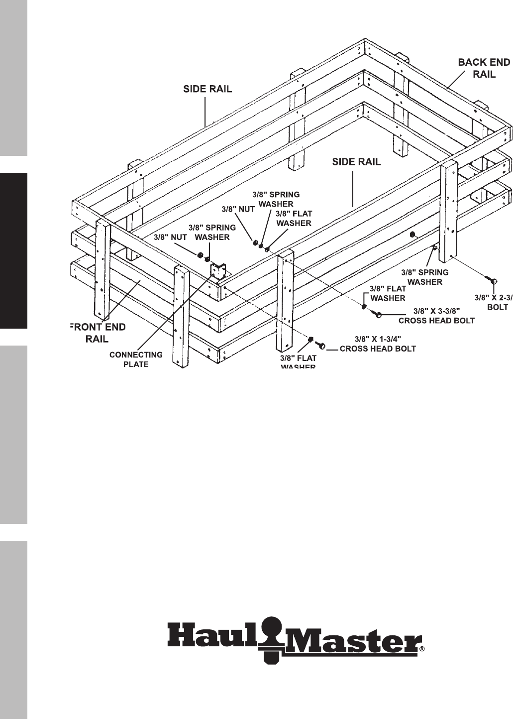
2.
Attach the Side Rails and Front End/Back End Rails
to the Stakes, using
3/8"
x
3-3/8"
Cross
Head
Bolts,
3/8" Flat Washers, and 3/8" Nuts.
3.
Attach the Connecting Plates to the
Side
Rails and Front End/Back End Rails,
using
3/8"
x
1-3/4"
Cross Head Bolts and 3/8" Nuts.
3/8" NUT
3/8" SPRING
WASHER
3/8" FLAT
WASHER
WASHER
3/8" X 1-3/4"
CROSS HEAD BOLT
3/8" NUT
3/8" SPRING
WASHER
3/8" FLAT
WASHER
3/8" SPRING
WASHER
3/8" FLAT
WASHER
3/8" X 3-3/8"
CROSS HEAD BOLT
3/8" X 2-3/8"
3/8" X 2-3/8"
BOLT
CONNECTING
PLATE
FRONT END
FRONT END
RAIL
BACK END
RAIL
SIDE RAIL
SIDE RAIL
Figure
M:
Stake Assembly
Page 17
For technical questions, please call 1-800-444-3353.
Item 69897
SAFETYOPERATIONMAINTENANCE ASSEMBLY
Specifications
Maximum Capacity Payload
Maximum Capacity Payload
1,720 lb.
Bed Dimensions
4 Ft. x 8 Ft.
Hitch Ball Size
2"
Wheel Rim Diameter/Width
12" x 4"
Quantity Wheel Lug Nuts
Quantity Wheel Lug Nuts
5 Per Wheel
Tire Size
5.30-12
Required Tire Air Pressure
Required Tire Air Pressure
80 PSI, Cold
Hitch Class
II
Operating Instructions
Read the
ENTIRE
IMPORTANT SAFETY INFORMATION
section at the beginning of this
manual including all text under subheadings therein before set up or use of this Trailer.
Before each use
1.
Check Tire condition and air pressure.
2.
Make sure wheel lug nuts/bolts
are properly tightened.
3.
Make sure hitch, coupler, draw bar, and other
equipment that connect the trailer and the tow
vehicle are properly secured and adjusted.
4.
Make sure wiring is properly connected —
not
touching the
road, but
loose enough to make
turns without disconnecting or damaging the wires.
5.
Make sure all running lights, brake lights,
turn
signals, and hazard lights are working.
6.
Check that all items are securely
fastened on and in the trailer.
7.
Be sure the trailer jack, tongue support, and any
attached stabilizers are raised and locked in place.
8.
Check load distribution to make sure
the tow vehicle and trailer are properly
balanced front to back and side to side.
9.
Check side- and rear-view mirrors to
make sure you have good visibility.
10.
Check routes and restrictions on bridges and tunnels.
11.
Make sure you have wheel chocks and jack stands.
12.
Check trailer for loose bolts and nuts,
structural
cracks and bends, and any other
condition that may affect its safe operation.
Do
not
use
the
Trailer even if minor damage appears.
Page 18
For technical questions, please call 1-800-444-3353.
Item 69897
SAFETY OPERATION MAINTENANCEASSEMBLY
Connection
WARNING!
Only use a 2" ball hitch
(not
included) on the towing vehicle.
1.
To reduce friction between the hitch ball
and Hitch Coupler (2), apply a thin layer of
heavy weight grease over the hitch ball.
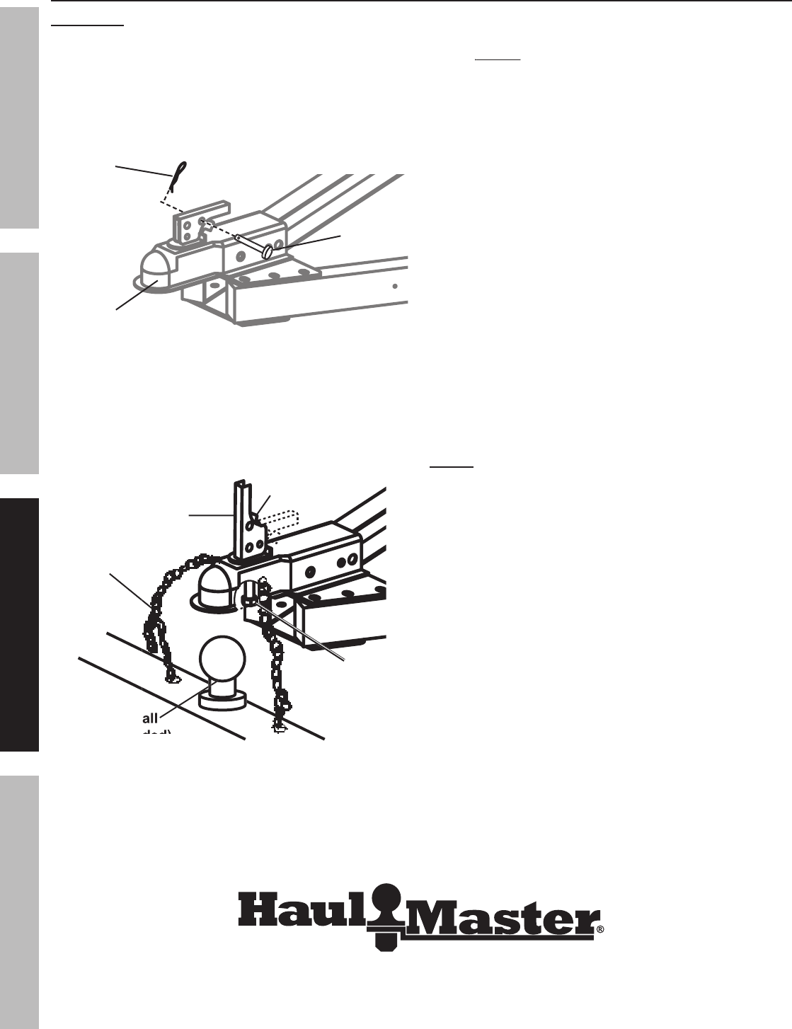
2.
Remove the R-Clip (43) and Locking Pin (47).
Hitch
Coupler (2)
Locking
Pin (47)
2 mm R-Clip (43)
Figure
N:
Remove R-Clip and Lock Pin
3.
Then, pull up on the Trigger and lift up on the Handle.
4.
With assistance, place the Hitch Coupler
over the vehicle’s hitch ball and pull back on
the Trigger and push down on the Handle
until the Trigger locks in the
slot.
Hitch Ball
Hitch Ball
(not included)
(not included)
Handle
Trigger
Adjusting
Nut
Safety
Chain (1)
Figure
O:
Ball Connection
5.
Pull up and down on the Coupler to make sure the
hitch ball is fitting snugly in the Coupler. There must
be
no play
no play
between the hitch ball and Coupler.
WARNING!
If there is play, tighten the Adjusting
Nut
until no play is present.
After unlocking the Handle, the Nut retaining
plate
(holding the Adjusting
Nut in place) needs to be
pressed back while the Nut is tightened. After
Nut
is tightened,
the retaining plate needs to t in
place against the ats of the Nut to prevent
it from moving
. This
adjustment
should
be
done by two people. If the Adjusting
Nut
is too tight, the Handle will not lock.
6.
After the Adjusting Nut is properly adjusted,
pull back on the Trigger and push down on
the Handle until the Trigger locks in the slot.
Pull
up
on
Handle firmly
to make sure the Trigger
is locked in place and the Handle cannot
move.
Replace the Locking
Pin and 2mm R-Clip.
7.
Attach each side of the Safety
Chain (1) equally
to the towing vehicle’s rear bumper or frame.
8.
Connect the Wiring Harness to the
towing vehicle’s 12 Volt DC system.
NOTE:
Consult the operator’s manual of the towing
vehicle for proper connection instructions.
9.
When towing the Trailer over long
distances stop and check the tightness of
all connections, Side Running Lights (45),
and
Tail
Lights
(23L,
23R)
at least
every 100 miles.
at least every 100 miles.at least
10.
Carry emergency flares and fire extinguisher,
if required for operation in your state.
Carry extra bulbs and fuses if towing the
Trailer at night over long distances.

Page 19
For technical questions, please call 1-800-444-3353.
Item 69897
SAFETYOPERATIONMAINTENANCE ASSEMBLY
Tire information
Tire Terminology Glossary
•
Accessory weight means
Accessory weight means
- the combined weight
of automatic transmission, power steering,
power brakes, power windows, power seats,
radio, and heater, to the extent that these items
are available as factory-installed equipment.
•
Carcass means
- the tire structure except for the
tread which provides the major portion of the tire’s
capability to deflect in response to the vertical loads
and tractive forces that the tire transmits from the
roadway to the non-pneumatic rim, the wheel center
member, or the vehicle and which attaches to the
vehicle or attaches, either integrally or separably, to
the wheel center member or non-pneumatic rim.
•
Carcass separation means
Carcass separation means
- the pulling
away of the carcass from the non
-
pneumatic
rim or wheel center member.
•
Chunking means
Chunking means
- the breaking away
of pieces of the carcass or tread.
•
Cracking means
Cracking means
- any parting within the
carcass, tread, or any components that connect
the tire to the wheel center member.
•
Curb weight means
Curb weight means
- the weight of a motor vehicle
with standard equipment including the maximum
capacity of fuel, oil, and coolant, and, if so equipped,
air conditioning and additional weight optional engine.
•
Load rating means
Load rating means
- the maximum
load a tire is rated to carry.
•
Maximum loaded vehicle weight
Maximum loaded vehicle weight
means
- the sum of:
a.
Curb weight;
b.
Accessory weight;
c.
Vehicle capacity weight; and
d.
Production options weight.
•
Maximum tire width means
- the greater of either
the linear distance between the exterior edges
of the carcass or the linear distance between
the exterior edges of the tread, both being
measured parallel to the rolling axis of the tire.
•
Normal occupant weight means
Normal occupant weight means
-
68
kilograms
times the number of occupants.
•
Occupant distribution means
Occupant distribution means
-
distribution of occupants in a vehicle.
•
Production options weight means
Production options weight means
- the combined
weight of those installed regular production options
weighing over 2.3 kilograms in excess of those
standard items which they replace, not previously
considered in curb weight or accessory weight,
including heavy duty brakes, ride levelers, roof
rack, heavy duty battery, and special trim.
•
Tread means
- that portion of the tire that
comes in contact with the road.
•
Tread separation means
Tread separation means
- pulling away
of the tread from the carcass.
•
Vehicle capacity weight means
Vehicle capacity weight means
- the rated
cargo and luggage load plus 68 kilograms times
the vehicle’s designated seating capacity.
•
Vehicle maximum load on the tire means
- that
load on an individual tire that is determined by
distributing to each axle its share of the maximum
loaded vehicle weight and dividing by two.
•
Vehicle normal load on the tire means
- that
load on an individual tire that is determined
by distributing to each axle its share of the
curb weight, accessory weight, and normal
occupant weight and dividing by 2.
Page 20
For technical questions, please call 1-800-444-3353.
Item 69897
SAFETY OPERATION MAINTENANCEASSEMBLY
Tire Markings
Load index and
Speed rating*
European tire
certificate*
U.S. DOT tire
identification
number
*Information not required by U.S. DOT
Inner diameter
in inches
Section width
in inches
Trailer
tire
Maximum
load rating
Tire ply
composition
and materials
used
Maximum
permissible
inflation
pressure
•
Section width
- This number gives the width of the
tire in inches. The larger the number, the wider
the
tire. (The markings on the example tire diagram
show 4.80. The markings on your tire may differ.)
•
Inner diameter
- This number gives the
inner
diameter of the tire in inches.
This is also the rim diameter in inches.
(The markings on the example tire diagram show 12.
The
markings on your tire may differ.)
•
U.S. DOT tire identification number
-
This
begins with the letters “DOT" and indicates that
the tire meets all federal standards.
The next two numbers or letters are the plant
code
where it was manufactured, and the last four
numbers represent the week and year that the tire
was built. For example, the numbers 2107 mean
the 21st week of 2007. Any other numbers used
are marketing codes used at the manufacturer’s
discretion. This information is used to contact
consumers if a tire defect requires a recall.
•
Maximum Load Rating
Maximum Load Rating
- This number
indicates the maximum load in kilograms and
pounds that can be carried by the tire.
•
Load index
- This is a measurement of how much
weight each tire can support. See chart below.
(The markings on the example tire diagram show 71.
The markings on your tire may differ.)
Note:
You may not find this information on
You may not find this information on
all tires because it is not required by law.
Code
Pounds
71
761
72
783
73
805
74
827
75
853
76
882
77
908
78
937
Code
Pounds
79
963
80
992
81
1,019
82
1,047
83
1,074
84
1,102
85
1,135
86
1,168
Code
Pounds
87
1,201
88
1,235
89
1,279
90
1,323
91
1,356
92
1,389
93
1,433
94
1,477
Code
Pounds
95
1,521
96
1,565
97
1,609
98
1,653
99
1,709
100
1,764
101
1,819
102
1,874
Code
Pounds
103
1,929
104
1,984
105
2,039
106
2,094
107
2,149
108
2,205
109
2,271
110
2,337
Table
A:
Load Index Rating
Codes
Page 21
For technical questions, please call 1-800-444-3353.
Item 69897
SAFETYOPERATIONMAINTENANCE ASSEMBLY
•
Speed Rating
Speed Rating
- The speed rating denotes the
speed at which a tire is designed to be driven for
extended periods of time.
This does not indicate
that the vehicle or rims can safely reach or
maintain
that
speed.
These ratings are listed below.
(The markings on the example tire diagram show M.
The markings on your tire may differ.)
Note:
You may not find this information on
all tires because it is not required by law.
Code
MPH
F
50
G
56
J
62
K
68
L
75
M
81
Code
MPH
N
87
P
94
Q
100
R
106
S
112
T
118
Code
MPH
U
124
H
130
V
149
Z
149
W
168
Y
186
Table
B:
Tire Speed Rating Codes
•
Tire Ply Composition and Materials Used
Tire Ply Composition and Materials Used
-
The
number of plies indicates the number of layers of
rubber-coated fabric in the tire.
In
general, the greater the number of plies, the
more
weight a tire can support. Tire manufacturers
also must indicate the materials in the tire, which
include steel, nylon, polyester, and others.
•
Maximum Permissible Inflation Pressure
-
This number is the greatest amount of air
pressure that should ever be put in the
tire under normal driving conditions.
Tire Inflation and Load Limit
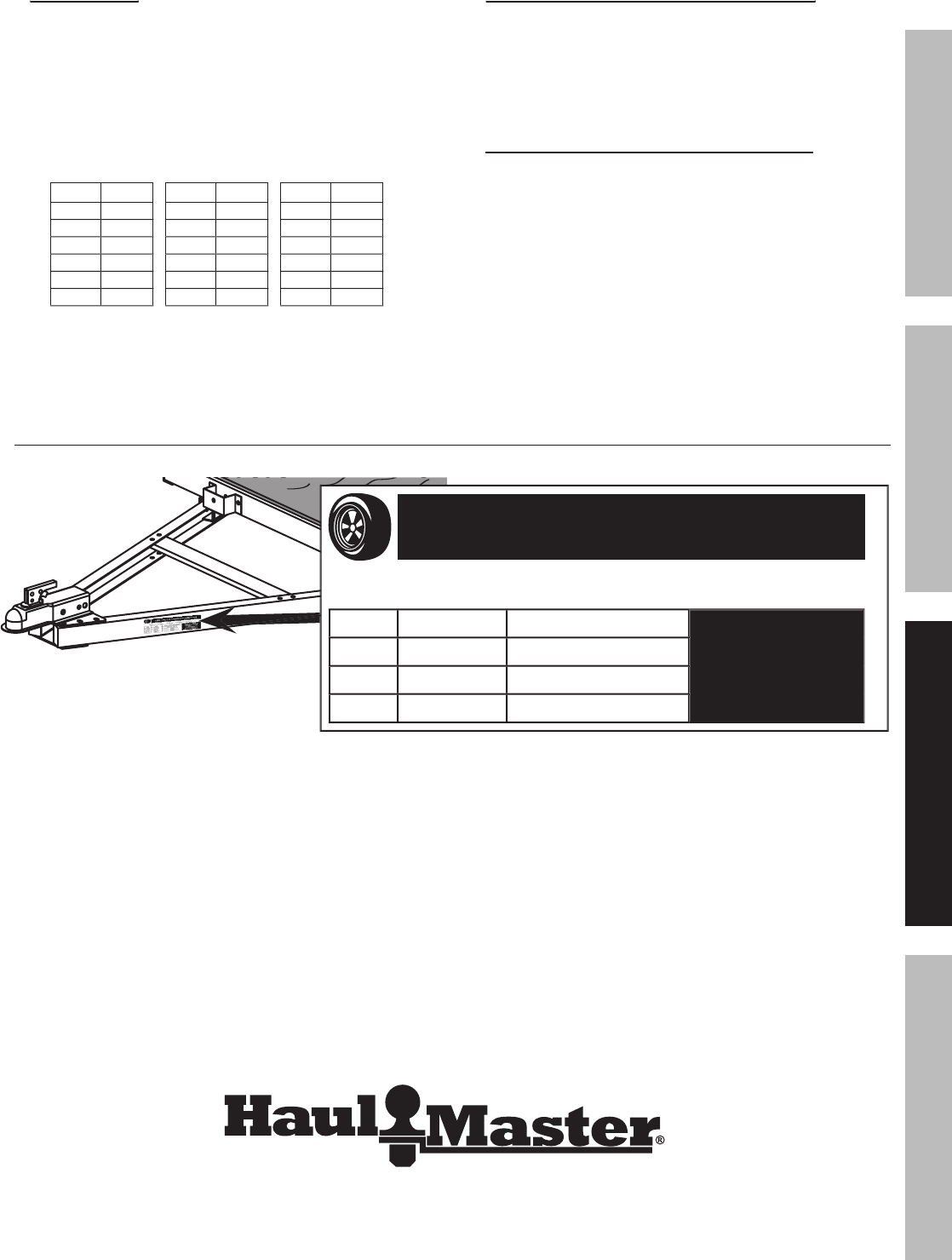
Tire and Loading Information Placard
TIRE AND LOADING INFORMATION
The weight of cargo should never exceed 780 kg or 1720 lb.
TIRE
SIZE
COLD TIRE PRESSURE
SEE OWNER’S
MANUAL FOR
ADDITIONAL
INFORMATION.
FRONT
5.30-12
550 kPa, 80 PSI
REAR
NONE
NONE
SPARE
NONE
NONE
13a
MODEL 69897
Figure
P:
Tire and Loading Information Placard Location
The Tire and Loading Information Placard displays the cold tire inflation pressure and the load limit
for this vehicle. See the Tire Care section starting on the following page for an explanation of tire
pressure and see the Vehicle Load Limit following that for an explanation of load limit.

Page 22
For technical questions, please call 1-800-444-3353.
Item 69897
SAFETY OPERATION MAINTENANCEASSEMBLY
Tire care
Checking Tire Pressure
Note:
Underinflated tires can decrease handling,
Underinflated tires can decrease handling,
stopping performance, traction, tire life, and load
-
carrying
capability, in addition to causing other negative and
hazardous effects, including
tire
failure. Overinflated
tires are at greater risk of an impact break, where the
tread and casing break when striking a hard edge,
often opening a huge gash across the tread. Incorrect
inflation pressure also increases tires wear rate.
Therefore, it is important to keep tires inflated properly.
Check all tires’ pressure at least monthly,
due to the following factors:
•
Most tires naturally lose air gradually.
•
Tires can suddenly lose air if the tire
strikes a pothole, curb, or other object.
•
It is usually not possible to determine
underinflation of radial tires by visual inspection.
This vehicle has 80 PSI recommended cold tire inflation
pressure. The term “cold" in this manual does not
refer to the temperature outside, but it refers to the
fact that a tire that has not been driven for a period is
cooler (and therefore has lower pressure) than a tire
that has been driven on. Tires heat up while being
driven on. To check (or fill to) a tire’s cold inflation,
the tire must have not been driven for more than a
mile or two for at least three hours. If you check a
tires pressure when it is not “cold", the pressure will
appear higher than the actual cold tire inflation.
Steps for Maintaining Proper Tire Pressure
1.
Locate the recommended tire pressure on the
vehicle’s tire information placard, certification
label, or in the owner’s manual. This Trailer has
80 PSI recommended cold tire inflation pressure.
2.
Measure and record the tire pressure of all tires.
3.
If the tire pressure is too high in any of the tires
and the tires have not been driven for at least
three hours, slowly release air by gently pressing
on the tire valve stem with the edge of your
tire gauge until you get to the correct pressure.
If
the
vehicle
has
been driven within the past three
hours and the tire pressure is too high on any tires,
then recheck the pressure once the tires have been
allowed to sit motionless for at least three hours.
4.
If the tire pressure is too low, note the difference
between the measured tire pressure and the
correct tire pressure. These “missing" pounds
of pressure are what you will need to add.
5.
At a service station, add the missing pounds of
air pressure to each tire that is underinflated.
6.
Check all the tires to make sure they
have the same air pressure.
7.
If the tires’ pressure was not measured “cold",
then the pressure should be rechecked
with the tires cold as soon as possible.
Tire Size
To maintain safety, only purchase new tires of the same size as the original tires.
Look at the Tire and Loading Information Placard, the Specifications Chart in this manual, or the sidewall
of the tire being replaced. If you have any doubt about selecting the correct size, consult a tire dealer.
Tire Tread
The tire tread provides traction that prevents your vehicle from slipping, especially if the road is wet or icy.
Tires are unsafe and should be replaced when the tread is worn down to 1/16".
Measure tread depth using a tread depth indicator (not included).
Tire Rotation
Every 5,000 miles the left and right tires should be switched.
This will cause the tires to wear more evenly and last longer.

Page 23
For technical questions, please call 1-800-444-3353.
Item 69897
SAFETYOPERATIONMAINTENANCE ASSEMBLY
Tire Balance and Alignment
The tires need to be balanced to prevent vibration when driving. This involves attaching small weights to the
rim to offset small differences in rim and tire weight. The tires also need to be aligned properly. Alignment is the
orientation of the tires to the road surface and their being parallel. This helps the tires to wear evenly, and provide
better traction. Both tire balance and alignment require specialized equipment that is not provided with this vehicle.
Tire Repair
To properly repair a punctured tire, the hole needs to be properly plugged and patched from the inside of the tire.
Tread punctures can be repaired if they are not too large. Sidewall punctures should not be repaired, the tire needs to
be replaced if the sidewall is damaged. Tires should be removed from the rim to be inspected before being plugged
and patched. A qualified mechanic should remove the tire from the rim, perform the repair, and remount the tire.
Vehicle Load Limit
Steps for Determining Correct Load Limit
1.
Locate the statement “The weight of cargo
should never exceed 780 kilograms or 1720
pounds" on your vehicle’s placard.
2.
That figure equals the available amount
of cargo and luggage load capacity.
3.
Determine the combined weight of luggage
and cargo being loaded on the vehicle.
That
weight may not safely exceed the
available cargo and luggage load capacity.
4.
If the Trailer’s load exceeds the cargo and luggage
load capacity, then the Trailer will be unsafe resulting
in hazardous effects, such as: Trailer’s tires will
not be able to maintain traction properly, and
stopping distance will be increased significantly.
Operation Safety
Note:
Selected recommendations in this section are adapted from
Selected recommendations in this section are adapted from
TOWING
A
TRAILER
-
Being
Equipped for Safety
, published by NHTSA. For full details, see that document.
1.
This Trailer is not a toy.
Do not allow children to play on or near this item.
2.
Take time to practice before driving on main roads.
3.
Never allow anyone to ride in or on the trailer.
4.
Do not transport animals in this trailer.
General Handling
1.
Use the driving gear that the towing vehicle
manufacturer recommends for towing.
2.
Drive at moderate speeds. This will place
less strain on your tow vehicle and trailer.
Trailer
instability
(sway) is more likely to
occur as speed increases.
Do not exceed
45
miles
per hour when towing the Trailer.
3.
Avoid sudden stops and starts that can
cause skidding, sliding, or jackknifing.
4.
Avoid sudden steering maneuvers that might
create sway or undue side force on the trailer.
5.
Slow down when traveling over bumpy
roads,
railroad crossings, and ditches.
6.
Make wider turns at curves and corners.
Because your trailer’s wheels are closer to the
inside of a turn than the wheels of your tow vehicle,
they are more likely to hit or ride up over curbs.
7.
To control swaying caused by air pressure changes
and wind buffeting when larger vehicles pass from
either direction, release the accelerator pedal to slow
down and keep a firm grip on the steering wheel.
Braking
1.
Allow considerably more distance for stopping.
2.
If you have an electric trailer brake controller and
excessive sway occurs, activate the trailer brake
controller by hand. Do not attempt to control
trailer sway by applying the tow vehicle brakes;
this will generally make the sway worse.
3.
Always anticipate the need to slow
down.
To reduce speed, shift to a lower gear
and press the brakes lightly.

Page 24
For technical questions, please call 1-800-444-3353.
Item 69897
SAFETY OPERATION MAINTENANCEASSEMBLY
Acceleration and Passing
1.
When passing a slower vehicle or changing
lanes,
signal well in advance and make sure you
allow extra distance to clear the vehicle
before you pull back into the lane.
2.
Pass on level terrain with plenty of clearance.
Avoid passing on steep upgrades or downgrades.
3.
If necessary, downshift for improved
acceleration or speed maintenance.
4.
When passing on narrow roads, be careful not
to go onto a soft shoulder. This could cause
your trailer to jackknife or go out of control.
Downgrades and Upgrades
1.
Downshift to assist with braking on downgrades
and to add power for climbing hills.
2.
On long downgrades, apply brakes at intervals to
keep speed in check. Never leave brakes on for
extended periods of time or they may overheat.
3.
Some tow vehicles have specifically calibrated
transmission tow-modes. Be
sure to use the
tow
-
mode recommended by the manufacturer.
Backing Up
1.
Put your hand at the bottom of the steering wheel.
To
turn left, move your hand left.
To turn right,
move
your hand right.
2.
Back
up
slowly.
3.
Because mirrors cannot provide all of the
visibility you may need when
backing
up,
have someone outside at the rear of the
trailer to guide you whenever possible.
4.
Use slight movements of the steering wheel
to adjust direction. Exaggerated movements
will cause greater movement of the trailer.
5.
If
you have difficulty, pull forward and realign
the tow vehicle and trailer and start again.
Parking
1.
Try to avoid parking on grades.
2.
If possible, have
someone outside
to guide you as you park.
3.
Once
stopped, but before shifting into Park:
a.
Have
someone place blocks on the
downhill side of the trailer wheels.
b.
Apply the parking brake.
c.
Shift
into
Park.
(first or reverse gear for manual transmissions)
d.
Then
remove your foot from the brake pedal.
Following this parking sequence is important to
make sure your vehicle does not become locked in
Park because of extra load on the transmission.
4.
Before uncoupling a trailer:
a.
Place blocks at the front and rear of the
trailer tires to ensure that the trailer does not
roll away when the coupling is released.
b.
An unbalanced load may cause the
tongue to suddenly rotate upward;
therefore,
before
uncoupling, place jack stands
under the rear of the trailer to prevent injury.
TRAILER LICENSING NOTICE
Some
states
may
consider this Trailer a vehicle requiring registration, licensing, and titling.
Check with your State Department of Motor
Vehicles for information and
guidance on registering, licensing, and titling the Trailer.
Page 25
For technical questions, please call 1-800-444-3353.
Item 69897
SAFETYOPERATIONMAINTENANCE ASSEMBLY
Maintenance
Procedures not specifically explained in this manual must
be performed only by a qualified
technician.
TO PREVENT SERIOUS INJURY FROM TOOL FAILURE:
Do not use damaged equipment.
If
abnormal
noise or vibration
occurs, have the problem corrected before further use.
Note:
Tow vehicles often have more frequent maintenance requirements, including changes of
Tow vehicles often have more frequent maintenance requirements, including changes of
engine and transmission oils and filters, lubrication of components, and cooling system checks.
Check
your
owner’s manual for information on scheduled maintenance of your tow vehicle.
BEFORE
EACH USE:
Inspect the trailer and tow vehicle according to the instructions on page
17.
Tires
1.
Periodic inspection and maintenance of tires
and wheels are essential to towing safety,
including spare tires. Proper tire pressure affects
vehicle handling and the safety
of
your
tires.
You can find the correct tire pressure for your
tow vehicle on the tire information placard.
2.
Underinflation reduces the load-carrying capacity
of your tow vehicle or trailer, may cause sway and
control problems, and may result in overheating,
causing blowouts or other tire failure.
3.
Overinflation causes premature tire wear
and affects the handling characteristics
of the tow vehicle or trailer.
Wheel Bearings
1.
EVERY 2,000 TO 3,000 MILES OF USE,
lubricate the Hub Assemblies with a
heavy weight bearing
grease, following
Bearing
Packing
Instructions
on page
9.
2.
After each Hub Assembly is reassembled,
tighten the Castle Nut until the wheel
starts spinning with slight resistance.
Loosen
the
Castle
Nut
about 1/6 turn from this point.
3.
Insert a new Cotter Pin through the
Castle Nut and the hole in the axle.
4.
Bend the Cotter Pin back,
locking
it
and the Nut in place.
Hitch
Check the nuts, bolts, and other fasteners to ensure that the hitch remains secured to the
tow vehicle and the coupler remains secured to the trailer. The connection point may require
periodic lubrication to permit free movement of the coupler to the hitch ball.
Wiring
1.
Make sure connector-plug prongs and receptacles,
light bulb sockets, wire splices, and ground
connections are clean and shielded from moisture.
Lightly coat all electrical terminal connections with
nonconducting (dielectric), light waterproof grease.
2.
Clean the prongs with very fine sandpaper,
being careful not to damage the contact area.
3.
Turn lights off, then clean the surface deposits
in the connector holes.
Try to clean
off only the deposits and lubricate
lightly with dielectric, light waterproof grease.
Page 26
For technical questions, please call 1-800-444-3353.
Item 69897
SAFETY OPERATION MAINTENANCEASSEMBLY
Parts List and Diagram
PLEASE READ THE FOLLOWING CAREFULLY
THE MANUFACTURER AND/OR DISTRIBUTOR HAS PROVIDED THE PARTS LIST AND ASSEMBLY DIAGRAM IN
THIS MANUAL AS A REFERENCE TOOL ONLY. NEITHER THE MANUFACTURER OR DISTRIBUTOR MAKES ANY
REPRESENTATION OR WARRANTY OF ANY KIND TO THE BUYER THAT HE OR SHE IS QUALIFIED TO MAKE ANY
REPAIRS TO THE PRODUCT, OR THAT HE OR SHE IS QUALIFIED TO REPLACE ANY PARTS OF THE PRODUCT.
IN FACT, THE MANUFACTURER AND/OR DISTRIBUTOR EXPRESSLY STATES THAT ALL REPAIRS AND PARTS
REPLACEMENTS SHOULD BE UNDERTAKEN BY CERTIFIED AND LICENSED TECHNICIANS, AND NOT BY THE
BUYER. THE BUYER ASSUMES ALL RISK AND LIABILITY ARISING OUT OF HIS OR HER REPAIRS TO THE
ORIGINAL PRODUCT OR REPLACEMENT PARTS THERETO, OR ARISING OUT OF HIS OR HER INSTALLATION
OF REPLACEMENT PARTS THERETO.
Parts List
Part
Description
Qty
1
7/32" Safety Chain
1
2
Hitch Coupler
1
3
Coupler Base
1
4
Drawbar T-Plate
1
5
Drawbar Rail
2
6
Drawbar Bracket
2
7
Bolt M10
x
30
4
8
Leaf Spring
2
9
Fender Bracket
2
10
Spring Plate
2
11
Axle
1
12
Hub Assembly
2
13
5.30-12" Tire
2
14
Dust Cap
2
15
Front Left Side Rail
1
16
Bolt M12
x
75
6
17
Left Spring Hanger
1
18
Fender
2
19
Flat Washer Ø22
2
20
Rear Left Side Rail
1
21
Cross Member
5
22
Rear Right Side Rail
1
Part
Description
Qty
23L
Left Tail Light
1
23R
Right Tail Light
1
24
Light Bracket
2
25
Carriage Bolt M10
x
25
4
26
Right Spring Hanger
1
27
Front Right Side Rail
1
28
Front Member
1
29
Bolt M12
x
25
2
30
L-Latch Ø12
x
75
2
31
Bolt M10
x
20
48
32
U-Bolt M10
x
90
4
33
Nut M10
64
34
3mm R-Clip
2
35
Nut M12
8
37
Castle Nut M22
x
1.5
2
38
Cotter Pin
2
39
Bearing
4
40
Lug Nut M12
10
43
2mm R-Clip
1
44
License Plate Bracket
1
45
Side Running Light
2
46
Screw M4 x 25
4
47
Locking Pin
1
Record Product’s Serial Number Here:
Note:
If product has no serial number, record month and year of purchase instead.
If product has no serial number, record month and year of purchase instead.
Note:
Some parts are listed and shown for illustration purposes only,
Some parts are listed and shown for illustration purposes only,
and
are not available individually as replacement parts.
Page 27
For technical questions, please call 1-800-444-3353.
Item 69897
SAFETYOPERATIONMAINTENANCE ASSEMBLY
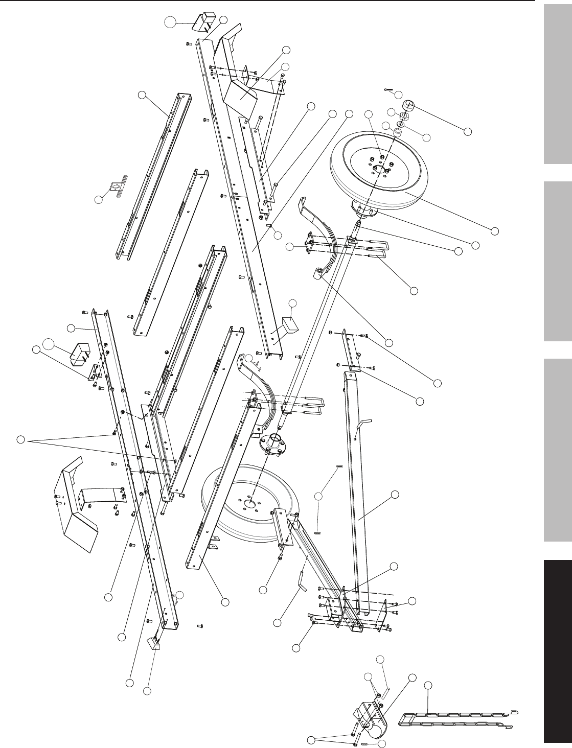
Assembly Diagram
17
2
1
5
6
31
30
29
7
11
12
13
32
8
14
16
18
15
20
21
22
24
25
7
26
27
28
3
6
16
47
35
31
7
15
25
7
4
45
45
46
9
44
46
39
37
38
34
4343
10
4040
19
23R
23L
31

3491 Mission Oaks Blvd. • PO Box 6009 • Camarillo, CA 93011 • (800) 444-3353
Reporting Safety Defects
If you believe that your vehicle has a defect which could cause a crash or could cause injury or death,
you
should immediately inform the National Traffic Safety Administration (NHTSA) in addition to notifying
Changzhou
Nanxiashu Tool Company. If NHTSA receives similar complaints, it may open an investigation.
And
if
it
finds that a safety defect exist in a group of vehicles, it may order a recall
and
remedy
campaign.
However,
NHTSA cannot become involved in individual problems between you, your dealer, or
Changzhou
Nanxiashu Tool Company. To
contact
NHTSA, you may either call the Auto Safety Hotline toll
-
free
at 1-800-424-9393 or 202-366-0123 or write to NHTSA, U. S. Department, 400 7th Street SW NSA-11,
Washington, DC 20590. You can also obtain other information about motor vehicle safety from the Hotline.
Note:
Check with your local department of Motor
Check with your local department of Motor
Vehicles for registration procedures.
Some DMV’s require the Certificate of Origin to be notarized, others do not.
Limited 90 Day Warranty
Harbor Freight Tools Co. makes every effort to assure that its products meet high quality and durability standards,
and warrants to the original purchaser that this product is free from defects in materials and workmanship for the
period of 90 days from the date of purchase. This warranty does not apply to damage due directly or indirectly,
to misuse, abuse, negligence or accidents, repairs or alterations outside our facilities, criminal activity, improper
installation, normal wear and tear, or to lack of maintenance. We shall in no event be liable for death, injuries
to persons or property, or for incidental, contingent, special or consequential damages arising from the use of
our product. Some states do not allow the exclusion or limitation of incidental or consequential damages, so the
above limitation of exclusion may not apply to you.
THIS WARRANTY IS EXPRESSLY IN LIEU OF ALL OTHER
WARRANTIES, EXPRESS OR IMPLIED, INCLUDING THE WARRANTIES OF MERCHANTABILITY AND FITNESS.
To take advantage of this warranty, the product or part must be returned to us with transportation charges
prepaid. Proof of purchase date and an explanation of the complaint must accompany the merchandise.
If our inspection verifies the defect, we will either repair or replace the product at our election or we may
elect to refund the purchase price if we cannot readily and quickly provide you with a replacement. We will
return repaired products at our expense, but if we determine there is no defect, or that the defect resulted
from causes not within the scope of our warranty, then you must bear the cost of returning the product.
This warranty gives you specific legal rights and you may also have other rights which vary from state to state.
