Harbor Freight 2 Ton Capacity Foldable Shop Crane Product Manual
Manual for the 69514 SHOP CRANE, 2 TON FOLDABLE 69514 2 ton Capacity Foldable Shop Crane
2015-05-27
: Harbor-Freight Harbor-Freight-2-Ton-Capacity-Foldable-Shop-Crane-Product-Manual-723644 harbor-freight-2-ton-capacity-foldable-shop-crane-product-manual-723644 harbor-freight pdf
Open the PDF directly: View PDF ![]() .
.
Page Count: 24

Page 2 For technical questions, please call 1-888-866-5797. Item 69514
Table of Contents
Safety ......................................................... 2
Specifications ............................................. 4
Setup .......................................................... 4
Operation .................................................... 7
Maintenance ............................................... 8
Parts Lists and Diagrams .......................... 10
Warranty .................................................... 12
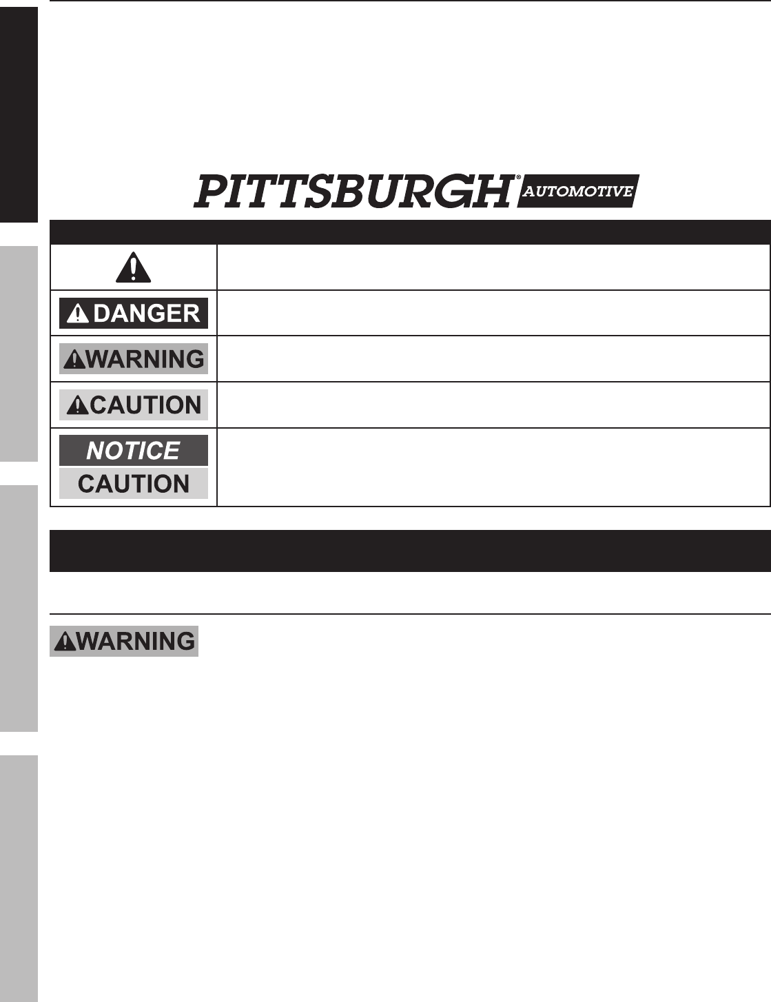
WARNING SYMBOLS AND DEFINITIONS
This is the safety alert symbol. It is used to alert you to potential personal injury hazards.
Obey all safety messages that follow this symbol to avoid possible injury or death.
Indicates a hazardous situation which, if not avoided,
will result in death or serious injury.
Indicates a hazardous situation which, if not avoided,
could result in death or serious injury.
Indicates a hazardous situation which, if not avoided,
could result in minor or moderate injury.
Addresses practices not related to personal injury.
IMPORTANT SAFETY INFORMATION
General Safety Warnings
Read all safety warnings and instructions.
Failure to follow the warnings and instructions may result in serious injury.
Save all warnings and instructions for future reference.
1. Study, understand, and follow all instructions
before operating this device.
2. Do not exceed 2 ton rated capacity
for the Engine Crane.
3. Use only on hard, level surfaces.
4. Before moving, lower the load to
the lowest possible point.
5. Use only sling or chains with a rated capacity
greater than the weight of the load being lifted.
6. Do not allow load to swing or drop
violently while lowering or moving.
7. Do not make any alterations or modifications to
Engine Crane. Do not adjust safety valve.
8. Properly extend leg extensions and secure
boom in proper setting before use.
9. Follow capacities marked on boom; capacity
decreases as boom lengthens.
10. Wear ANSI-approved safety goggles and
heavy-duty work gloves during use.
11. Verify replacement jack has same rating,
mounting points and maximum length.
12. Do not use for aircraft purposes.
SAFETY OPERATION MAINTENANCESETUP

Page 3For technical questions, please call 1-888-866-5797.Item 69514
13. Inspect before every use; do not use
if parts loose or damaged.
14. Keep your work area clean and well lit.
Cluttered work areas invite accidents.
15. Keep bystanders, children, and visitors away
while operating Engine Crane. Distractions
can cause you to lose control.
16. Stay alert. Watch what you are doing, and use
common sense when operating a jack. Do not use
a jack while tired or under the influence of drugs,
alcohol, or medication. A moment of inattention while
operating jacks may result in serious personal injury.
17. Follow instructions in the “Inspection, Maintenance,
And Cleaning” section of this manual. Use
of unauthorized parts or failure to follow
maintenance instructions may create a risk of
injury and may void any applicable warranty.
18. Maintain labels and nameplates on the
Engine Crane. These carry important
information. If unreadable or missing, contact
Harbor Freight Tools for a replacement.
19. Before use, read manufacturer’s instruction
manual for the object you will lift.
20. Industrial applications must follow
OSHA requirements.
21. The warnings, precautions, and instructions
discussed in this manual cannot cover all possible
conditions and situations that may occur. The
operator must understand that common sense and
caution are factors, which cannot be built into this
product, but must be supplied by the operator.
SAVE THESE INSTRUCTIONS.
SAFETYOPERATIONMAINTENANCE SETUP
Page 4 For technical questions, please call 1-888-866-5797. Item 69514
Specifications
Specifications
Jack Capacity 8 Ton
Boom Positions
2 Ton 84 IN.
1-1/2 Ton 89 IN.
1 Ton 95 IN.
1/2 Ton 100 IN.
Meets 2005 ANSI/ASME PALD standards.
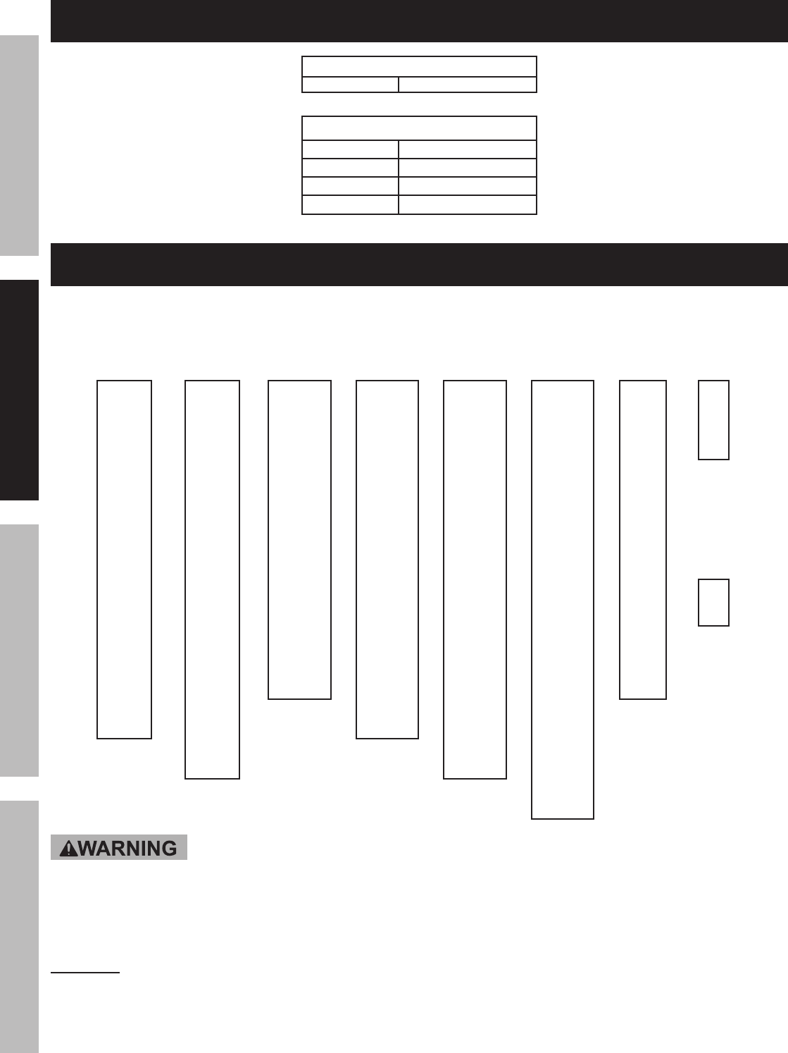
Assembly
Part
#32
14x90
mm
Part
#8
14x100
mm
Part
#11
16x80
mm
Part
#20
16x90
mm
Part
#15
16x100
mm
Part
#16
16x110
mm
Part
#2
12x80
mm
Part
#25
8x20
mm
Part
#29
8x12
mm
TO PREVENT SERIOUS INJURY AND DEATH: The correct bolts must be used during
assembly. Carefully compare bolts to Bolt Identification illustration above and the measurements shown in
the parts list and assembly diagrams near the end of this manual to make sure that the correct bolts are used
in the correct place.
WARNING! For safety and ease of assembly, use two people to assemble the Shop Crane.
CAUTION! DO NOT TIGHTEN ANY BOLTS UNTIL YOU ARE FULLY FINISHED WITH ASSEMBLY.
OTHERWISE PARTS WILL NOT LINE UP PROPERLY.
SAFETY OPERATION MAINTENANCESETUP
Page 5For technical questions, please call 1-888-866-5797.Item 69514
1.
2 5
2 4
2 3
2 2
3 0
2 1 2 6
2 7
2 8 2 92 3
Figure A
(Assembled)
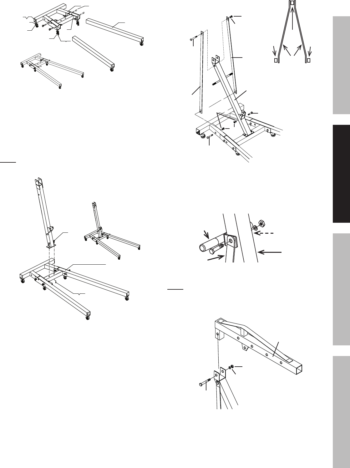
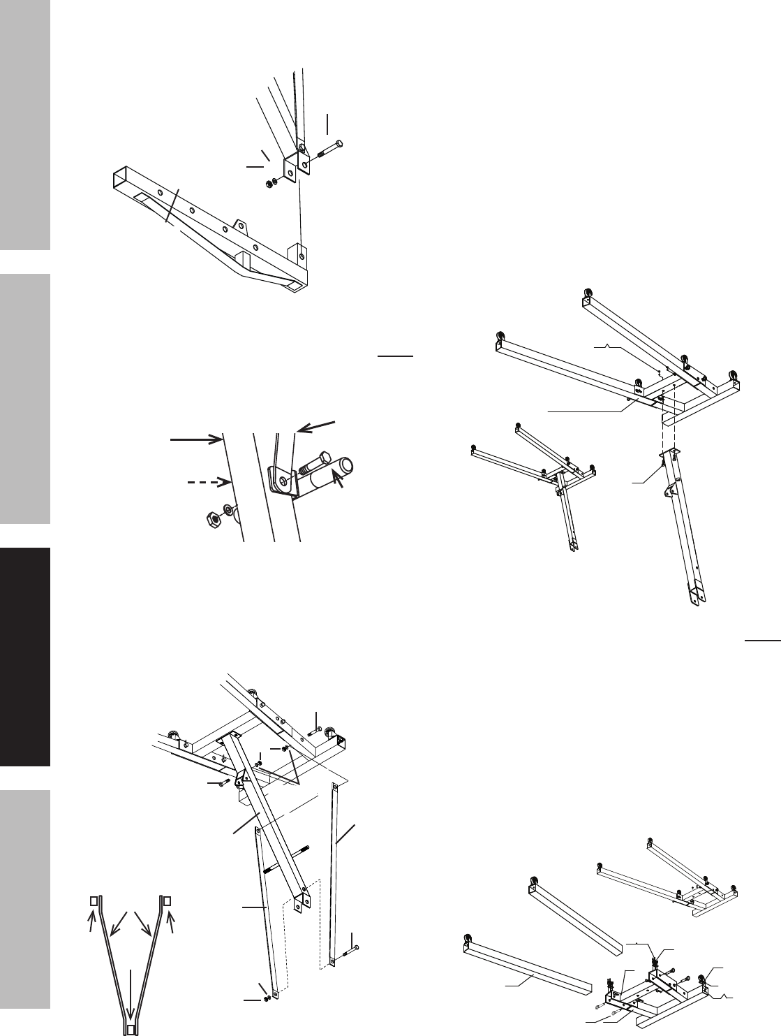
Slide the Legs into the front of the Base
and Lock Legs in place using the Lock Pins.
To insert the Lock Pins, lift up on front of Base
until holes line up. After all four Lock Pins are
inserted, insert one R-Pin through small hole at
end of each Lock Pin until it snaps into place.
Note: Make sure Lock Pins are
secure before proceeding.
2.
Base Assembly
9 10
8
(Assembled)
Figure B
Use the Bolts, Washers, and Nuts to secure the
bottom of the Post to the Base.
3.
Figure C
Washer
Washers
Nut
Nut
Post
Support
Bolt (15)
Bolt (15)
Bolt (16)
The bends of the
Supports face out
at the top and in
at the bottom as
shown above.
Support
Post
Leg Leg
Support
Use two Bolts, Washers and Nuts to fasten the lower
ends of the Supports to the inside of the Frame,
then use one Bolt, Washer and Nut to fasten the top
ends of the Supports and the Handle to the Post.
Handle
Post
Support
Support
(Not shown)
Figure D
Note: Slide the Handle between the Supports
and Post, align all holes, then secure in place.
4.
Figure E
Washer
Boom
Nut
Bolt (16)
Use the Bolt, Washer and Nut to attach
the Boom to the top of the Post.
SAFETYOPERATIONMAINTENANCE SETUP
Page 6 For technical questions, please call 1-888-866-5797. Item 69514
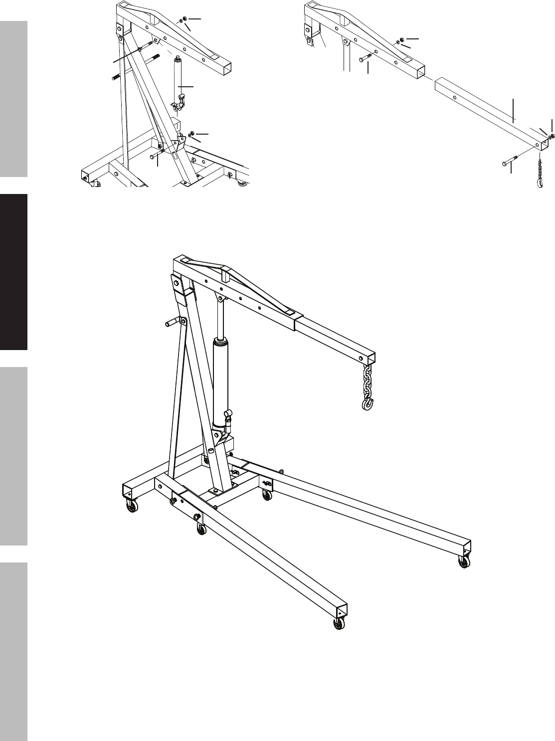
5.
Figure F
Washer
Washer
Nut
Nut
Jack
Bolt (20)
Bolt (11)
Use a Bolt, Washer and Nut to attach lower end of
the Jack to the Post and another Bolt, Washer and
Nut to attach the top of the Jack to the Boom.
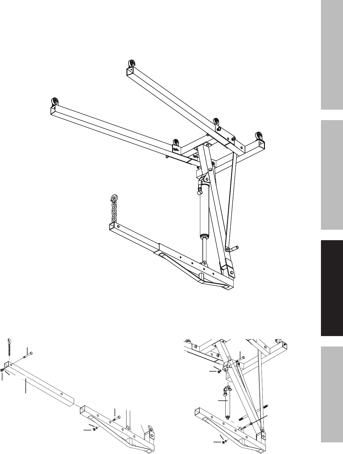
6.
Figure G
Washer
Washer
Nut
Nut
Boom Extension
Bolt (2)
Bolt (32)
Slide the Boom Extension into the Boom and use the
Bolt, Washer and Nut to secure at the desired load
rating. Use the Bolt, Washer and Nut to attach the
Hook and Chain to the end of the Boom Extension.
Figure H: Assembled Engine Crane
SAFETY OPERATION MAINTENANCESETUP
Page 7For technical questions, please call 1-888-866-5797.Item 69514
Operating Instructions
Read ENTIRE IMPORTANT SAFETY INFORMATION section at beginning of this manual
including all text under subheadings therein before set up or use of this product.
Note: Once Assembly is complete, tighten ALL Bolts before initial operation.
Lifting and Lowering
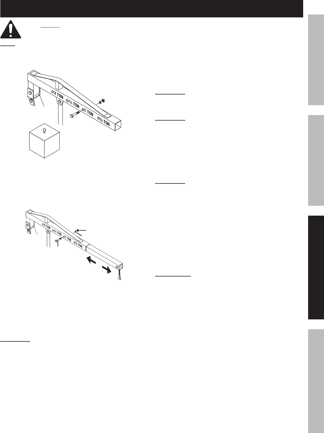
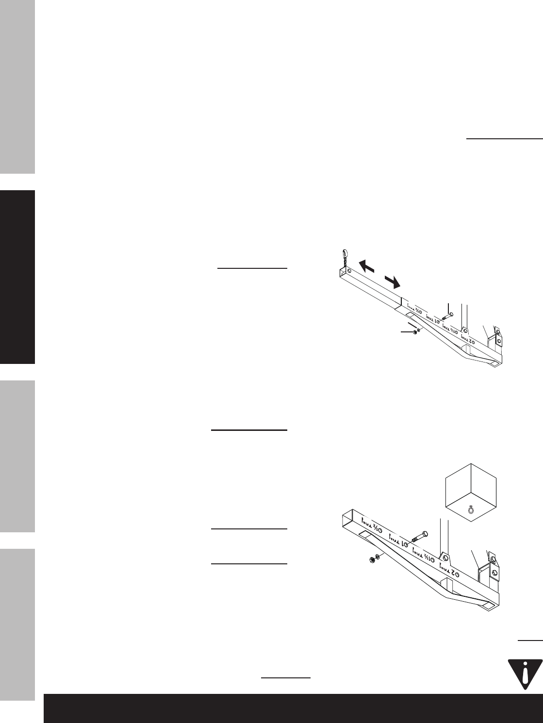
1.
3/4 Ton Load
Figure I
Locate the hole on the Boom with a weight limit
higher than the weight you will be lifting.
For example: Locate the 1 TON hole on the Boom
for a load that is under one Ton. See Figure 9.
2.
Figure J
Washer
Nut
Bolt
Adjust the Boom Extension
so the hole furthest from the
hook-end aligns with the chosen hole on the
Boom. Secure into place by inserting the Bolt
through all aligned holes and tightening in place
with the Washer and Nut. See Figure 10 above.
WARNING! Do not stand under an object that is
being lifted by the Engine Crane. Be aware of the
possibility of a load slipping off the Hook and Chain. An
item that falls from the Crane can cause serious injury.
3. Move the Crane so that the Hook and Chain
is directly above the item to be lifted.
4. Securely attach the Hook and Chain to the item.
5. To raise the Boom, turn the Jack’s release valve
fully clockwise (right). Insert the Handle into the
Jack and pump (up and down) repeatedly until
the item has been lifted to the desired height.
WARNING! Fully tighten the release valve
or else the Jack may lower or may not
be able to reach the full height.
WARNING! DO NOT MOVE THE CRANE WHEN
UNDER LOAD. The Casters are not designed to
be rolled when the Crane is lifting heavy objects.
6. To lower the Crane, SLOWLY turn the Jack’s
release valve counterclockwise (left).
Folding the Frame
WARNING! Do not fold crane while loaded.
1. Lower Crane all the way.
2. Remove R-Pins from the front Lock Pins. Remove
the front Lock Pins. Leave rear Lock Pins in.
3. Raise Leg until it rests against Handle.
4. Insert a front Lock Pin into the middle hole of
the Base, for each Leg, and reinsert R-Pins.
Bleeding Instructions
IMPORTANT! Before first use, check for proper
hydraulic oil level and thoroughly test the
equipment. If it does not work properly, bleed
excess air from its hydraulic system as follows:
1. Open Release Valve and lower Jack completely.
2. Remove Oil Plug and fill with hydraulic
oil (sold separately) to full level.
3. Apply downward pressure to the Boom and
Pump the Jack Handle quickly several times.
4. Check the Oil Fill Hole and, if necessary, top
off the Oil Fill Hole with hydraulic oil.
5. Replace the Oil Plug and close the Release Valve.
6. Test the equipment several times for proper operation
before attempting to lift a load. If, after bleeding,
the equipment still does not appear to be working
properly, do not use the equipment until it has
been repaired by a qualified service technician.
SAFETYOPERATIONMAINTENANCE SETUP

Page 8 For technical questions, please call 1-888-866-5797. Item 69514
Maintenance and Servicing
Procedures not specifically explained in this
manual must be performed only by a
qualified technician.
TO PREVENT SERIOUS INJURY
FROM ACCIDENTAL OPERATION:
Do not use damaged equipment. If abnormal
noise or vibration occurs, have the problem
corrected before further use.
Cleaning, Maintenance, and Lubrication
1. Before each use, inspect the general condition
of the Jack. Check for broken, cracked, or bent
parts, loose or missing parts, and any condition that
may affect the proper operation of the product. If a
problem occurs, have the problem corrected before
further use.
Do not use damaged equipment.
2. Before each use, thoroughly test the Jack
for proper operation prior to its actual use. If
the Jack appears not to be working properly,
follow Bleeding instructions on page 9.
3. Change the hydraulic oil at least
once every three years:
a. With the Jack fully lowered, remove the Oil
Filler Plug on the side of the Housing.
b. Tip the Jack to allow the old hydraulic oil
to drain out of the Housing completely,
and dispose of the old hydraulic oil in
accordance with local regulations.
c. With the Jack upright, completely fill the Housing
with a high quality hydraulic oil (not included) until
the oil just begins to run out of the Oil Fill Hole.
d. Open the valve Release Screw and pump
the Handle to bleed air from the system.
e. Reinstall the Oil Filler Plug.
4. Wipe dry with a clean cloth. Then, store the
Jack in a safe, dry location out of reach of
children and other non-authorized people.
SAFETY OPERATION MAINTENANCESETUP

Page 9For technical questions, please call 1-888-866-5797.Item 69514
Troubleshooting
TO PREVENT SERIOUS INJURY: Use caution when troubleshooting malfunctioning
jack. Stay clear of supported load. Completely resolve all problems before use. If
solutions presented in Troubleshooting guide do not solve the problem, have a qualified technician inspect and repair
jack before use. After jack is repaired: Test it carefully without a load by raising and lowering it fully, checking
for proper operation, BEFORE RETURNING JACK TO OPERATION.
DO NOT USE A DAMAGED OR
MALFUNCTIONING JACK!
POSSIBLE SYMPTOMS
PROBABLE SOLUTION
(Make certain that the Jack
is not supporting a load
while attempting a solution.)
Jack will
not lift at
its weight
capacity
Chain
and/or
Hook
lowers
under
load
Pump
stroke
feels
spongy
Chain
and/or
Hook
will not
lift all
the way
Handle
moves
up when
Jack is
under
load
Oil
leaking
from
Filler
Plug
X X Check that Release Valve is
closed fully.
Bleed air from the system.
X X X
Valves may be blocked and may
not close fully. To flush the valves:
1. Lower the Chain / Hook
and securely close the
Release Valve.
2. Manually lift the Chain /
Hook several inches.
3. Open the release valve and
force the Chain / Hook down
as quickly as possible.
XX X
Jack may be low on oil. Check
the oil level and refill if needed.
Jack may require bleeding -
see instructions on page 9.
XUnit may have too much
hydraulic oil inside, check fluid
level and adjust if needed.
PLEASE READ THE FOLLOWING CAREFULLY
THE MANUFACTURER AND/OR DISTRIBUTOR HAS PROVIDED THE PARTS LIST AND ASSEMBLY DIAGRAM
IN THIS MANUAL AS A REFERENCE TOOL ONLY. NEITHER THE MANUFACTURER OR DISTRIBUTOR
MAKES ANY REPRESENTATION OR WARRANTY OF ANY KIND TO THE BUYER THAT HE OR SHE IS
QUALIFIED TO MAKE ANY REPAIRS TO THE PRODUCT, OR THAT HE OR SHE IS QUALIFIED TO REPLACE
ANY PARTS OF THE PRODUCT. IN FACT, THE MANUFACTURER AND/OR DISTRIBUTOR EXPRESSLY
STATES THAT ALL REPAIRS AND PARTS REPLACEMENTS SHOULD BE UNDERTAKEN BY CERTIFIED AND
LICENSED TECHNICIANS, AND NOT BY THE BUYER. THE BUYER ASSUMES ALL RISK AND LIABILITY
ARISING OUT OF HIS OR HER REPAIRS TO THE ORIGINAL PRODUCT OR REPLACEMENT PARTS
THERETO, OR ARISING OUT OF HIS OR HER INSTALLATION OF REPLACEMENT PARTS THERETO.
SAFETYOPERATIONMAINTENANCE SETUP
Page 10 For technical questions, please call 1-888-866-5797. Item 69514
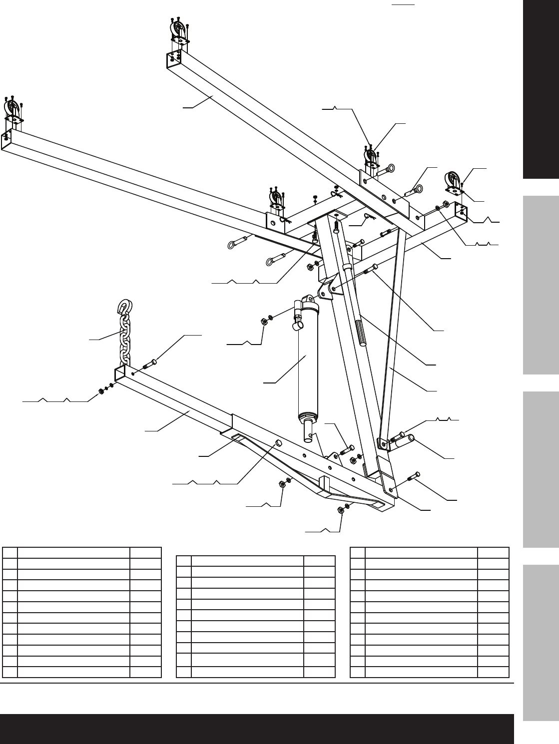
2 1
14
17
2 7
1
3 0
2 8
19
18
7
16
2 0
11
2
2 5
2 9
3 4 5
6
2 6
2 4
2 3
2 2
1093 2
12 13
3 1
1098
13
12
15
12 13
12 13
12 13
16
2 3
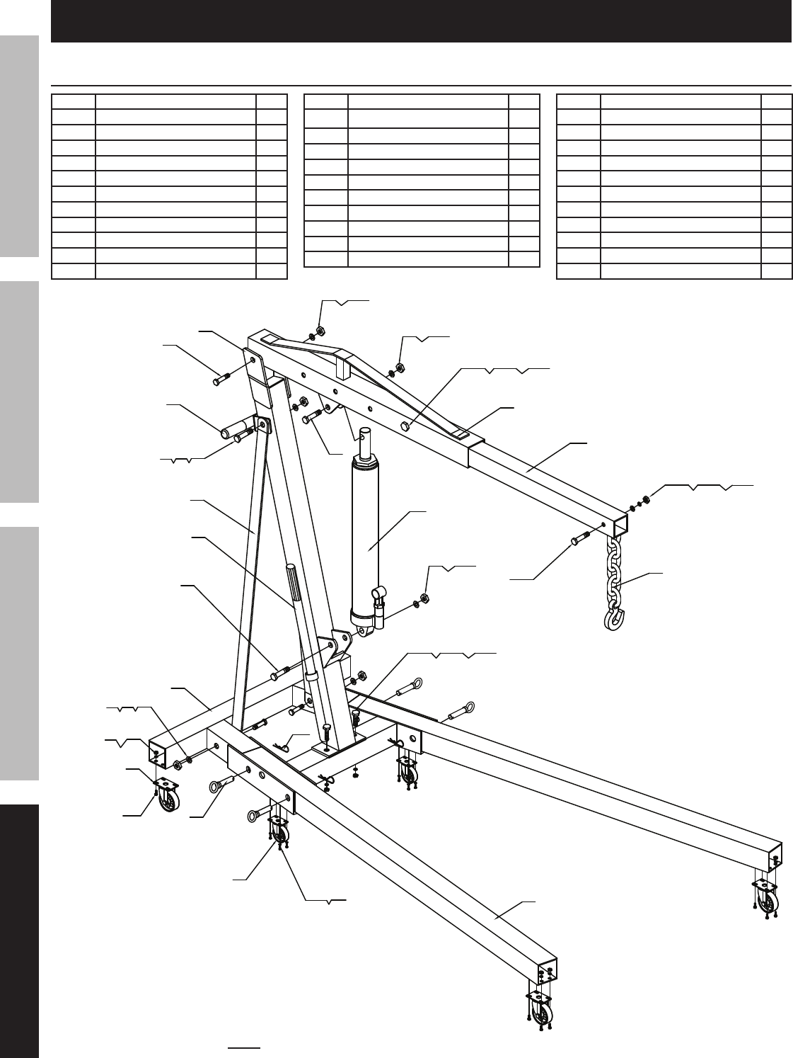
Parts Lists and Diagrams
Crane Parts List and Diagram
Part Description Qty
1 Hook & Chain 1
2 Hex Bolt M12x80 1
3 Lock Washer Ø12 1
4 Flat Washer Ø12 1
5 Hex Nut M12 1
6 Boom Extension 1
7 Boom 1
8 Hex Bolt M14x100 2
9 Flat Washer Ø14 3
10 Hex Nut M14 3
11 Hex Bolt M16x80 1
Part Description Qty
12 Flat Washer Ø16 6
13 Hex Nut M16 6
14 Main Post 1
15 Hex Bolt M16x100 2
16 Hex Bolt M16x110 2
17 Support 2
18 Handle 1
19 8 Ton Long Ram Jack 1
20 Hex Bolt M16x90 1
21 Base 1
Part Description Qty
22 Hex Nut M8 16
23 Lock Washer Ø8 24
24 3½" Swivel Caster 4
25 Hex Bolt M8x20 16
26 Lock Pin 4
27 R Pin 4
28 3" Swivel Caster 2
29 Hex Bolt M8x12 8
30 Leg 2
31 Handrail 1
32 Hex Bolt M14X90 1
Note: Some parts are listed and shown for illustration purposes only,
and are not available individually as replacement parts.
SAFETY OPERATION MAINTENANCESETUP
Page 11For technical questions, please call 1-888-866-5797.Item 69514
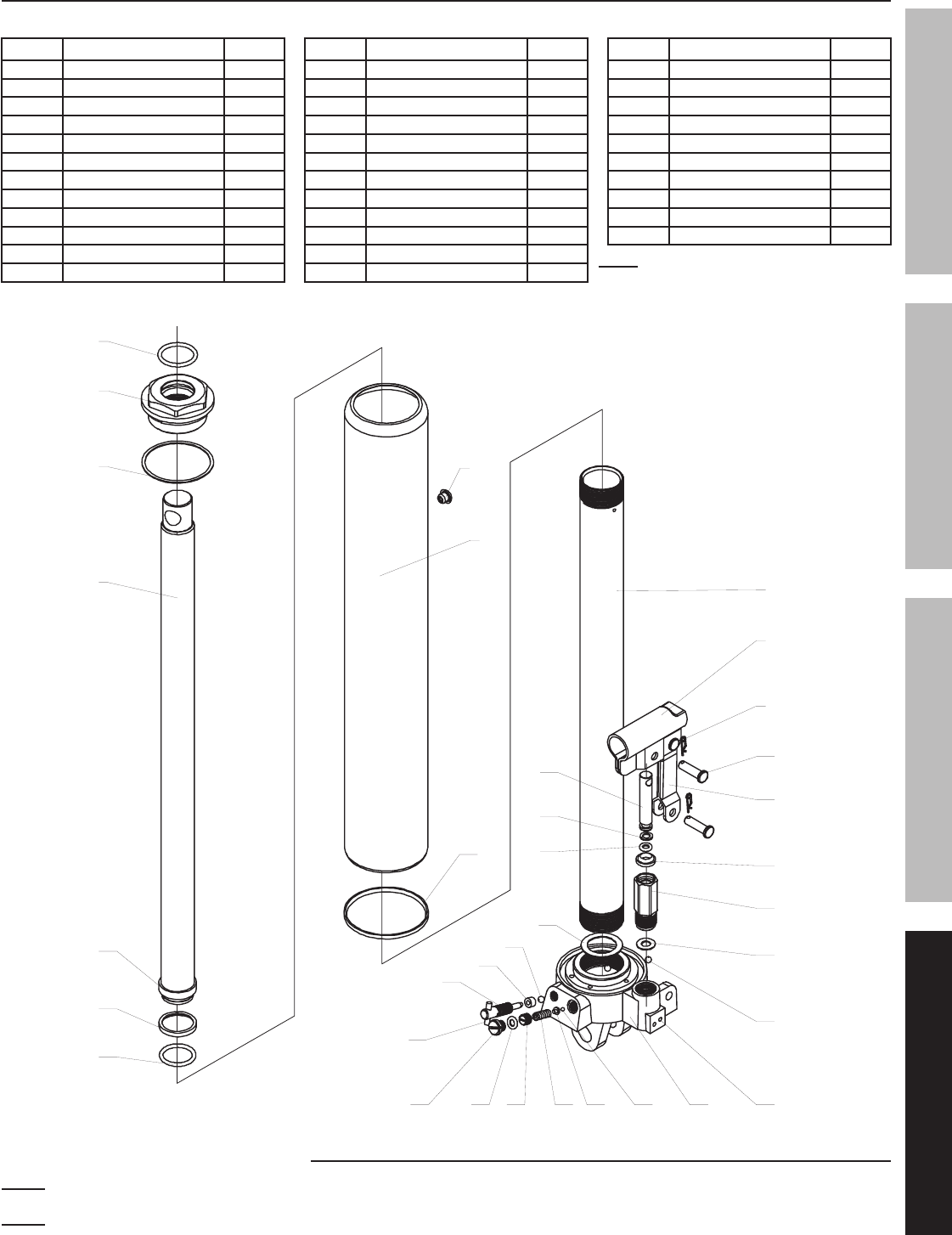
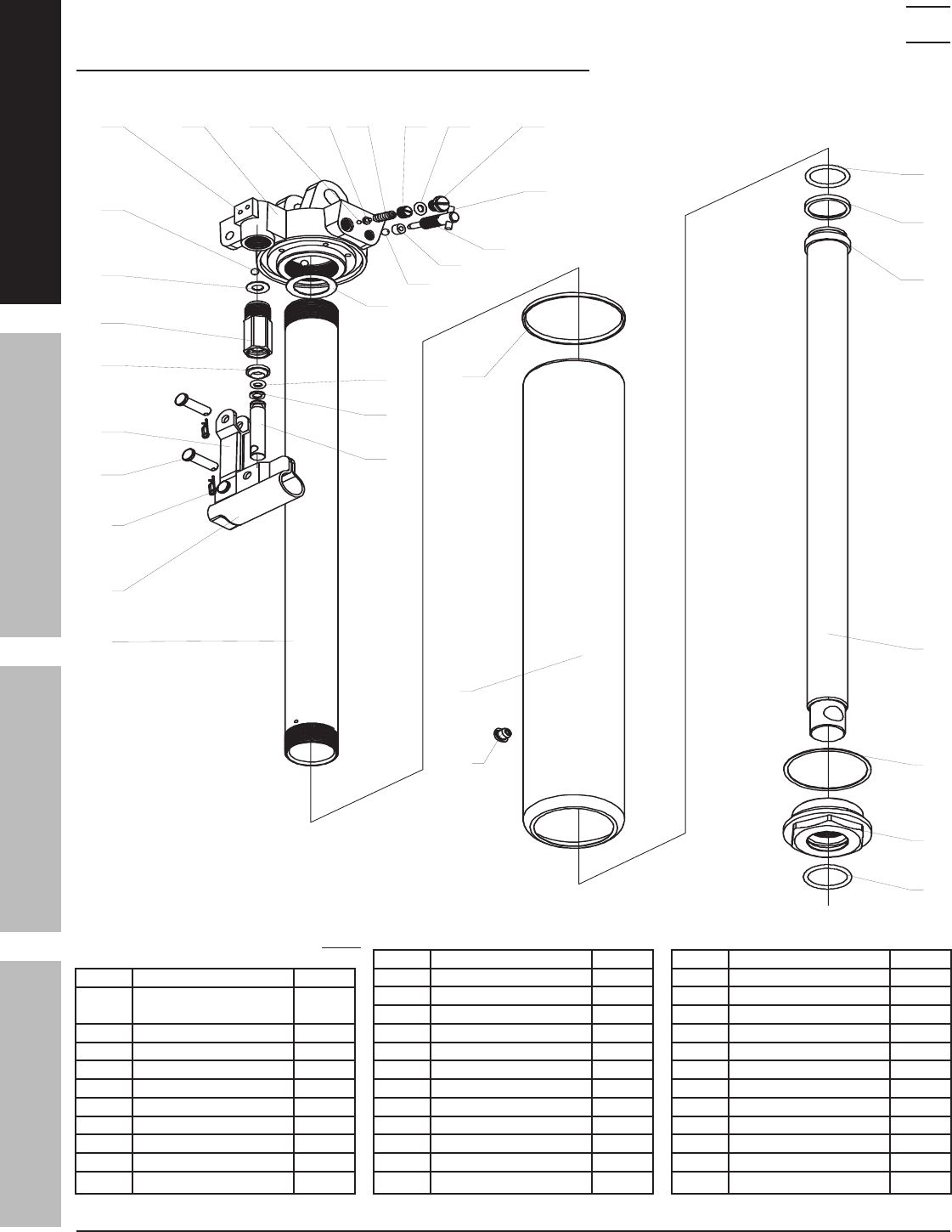
Jack Parts List and Diagram
Part Description Qty
1A Piston Rod 1
2A O-Ring 1
3A Top Cap 1
4A Rectangle Ring 1
5A Cover 1
6A Cylinder 1
7A Piston 1
8A Socket 1
9A Locking Spring 3
10A Axis Pin 2
11A Dust Ring 1
12A Pump Body 1
Part Description Qty
13A Pump Core 1
14A Snap Ring 1
15A O-Ring 1
16A Washer 1
17A Base 1
18A Bolt M5x12 2
19A Trapezoid Ring 1
20A Bowl Ring 1
21A O-Ring 1
22A Piston 1
23A Washer 1
24A Steel Ball Ø4 1
Part Description Qty
25A Spring Base 1
26A Rectangle Ring 1
27A Screw 1
28A Adjustable Screw 1
29A Adjustable Spring 1
30A Linkage 1
31A Steel Ball Ø6 3
32A Rectangle Ring 1
33A Release Valve Rod 1
34A Round Pin 1
Record Product’s Serial Number Here:
Note: If product has no serial number, record month and year of purchase instead.
Note: Some parts are listed and shown for illustration purposes only,
and are not available individually as replacement parts.
3 4
3 3
3 1
3 2
3 1
3 0
2 92 82 7 2 6 2 5 2 4
2 3
1 8
1 6
1 7
1 5
1 4
1 3
1 2
1 1
1 0
9
6
8
2 2
2 1
2 0
1 9
7
5
4
3
2
1
Note: When re-ordering parts from this list,
use the part number with the “A” suffix.
SAFETYOPERATIONMAINTENANCE SETUP

Limited 90 Day Warranty
Harbor Freight Tools Co. makes every effort to assure that its products meet high quality and durability standards,
and warrants to the original purchaser that this product is free from defects in materials and workmanship for the
period of 90 days from the date of purchase. This warranty does not apply to damage due directly or indirectly,
to misuse, abuse, negligence or accidents, repairs or alterations outside our facilities, criminal activity, improper
installation, normal wear and tear, or to lack of maintenance. We shall in no event be liable for death, injuries
to persons or property, or for incidental, contingent, special or consequential damages arising from the use of
our product. Some states do not allow the exclusion or limitation of incidental or consequential damages, so the
above limitation of exclusion may not apply to you. THIS WARRANTY IS EXPRESSLY IN LIEU OF ALL OTHER
WARRANTIES, EXPRESS OR IMPLIED, INCLUDING THE WARRANTIES OF MERCHANTABILITY AND FITNESS.
To take advantage of this warranty, the product or part must be returned to us with transportation charges
prepaid. Proof of purchase date and an explanation of the complaint must accompany the merchandise.
If our inspection verifies the defect, we will either repair or replace the product at our election or we may
elect to refund the purchase price if we cannot readily and quickly provide you with a replacement. We will
return repaired products at our expense, but if we determine there is no defect, or that the defect resulted
from causes not within the scope of our warranty, then you must bear the cost of returning the product.
This warranty gives you specific legal rights and you may also have other rights which vary from state to state.
3491 Mission Oaks Blvd. • PO Box 6009 • Camarillo, CA 93011 • 1-888-866-5797

Garantía limitada de 90 días
Harbor Freight Tools Co. hace todo lo posible para asegurar que sus productos cumplen con altos estándares de
calidad y durabilidad, y garantiza al comprador original que este producto está libre de defectos en sus materiales y
mano de obra durante un plazo de 90 días a partir de la fecha de compra. Esta garantía no corresponde a los daños
resultantes, directa o indirectamente, del mal uso, abuso, negligencia o accidentes, reparaciones o alteraciones
fuera de nuestras instalaciones, actividad delictiva, instalación incorrecta, desgaste normal o falta de mantenimiento.
En ningún caso seremos responsables por muerte, lesiones a personas o bienes, o en el caso de daños incidentales,
contingentes, especiales o consecuentes derivados del uso de nuestro producto. Algunos estados no permiten
la exclusión o limitación de daños incidentales o consecuentes, por lo cual es posible que la anterior limitación
de exclusión no sea aplicable a usted. ESTA GARANTÍA SUSTITUYE EXPRESAMENTE TODAS LAS DEMÁS
GARANTÍAS, EXPRESAS O IMPLÍCITAS, INCLUIDAS LAS GARANTÍAS DE COMERCIABILIDAD Y ADECUACIÓN.
Para obtener los beneficios de esta garantía, deberá remitirnos el producto o pieza con los gastos de transporte
prepagados. Junto con el artículo, deberá remitir, además, el comprobante de la fecha de compra y una
explicación de su reclamo. Si nuestra inspección verifica el defecto, repararemos o sustituiremos el producto,
a nuestra elección, o podemos optar por reintegrar el precio de compra si no podemos fácil y rápidamente
proporcionarle un reemplazo. Los gastos de envío de los productos reparados correrán por nuestra cuenta, pero si
determinamos que no existe ningún defecto, o que el defecto fue resultado de circunstancias que no se encuentran
dentro del alcance de nuestra garantía, usted deberá hacerse cargo de los costos de envío del producto.
Esta garantía le otorga derechos legales específicos y también puede tener otros derechos que varían entre estados.
3491 Mission Oaks Blvd. • PO Box 6009 • Camarillo, CA 93011 • 1-888-866-5797
Artículo 69514
Si desea realizar preguntas técnicas, llame al 1-888-866-5797.
SEGURIDADFUNCIONAMIENTOMANTENIMIENTO CONFIGURACIÓN
Lista de piezas y diagrama del gato
Pieza Descripción
1A Vástago del pistón 1
2A Junta tórica 1
3A Tope superior 1
4A Aro rectángulo 1
5A Cubierta 1
6A Cilindro 1
7A Pistón 1
8A Receptáculo 1
9A Resorte de bloqueo 3
10A Pasador del eje 2
11A Anillo guardapolvo 1
12A Carcasa de la bomba 1
Pieza Descripción
13A Núcleo de la bomba 1
14A Anillo de fijación 1
15A Junta tórica 1
16A Arandela 1
17A Base 1
18A Perno M5x12 2
19A Anillo trapezoidal 1
20A Anillo embudo 1
21A Junta tórica 1
22A Pistón 1
23A Arandela 1
24A Bola de acero Ø4 1
Pieza Descripción
25A Base de resorte 1
26A Aro rectángulo 1
27A de 1
28A Tornillo ajustable 1
29A Resorte ajustable 1
30A Articulación 1
31A Bola de acero Ø6 3
32A Aro rectángulo 1
33A Vástago de la válvula
de descarga
1
34A Pasador circular 1
Anote el número de serie del producto aquí:
Nota: Si el producto no posee número de serie, tome nota del mes y el año de la compra.
Nota: Algunas piezas se detallan y muestran a modo de ilustración únicamente
y no están disponibles por separado como piezas de repuesto.
3 4
3 3
3 1
3 2
3 1
3 0
2 92 82 7 2 6 2 5 2 4
2 3
1 8
1 6
1 7
1 5
1 4
1 3
1 2
1 1
1 0
9
6
8
2 2
2 1
2 0
1 9
7
5
4
3
2
1
Nota: Cuando haga un pedido de esta
lista, utilice el número de pieza con el
sufijo "A".
Página 11
Artículo 69514
Si desea realizar preguntas técnicas, llame al 1-888-866-5797.
SEGURIDAD FUNCIONAMIENTO MANTENIMIENTOCONFIGURACIÓN
2 1
14
17
2 7
1
3 0
2 8
19
18
7
16
2 0
11
2
2 5
2 9
3 4 5
6
2 6
2 4
2 3
2 2
1093 2
12 13
3 1
1098
13
12
15
12 13
12 13
12 13
16
2 3
Listas de piezas y diagramas
Lista de piezas y diagrama de la grúa
Pieza Descripción
1 Gancho y cadena 1
2Perno de cabeza hexagonal M12x80 1
3 Arandela de seguridad Ø12 1
4 Arandela plana Ø12 1
5 Tuerca de cabeza hexagonal M12 1
6 Extensión del brazo 1
7 Brazo 1
8Perno de cabeza hexagonal M14x100 2
9 Arandela plana Ø14 3
10 Tuerca de cabeza hexagonal M14 3
11 Perno de cabeza hexagonal M16x80 1
Pieza Descripción
12 Arandela plana Ø16 6
13 Tuerca de cabeza hexagonal M16 6
14 Poste principal 1
15 Perno de cabeza hexagonal M16x100 2
16 Perno de cabeza hexagonal M16x110 2
17 Soporte 2
18 Manija 1
19 Gato de eje largo de 8 t. 1
20 Perno de cabeza hexagonal M16x90 1
21 Base 1
Pieza Descripción
22 Tuerca de cabeza hexagonal M8 16
23 Arandela de seguridad Ø8 24
24 Rueda giratoria de 3½" 4
25 Perno de cabeza hexagonal M8x20 16
26 Pasador de bloqueo 4
27 Pasador en R 4
28 Rueda giratoria de 3" 2
29 Perno de cabeza hexagonal M8x12 8
30 Pata 2
31 Pasamanos 1
32 Perno de cabeza hexagonal M14x90 1
Nota: Algunas piezas se detallan y muestran a modo de ilustración únicamente
y no están disponibles por separado como piezas de repuesto.
Página 10

Artículo 69514
Si desea realizar preguntas técnicas, llame al 1-888-866-5797.
SEGURIDADFUNCIONAMIENTOMANTENIMIENTO CONFIGURACIÓN
Resolución de problemas
PARA EVITAR LESIONES GRAVES: Tenga cuidado al solucionar un mal
funcionamiento del gato. Manténgase alejado de la carga elevada. Solucione
completamente todos los problemas antes de su uso. Si las soluciones propuestas en la guía "Resolución de
problemas" no solucionan el problema, haga inspeccionar y reparar el gato por un técnico calificado antes de
utilizarlo, Una vez reparado el gato: Pruébelo con cuidado sin carga subiéndolo y bajándolo por completo,
revisando su correcta operación, ANTES DE VOLVER A PONER EL GATO EN FUNCIONAMIENTO.
¡NO UTILICE UN GATO DAÑADO O QUE NO FUNCIONA CORRECTAMENTE!
ADVERTENCIA
POSIBLES SÍNTOMAS
SOLUCIÓN PROBABLE
(Asegúrese de que el gato
no esté sosteniendo una
carga mientras usted intenta
resolver un problema).
El gato no
levanta cargas
correspondientes
a su capacidad
de peso.
La cadena
o el
gancho
se bajan
cuando
están
cargados.
La carrera
de la
bomba
se siente
esponjosa.
La cadena
o el
gancho
no se
levantan al
máximo.
La manija
se mueve
hacia
arriba
cuando el
gato está
cargado.
Pérdida de
aceite del
tapón de
llenado.
X X
Verifique que la válvula de
descarga esté completamente
cerrada.
Purgue el aire del sistema.
X X X
Es posible que las válvulas
estén bloqueadas y no
cierren por completo. Para
limpiar las válvulas:
1. Baje la cadena/el gancho
y cierre firmemente la
válvula de descarga.
2. Levante la cadena/el gancho
manualmente varias pulgadas.
3. Abra la válvula de descarga
y empuje la cadena/el
gancho hacia abajo tan
rápido como sea posible.
XX X
Es posible que el gato tenga poco
aceite. Revise el nivel de aceite
y complete si es necesario.
Es posible que sea necesario
purgar el gato –consulte las
instrucciones en la página 9.
X
Es posible que la unidad tenga
demasiado aceite hidráulico
en su interior, revise el nivel
y ajuste si es necesario.
POR FAVOR, LEA ESTO CON DETENIMIENTO
EL FABRICANTE Y/O DISTRIBUIDOR HA PROPORCIONADO LA LISTA DE PIEZAS Y EL DIAGRAMA DE
MONTAJE QUE SE MUESTRAN EN ESTE MANUAL ÚNICAMENTE COMO HERRAMIENTA DE REFERENCIA.
NI EL FABRICANTE NI EL DISTRIBUIDOR ASEVERAN O GARANTIZAN DE NINGÚN MODO QUE EL/LA
COMPRADOR(A) ESTÉ CALIFICADO(A) PARA REALIZAR REPARACIONES AL PRODUCTO, NI QUE ÉL/ELLA
ESTÉ CALIFICADO(A) PARA REEMPLAZAR NINGUNA PIEZA DEL PRODUCTO. EN REALIDAD, EL FABRICANTE
Y/O EL DISTRIBUIDOR DEJAN EXPRESA CONSTANCIA DE QUE TODAS LAS REPARACIONES Y REEMPLAZOS
DE PIEZAS DEBEN SER EFECTUADOS POR TÉCNICOS DIPLOMADOS Y CERTIFICADOS, Y NO POR EL/
LA COMPRADOR(A). EL/LA COMPRADOR(A) ASUME TODOS LOS RIESGOS Y RESPONSABILIDADES
QUE PUEDAN DERIVARSE DE LAS REPARACIONES DEL PRODUCTO ORIGINAL O DE LAS PIEZAS QUE
REEMPLACE, O QUE PUEDAN DERIVARSE DE LA INSTALACIÓN DE PIEZAS DE REEMPLAZO QUE REALICE.
Página 9

Artículo 69514
Si desea realizar preguntas técnicas, llame al 1-888-866-5797.
SEGURIDAD FUNCIONAMIENTO MANTENIMIENTOCONFIGURACIÓN
Mantenimiento y servicio técnico
Los procedimientos que no se explican
específicamente en este manual deben ser
realizados únicamente por un técnico calificado.
PARA EVITAR LESIONES GRAVES CONSECUENCIA
DE UN FUNCIONAMIENTO ACCIDENTAL:
No utilice el equipo si está dañado. Si detecta ruidos
o vibraciones anormales, corrija el problema antes de su uso.
ADVERTENCIA
Limpieza, mantenimiento y lubricación
1. Antes de cada uso, inspeccione el estado
general del gato. Verifique que no existan partes
rotas, rajadas o dobladas, piezas sueltas o
faltantes o cualquier condición que pueda afectar
el funcionamiento adecuado del producto. Si se
produce algún problema, hágalo corregir antes de
continuar con el uso.
No utilice el equipo si está dañado.
2. Antes de cada uso, pruebe detenidamente
el gato para determinar su funcionamiento
adecuado antes de usarlo. Si el gato parece
no estar funcionando correctamente, siga las
instrucciones para la Purga en la página 9.
3. Cambie el aceite hidráulico al menos
una vez cada tres años:
a. Baje por completo el gato y quite el tapón del
depósito de aceite del lateral de la carcasa.
b. Incline el gato para permitir que el aceite
hidráulico viejo drene por completo de
la carcasa, y al desecharlo cumpla
con las regulaciones locales.
c. Coloque el gato nuevamente en posición
vertical y llene por completo la carcasa
con aceite hidráulico de alta calidad (no
incluido), hasta que el aceite comience
a manar del orificio para carga.
d. Afloje el tornillo de descarga de la válvula y
bombee la manija para purgar el aire del sistema.
e. Vuelva a colocar el tapón del depósito de aceite.
4. Seque con un paño limpio. Luego, almacene el
gato en un lugar seco y seguro, fuera del alcance
de los niños y de otras personas no autorizadas.
Página 8
Artículo 69514
Si desea realizar preguntas técnicas, llame al 1-888-866-5797.
SEGURIDADFUNCIONAMIENTOMANTENIMIENTO CONFIGURACIÓN
Instrucciones para la operación
Antes de instalar o usar este producto, lea la TOTALIDAD DE LA SECCIÓN "INFORMACIÓN
IMPORTANTE SOBRE SEGURIDAD" que se encuentra al comienzo de este manual,
incluyendo todos los textos debajo de los subtítulos.
Nota: Una vez finalizado el ensamblaje, ajuste TODOS los pernos antes de ponerla en funcionamiento por primera vez.
Elevación y descenso
1.
Carga de 3/4 t.
Figura A
Localice el orificio del brazo que tenga un límite
de peso mayor al de la carga que desea izar.
Por ejemplo: Localice en el brazo el orificio
de 1 TON. para cargas que pesen menos
de 1 tonelada. Consulte la Figura 9.
2.
Figura B
Arandela
Tuerca
Perno
Ajuste la extensión del brazo de modo que el orificio
más alejado del extremo del gancho se alinee
con el orificio elegido del brazo. Sujete en el lugar
insertando el perno a través de todos los orificios
alineados y apriete con la arandela y la tuerca.
Consulte la Figura 10 que se muestra arriba.
¡ADVERTENCIA! No se pare debajo del objeto que
está levantando la grúa para motores. Tenga en
cuenta que existe la posibilidad de que una carga
se deslice del gancho y la cadena. Si un elemento
cae de la grúa puede causar lesiones graves.
3. Mueva la grúa de tal modo que el gancho
y la cadena queden directamente por
encima del elemento a izar.
4. Fije firmemente el gancho y la cadena al elemento.
5. Para levantar el brazo, gire por completo la válvula
de descarga del gato en el sentido de las agujas del
reloj (hacia la derecha). Inserte la manija en el gato
y bombee (hacia arriba y hacia abajo) hasta que se
haya elevado el elemento hasta la altura deseada.
¡ADVERTENCIA! Asegúrese de apretar la válvula
de descarga completamente, o el gato puede bajarse
o no ser capaz de llegar a la altura máxima.
¡ADVERTENCIA! NO MUEVA LA GRÚA CUANDO
TIENE CARGA. El diseño de las ruedas no permite
que rueden cuando la grúa está izando objetos pesados.
6. Para bajar la grúa, gire LENTAMENTE la válvula
de descarga del gato en sentido contrario al
de las agujas del reloj (hacia la izquierda).
Cómo plegar el bastidor
¡ADVERTENCIA! No pliegue la grúa mientras
tiene carga.
1. Baje la grúa por completo.
2. Extraiga los pasadores en R de los pasadores
de bloqueo delanteros. Deje colocados
los pasadores de bloqueo traseros.
3. Levante la pata hasta que se apoye contra la manija.
4. Inserte un pasador de bloqueo delantero en
el orificio central de la base, para cada pata,
y vuelva a insertar los pasadores en R.
Instrucciones para la purga
¡IMPORTANTE! Antes del primer uso, verifique
que el nivel de aceite hidráulico sea adecuado
y pruebe detenidamente el equipo. Si no funciona
correctamente, purgue el exceso de aire del
sistema hidráulico de la siguiente manera:
1. Abra la válvula de descarga y baje el gato
completamente.
2. Quite el tapón del depósito de aceite y llene
el depósito con aceite hidráulico (se vende
por separado) hasta el nivel máximo.
3. Aplique presión descendente al brazo y bombee
la manija del gato rápidamente varias veces.
4. Revise el orificio para carga de aceite
y, de ser necesario, llene hasta arriba
el orificio con aceite hidráulico.
5. Vuelva a colocar el tapón del depósito de
aceite y cierre la válvula de descarga.
6. Pruebe el equipo varias veces para determinar
su correcto funcionamiento antes de intentar
levantar una carga. Si, después de la purga,
el equipo todavía no parece estar funcionando
correctamente, no lo utilice hasta que un técnico
de servicio calificado lo haya reparado.
.
.
.
.
.
.
.
.
Página 7
Artículo 69514
Si desea realizar preguntas técnicas, llame al 1-888-866-5797.
SEGURIDAD FUNCIONAMIENTO MANTENIMIENTOCONFIGURACIÓN
5.
Figura H
Arandela
Arandela
Tuerca
Tuerca
Gato
Perno (20)
Perno (11)
Utilice un perno, una arandela y una tuerca
para sujetar el extremo inferior del gato al poste,
y otro perno, otra arandela y otra tuerca para
sujetar la parte superior del gato al brazo.
6.
Figura I
Arandela
Arandela
Tuerca
Tuerca
Extensión
del brazo
Perno (2)
Perno (32)
Deslice la extensión del brazo adentro del brazo
y utilice el perno, la arandela y la tuerca para fijar
en el índice de carga deseado. Utilice el perno,
la arandela y la tuerca para sujetar el gancho y
la cadena al extremo de la extensión del brazo.
Figura J: Grúa para motores ensamblada
Página 6
Artículo 69514
Si desea realizar preguntas técnicas, llame al 1-888-866-5797.
SEGURIDADFUNCIONAMIENTOMANTENIMIENTO CONFIGURACIÓN
1.
2 5
2 4
2 3
2 2
3 0
2 1 2 6
2 7
2 8 2 92 3
Figura C
(Ensamblado)
Deslice las patas dentro de la parte delantera de
la base y bloquéelas en su lugar utilizando los
pasadores de bloqueo. Para insertar los pasadores
de bloqueo, levante el frente de la base hasta lograr
la alineación de los orificios. Después de colocar los
cuatro pasadores de bloqueo, inserte un pasador
en R a través del pequeño agujero en el extremo
de cada collarín hasta que encaje en su lugar.
Nota: Asegúrese de que los pasadores de bloqueo
estén bien sujetos antes de continuar.
2.
Base Assembly
9 10
8
(Ensamblado)
Figura D
Utilice los pernos, arandelas y tuercas para fijar
la parte inferior del poste a la base.
3.
Figura E
Arandela
Arandelas
Tuerca
Tuerca
Poste
Soporte
Perno (15)
Perno (15)
Perno (16)
Las curvas de
los soportes se
proyectan hacia
afuera en la parte
superior y en la
parte inferior, como
se muestra arriba.
Soporte
Poste
Pata Pata
Soporte
Utilice dos pernos, dos arandelas y dos tuercas para
sujetar los extremos inferiores de los soportes a la
parte interna del bastidor; luego, utilice un perno,
una arandela y una tuerca para sujetar los extremos
superiores de los soportes y la manija al poste.
Manija
Poste
Soporte
Soporte
(no se muestra)
Figura F
Nota: Deslice la manija entre los soportes y el poste;
alinee todos los orificios y luego asegure en su lugar.
4.
Figura G
Arandela
Brazo
Tuerca
Perno (16)
Utilice el perno, la arandela y la tuerca para
sujetar el brazo a la parte superior del poste.
Página 5

Artículo 69514
Si desea realizar preguntas técnicas, llame al 1-888-866-5797.
SEGURIDAD FUNCIONAMIENTO MANTENIMIENTOCONFIGURACIÓN
Especificaciones
Especificaciones
Capacidad
del gato 8 t.
Posiciones del brazo
2 t. 84 pulg.
1-1/2 t. 89 pulg.
1 t. 95 pulg.
1/2 t. 100 pulg.
Cumple con los estándares ANSI/ASME PALD 2005
Montaje
Pieza
N° 32
14x90
mm
Pieza
N° 8
14x100
mm
Pieza
N° 11
16x80
mm
Pieza
N° 20
16x90
mm
Pieza
N° 15
16x100
mm
Pieza
N° 16
16x110
mm
Pieza
N° 2
12x80
mm
Pieza
N° 25
8x20
mm
Pieza
N° 29
8x12
mm
PARA EVITAR LESIONES GRAVES Y LA MUERTE: Durante el montaje deben utilizarse
los pernos correctos. Para asegurarse de utilizar los pernos correctos en el lugar correcto, compare
cuidadosamente los pernos con los de la "Ilustración para la identificación de pernos" que se ve arriba, y
con las medidas que se muestran en la lista de piezas y en los diagramas de montaje que encontrará en la
última parte de este manual.
¡ADVERTENCIA! Para mayor seguridad y un fácil montaje, utilice
dos personas para montar la grúa para taller.
¡PRECAUCIÓN! NO APRIETE LOS PERNOS HASTA QUE HAYA TERMINADO COMPLETAMENTE
CON EL MONTAJE.
DE LO CONTRARIO, LAS PIEZAS NO SE ALINEARÁN ADECUADAMENTE.
ADVERTENCIA
Página 4

Artículo 69514
Si desea realizar preguntas técnicas, llame al 1-888-866-5797.
SEGURIDADFUNCIONAMIENTOMANTENIMIENTO CONFIGURACIÓN
11. Verifique que el gato de repuesto tenga la
misma capacidad nominal, los mismos lugares
de montaje y la misma longitud máxima.
12. No apta para usos aeronáuticos.
13. Inspeccione la grúa antes de cada uso; no la
utilice si hay piezas sueltas o dañadas.
14. Mantenga el área de trabajo limpia y
bien iluminada. Los lugares de trabajo
desordenados facilitan los accidentes.
15. Mantenga alejados a los curiosos, los niños y los
visitantes mientras opere la grúa para motores. Las
distracciones pueden hacer que pierda el control.
16. Manténgase alerta. Preste atención a lo que está
haciendo, y utilice el sentido común al operar un
gato. Cuando esté cansado o bajo la influencia de
drogas, alcohol o medicamentos, no utilice el gato.
Un momento de distracción mientras opera un
gato puede generar lesiones personales graves.
17. Siga las instrucciones de la sección "Inspección,
mantenimiento y limpieza" de este manual.
El uso de piezas no autorizadas o no
seguir las instrucciones de mantenimiento
puede provocar riesgo de lesiones y puede
invalidar las garantías aplicables.
18. Conserve las etiquetas y placas de la grúa para
motores. Estas tienen información importante.
Si faltan o son ilegibles, póngase en contacto con
Harbor Freight Tools para solicitar un reemplazo.
19. Antes de utilizarlo, lea el manual de instrucciones
del fabricante del objeto que va a levantar.
20. Los usos industriales deben cumplir con los
requisitos de la Administración de Seguridad
y Salud Ocupacional (OSHA).
21. Las advertencias, precauciones e instrucciones
que se describen en este manual no pueden
cubrir todas las condiciones y situaciones
posibles que puedan ocurrir. El usuario debe
entender que el sentido común y la prudencia
son factores que no pueden integrarse a este
producto, sino que el operador debe proveerlos.
CONSERVE ESTAS INSTRUCCIONES.
Página 3
Artículo 69514
Si desea realizar preguntas técnicas, llame al 1-888-866-5797.
SEGURIDAD FUNCIONAMIENTO MANTENIMIENTOCONFIGURACIÓN
Contenido
Seguridad ................................................... 2
Especificaciones ......................................... 4
Instalación .................................................. 4
Funcionamiento .......................................... 7
Mantenimiento ............................................ 8
Listas de piezas y diagramas ................... 10
Garantía..................................................... 12
SÍMBOLOS DE ADVERTENCIA Y DEFINICIONES
Este es el símbolo de alerta de seguridad. Se utiliza para alertarlo sobre potenciales
riesgos de sufrir lesiones personales. Para evitar posibles lesiones o la muerte,
acate todos los mensajes de seguridad que acompañan a esta señal.
PELIGRO
Indica una situación peligrosa que, de no evitarse,
provocará la muerte o lesiones graves.
ADVERTENCIA
Indica una situación peligrosa que, de no evitarse,
podría provocar la muerte o lesiones graves.
PRECAUCIÓN
Indica una situación peligrosa que, de no evitarse,
podría provocar lesiones menores o de moderada gravedad.
PRECAUCIÓN
AVISO
Hace referencia a prácticas no relacionadas con lesiones personales.
INFORMACIÓN IMPORTANTE SOBRE SEGURIDAD
Advertencias de seguridad generales
ADVERTENCIA
Lea todas las advertencias e instrucciones de seguridad.
No seguir las advertencias e instrucciones puede ocasionar lesiones graves.
Conserve todas las advertencias e instrucciones para referencia futura.
1. Estudie, comprenda y siga todas las
instrucciones antes de utilizar este dispositivo.
2. No exceda la capacidad nominal
de 2 toneladas de la grúa para motores.
3. Úsela solo en superficies duras y niveladas.
4. Antes de trasladarla, baje la carga hasta
el punto más bajo posible.
5. Utilice únicamente eslingas o cadenas cuya
capacidad nominal sea mayor al peso de
la carga que está siendo levantada.
6. No permita que la carga se balancee o caiga
violentamente mientras se está bajando o moviendo.
7. No realice alteraciones o modificaciones en la grúa
para motores. No ajuste la válvula de seguridad.
8. Extienda correctamente las prolongaciones
de las patas y asegure el brazo en un entorno
adecuado antes de su uso.
9. Siga las indicaciones de capacidad marcadas
en el brazo; la capacidad disminuye a medida
que el brazo se alarga.
10. Durante el uso, utilice gafas de seguridad
y guantes de trabajo de caucho de alta
resistencia aprobados por el ANSI .
Página 2