Harbor Freight 42709 Owner S Manual
2014-07-05
: Harbor-Freight Harbor-Freight-42709-Owner-S-Manual harbor-freight-42709-owner-s-manual harbor-freight pdf
Open the PDF directly: View PDF ![]() .
.
Page Count: 24
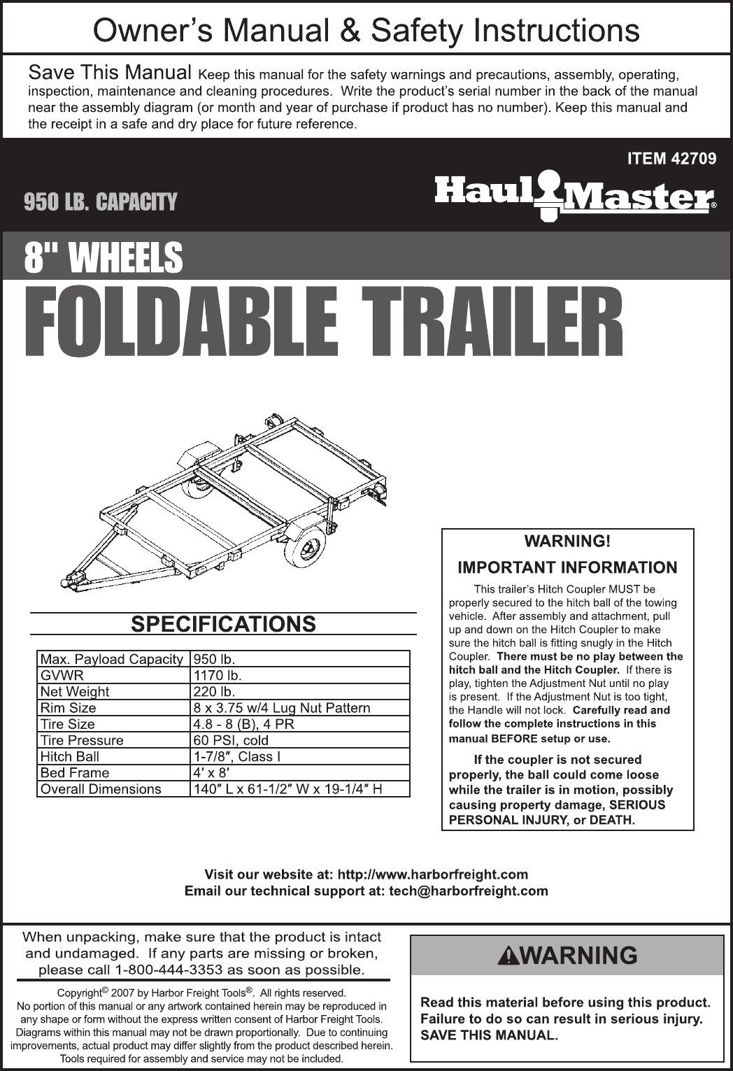

Page 2 For technical questions, please call 1-800-444-3353. Item 42709
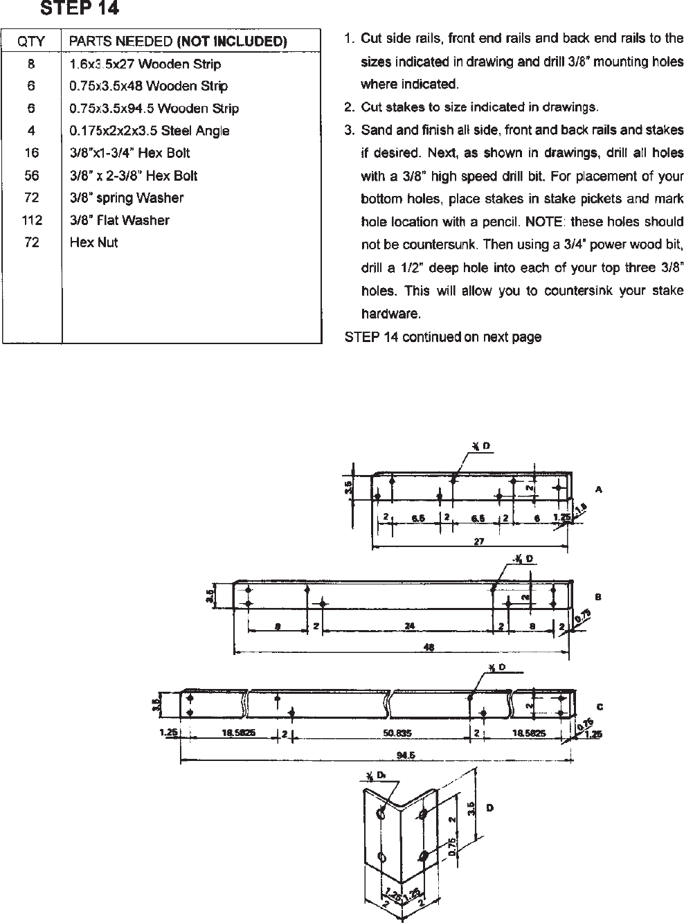
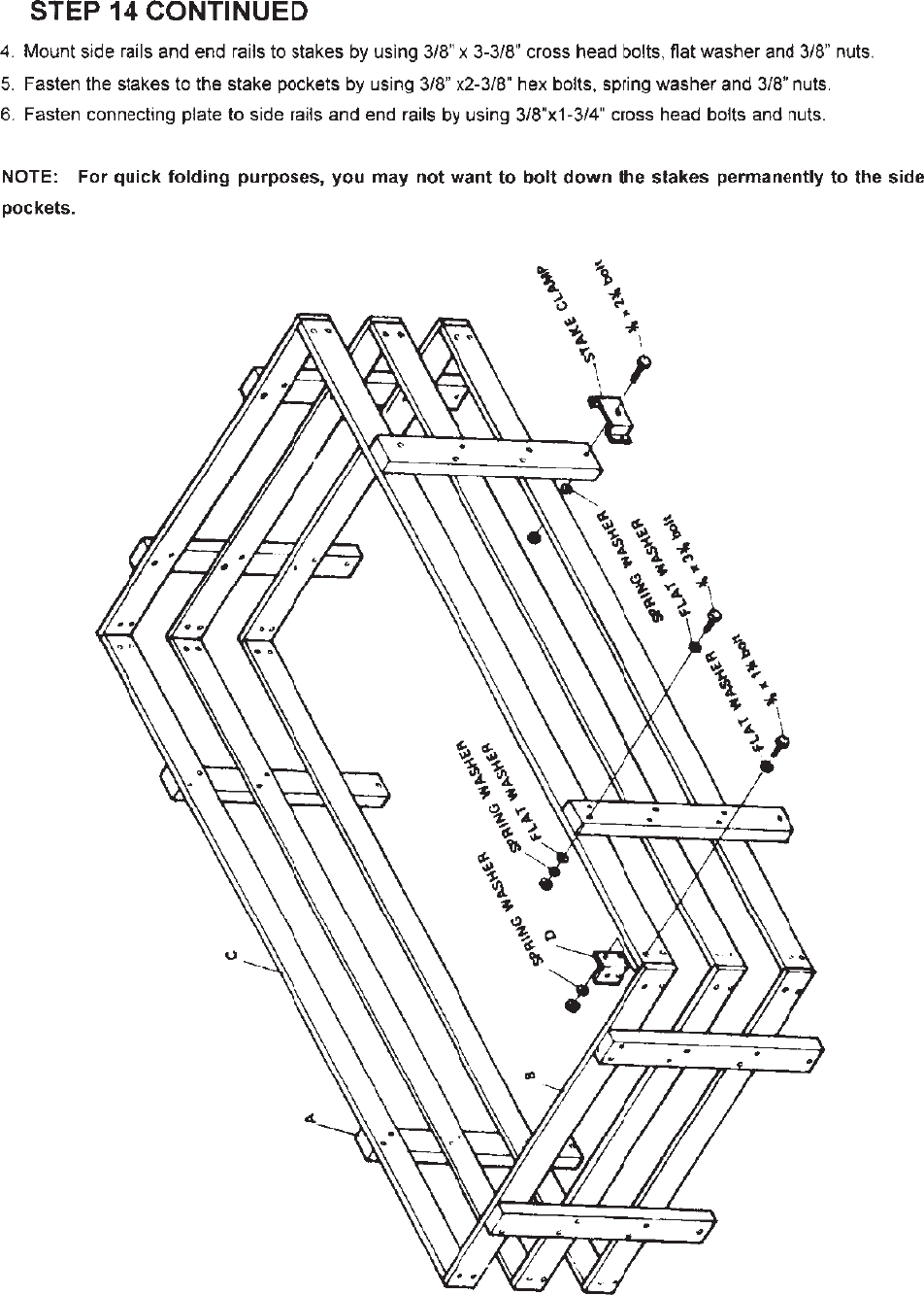
PARTS LIST
PART DESCRIPTION QTY
1FL Front Left Side Rail 1
1FR Front Right Side Rail 1
1RL Rear Left Side Rail 1
1RR Rear Right Side Rail 1
2A Cross Member 1
2B Cross Member 5
3L Left Connecting Rail 1
3R Right Connecting Rail 1
4Spare Tire Bar 1
5 “T” Plate 1
6 Coupler Base 1
7 Coupler 1
8 Safety Chain 1
9 “L”Latch 2
10 Rotation Plate (Flat) 2
11L Left Rotation Plate 1
11R Right Rotation Plate 1
12L Spring Hanger 1
12R Spring Hanger 1
13 Caster 4
14 Spring Plate 2
15 Spring 2
16 Axle 1
17 V-Bolt 4
18 Hub 2
19 Tire/Rim Assembly 2
20 Bearing 2
21 Dust Cap 2
22 Fender 2
23 Fender Seat 2
24 Side Running Light 2
25 Stake Clamp 8
26 Tail Light Bracket 2
27 License Plate Bracket 1
28L Left Tail Light 1
28R Right Tail Light 1
29 Safety Pin 1
30L Caster Base (Left) 1
30R Caster Base (Right) 1
31 Grease Fitting 2
32 Seal 2
PART DESCRIPTION QTY
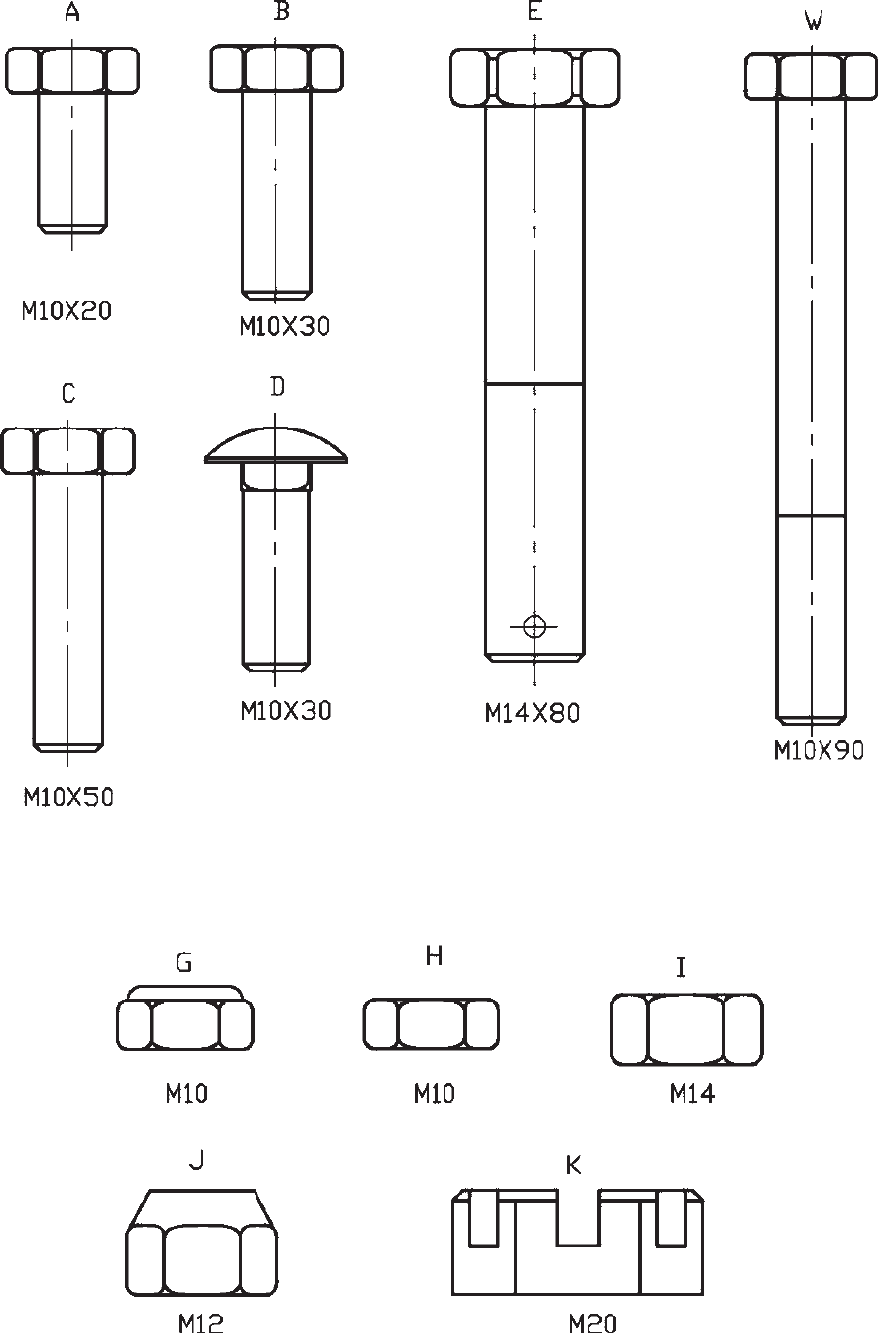
A M10X20 Bolt 64
B M10X30 Bolt 14
C M10X50 Bolt 1
D M10X30 Carriage Bolt 4
E M14X80 Bolt 6
G M10 Nylon Nut 92
H M10 Hex Nut 1
I M14 Hex Nut 6
J M12 Lug Nut 8
K M20 Castle Nut 2
L10 Spring Washer 8
N20 Flat Washer 2
O 4 Cotter Pin 2
P 3 Cotter Pin 6
Q 3mm “R” Pin 2
R 4mm Self Tapping Screw 4
S 2mm “R” Pin 1
W M10X90 Bolt 2
Page 3For technical questions, please call 1-800-444-3353.Item 42709
Page 4 For technical questions, please call 1-800-444-3353. Item 42709
Page 5For technical questions, please call 1-800-444-3353.Item 42709
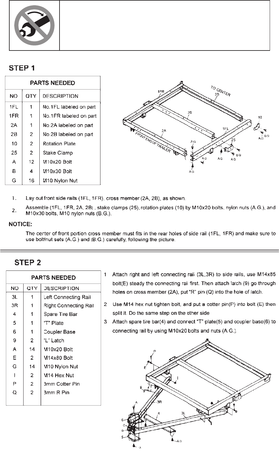
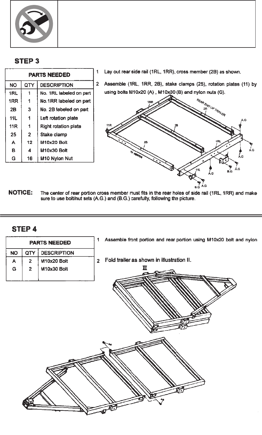
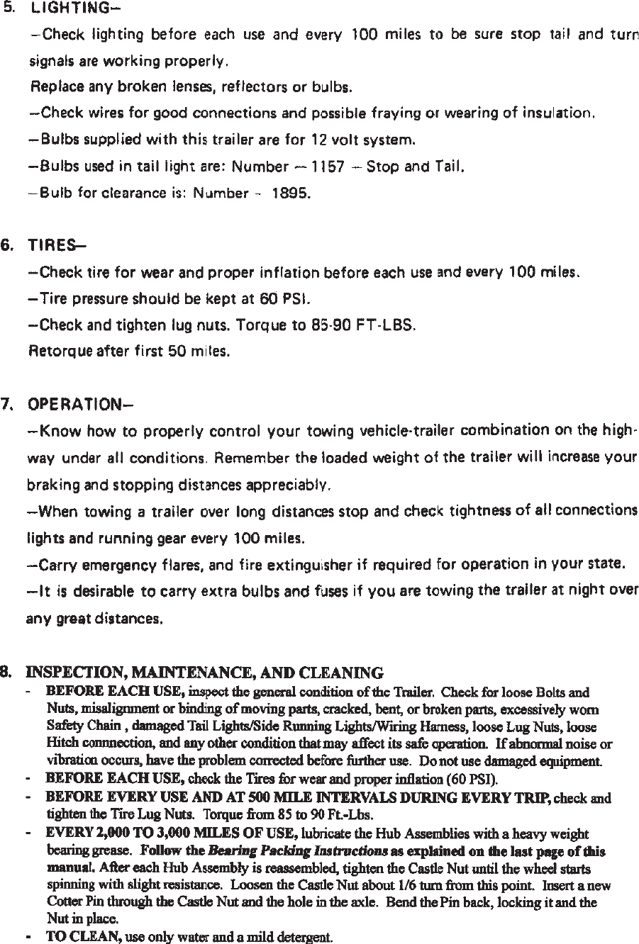
DON’T TIGHTEN YET!
TO MAKE ASSEMBLY EASIER, wait until assembly is
complete and all hardware is in place before tightening
any nut or bolt. Leave hardware snug until then.
Page 6 For technical questions, please call 1-800-444-3353. Item 42709
DON’T TIGHTEN YET!
TO MAKE ASSEMBLY EASIER, wait until assembly is
complete and all hardware is in place before tightening
any nut or bolt. Leave hardware snug until then.
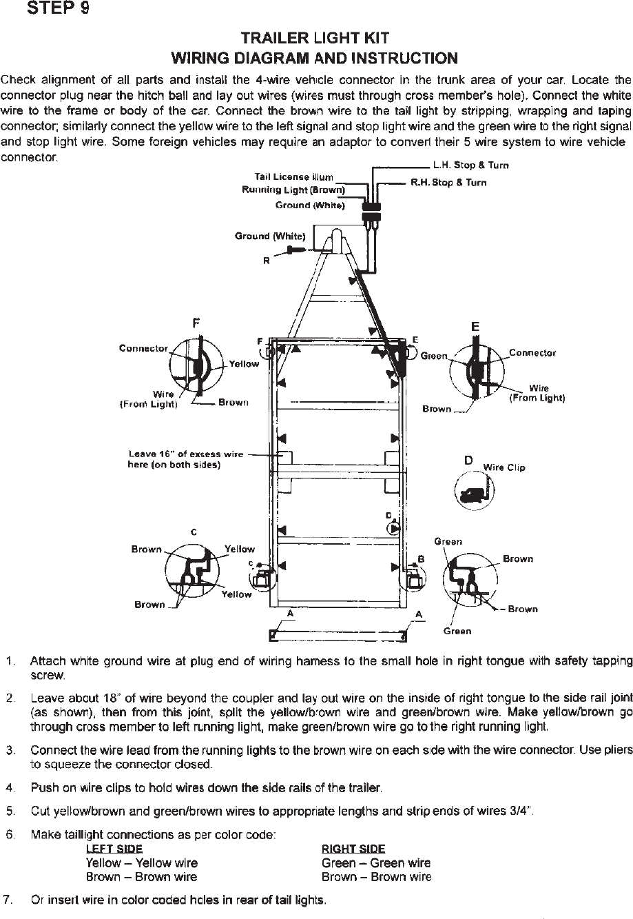
nut as diagram shows. Do not overtighten the nuts to allow trailer
to fold easily.
Page 7For technical questions, please call 1-800-444-3353.Item 42709
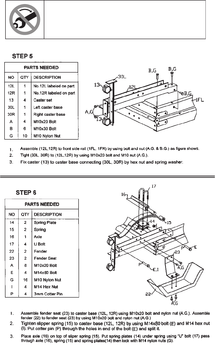
DON’T TIGHTEN YET!
TO MAKE ASSEMBLY EASIER, wait until assembly is
complete and all hardware is in place before tightening
any nut or bolt. Leave hardware snug until then.
Page 8 For technical questions, please call 1-800-444-3353. Item 42709
DON’T TIGHTEN YET!
TO MAKE ASSEMBLY EASIER, wait until assembly is
complete and all hardware is in place before tightening
any nut or bolt. Leave hardware snug until then.
Page 9For technical questions, please call 1-800-444-3353.Item 42709
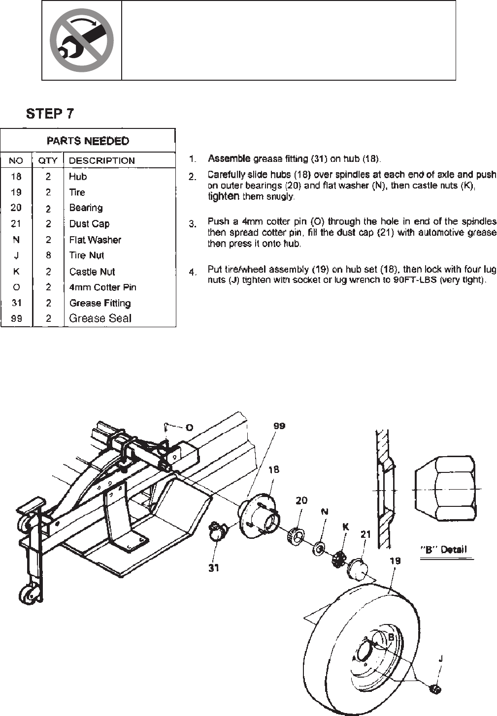
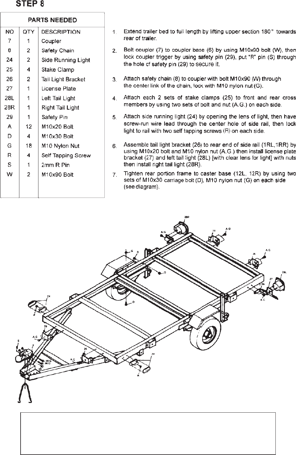
TIGHTEN ALL HARDWARE!
Now that frame is completely assembled, retrace all assembly steps
and make sure that all hardware is properly wrench-tightened.
Also, tighten lug nuts/lug bolts to 90 ft-lb.
Page 10 For technical questions, please call 1-800-444-3353. Item 42709
Page 11For technical questions, please call 1-800-444-3353.Item 42709
Note: Casters are designed to allow
repositioning of the trailer only.
Do not roll the trailer long
distances on casters.
Page 12 For technical questions, please call 1-800-444-3353. Item 42709
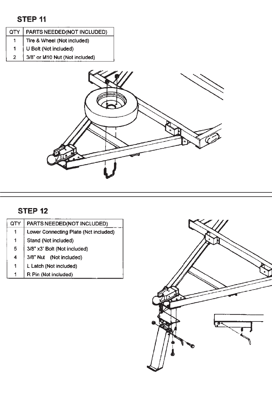
Use U-bolt under bar and through two holes in the rim.
Secure with nuts, tightening them evenly.
Make sure the spare tire is held rmly in place.
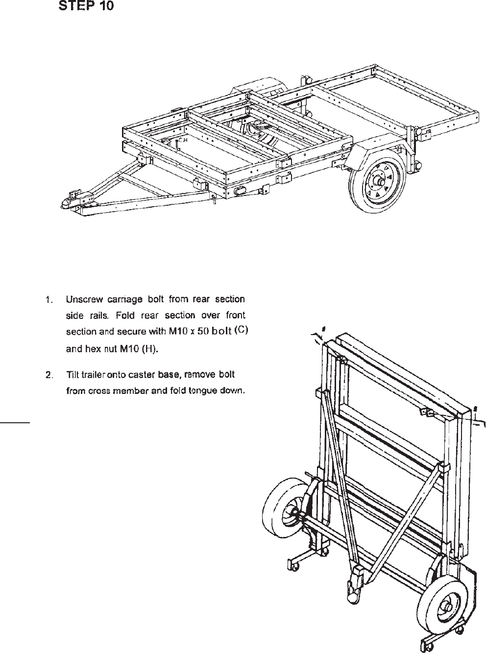
1. Assemble the stand as shown.
2. Remove R-pin, pivot stand into transport
position, and replace R-pin.
Page 13For technical questions, please call 1-800-444-3353.Item 42709
Page 14 For technical questions, please call 1-800-444-3353. Item 42709
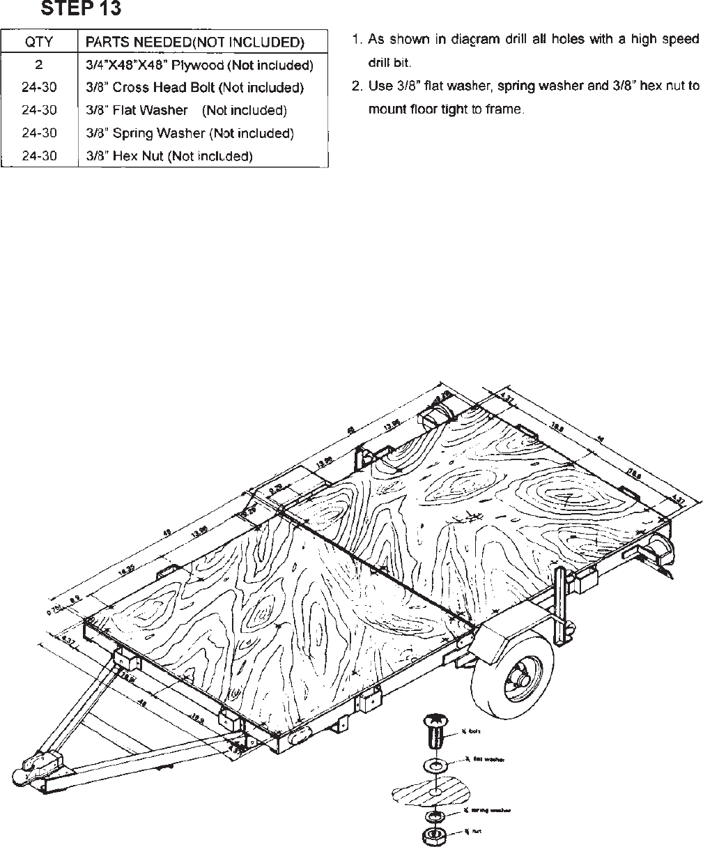
.
Page 15For technical questions, please call 1-800-444-3353.Item 42709
Page 16 For technical questions, please call 1-800-444-3353. Item 42709
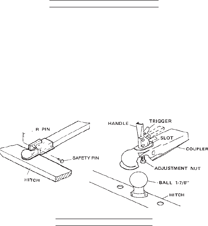
SPECIAL NOTICE FOR COUPLER
1. Only use a 1-7/8" ball hitch (not included) on the towing vehicle.
2. Temporarily remove the "R" Pin and Safety Pin. Then, pull up on the Trigger and lift up on the Handle.
3. NOTE: To reduce friction between the hitch ball and Coupler, apply a layer of heavyweight grease over
the hitch ball.
4. With assistance, place the Coupler over the vehicle's hitch ball and pull back on the Trigger and push
down on the Handle until the Trigger locks in the slot. Pull up and down on the Coupler to make sure the
hitch ball is tting snugly in the Coupler. There should be no play between the hitch ball and Coupler.
IMPORTANT - If there is play, tighten the Adjustment Nut until no play is present:
After unlocking the Handle, the Nut retaining plate (holding the adjusting nut in place) needs to be
pressed back while the Nut is tightened. After Nut is tightened, the retaining plate needs to t in place
against the ats of the Nut to prevent it from moving. This adjustment should be done by 2 people. If the
Adjustment Nut is too tight, the Handle will not lock.
After the Adjustment Nut is properly adjusted, pull back on the Trigger and push down on the Handle until
the Trigger locks in the slot. Pull up on Handle rmly to make sure the Trigger is locked in place and the
Handle cannot move. Replace the Safety Pin and "R" Pin.
TRAILER LICENSING NOTICE
Some states may consider that this trailer kit is a specially constructed or homemade vehicle for registration
licensing and/or titling purposes. The M.C.O. (Manufacturer's Certicate of Origin) supplied with your trailer
should be lled out and signed by the dealer transferring ownership to you. When licensing your trailer, you
will need the signed M.C.O., a purchase invoice, cash register receipt, or bill of sale showing the purchase
and retail sales tax or use tax collection by the retailer. Take these to your local Department of Motor Vehicle
and upon payment of the appropriate State fees, you will be issued a title, registration and license plate (if
required). Some states will require inspection of the assembled and nished trailer kit before issuing a title
registration/license. If you require additional information or guidance on licensing or titling, please consult
your State Department of Motor Vehicles.
Page 17For technical questions, please call 1-800-444-3353.Item 42709
950 lb.
95 lb.
Page 18 For technical questions, please call 1-800-444-3353. Item 42709
Page 19For technical questions, please call 1-800-444-3353.Item 42709
TIRE INFORMATION
Tire Terminology Glossary
• Accessory weight means- the combined weight of
automatic transmission, power steering, power brakes, power
windows, power seats, radio, and heater, to the extent that
these items are available as factory-installed equipment.
• Carcass means- the tire structure except for the tread which
provides the major portion of the tire’s capability to deect in
response to the vertical loads and tractive forces that the tire
transmits from the roadway to the non-pneumatic rim, the
wheel center member, or the vehicle and which attaches to
the vehicle or attaches, either integrally or separably, to the
wheel center member or non-pneumatic rim.
• Carcass separation means- the pulling away of the carcass
from the non-pneumatic rim or wheel center member.
• Chunking means- the breaking away of pieces of the
carcass or tread.
• Cracking means- any parting within the carcass, tread, or
any components that connect the tire to the wheel center
member.
• Curb weight means- the weight of a motor vehicle with
standard equipment including the maximum capacity of fuel,
oil, and coolant, and, if so equipped, air conditioning and
additional weight optional engine.
• Load rating means- the maximum load a tire is rated to carry.
• Maximum loaded vehicle weight means- the sum of:
a. Curb weight;
b. Accessory weight;
c. Vehicle capacity weight; and
d. Production options weight.
• Maximum tire width means- the greater of either the linear
distance between the exterior edges of the carcass or the linear
distance between the exterior edges of the tread, both being
measured parallel to the rolling axis of the tire.
• Normal occupant weight means- 68 kilograms times the
number of occupants.
• Occupant distribution means- distribution of occupants in
a vehicle.
• Production options weight means- the combined weight
of those installed regular production options weighing over
2.3 kilograms in excess of those standard items which
they replace, not previously considered in curb weight or
accessory weight, including heavy duty brakes, ride levelers,
roof rack, heavy duty battery, and special trim.
• Tread means- that portion of the tire that comes in contact
with the road.
• Tread separation means- pulling away of the tread from the
carcass.
• Vehicle capacity weight means- the rated cargo and
luggage load plus 68 kilograms times the vehicle’s
designated seating capacity.
• Vehicle maximum load on the tire means- that load on an
individual tire that is determined by distributing to each axle
its share of the maximum loaded vehicle weight and dividing
by two.
• Vehicle normal load on the tire means- that load on an
individual tire that is determined by distributing to each axle
its share of the curb weight, accessory weight, and normal
occupant weight and dividing by 2.
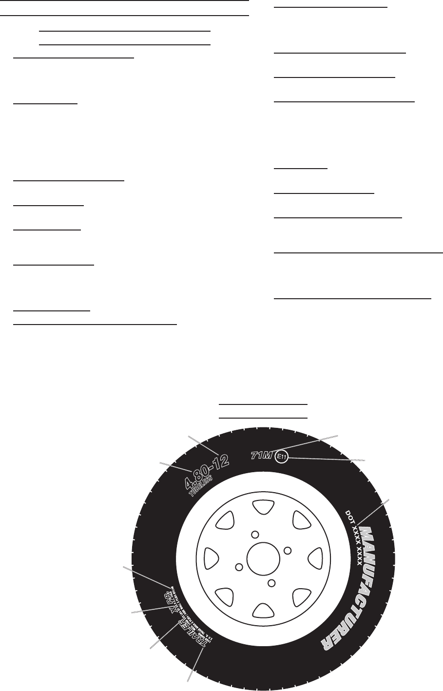
Tire Markings
Load index and
Speed rating*
European tire
certicate*
U.S. DOT tire
identication
number
*Information not required by U.S. DOT
Inner diameter
in inches
Section width
in inches
Trailer
tire
Maximum
load rating
Tire ply
composition
and materials
used
Maximum
permissible
ination
pressure
REV 07f, 09b, 09g
Page 20 For technical questions, please call 1-800-444-3353. Item 42709
• Section width- This number gives the width of the tire in
inches. The larger the number, the wider the tire. (The
markings on the example tire diagram show 4.80. The
markings on your tire may differ.)
• Inner diameter- This number gives the inner diameter of
the tire in inches. This is also the rim diameter in inches.
(The markings on the example tire diagram show 12. The
markings on your tire may differ.)
• U.S. DOT tire identication number- This begins with the
letters “DOT” and indicates that the tire meets all federal
standards. The next two numbers or letters are the plant
code where it was manufactured, and the last four numbers
represent the week and year that the tire was built. For
example, the numbers 2107 mean the 21st week of 2007.
Any other numbers used are marketing codes used at
the manufacturer’s discretion. This information is used to
contact consumers if a tire defect requires a recall.
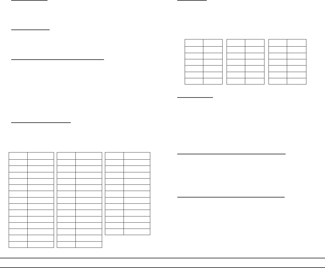
• Maximum Load Rating- This number indicates the
maximum load in kilograms and pounds that can be carried
by the tire.
Code Pounds
71 761
72 783
73 805
74 827
75 853
76 882
77 908
78 937
79 963
80 992
81 1,019
82 1,047
83 1,074
84 1,102
Code Pounds
85 1,135
86 1,168
87 1,201
88 1,235
89 1,279
90 1,323
91 1,356
92 1,389
93 1,433
94 1,477
95 1,521
96 1,565
97 1,609
98 1,653
Code Pounds
99 1,709
100 1,764
101 1,819
102 1,874
103 1,929
104 1,984
105 2,039
106 2,094
107 2,149
108 2,205
109 2,271
110 2,337
Load Index Rating Codes
• Load index- This is a measurement of how much weight
each tire can support. See chart above. (The markings on
the example tire diagram show 71. The markings on your
tire may differ.) Note: You may not nd this information on
all tires because it is not required by law.
•
Code MPH
F 50
G 56
J 62
K 68
L 75
M 81
Code MPH
N 87
P 94
Q 100
R 106
S112
T118
Code MPH
U 124
H 130
V 149
Z 149
W 168
Y 186
Tire Speed Rating Codes
Speed Rating- The speed rating denotes the speed at
which a tire is designed to be driven for extended periods of
time. This does not indicate that the vehicle or rims can
safely reach or maintain that speed. These ratings are
listed to the right. (The markings on the example tire
diagram show M. The markings on your tire may differ.)
Note: You may not nd this information on all tires because
it is not required by law.
• Tire Ply Composition and Materials Used- The number
of plies indicates the number of layers of rubber-coated
fabric in the tire. In general, the greater the number of plies,
the more weight a tire can support. Tire manufacturers also
must indicate the materials in the tire, which include steel,
nylon, polyester, and others.
• Maximum Permissible Ination Pressure- This number is
the greatest amount of air pressure that should ever be put
in the tire under normal driving conditions.
BEARING PACKING INSTRUCTIONS
Important
Read and adhere to the following instructions; failure to read and obey all
of the following instructions COMPLETELY will void the warranty and can result
in damage to the trailer, property damage, or SERIOUS PERSONAL INJURY.
Whenever a hub is disassembled (if a hub on a new unit requires assembly or a hub is
disassembled for maintenance), the following procedure MUST be followed.
1. Using a suitable solvent, thoroughly clean
the bearings and the rest of the parts in
the Hub assembly of all grease, dirt, metal
shavings, or any other foreign object. The
parts must be cleaned even if they are
new or clean.
2. Allow all pieces to dry completely.
3. Make sure that your hands are thoroughly
clean and the bearing packer (not included)
is also thoroughly clean.
4. Place fresh, clean bearing grease in the
packer.
5. With the grease-lled bearing packer in one
hand and the bearing in the other, press the
bearing into the grease, forcing the grease
inside the slots in the bearing, continue
doing this until every slot in the bearing is
completely full of grease.
6. Finish assembling the hub/wheel assembly
as explained in the manual, being careful not
to get any dirt or debris on any part of the
assembly.
Page 21For technical questions, please call 1-800-444-3353.Item 42709
TIRE CARE
Checking Tire Pressure
Note: Underinated tires can decrease handling,
stopping performance, traction, tire life,
and load-carrying capability, in addition to
causing other negative and hazardous effects,
including tire failure. Overinated tires are
at greater risk of an impact break, where the
tread and casing break when striking a hard
edge, often opening a huge gash across
the tread. Incorrect ination pressure also
increases tires wear rate. Therefore, it is
important to keep tires inated properly.
Check all tires’ pressure at least monthly, due
to the following factors:
• Most tires naturally lose air gradually.
• Tires can suddenly lose air if the tire strikes
a pothole, curb, or other object.
• It is usually not possible to determine
underinflation of radial tires by visual
inspection.
This vehicle has 60 PSI recommended cold
tire ination pressure. The term “cold” in this
manual does not refer to the temperature outside,
but it refers to the fact that a tire that has not been
driven for a period is cooler (and therefore has lower
pressure) than a tire that has been driven on. Tires
heat up while being driven on. To check (or ll to)
a tire’s cold ination, the tire must have not been
driven for more than a mile or two for at least three
hours. If you check a tires pressure when it is not
“cold”, the pressure will appear higher than the
actual cold tire ination.
Steps for Maintaining Proper Tire
Pressure
1. Locate the recommended tire pressure on the
vehicle’s tire information placard, certication
label, or in the owner’s manual. This trailer
has 60 PSI recommended cold tire ination
pressure.
2. Measure and record the tire pressure of all
tires.
3. If the tire pressure is too high in any of the
tires and the tires have not been driven for
at least three hours, slowly release air by
gently pressing on the tire valve stem with the
edge of your tire gauge until you get to the
correct pressure. If the vehicle have been
driven within the past three hours and the tire
pressure is too high on any tires, then recheck
the pressure once the tires have been allowed
to sit motionless for at least three hours.
4. If the tire pressure is too low, note the
difference between the measured tire pressure
and the correct tire pressure. These “missing”
pounds of pressure are what you will need to
add.
5. At a service station, add the missing pounds of
air pressure to each tire that is underinated.
6. Check all the tires to make sure they have the
same air pressure.
7. If the tires’ pressure was not measured “cold”,
then the pressure should be rechecked with
the tires cold as soon as possible.
Tire Ination and Load Limit
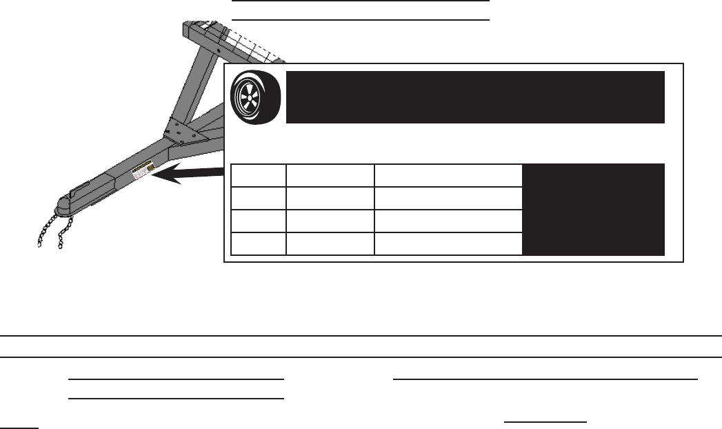
Tire and Loading Information Placard
TIRE AND LOADING INFORMATION
The weight of cargo should never exceed 430 kg or 950 lb.
TIRE SIZE COLD TIRE PRESSURE SEE OWNER’S
MANUAL FOR
ADDITIONAL
INFORMATION.
FRONT 4.80/4.00-8 410 kPa, 60 PSI
REAR NONE NONE
SPARE NONE NONE
12a MODEL 42709
The Tire and Loading Information Placard displays the cold tire ination pressure and the load limit for
this vehicle. See the Tire Care section for an explanation of tire pressure and see the Vehicle Load Limit
section following that for an explanation of load limit.

Page 22 For technical questions, please call 1-800-444-3353. Item 42709
Tire Size
To maintain safety, only purchase new tires of
the same size as the original tires. Look at the Tire
and Loading Information Placard, the Specications
Chart in this manual, or the sidewall of the tire being
replaced. If you have any doubt about selecting the
correct size, consult a tire dealer.
Tire Tread
The tire tread provides traction that prevents
your vehicle from slipping, especially if the road is
wet or icy. Tires are unsafe and should be replaced
when the tread is worn down to 1/16″. Measure
tread depth using a tread depth indicator (not
included).
Tire Rotation
Every 5,000 miles the left and right tires should
be switched. This will cause the tires to wear more
evenly and last longer.
Tire Balance and Alignment
The tires need to be balanced to prevent
vibration when driving. This involves attaching small
weights to the rim to offset small differences in rim
and tire weight. The tires also need to be aligned
properly. Alignment is the orientation of the tires to
the road surface and their being parallel. This helps
the tires to wear evenly, and provide better traction.
Both tire balance and alignment require specialized
equipment that is not provided with this vehicle.
Tire Repair
To properly repair a punctured tire, the hole
needs to be properly plugged and patched from the
inside of the tire. Tread punctures can be repaired
if they are not too large. Sidewall punctures should
not be repaired, the tire needs to be replaced if the
sidewall is damaged. Tires should be removed from
the rim to be inspected before being plugged and
patched. A qualied mechanic should remove the
tire from the rim, perform the repair, and remount
the tire.
VEHICLE LOAD LIMIT
Steps for Determining Correct Load
Limit
1. Locate the statement “The weight of cargo
should never exceed XXX kilograms or XXX
pounds” on your vehicle’s placard.
2. That gure equals the available amount of
cargo and luggage load capacity.
3. Determine the combined weight of luggage
and cargo being loaded on the vehicle. That
weight may not safely exceed the available
cargo and luggage load capacity.
4. If the trailer’s load exceeds the cargo and
luggage load capacity, then the trailer be
unsafe resulting in hazardous effects, such
as: Trailer’s tires will not be able to maintain
traction properly, and stopping distance will be
increased signicantly.
Page 23For technical questions, please call 1-800-444-3353.Item 42709
IMPORTANT
For safe use and operation, obey the following notices:
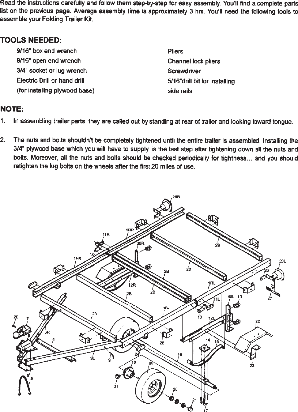
1. Read all instructions carefully and follow them step-by-step. Keep the instruction manual
in a safe place.
2. Double-check the assembly after you nish to ensure everything is assembled properly.
3. Follow the Trailer Licensing notice to properly license this trailer.
4. Inspect before every use; do not use if parts are loose or damaged.
5. Keep permanent labels in place and in good condition.
Notice:
• Repack bearings after every 3,000 miles of use.
• Maintain tires as explained in this manual.
• Comply with the following before every use:
1. Tighten U-bolt.
2. Tighten lug nut.
3. Tighten trigger lock on coupler.
4. Hook up safety chain.
5. Trailer load should not exceed 950 lb. capacity and must be properly secured.
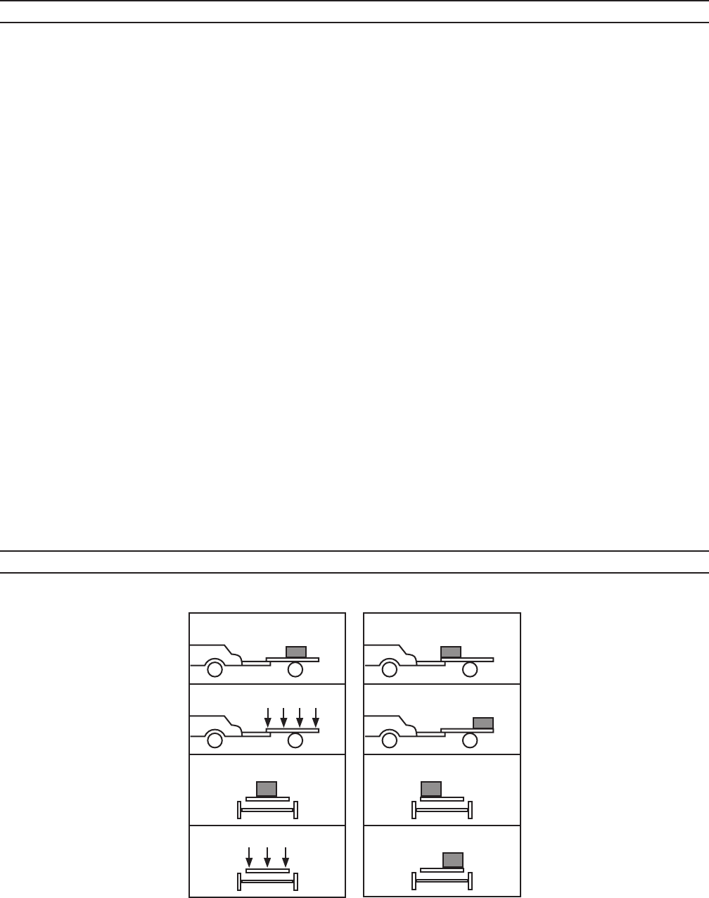
6. Trailer load size must not exceed trailer’s bed board size.
CORRECT WAY TO LOAD THE TRAILER
O
O
O
O
X
X
X
X
YES NO

3491 Mission Oaks Blvd. • PO Box 6009 • Camarillo, CA 93011 • (800) 444-3353
Limited 90 Day Warranty
Harbor Freight Tools Co. makes every effort to assure that its products meet high quality and
durability standards, and warrants to the original purchaser that this product is free from defects
in materials and workmanship for the period of 90 days from the date of purchase. This warranty
does not apply to damage due directly or indirectly, to misuse, abuse, negligence or accidents,
repairs or alterations outside our facilities, criminal activity, improper installation, normal wear
and tear, or to lack of maintenance. We shall in no event be liable for death, injuries to persons
or property, or for incidental, contingent, special or consequential damages arising from the use
of our product. Some states do not allow the exclusion or limitation of incidental or consequential
damages, so the above limitation of exclusion may not apply to you. THIS WARRANTY IS
EXPRESSLY IN LIEU OF ALL OTHER WARRANTIES, EXPRESS OR IMPLIED, INCLUDING THE
WARRANTIES OF MERCHANTABILITY AND FITNESS.
To take advantage of this warranty, the product or part must be returned to us with transportation
charges prepaid. Proof of purchase date and an explanation of the complaint must accompany the
merchandise. If our inspection veries the defect, we will either repair or replace the product at our
election or we may elect to refund the purchase price if we cannot readily and quickly provide you
with a replacement. We will return repaired products at our expense, but if we determine there is
no defect, or that the defect resulted from causes not within the scope of our warranty, then you
must bear the cost of returning the product.
This warranty gives you specic legal rights and you may also have other rights which vary from
state to state.
