Harman Becker Automotive Systems BE2728 BLUETOOTH AUTOMOTIVE INFOTAINMENT UNIT User Manual Antenna App Note
Harman Becker Automotive Systems, Inc. BLUETOOTH AUTOMOTIVE INFOTAINMENT UNIT Antenna App Note
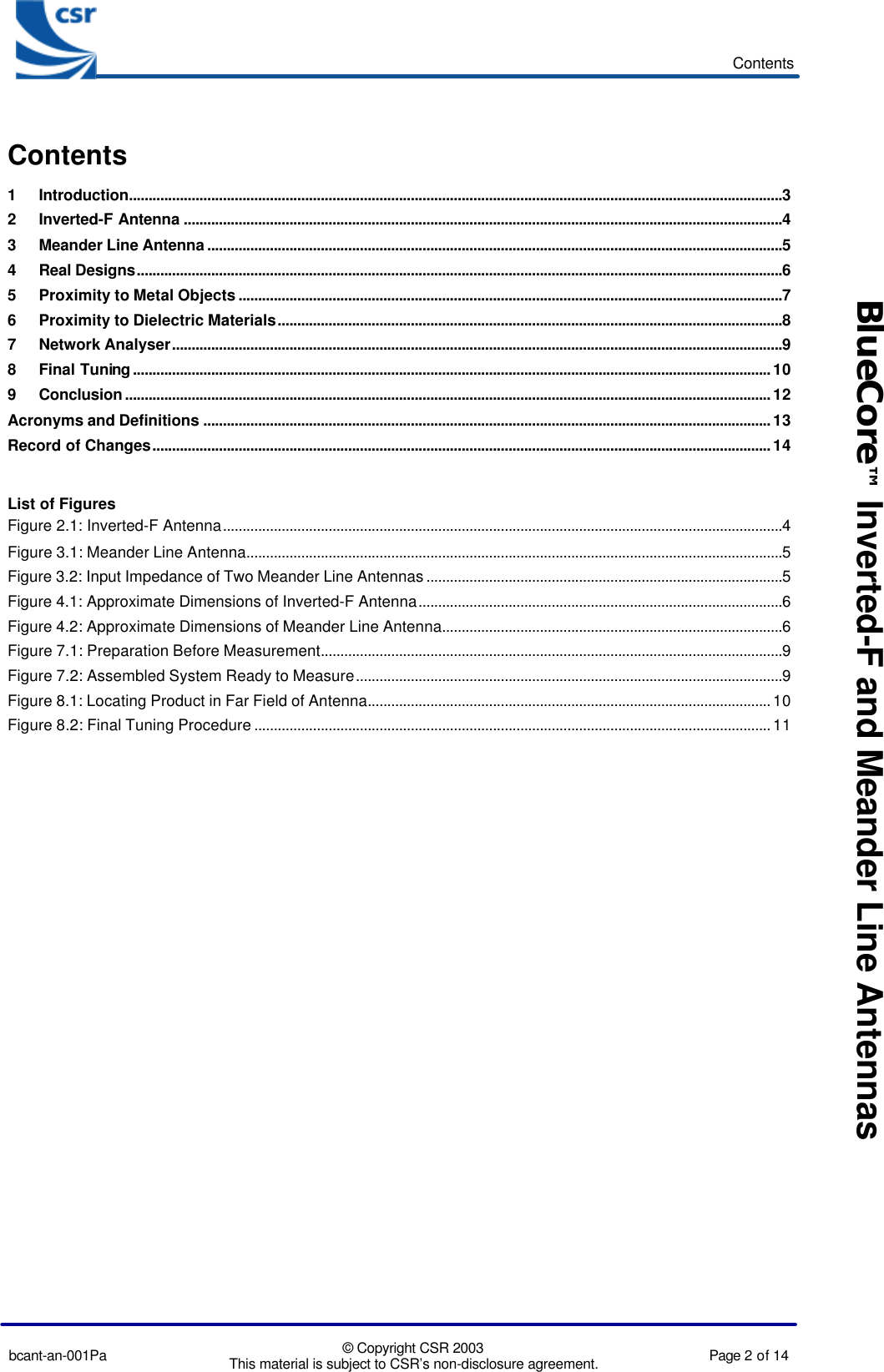
Contents
- 1. Antenna App Note
- 2. Users Guide
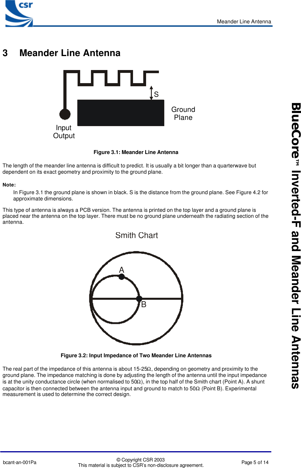
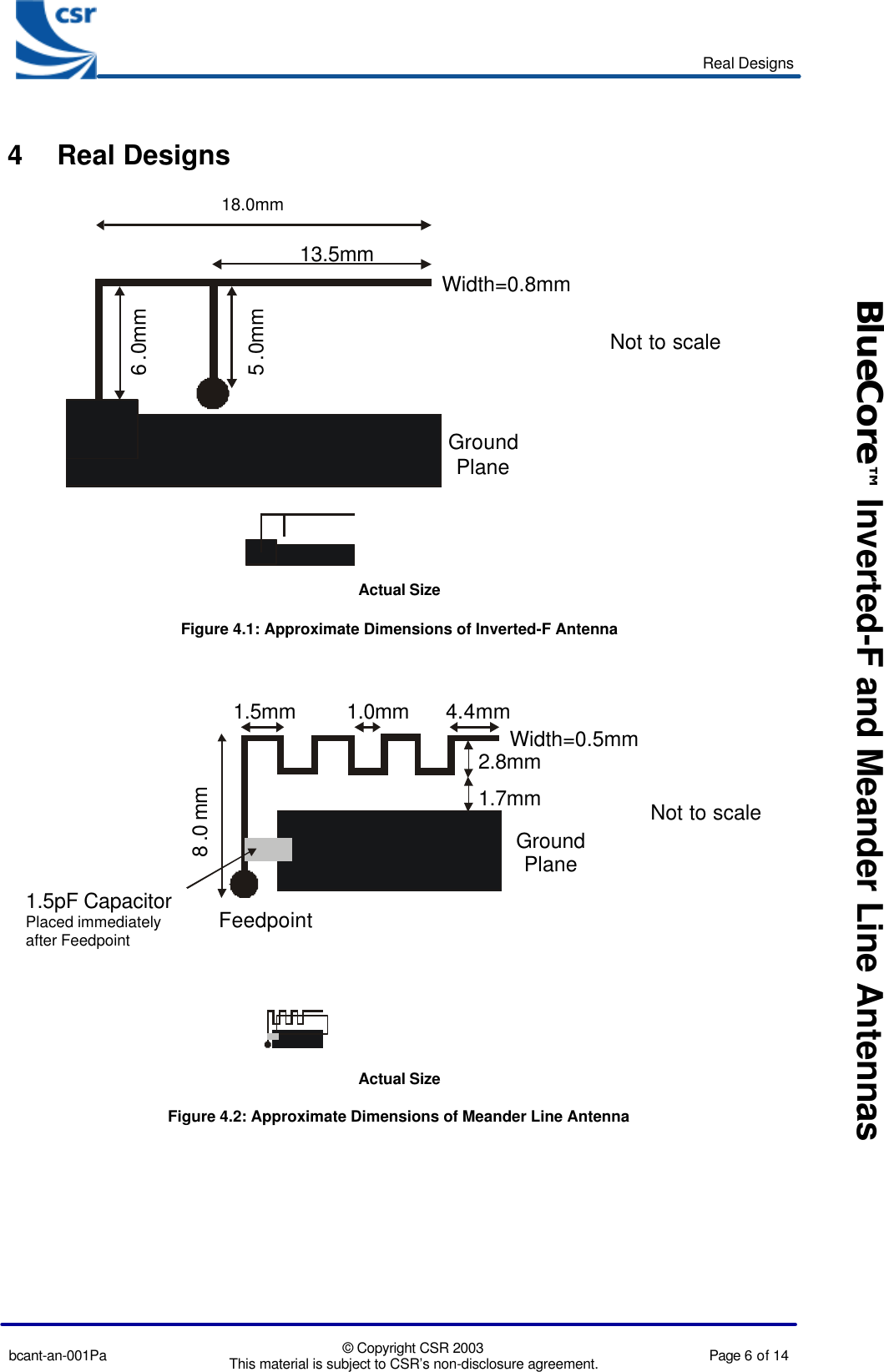
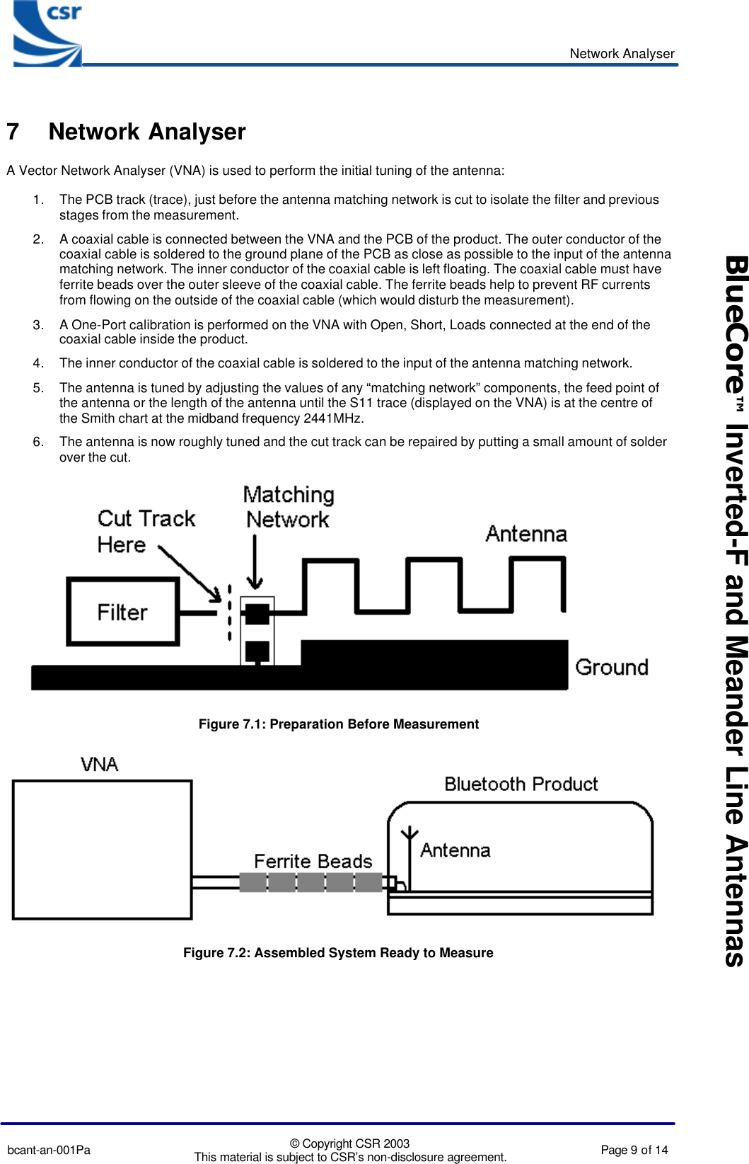
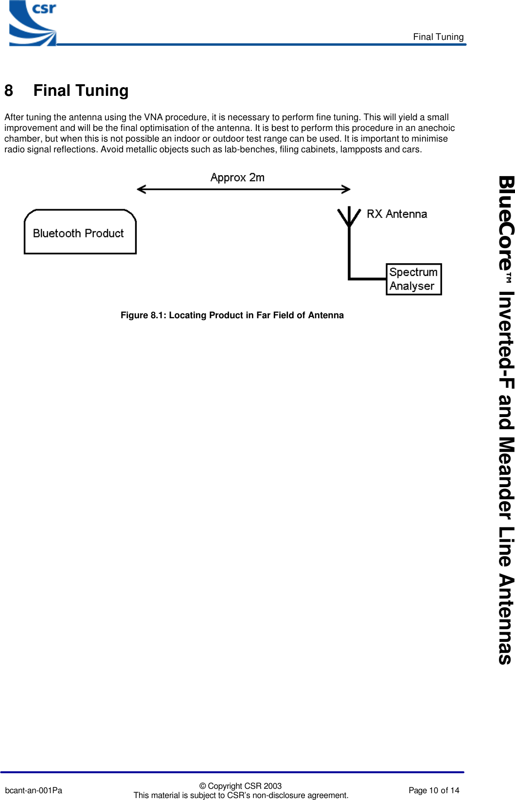
Antenna App Note