Harman Tl 2 0 Owner S Manual
2014-07-05
: Harman Harman-Tl-2-0-Owner-S-Manual harman-tl-2-0-owner-s-manual harman pdf
Open the PDF directly: View PDF ![]() .
.
Page Count: 40
Save These Instructions 3-90-08560 Rev: 8 October, 2013
Owner's Manual
Installation and Operation
Model:
TL2.0
Non-Catalytic, Top Load,
Wood Burning Room Heater
Item #1-90-856000
NOTICE
• Important operating and
maintenance instructions
included.
• Read, understand and
follow these instructions
for safe installation and
operation.
• Leave this manual with
party responsible for use
and operation.
PLEASE READ THIS ENTIRE MANUAL
BEFORE INSTALLATION AND USE OF
THIS WOOD-BURNING ROOM HEATER.
FAILURE TO FOLLOW THESE
INSTRUCTIONS COULD RESULT IN
PROPERTY DAMAGE, BODILY INJURY
OR EVEN DEATH.
• DO NOT STORE OR USE GASOLINE OR OTHER
FLAMMABLE VAPORS AND LIQUIDS IN THE
VICINITY OF THIS OR ANY OTHER APPLIANCE.
STARTS TO GLOW, YOU ARE OVERFIRING. CLOSE
AIR CONTROLS. OVERFIRING WILL VOID YOUR
WARRANTY.
COMBUSTIBLES AS SPECIFIED. FAILURE TO
COMPLY MAY CAUSE A HOUSE FIRE.
CHECK BUILDING CODES PRIOR TO INSTALLATION.
STATE AND NATIONAL CODES AND REGULATIONS.
AUTHORITIES HAVING JURISDICTION ABOUT
RESTRICTIONS, INSTALLATION INSPECTION, AND
PERMITS.
HOT, WILL CAUSE BURNS.
ROOM AS FIREPLACE.
HIGH TEMPERATURES.
HIGH TEMPERATURES MAY IGNITE CLOTHING
OR OTHER FLAMMABLE MATERIALS.
OTHER FLAMMABLE MATERIALS AWAY.
HOT SURFACES!
GLASS AND OTHER
SURFACES ARE HOT
DURING OPERATION AND
COOL DOWN.
TESTED AND APPROVED FOR USE WITH DRY,
SEASONED CORDWOOD ONLY. DO NOT BURN WET
OR GREEN WOOD. BURNING ANY OTHER TYPE OF
FUEL WILL VOID YOUR WARRANTY.
DO NOT DISCARD THIS MANUAL
Do Not
Discard
Wood Stove
Use & Care Video
CAUTION
!
CAUTION
!
WARNING
!
WARNING
!
Contact your local dealer with questions on installation,
operation or service.
2
TL2.0 Woodburning Stove
Dry Seasoned Wood Only! Save These Instructions3-90-08560
CAUTION: HOT WHILE IN OPERATION- DO
NOT TOUCH- KEEP CHILDREN AND CLOTHING AWAY-
CONTACT MAY CAUSE SKIN BURNS- SEE NAMEPLATE
AND INSTRUCTIONS. KEEP FURNISHINGS AND OTHER
COMBUSTIBLE MATERIALS A CONSIDERABLE DISTANCE
AWAY FROM THE APPLIANCE.
ATTENTION: CHAUD LORS DU FONCTIONNEMENT- NE
TOUCHEZ PAS L’APPAREIL-GARDEZ LES ENFANTS ET LES VÊTEMENTS
ÉLOIGNÉS- TOUT CONTACT PEUT ENTRAÎNER DES BRÛLURES DE LA
PEAU. RÉFÉREZ-VOUS À LA PLAQUE SIGNALÉTIQUE ET AU MODE
D’EMPLOI. GARDEZ LE MOBILIER ET LES AUTRES MATÉRIAUX
COMBUSTIBLES BIEN À L’ÉCART DE L’APPAREIL.
Report#/Rapport # 135-S-29-2
Tested to/Teste a: UL 1482-2011, UL 737-2011
LISTED SOLID FUEL FIREPLACE STOVE OR ROOM HEATER
APPAREIL DE CHAUFFAGE OU POELE A COMBUSTIBLE SOLIDE
MODEL/MODELE: TL 2.0
SERIAL NUMBER/NUMERO DE SERIE:
Prevention des incendies:
Respectez scrupuleusement les instructions du constructeur pour l’installation et l’utilisation. Respectez les regles et normes applicables dans
votre region. Dans tous les cas, l’installation devra au minimum satisfaire aux exigences de NFPA 211 Etats-Unis. Reportez vous aux instructions
du fabricant et aux regles locales pour les precautions necessaires lors du passage des tuyaux de fumee a travers un mur ou un plafond
combustible. Controlez et nettoyez frequemment la cheminee et les tuyaux de fumee selon les instructions du fabricant.
N’UTILISIXZ QUE DU BOIS EN BUCHES:
Ne pas raccorder ce poele a un conduit de fumee utilise pour un autre appareil. Le tuyau de fumee doit avoir 6” de diametre minimum,
et etre en acier de qualite 24 MSG noir. Le conduit de fumee peut etre maconne ou de fabrication industrielle type ULC S629.
Nota: Ne remplacer la vitre qu’avec une vitre ceramique de 45 mm disponible chez votre fournisseur.
Controlez et Nettoyez Frequemment la Cheminee et les Tuyaux de Fumee. Dans Certaines Conditions D’utilization, des Accumulations
de Cresote Peuvent se Produire Rapidement.
NE PAS SUR CHAUFFER - SI LE POELE OU LE TUYAU ROUGISSENT, VOUS SURCHAUFFEZ
PREVENT HOUSE FIRES: Install and Use Only in Accordance With Manufacturer’s Installation and Operating Instructions as well as Local Codes.
In absence of any local codes, installation must meet minimum requirements of NFPA 211 in USA. Refer to manufacturer’s instructions and all
local codes for requirements for passing chimney through a combustible wall or ceiling.
FOR USE WITH SOLID WOOD FUEL ONLY. Do NOT Connect This Unit to a Chimney Flue Serving Another Appliance.
Flue connector pipe must be 6” diameter, minimum 24 MSG black steel. Chimney must be factory built UL 103HT or a tile lined masonry.
Inspect and Clean Chimney Frequently - Under Certain Conditions of Use, Creosote Buildup May Occur Rapidly.
NOTE: Replace glass only with 5mm ceramic glass available from your dealer.
DO NOT OVERFIRE - IF HEATER OR CHIMNEY CONNECTOR GLOWS, YOU ARE OVERFIRING.
Meets requirements of ULC S627-00/Selon les exigences de ULC S627-00
Fireplace Stove, Also For Use In Mobile Homes In US only-With Outside Air Adapter #1-10-856082
E
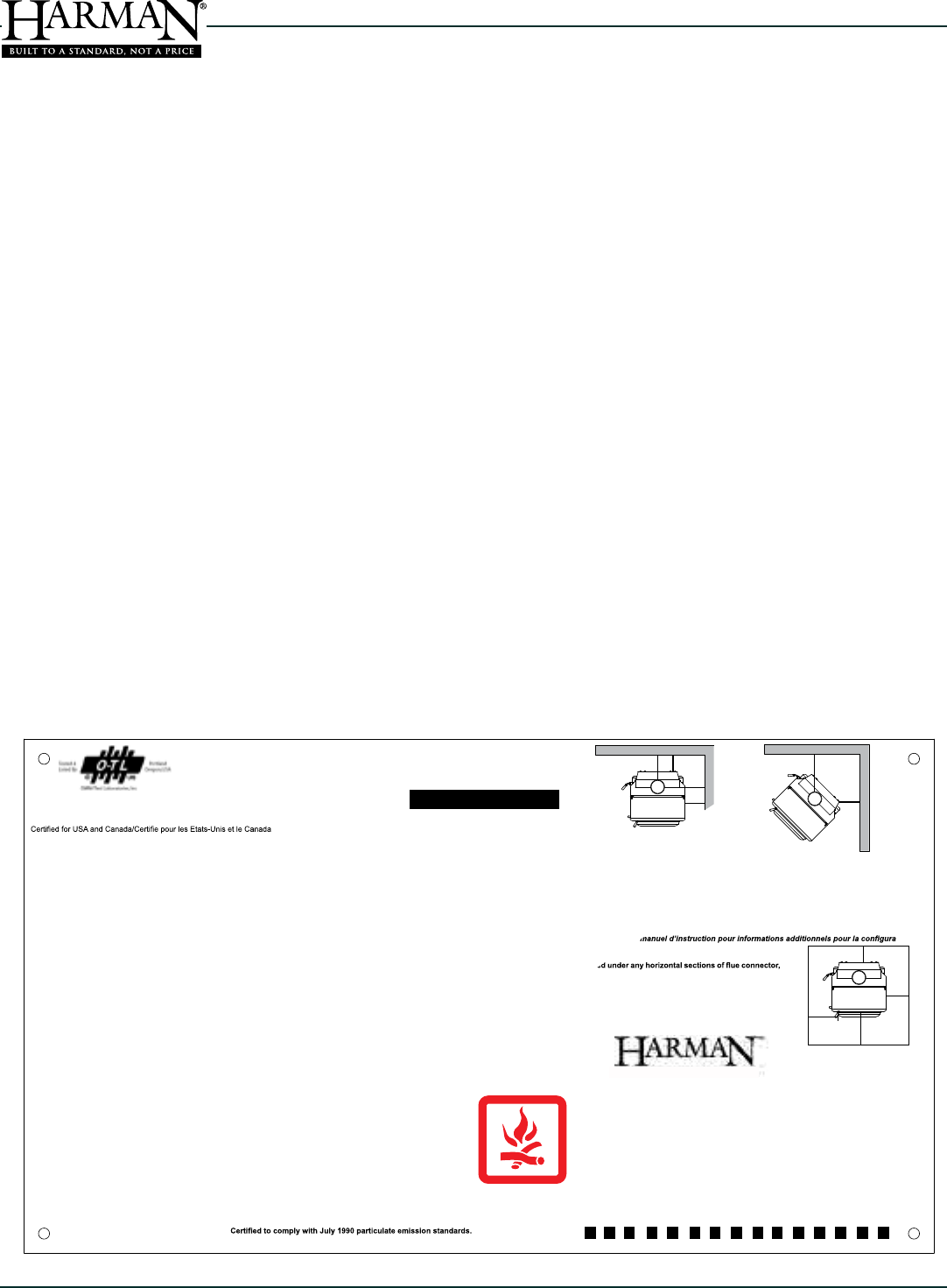
CLEARANCE TO COMBUSTIBLE SURFACES
A - Unit to Sidewall
B - Unit to Backwall
C - Chimney Connector to Sidewall
D - Chimney Connector to Backwall
E - Unit to Adjacent Wall
F - Chimney Connector to Adjacent Wall
14”
13”
24”
18”
16”
22.5”
A
C
B
D
DISTANCES MINIMALES DE SECURITE
A - Entre le mur lateral et l’appareil
B - Entre le mur arriereet l’appareil
C - Entre le tuyau et le mur lateral
D - Entre le tuyau et le mur arriere
E - Entre le mur adjacent et l’appareil
F - Entre le tuyau et le mur adjacent
356 mm
330 mm
610 mm
457 mm
406 mm
571 mm
8”
8”
8”
16”
200mm
18”
200mm
(200 mm)
457 mm
Floor protection must be a non-combustible material. Must
extending 2” (51mm) beyond each side of the connector.
Pour protéger le plancher, il faut sous le poêle un matériau.
Qui doit aussi être placé sous les parties horizontales du tuyau
de raccord à la cheminée et s’étendre à 51 mm (2 po) au-delà
de lateral du tuyau.
REFER TO PRODUCT MANUAL FOR CLEARANCES WITH ADDITIONAL VENT CONFIGURATIONS.
-
tion de la ventilation.
CONTACT LOCAL BUILDING OR FIRE OFFICIALS ABOUT RESTRICTIONS AND INSTALLATION INSPECTION IN YOUR AREA.
CONSULTEX LES ADMINISTRATIONS ET ORGANISMES COMPETENTS POUR LA CONSTRUCTION ET LA PREVENTION DES
INCEDIES AFIN DE RESPECTER LES REGLES DE SECURITE EN VIGUEUR.
Made in U.S.A. of US and imported parts. / Fabriqué aux États-Unis-d’Amérique par des pièces d’origine américaine et pièces importées.
2011 2012 2013 JAN FEB MAR APR MAY JUN JUL AUG SEP OCT NOV DEC
U.S. ENVIRONMENTAL PROTECTION AGENCY:
Date of Manufacture/Date de fabrication:
:rap éuqirbaF / yb derutcafunaM
352 Mountain House Road-Halifax, PA 17032 (É.-U.)
F
008
This unit is approved for cooking using Harman grill #1-00-08121 - KEEP BYPASS DAMPER OPEN.
Cet appareil est aussi approuvé pour utiliser la grille de cuisson Harman # 1-00-08121 - L'AMORTISSEUR DE DÉVIATION DOIT ÊTRE OUVERT
Use ONLY Optional Blower Part # 1-00-856002. Pour ventiateur en option no, 1-00-856002 Seulemente.
CAN
USA
DANGER: Risk of Fire or Explosion - Do not burn garbage, gasoline, drain oil or other flammable liquids./ Risque d’incendie ou d’explosion.
Ne brûlez pas d’ordures, d’essence, d’huile de vidange ni aucun autre liquide inflammable. Do not burn coal / Ne chauffez pas TROP
May be burned as a fireplace with “Cozy Screen” Part# 3-40-06960 in place over door opening. Otherwise, doors must remain closed during operation
Peux fonctionner comme un foyer avec la pièce no. 3-40-06960 ‘’ Cozy Screen ‘’ placée au dessus de l’ouverture de la porte. Autrement , les portes
doivent demeurer fermées durant le fonctionnement.
Hearth & Home Technologies welcomes you to our tradition of excellence! By choosing a Harman appliance, you have become
part of our commitment to meeting the heating needs of consumers with the most distinctive, powerful and responsible home
heating products available.
With it's compact, steel-body construction, the TL2.0 features a heating capacity of 1600 to 1900 ft². The TL2.0 takes advantage
of Harman’s 30+ years of stove design, technology and manufacturing. The Firedome Plus secondary combustion system
provides for super-clean burning and minimal maintenance. The top-loading feature makes for more convenient loading,
with enough fuel for an all day burn.
We wish you and your family many years of enjoyment in the warmth and comfort of your hearth appliance.
Thank you for choosing Harman.
Harman® A division of
Hearth & Home Technologies
352 Mountain House Road
Halifax, PA 17032
www.harmanstoves.com
When This Room Heater Is Not Properly Installed, a House Fire May Result. To Reduce The Risk Of Fire, Follow The
Requirements In Your Area.
This Label is located on the rear of the appliance. It contains important safety test information as well as the
clearances to combustible materials. The label also contains the appliance serial number. For your records, copy
your serial number and purchase date here.
Serial #: ________________________ Date of Purchase: ________________________
SAMPLE LABEL

3
Dry Seasoned Wood Only!
TL2.0 Woodburning Stove
Save These Instructions 3-90-08560
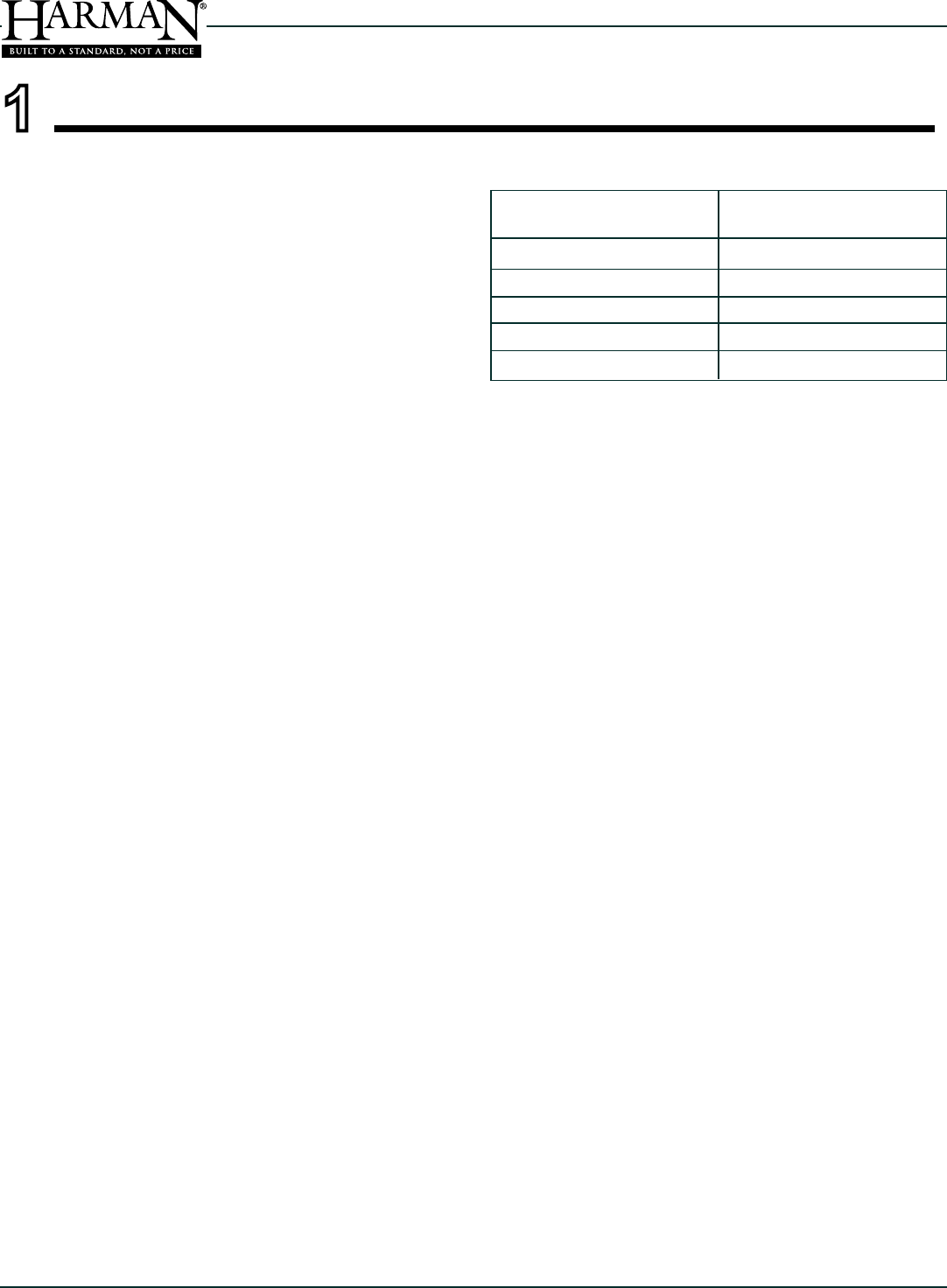
TABLE OF CONTENTS
Section 1: Listing and Code Approvals
A. Appliance Certications 4
B. Mobile Home Approval 4
C. Glass Specications 4
D. Electrical Rating 4
E. BTU & Efciency Specications 4
Section 2: Special Warnings and Notes
A. Carbon Monoxide Warnings &
Considerations 5
Section 3: Getting Started
A. Design, Installation & Location 6
B. Fire Safety 6
C. Component Locator 7
D. Pre-Use Checklist 8
Section 4: Dimensions & Clearances
A. Appliance Dimensions 9
B. Clearances to Combustibles 10
C. Floor Protection 12
Section 5: Chimneys and Venting
A. Draft 13
B. Chimney Connectors 13
C. Wall Pass-Throughs 13
D. The Chimney 14
A. Mobile Home Installation 20
Section 7: Appliance Set-Up
A. Outside Air Attachment 21
B. Leveling The Appliance 21
C. Optional Cooking Grill 21
D. Optional Blower Kit 22
E. Top Air Grill Option 22
F. Brushed Stainless Trim option 22
Section 8: Operating Instructions
A. Fuel Specications 23
B. General Operating Information 23
C. Burning as a Fireplace 24
D. Combustion Process 24
E. User Controls 25
F. Before Your First Fire 25
G. Building & Maintaining a Fire 25
Section 9: Service & Maintenance
A. Soot Formation (Removal) 27
B. General Maintenance Procedures 28
Section 10: Reference Materials
A. Wiring Diagram (Blower Option) 30
B. Service Parts Listing 31
C. EPA Hang Tag 34
D. Warranty Policy 35
HT chimneys in the standard for Chimneys, Factory-
Built, Residential Type and Building Heating Appliance,
UL 103
OR
= Contains updated information
4
TL2.0 Woodburning Stove
Dry Seasoned Wood Only! Save These Instructions3-90-08560
Model: TL2.0 Woodburning Stove
Laboratory: OMNI-Test Laboratories, Inc.
Report No. 135-S-29-2
Type: Solid Fuel Room Heater / Wood
Burning Type.
Standard(s): UL1482-11, UL737-11 &
ULC S627-00
This appliance is also approved for installation in a
shop.
This appliance is approved for Installation in mobile/
manufactured homes in the US only. The structural
integrity of the mobile home oor, ceiling and walls must be
maintained. The appliance must be properly grounded to
the frame of the mobile home, and must never be installed
in a room designated for sleeping. The unit must have
provisions for an outside air source when installed in a
mobile home.
This appliance is equipped with 5mm ceramic glass. Replace
glass only with 5mm ceramic glass. Please contact your
dealer for replacement glass if needed.
D. Electrical Rating
Optional Blower: 115 VAC, 60 Hz. <1 Amps
*BTU input based on EPA test fuel. Actual cordwood values
will vary.
††Heating capacity based on zones 1 and 2, covering the
Northern United States.
Particulate Emissions
Rating:
*BTU Input:
Heating Capacity:
Firebox Size:
Fuel:
Shipping Weight:
2.0 cu. ft.
Dry Cordwood
452 lbs.
1,600-1,900 sq. ft.††
9,600 - 31,800 / hr
2.6g/hr Avg
1 Listing and Code Approvals
5
Dry Seasoned Wood Only!
TL2.0 Woodburning Stove
Save These Instructions 3-90-08560
NEVER CONNECT THIS UNIT TO A CHIMNEY FLUE
SERVING ANOTHER APPLIANCE.
throughout the heating season and at the end of each
DO NOT CONNECT TO ANY AIR DISTRIBUTION DUCT
OR SYSTEM.
SPECIAL NOTE:
DUE TO ASH BUILDUP, IT IS STRONGLY RECOMMENDED
TO HAVE YOUR STOVE PROFESSIONALLY CLEANED
AND SERVICED ANNUALLY. THIS INCLUDES ALL
PARTS OF THE STOVE, AND THE VENTING SYSTEM.
Carbon monoxide, referred to as CO, is a colorless,
odorless gas that is produced during combustion of wood
and other fuels.
This appliance is a natural draft system which relies on
a properly designed chimney to remove CO and other
combustion by-products from the stove.
Even though this stove is designed to be as safe as
possible, it is important that you install a CO detector.
This is true for oil, gas, or coal burning products as well.
CO is not specically heavier or lighter than air. Therefore,
it is best to install the detector at table top level rather than
on the ceiling like a smoke detector.
CO detectors are very sensitive and may sound an alarm
for fumes other than CO or CO from sources other than
the stove such as car or lawn mower exhaust.
If the alarm sounds
1. Increase ventilation by opening windows or doors.
2. Make sure the stove doors and lid are closed and
latched.
3. Check stove for smoking or pufng condition. Open by-
pass and increase air-ow to rebox, if needed.
4. Check chimney for possible blockage or down-draft.
5. Check for false alarm.
Never use gasoline, lantern fuel, kerosene, charcoal
the heater while it is in use.
2 Special Warnings and Notes
6
TL2.0 Woodburning Stove
Dry Seasoned Wood Only! Save These Instructions3-90-08560
SERVICING ANOTHER APPLIANCE.
DUCT OR SYSTEM.
B. Fire Safety
Maintain the designated clearances to combustibles.
Insulation must not touch the chimney. You must maintain
the designated air space around the chimney. This space
around a chimney is necessary to allow natural heat
removal from the area. Insulation in this space will cause
a heat buildup, which may ignite wood framing. NOTE:
To provide reasonable re safety, the following should be
given serious consideration:
1. Install at least one smoke detector on each oor of
your home. Detectors should be located away from
the heating appliance and close to sleeping areas.
Follow the smoke detector manufacturer's placement
and installation instructions, and be sure to maintain
regularly.
2. A conveniently located Class A re extinguisher to
contend with small res resulting from burning embers.
3. A practiced evacuation plan, consisting of at least two
escape routes.
4. A plan to deal with a chimney re as follows:
In the event of a chimney re:
a. Evacuate the house immediately.
b. Notify Fire Department.
c. Never apply water to a suspected chimney re.
Serious damage could occur.
DO NOT OPERATE APPLIANCE
BEFORE READING AND
UNDERSTANDING THE OPERATING
INSTRUCTIONS.
FAILURE TO OPERATE PROPERLY
MAY CAUSE A HOUSE FIRE.
A. Design, Installation & Location Considerations
1. Appliance Location
Consideration must be given to safety, convenience, trafc
ow, and the fact that the appliance will need a chimney and
chimney connector. It is a good idea to plan your installation
on paper, using exact measurements for clearances and
oor protection, before actually beginning the installation.
When installing on a combustible oor, proper oor
protection material must be used. See page 12 for details.
Maintain specied vent clearance to combustible
requirements listed by the vent manufacturers instructions
and all clearance to combustibles listed in this manual.
Check with your local building code agency before you begin
your installation. Be sure local codes do not supersede UL
specications and always obtain the required permit so
that insurance protection benets cannot be unexpectedly
cancelled. If any assistance is required during installation,
please contact your dealer.
We recommend that a qualied building inspector and your
insurance company representative review your plans before
and after the installation.
Be sure to provide a source of fresh air to the room or
directly to the appliance. Make-up air is needed to replace
what the chimney draws away through the appliance.
Consider attaching outside air to the appliance. Certain
conditions can create negative pressure within the dwelling.
When this occurs, you may have trouble operating the wood
stove. Worse yet, it may be strong enough to allow smoke
leakage from the appliance. Installation on lower levels and
in basements can be especially affected.
3 Getting Started
CAUTION
!
WARNING
!
7
Dry Seasoned Wood Only!
TL2.0 Woodburning Stove
Save These Instructions 3-90-08560
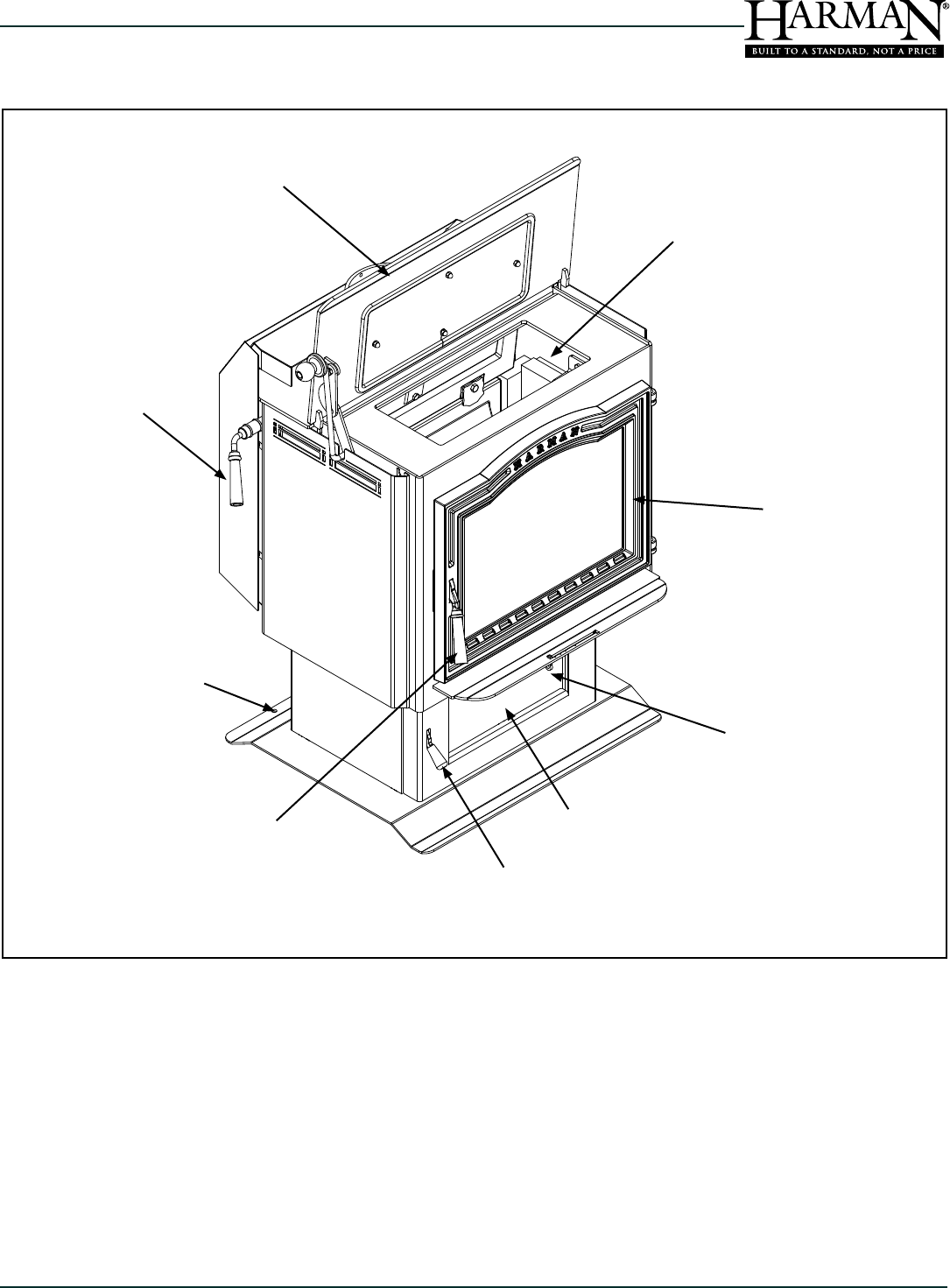
C. Component Locations
Top Load Opening
Air Control
Front Load Door
Top Load Door
Bypass Damper
Control Handle
Ash Door
Ash Door
Latch
Front Load
Door Latch
Bolt-Down Holes for Mobile
Home Installations
8
TL2.0 Woodburning Stove
Dry Seasoned Wood Only! Save These Instructions3-90-08560
D. Pre- Use Check List
1. Place the appliance in a location near the
nal installation and follow the procedures
below:
2. Open the appliance and remove all articles
packed inside. Inspect all items for shipping
damage. Notify dealer of any missing or
damaged goods.
3. All safety warnings have been read and
followed precisely.
4. This Owner's Manual has been read in it's
entirety.
5. Floor protection requirements have been
read and followed.
6. The ue connector has been installed in
accordance with the instructions herein.
7. The proper clearances from the appliance
and chimney connector to combustibles
have been met.
8. The masonry chimney has been cleaned
and inspected by a professional, or the
factory built metal chimney is installed
according to the manufacturers instructions.
9. The chimney meets the minimum height
requirements.
10. All labels and hang tags have been removed
from the glass.
11. All plated surfaces have been wiped clean,
if applicable.
12. The optional air distribution blower
has been installed properly.
13. A properly grounded electrical receptacle is
available within reach of the blower's power
cord (if installed).
INSPECT APPLIANCE AND COMPONENTS
FOR DAMAGE. DAMAGED PARTS MAY
IMPAIR SAFE OPERATION.
DO NOT INSTALL DAMAGED
COMPONENTS.
DO NOT INSTALL INCOMPLETE
COMPONENTS.
DO NOT INSTALL SUBSTITUTE
COMPONENTS.
REPORT DAMAGED PARTS TO DEALER.
FIRE RISK.
HEARTH & HOME TECHNOLOGIES
DISCLAIMS ANY RESPONSIBILITY FOR,
AND THE WARRANTY WILL BE VOIDED
BY, THE FOLLOWING ACTIONS:
WARNING
!
WARNING
!
INSTALLATION AND USE OF ANY DAMAGED
APPLIANCE.
MODIFICATION OF THE APPLIANCE.
INSTALLATION OTHER THAN AS INSTRUCTED
BY HEARTH & HOME TECHNOLOGIES.
INSTALLATION OF PARTS OR COMPONENTS
NOT SUPPLIED OR APPROVED BY HEARTH &
HOME TECHNOLOGIES.
OPERATING APPLIANCE WITHOUT THE LEGS
ATTACHED.
OPERATING APPLIANCE WITHOUT FULLY
ASSEMBLING ALL COMPONENTS.
DO NOT OVERFIRE.
OR ANY SUCH ACTION THAT MAY CAUSE A FIRE
9
Dry Seasoned Wood Only!
TL2.0 Woodburning Stove
Save These Instructions 3-90-08560
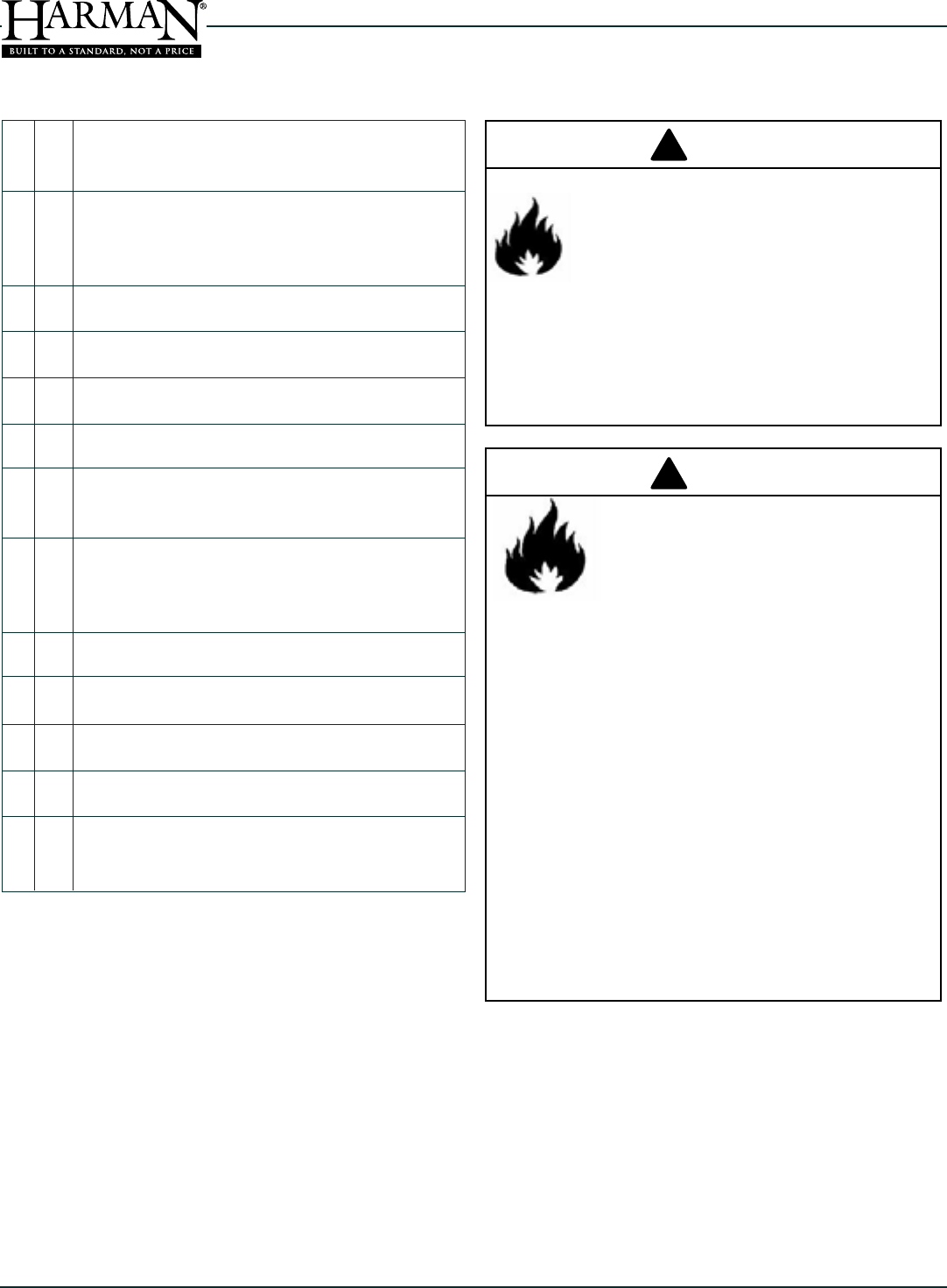
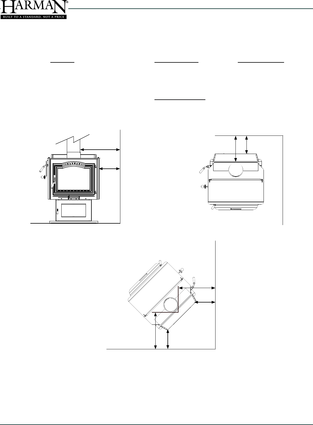
A. Appliance Dimensions
The Harman TL2.0 meets the U.S. Environmental
Protection Agency’s emission limits for wood heaters
sold after July 1, 1990.
Weight..........................................452 lbs
Flue Size........................................6 inch
Log Length Recommended........... 18"
Average Emissions.......................2.6 Grams Per Hr.
Outside Air size.............................4.5 inch I.D.
23.9"
32.3"
35.3"
18.4"
Air Intake
Centered
9.1"
26.0"
4 Dimensions & Clearances
10
TL2.0 Woodburning Stove
Dry Seasoned Wood Only! Save These Instructions3-90-08560
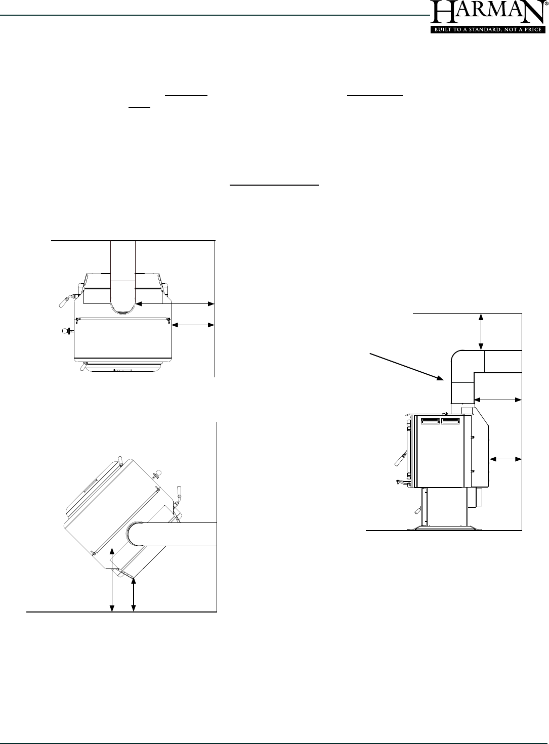
*For clearance reduction methods, refer to NFPA 211 or Local Codes
B
D
A
C
FE
F
E
Location Single-wall Pipe
A Unit to Side Wall 14" / 356 mm 14" / 356 mm
B Unit to Back Wall 13" / 330 mm 7" / 178 mm
C Vent Pipe to Side Wall 24" / 610 mm 24" / 610 mm
D Vent Pipe to Back Wall 18" / 457 mm 12" / 305 mm
Corner Installation
F Connector to Wall 22.5" / 571 mm 16.5" / 419 mm
11
Dry Seasoned Wood Only!
TL2.0 Woodburning Stove
Save These Instructions 3-90-08560
*For clearance reduction methods, refer to NFPA 211 or Local Codes
Location Single-wall
Pipe
A Unit to Side Wall 13" / 330 mm
B Unit to Back Wall 13" / 330 mm
C Vent Pipe to Side Wall 23" / 584 mm
D Vent Pipe to Back Wall 18" / 457 mm
E Vent Pipe to Ceiling 16" / 406 mm
Corner Installation
G Connector to Wall 22.5" / 571 mm
A
C
GF
E
B
D
E
2' (610 mm) Minimum vertical
prior to elbow.
12
TL2.0 Woodburning Stove
Dry Seasoned Wood Only! Save These Instructions3-90-08560
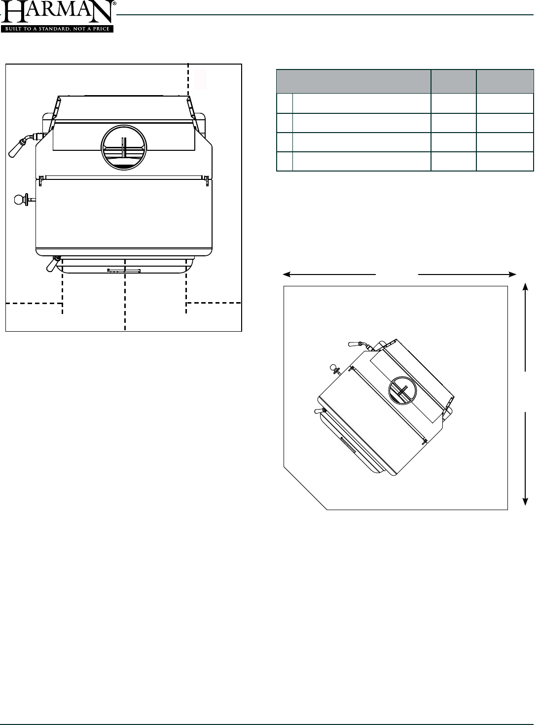
C. Floor Protection Requirements Minimum Size oor protection (USA) is 48" Deep By 32.5"
Wide.
Floor Protection Requirements
If the appliance is being installed on a combustible oor,
non-combustible oor protection must be installed. In all
installations, the area under and around the stove must
be protected from falling ash and live coals. The area
under a horizontal run of chimney connector must also be
protected, extending two (2) inches (51mm) to each side of
the horizontal connector.
Further guidelines for oor protection are as follows: In the
U.S. the oor protector must be completely under the stove,
and extending 18" in front of the door opening, 8" to each
side of the door opening, and 8" to the back.
In Canada, the oor protection must extend 18" (457mm) in
front of the door opening, and 8" (203mm) to each side of
the appliance, and to the rear.
* Floor protection dimensions for the front and sides are
measured from the appliance door opening in The United
States. In Canada, the side dimension is measured from the
widest part of the appliance.
Minimum 60" corner oor protection (CANADA).
JJ K
L
54"
54"
L
J
Floor Protection
Requirements Inches Millimeters
Sides- USA /CANADA *
Rear- USA
8 203
8 203
LRear- CANADA Wall Wall
KFront- USA /CANADA * 16 457
Alternate oor protector dimension may be used as long
as they satisfy the measurement requirements shown
above.
Minumum size oor protection for a corner installation
hearth pad is 54" x 54" (USA ONLY).

13
Dry Seasoned Wood Only!
TL2.0 Woodburning Stove
Save These Instructions 3-90-08560
5 Chimneys & Venting
A. Draft
Draft is widely misunderstood. It is important that you, the
stove operator, realize that draft is a variable effect, not a
given quantity. Stoves and chimneys do not have draft, yet
draft is the key to your stove’s performance.
Draft is a force, produced by an operating stove and the
chimney to which it is attached. It is created by hot gases
rising up the chimney, creating a pressure difference between
the inside of your home and the outside air. It continually
moves fresh combustion air into the stove, and hot exhaust
gases out of the stove; without this constant ow, the re
will go out.
Other factors, such as barometric pressure, winds, the
airtightness of the home, the total inside chimney volume,
chimney height and the presence of venting devices such
as exhaust fans also play a role in maintaining an adequate
draft. Low barometric pressures, super insulated homes
and exhaust fans can reduce draft; winds can play havoc
with draft; and too large or too small a chimney volume can
cause reduced draft due to the excessive cooling or not
enough room to vent exhaust gases. Introducing outside air
directly to the stove may help remedy a low draft problem.
Some signs of inadequate draft are smoking, odor, difculty
in maintaining the re, and low heat output. Overdraft can be
caused by a very tall chimney even if it is the recommended
size, and can cause overring of your stove. Signs of an
overdraft include rapid fuel consumption, inability to slow
the re, and parts of the stove or chimney connector glowing
red. It is important that you follow the chimney guidelines in
this manual, including size, type, and height to avoid draft
problems.
When installed and operated according to this manual, the
stove will produce enough hot gases to keep the chimney
warm so that adequate draft is maintained throughout the
burn cycle.
B. Chimney Connectors
In general, following these guidelines will ensure compliance
with all national and provincial codes; prior to beginning your
installation, check with your local building code ofcial to
check on additional local regulations which may inuence
the design and placement of your venting system.
The Harman TL2.0 may be installed with a minimum (.6 mm)
24 gauge blue or black steel, chimney connector pipe. The
size of the connector should correspond to the size of the ue
collar opening, which is 6" (152mm). Do not use makeshift
compromises. No part of the chimney connector may pass
through an attic or roof space, closet or other concealed
space, or through a
floor or ceiling. Whenever possible, avoid passing the
connector through a combustible wall; if you must, use an
approved wall pass-through, described later in this section.
Assemble the connector beginning at the ue collar, with
the crimped ends pointing towards the stove (to keep debris
or residue inside the system). Each joint, including the one
to the stove’s ue collar and the one to the chimney itself
should be secured with at least three sheet metal screws.
Screws may be a maximum of 3 inches apart. A 1-1/4" (30
mm) overlap is required at each joint, including the ue collar
attachment. No more than two 90 degree elbows should be
used, and the total length of connector should not exceed
10 feet (3 m). All horizontal runs of connector must have a
minimum upward slope of 1/4" per foot (20 mm per meter).
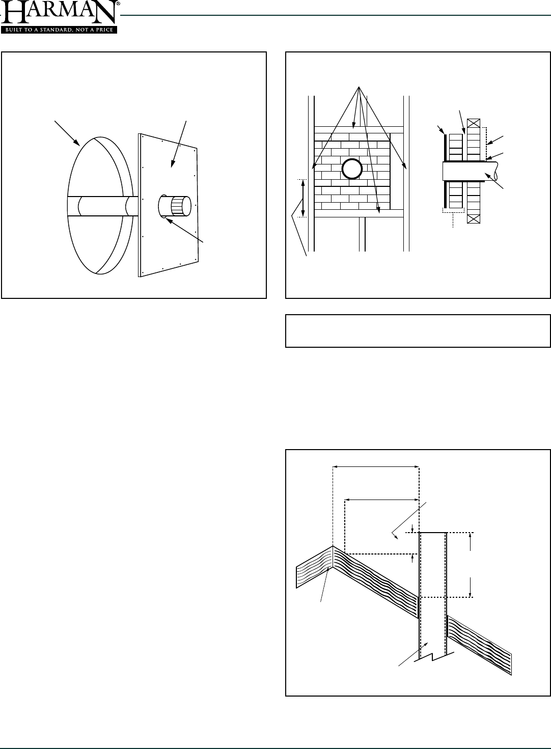
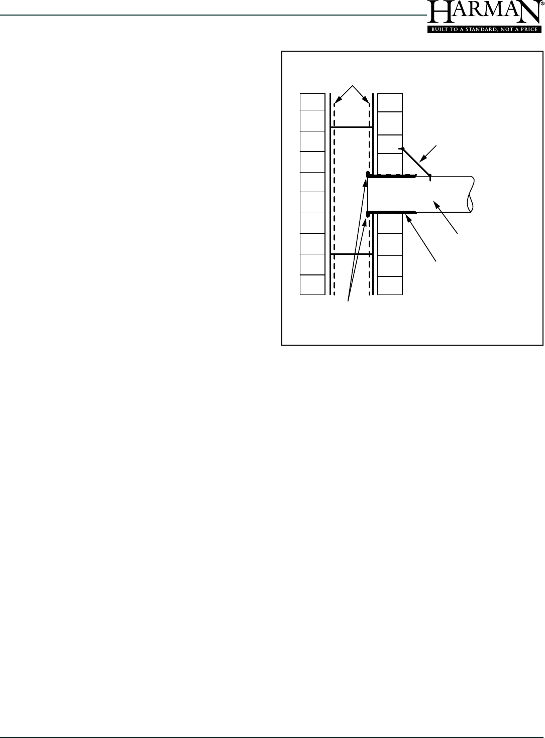
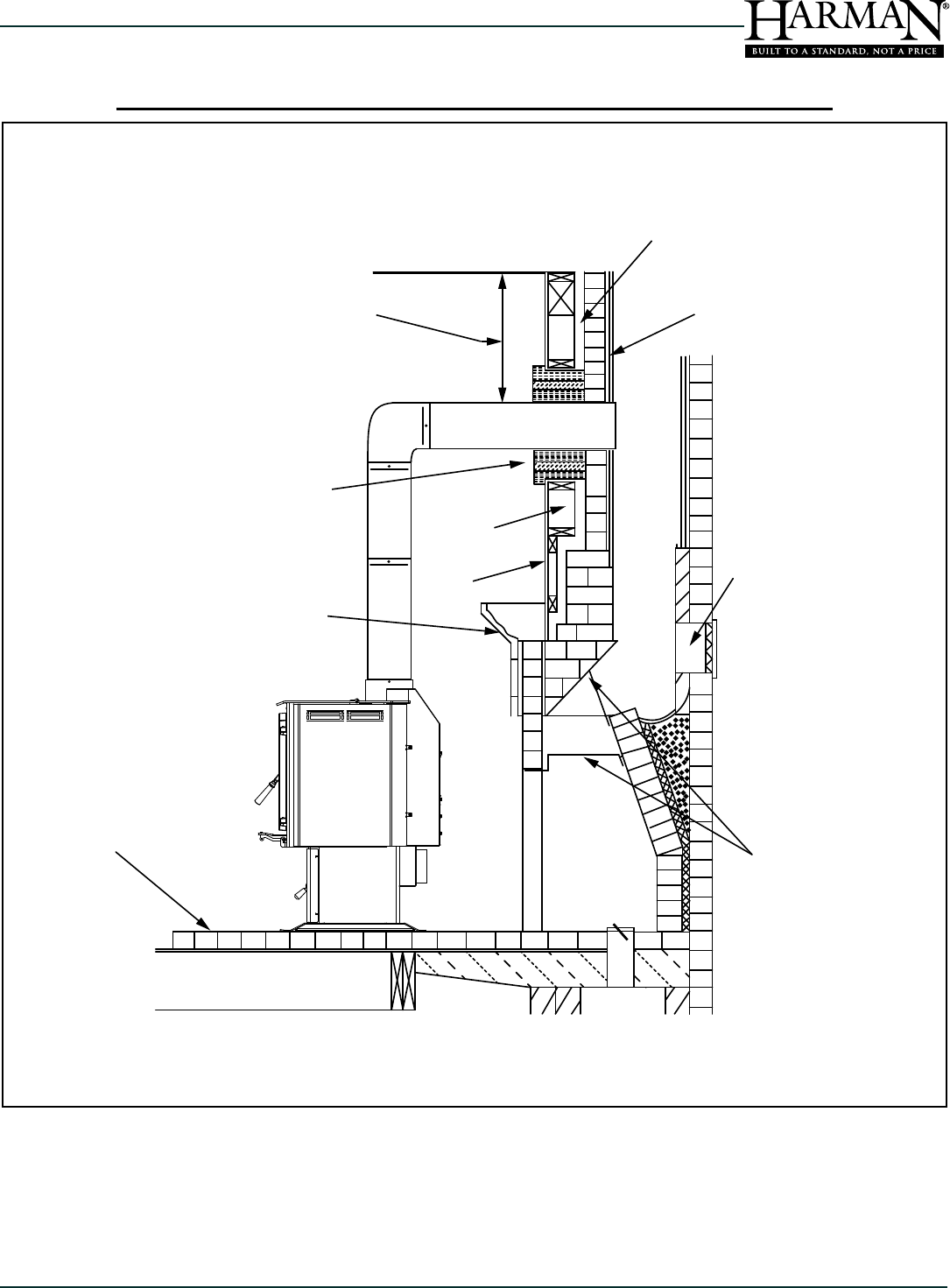
C. Wall Pass-thrus
Depending on your local building codes, and the pertinent
provincial or national codes, there are several choices for
passing the chimney connector safely through a wall. Before
beginning your installation, contact local ofcials, and also
the chimney connector and chimney manufacturer for specic
requirements.
Canada. Three methods are approved by the Canadian
Standards Association. The diagram on the next page shows
one method requiring an 18"(450 mm) air space between the
connector and the wall. It allows use of one or two covers
as described in the diagram. The two other methods are
described in detail in the current issue of CAN/CSA B365,
the national standard.
United States In the U.S., the national code is NFPA 211.
While many localities adopt this standard, be sure to check
with local authorities before beginning your installation.
The NFPA (National Fire Protection Agency) permits four
methods for passing through a combustible wall. A commonly
used method to pass through a wall directly to a masonry
chimney is to clear a minimum 12"(300 mm) around the entire
chimney connector, and ll it with brick masonry which is at
least 3.5"(90 mm) thick. A reclay liner, minimum 3/8" (9 mm)
wall thickness must run through the brick wall to the chimney
liner (but not beyond the inner surface of the liner). It must
be cemented in place with refractory cement. This method
is illustrated on the next page. For details on the other three
options, refer to the most recent edition of the NFPA 211 code.
The Chimney Connector Shall Not Pass Through an Attic or Roof
Space, Closet or Similar Concealed Space, a Floor or Ceiling.
14
TL2.0 Woodburning Stove
Dry Seasoned Wood Only! Save These Instructions3-90-08560
D. The Chimney
This unit must be installed into a chimney approved for use
with solid-fuel appliances. In the U.S., it must be connected to
(1) a prefabricated chimney complying with the requirements
for Type HT chimneys in the Standard for Chimneys, Factory-
Built, Residential Type and Building Heating Appliances, UL
103, or (2) a code-approved masonry chimney with a ue
liner.
In Canada, this unit is listed for use with prefabricated
chimneys tested and listed to the high temperature (650
degrees C) chimney standard, ULC S-629, or with a code
approved masonry chimney.
For mobile homes, (US only) it must only be installed with
a factory built stainless steel chimney. The chimney system
should include all required installation components, such as
vapor barriers and roof ashing, as tested for use in mobile
homes.
The minimum recommended height for any chimney is 16
ft. (4.8 m) above ue collar height. For non-mobile home
installations, a round flue (either masonry or approved
prefabricated), of either 6" (150 mm), 7" (180 mm) or 8"
(200 mm) may be used. For square or rectangular masonry
chimneys, nominal sizes of 8" x 8" or 7" x 12" (200mm x 200
mm, 180 mm x 300 mm) may be used.
Codes require that solid-fuel chimneys extend 3 ft. (0.9 m)
above the highest point at which they exit from the roof. Then,
the chimney must extend 2 ft. (0.6 m) above the highest point
within a 10 ft (3 m) radius. Thus, the 3 foot, 2 foot, 10 foot rule:
3ft. - Above roof exit point
2ft. - Higher than anything within-
10ft. of the chimney.
NOTE: The restriction of not venting more than one appliance
to the same ue applies to the U.S. specically. While it is not
recommended that you use the same chimney for more than
one appliance, in Canada certain exceptions may be made.
Be sure to contact your building code inspection ofcial to
see if this option is allowed in your area, and to nd out the
specic requirements for such an installation.
DO NOT CONNECT THIS UNIT TO A CHIMNEY FLUE
SERVING ANOTHER APPLIANCE.
Hole with minimum
clearance of 18”
(450mm) Between
connector and wall.
Non-combustible cover, one
side only. If two covers are
used, each must be mounted
on non-combustible spacers
at least 7/8” (21mm) away
from the wall.
1” (25mm)
Clearance
AN APPROVED CANADIAN WALL PASS-THROUGH
AN APPROVED U.S. WALL PASS-THROUGH
Minimum 2” (50mm)
Clearance to Brick
Liner Minimum 12”
(50mm) to Brick
Fire Clay
Thimble
Chimney
Connector
Chimney Flue
Masonry Chimney Built to
NFPA 211 Specifications
Closest Combustible Material
Minimum 12” (300) to
Combustibles
AN APPROVED CANADIAN WALL PASS-THROUGH AN APPROVED U.S WALL PASS-THROUGH
More than 10 Ft. (3 m)
10 Ft. (3 m)
2 Ft. (.6 m) Min
Height necessary
above any roof surface
within 10 Ft. (3 m)
3 Ft. (.9 m) minimum
above exit point
Ridge
Chimney
THE 3-FOOT, 2-FOOT, 10 FOOT RULE
15
Dry Seasoned Wood Only!
TL2.0 Woodburning Stove
Save These Instructions 3-90-08560
1. Existing Masonry Chimneys
If you plan on using a pre-existing masonry chimney, have
it thoroughly inspected and cleaned. Any faults which make
the chimney unsafe and unusable must be repaired prior to
use. These can include improper height, structural defects,
blockages, inadequate clearance to combustibles, unsealed
openings into other rooms of the house, signs of creosote or
smoke leakage, a loose or absent clean-out door, or absence
of a liner.
2. Venting to a Masonry Chimney
When connecting to a masonry chimney, several provisions
are standard. First, whether the chimney connector is vented
to the chimney through a thimble or a breech pipe, neither
must pass beyond the inner surface of the chimney liner,
and both must be rmly cemented in place with refractory
cement. (A thimble is a masonry pipe which is inserted
through the chimney wall, and is frequently the preferred
method; a breech pipe is a piece of steel pipe used the same
way.) In Canada, a breech pipe has ridges or protrusions to
lock it rmly into the refractory cement. In either case, the
chimney connector vents to the chimney through the thimble
or breech pipe.
Using a thimble, the connector slides completely inside the
masonry to the inner edge of the ue liner, and may be easily
removed for chimney and connector inspection. A breech
pipe must extend at least 2" (50 mm) into the room, so the
connector can be attached with sheetmetal screws.
3. Venting to a Masonry Fireplace Chimney
In some situations, a code compliant chimney originally
used for a masonry replace may be used. In addition to the
requirements found in the previous paragraphs, it is important
to be aware that all clearances must be met, including those
from the chimney connector to combustibles. Do not forget to
include oor protection in your plans. (See Clearances and
Floor Protection in this section.) Since many replaces have
exposed wooden mantels and trim, pay special attention to
the clearances necessary to these materials.
If your replace chimney is behind a combustible wall, you
must use an approved wall pass-through system to gain
access to the masonry chimney. The chimney connector
must enter the chimney at a place where it is lined, and
the replace must be made inoperable. For example, you
might remove the damper, replacing it with a secure, airtight,
noncombustible seal (removable for inspection); this also
satises the requirement that no room air must be allowed
to enter the chimney.
When venting using a prefabricated chimney, be sure
to contact local building code authorities, and to follow
the manufacturer’s instructions exactly. Use only the
manufacturer’s parts; do not use makeshift installation
techniques. All prefabricated chimneys must be tested to
either the U.S. or Canadian high-temperature standards, UL
103 or ULC S629.
5. Other Considerations
Do not burn any fuel other than dry cordwood. Never use
highly volatile substances in your stove, such as gasoline,
which could cause an explosion.
When solid fuels are burned completely, they produce
water and carbon dioxide. However, in long slow burns, a
substantial amount of carbon monoxide may be produced.
If allowed to build up, carbon monoxide (which is odorless)
can prove fatally poisonous. Proper ventilation and draft will
prevent this from happening. If you smell smoke, thoroughly
ventilate your dwelling, and contact your dealer for service.
Other causes of poor ventilation or draft are icing, exhaust
fans, a blocked outside air inlet, and room air starvation. If
your stove is sluggish and you get occasional odor, check
these possibilities and increase the air ow in your home.
THE CHIMNEY AND CONNECTOR MUST BE MAINTAINED
IN GOOD CONDITION AND KEPT CLEAN.
Chimney
Connector
Clay thimble, reaching
just to the inside of the
chimney liner
Mechanical fasteners
(minimum 3) but not at the
bottom of the connector
Chimney liner
inner edges
High-temperature
sealant used to cement
the clay thimble
16
TL2.0 Woodburning Stove
Dry Seasoned Wood Only! Save These Instructions3-90-08560
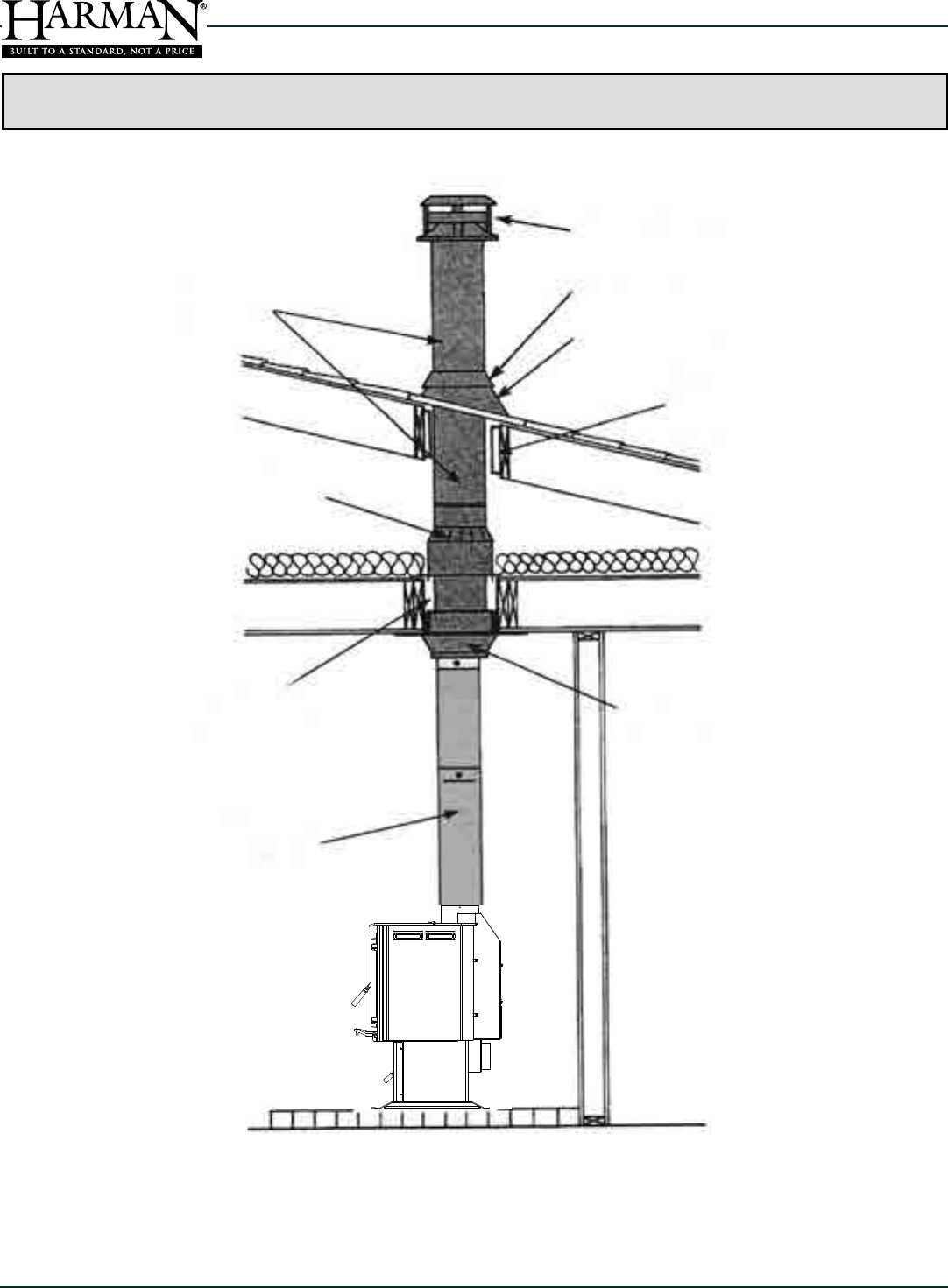
Standard Ceiling Installation with Factory Built Chimney
The Chimney Connector Shall Not Pass Through an Attic or Roof
Space, Closet or Similar Concealed Space, a Floor or Ceiling.
Chimney Cap
Storm Collar
Chimney
Sections
Minimum Air Space
with Chimney
Listing
Chimney
Connector
Chimney
Support
Roof Flashing
Roof
Radiation
Shield
Attic
Radiation
Shield
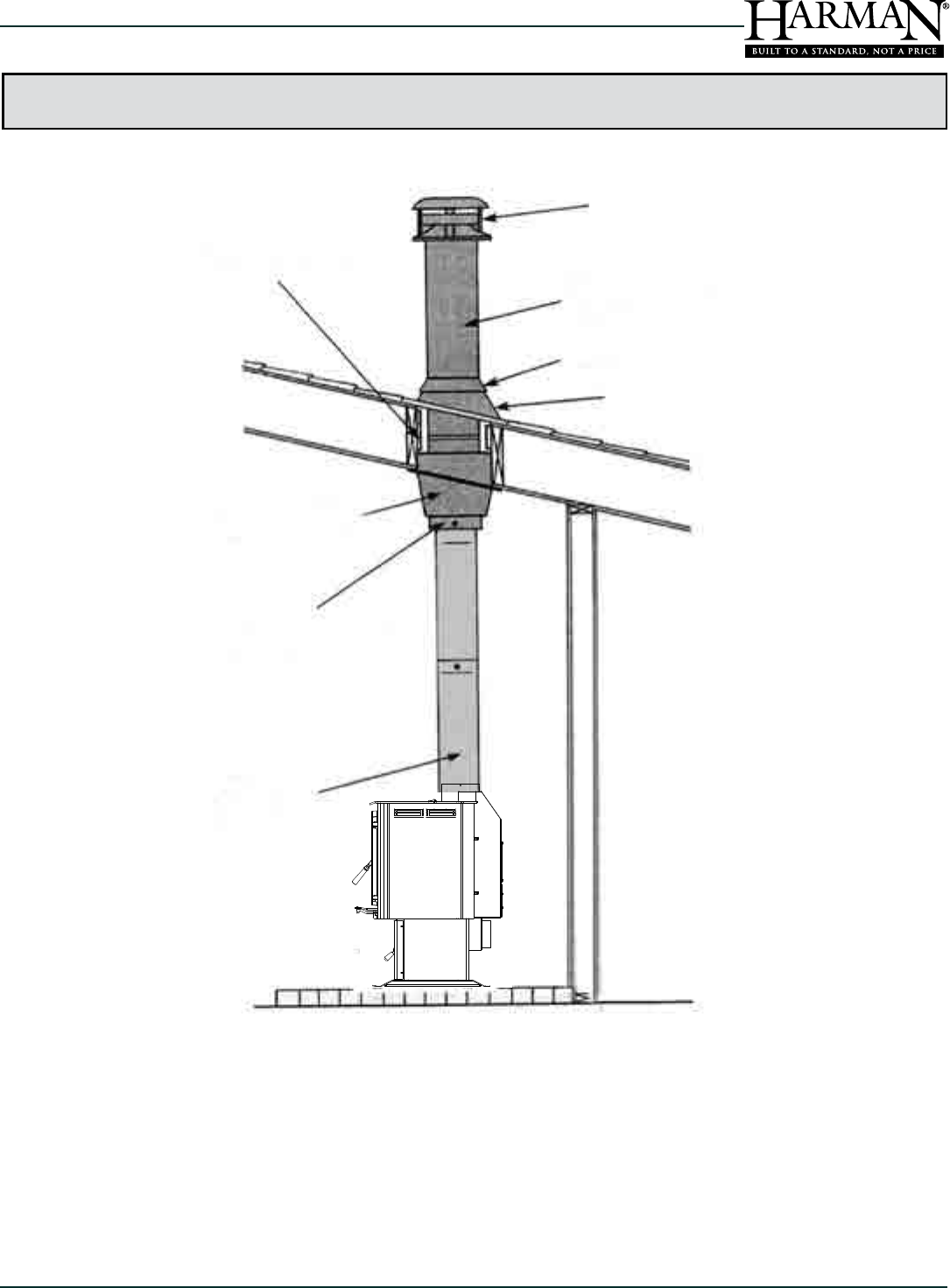
17
Dry Seasoned Wood Only!
TL2.0 Woodburning Stove
Save These Instructions 3-90-08560
Roof Flashing
Chimney Cap
Factory-Built
Metal Chimney
Sealed Storm Collar
Finishing
Collar
Chimney
Connector
Roof Radiation
Shield
Cathedral Style
Chimney Support
Cathedral Ceiling Installation with Factory Built Chimney
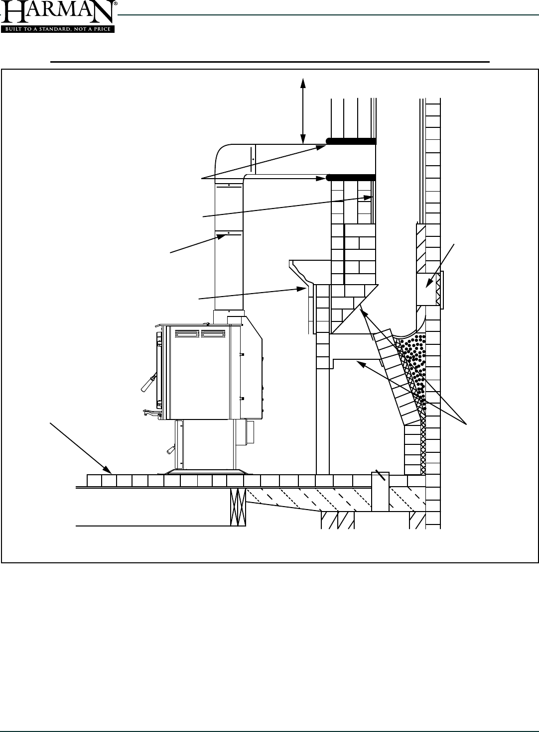
18
TL2.0 Woodburning Stove
Dry Seasoned Wood Only! Save These Instructions3-90-08560
The Chimney Connector Shall Not Pass Through an Attic or Roof Space, Closet or Similar Concealed Space, a
Floor or Ceiling.
Minimum clearance to
unprotected ceiling 15”
Chimney connector
sealed at thimble
Flue liner with required air space
Minimum of three sheet
metal screws per joint of
chimney connector
Mantel and trim protection
Airtight
insulated
clean-out
Damper closed
and sealed with
non-combustible
material
Combustible Floor
Floor Protection*
*Floor protection in accordance with Solid Fuel Appliance Listing
19
Dry Seasoned Wood Only!
TL2.0 Woodburning Stove
Save These Instructions 3-90-08560
* Floor Protection in Accordance with Solid Fuel Appliance Listing
The Chimney Connector Shall Not Pass Through an Attic or Roof Space, Closet or Similar Concealed Space, a
Floor or Ceiling.
Minimum clearance from chimney
connector to uprotected ceiling 15”
Flue liner with required
air space
Listed or approved thimble assembly
1” Clearance for exterior chimney or
2” clearance for interior chimney and
2” clearance for NFPA 211 - type
approved thimbles
Airtight
insulated
clean-out
Damper closed
and sealed with
non-combustible
material
Combustible Floor
Floor Protection*
* Floor protection in accordance with Solid Fuel Appliance Listing
** Check with your local building codes inspector for clearance.
Combustible
Wall
Sheet
Rock
Mantel and Trim Protection
20
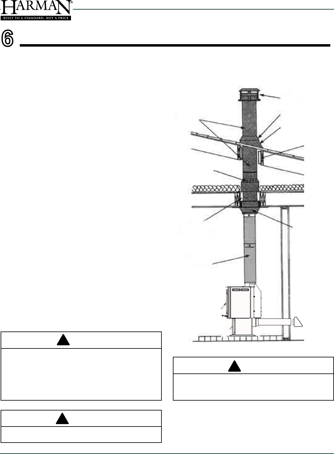
TL2.0 Woodburning Stove
Dry Seasoned Wood Only! Save These Instructions3-90-08560
DO NOT INSTALL IN A MOBILE HOME IN CANADA.
1. An outside air inlet must be provided for combustion
air, and must remain clear of leaves, debris, ice, and/or
snow. The outside air path must be unrestricted while
the appliance is in operation. Use Kit #1-10-856082 to
attach to unit.
2. The combustion air intake system must be of metal
construction. It must permit zero-clearance to
combustible materials, and contain a rodent screen.
3. The appliance must be secured to the mobile home
structure by bolting it to the oor. There are holes
provided in the pedestal base. Secure with the proper
length lag bolts, through the hearth pad and into the
home oor.
4. The appliance must be grounded to the metal framing
of the mobile home
5. All clearances to combustibles and oor protection
requirements must be followed.
6. Follow the vent manufacturer's instructions when
installing in a mobile home. Must be connected to a
UL103 HT ventillated chimney connector, UL103 HT
chimney, and terminal cap with spark arrestor.
7. Use silicone to create an effective vapor barrier at
the location where the chimney or other component
penetrates to the exterior.
8. Installation shall be in accordance with the Manufactured
Home and Safety Standard (HUD) CFR 3280, Part 24
9. The appliance must never be installed in a room
designated for sleeping.
10. Burn wood only. Other fuels may generate poisonous
gases (carbon monoxide).
11. If unit burns poorly while an exhaust blower (range
hood) is operating, increase the supply of combustion
air to the appliance
NOTE: The top sections of the chimney must be removable
to allow a maximum clearance of 13.5 feet (411cm) from
ground level for transportation purposes.
Chimney Cap
Storm Collar
Chimney
Sections
Minimum Air Space
with Chimney Listing
Chimney
Connector
Chimney
Support
Roof Flashing
Roof
Radiation
Shield
Attic
Radiation
Shield
Outside
Air
6
THE STRUCTURAL INTEGRITY OF THE MOBILE HOME
FLOOR, WALL AND CEILING/ROOF MUST BE MAINTAINED.
DO NOT CUT THROUGH:
FLOOR JOIST, WALL STUDS, OR CEILING TRUSSES.
ANY SUPPORTING MATERIAL THAT WOULD AFFECT
THE STRUCTURAL INTEGRITY.
CAUTION
!
INSTALLATION MUST COMPLY WITH
MANUFACTURED HOME AND SAFETY STANDARD
WARNING
!
DO NOT INSTALL IN SLEEPING ROOM.
WARNING
!
21
Dry Seasoned Wood Only!
TL2.0 Woodburning Stove
Save These Instructions 3-90-08560
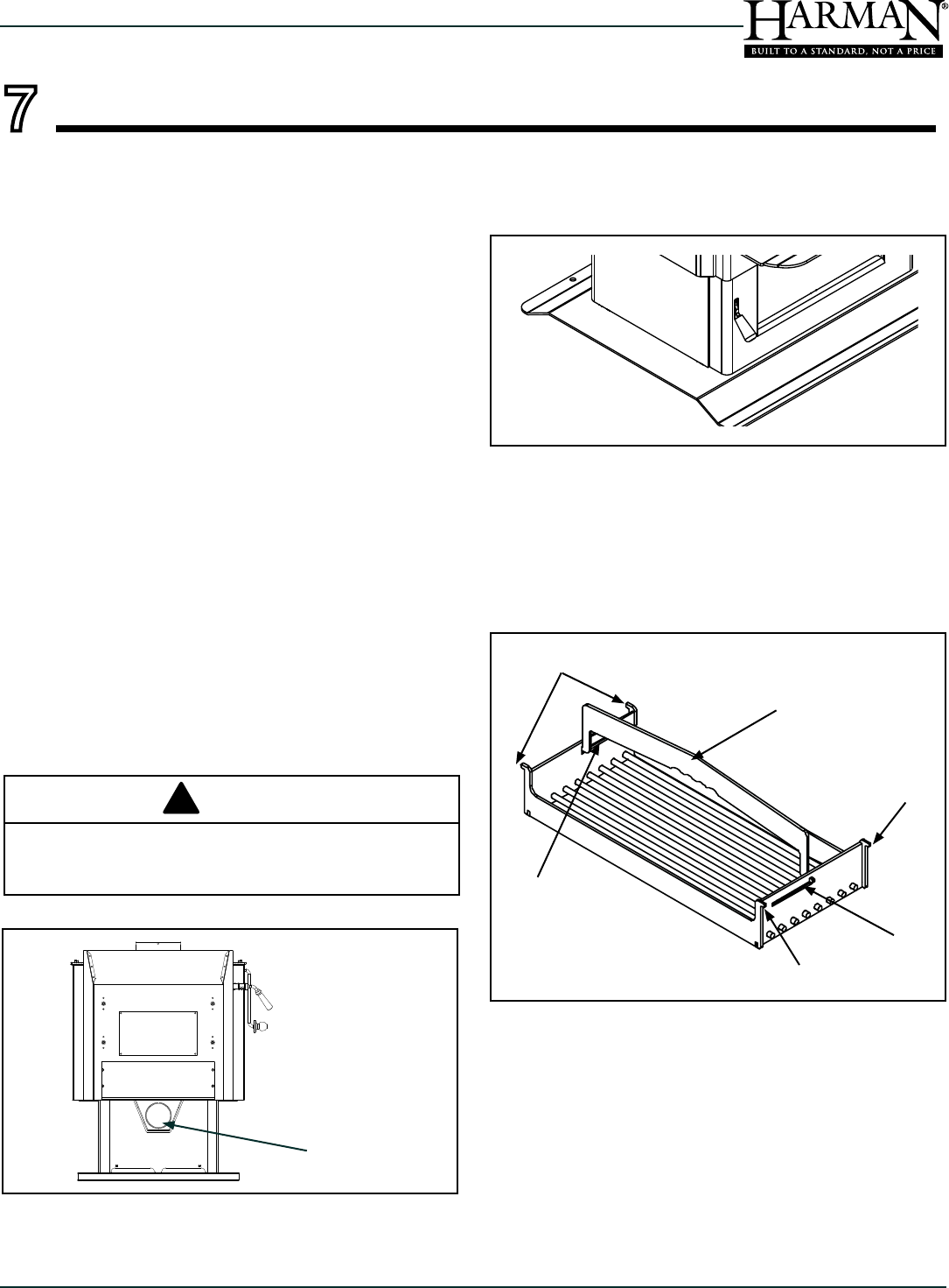
A. Outside Air Attachment
Parts and Supplies Needed: Kit #1-10-856082, 1 piece of
metal exible pipe, 4" X needed length. 1 Rodent Screen,
and aluminum tape. Plus, a trim ring for nishing around the
pipe on the inside wall.
1. Determine an appropriate hole location, through the
wall. Be sure there are no studs or other supporting
members. Also ensure there are no electrical wires or
plumbing contained within the wall.
2. Make the hole through the exterior wall using a hole
saw or reciprocating saw. You'll want the hole to be just
slightly larger than the metal ex pipe.
3. Attach the rodent screen to one end of the ex pipe,
and insert it through the wall until the back of the screen
cover is against the outside surface.
4. Hold the ex pipe in place to make an accurate
determination of the length needed. Cut the ex pipe
to length.
5. Slide the trim ring onto the ex for the inside wall portion.
6. Slide the other end of the metal intake ex pipe into
the stub on the rear of the stove and secure it with
aluminum tape. This air intake will supply outside air for
the secondary combustion.
7. Secure the trim ring in place for nishing the inside wall
area.
8. Seal around the rodent screen on the exterior wall,
using silicone caulking.
B. Leveling the Appliance
Use metal shim material under the pedestal base where
needed for leveling.
C. Optional Cooking Grill
The optional cooking grill #1-00-08121 installs easily in the
top load opening of the stove.
The grill handle (B) ts in the slots (C) on each side. To
remove the handle, lower and turn.
When installed, the grill hangs in the opening by the hooks
(A).
When grilling, you'll want to keep the re size small and
the bypass damper in the open position. Depending on the
grilling being done, you may get grease dripping on the
glass causing it to become dirty and obstructed. When you
burn your next hot re, the glass will likely clean itself.
LOADING OR UNLOADING GRILL.
7 Appliance Set-Up
NEVER DRAW OUTSIDE COMBUSTION AIR FROM:
WALL, FLOOR OR CEILING CAVITY.
ENCLOSED SPACE SUCH AS AN ATTIC OR GARAGE
CAUTION
!
A
A
A
B
C
C
Outside Air
Attachment
22
TL2.0 Woodburning Stove
Dry Seasoned Wood Only! Save These Instructions3-90-08560
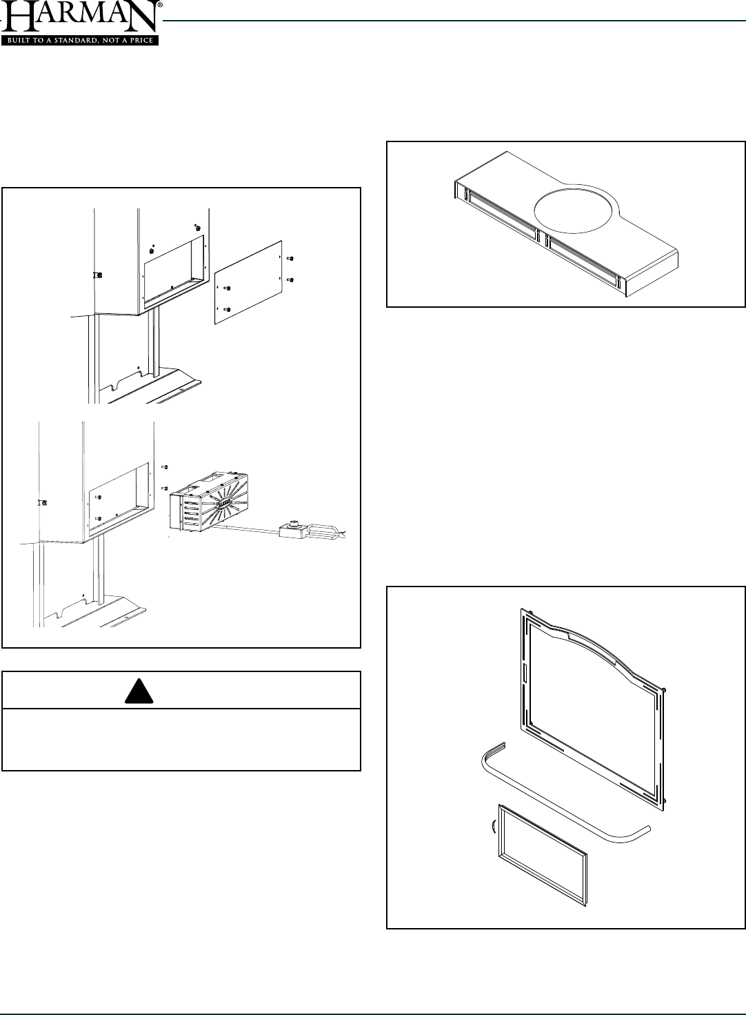
D. Optional Blower Installation
Use ONLY Blower Part #1-00-856002 With This
Appliance.
The optional blower kit installs easily to the rear of the TL2.0.
First, remove the air jacket shield from the rear of the stove.
Use the same four bolts to attach the blower as shown.
E. Top Air Grill Option
The top air grill installs over the ue collar and simply
rests on the top of the stove. The brushed stainless grill is
included with this option as well.
F. Brushed Stainless Trim Kit Option
The trim kit consists of three pieces; Load door trim, Ash lip
trim, and the Ash door frame. To install the load door trim, it
is best to remove the door by lifting from the hinges. lay the
door down at on it's face. Drill the dimpled holes in each
corner of the door and re-install the door onto the stove.
From the outside, install the frame with the studs going
through the newly drilled holes and install the nuts on the
inside. To install the ash lip trim, just slide it onto the ash lip.
You may attach with silicone if desired. The ash door frame
uses a spring clip on one end to hold it into the recessed
area of the ash door. Install the clip in the frame channel
and push that end into the door opening until the other end
of the frame ts.
Plug the blower into a properly grounded electrical outlet.
Keep the blower on low speed or off during low res. As
you get out of the low burn range, the speed can be set
wherever desired, or kept off.
ROUTE POWER CORD AWAY FROM THE APPLIANCE.
DO NOT RUN THE CORD UNDER OR IN FRONT OF
THE APPLIANCE.
WARNING
!
23
Dry Seasoned Wood Only!
TL2.0 Woodburning Stove
Save These Instructions 3-90-08560
Select only dry, seasoned wood. Wood for burning should
never be exposed to rain or extremely damp conditions.
Hardwoods are favored because they are heavier and contain
more heating capacity (BTU’s) per load than do softwoods.
Fuel wood should be split and stored under cover for
“seasoning” - at least a year is recommended. Your stove is
not an incinerator - do not burn garbage, painted or treated
wood, plastic, or other debris.
Keep the area around the stove free from clutter. Keep
all combustibles, including fuel, beyond the code-required
clearance distance (48" or 1215 mm in the U.S., 1525 mm or
60" in Canada). Never store fuel in front of the stove where
it could interfere with door operation, safe loading, and ash
removal.
B. General Operating Information
1. Draft Before you install and/or operate your wood stove, please
read the entire contents of this manual. Pay particular attention
to the explanation of draft and its effect on stove performance in
the Installation section. By following the installation and
operating guidelines, you will ensure proper draft and gain
maximum efciency and enjoyment from your stove.
DO NOT ALTER THE POSITION OF THE ANDIRONS.
BUILDING A FIRE TOO CLOSE TO THE GLASS MAY
CAUSE DAMAGE TO THE GLASS, CREATING A SERIOUS
RISK OF FIRE AND PROPERTY DAMAGE.
2. Doors Your stove has a large glass-paneled door for
loading and re viewing, a separate smaller door for removing
ashes and a top loading door.
Front Door
Before opening, always check for wood, embers, or ash that
may be ready to fall out of the door.
To open the glass door, open the bypass damper rst, then
turn the handle clockwise and pull out; to close the door,
push the door closed with the handle in the open position,
then turn, counter-clockwise, to engage the latch.
Ash Door
To open the ash door, lift up the handle and pull out. Close the
door by pushing in and pushing the handle all the way down.
Top Load Door
To open the top load door, open the bypass damper and then
lift to open the top load door.
All doors must be closed while the stove is in normal
operation, and the gaskets routinely examined for wear and
replaced when necessary. Good door seals are important
for maintaining control of the stove. Never operate with the
ash door open. Operating the stove with the ash door open,
or with a door inadequately sealed, could create a serious
overring condition (discussed later in this section).
The glass used in your stove is manufactured to exact
standards to withstand the high heat of the re, but like all
glass, it must be treated with common sense and care. Never
abuse the glass by slamming the door shut or striking the
glass with a heavy object. If the glass is broken or damaged,
do not operate the stove until it has been replaced
(See instructions in the Maintenance section.)
8 Operating Instructions
"NEVER USE GASOLINE, GASOLINE-TYPE LANTERN
FUEL, KEROSENE, CHARCOAL LIGHTER FLUID, OR
SIMILAR LIQUIDS TO START OR "FRESHEN UP " A
FIRE IN THIS HEATER. KEEP ALL SUCH LIQUIDS
WELL AWAY FROM THE HEATER / FIREPLACE STOVE
WHILE IT IS IN USE".
WARNING
!
CAUTION
!
Approved for use with wood fuel only. The use of any
other fuel will void the product warranty and may
cause damage to the appliance and/or your home.
CAUTION
!
ALWAYS WEAR FIRE RETARDANT GLOVES WHEN
OPERATING THE STOVE.
SAFETY NOTICE
IF THIS APPLIANCE IS NOT PROPERLY INSTALLED,
OPERATED AND MAINTAINED, A HOUSE FIRE MAY
RESULT. FOR YOUR SAFETY, FOLLOW INSTALLATION
DIRECTIONS. CONTACT LOCAL BUILDING OR
FIRE OFFICIALS ABOUT RESTRICTIONS AND
INSTALLATION INSPECTION REQUIREMENTS IN
YOUR AREA.
DO NOT BURN GARBAGE OR FLAMMABLE LIQUIDS
SUCH AS GASOLINE, NAPTHA, OR ENGINE OIL.
24
TL2.0 Woodburning Stove
Dry Seasoned Wood Only! Save These Instructions3-90-08560
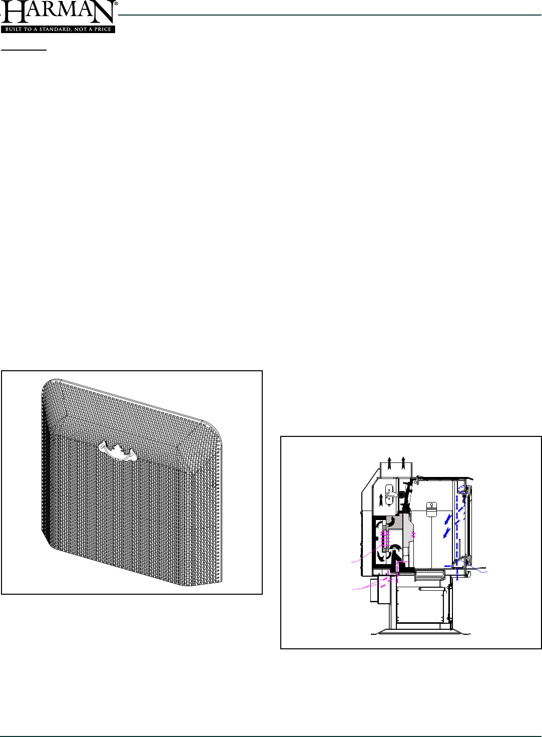
Combustion in the rebox is precisely controlled and is best
explained in two parts.
During a wood re, combustion air enters at the bottom
front of the stove where it travels upward through channels
at either side of the front door. From the manifold located
above the front door, it is directed into the rebox as a sheet
of air owing between the glass and the wood. This concept
helps to keep the glass clean, while providing the oxygen
needed to sustain burning. This is what is known as "Primary
Combustion".
Additional air enters at the bottom rear of the stove body.
Some of this air enters through holes in the rear bricks where
it is used to revitalize the re at the rear of the rebox. The
remainder is delivered into the "Firedome Plus" combustion
package where the "Secondary Combustion", or re-burning
of the smoke, occurs.
During combustion, the burning of wood proceeds through
several stages. The initial or evaporation stage is where
the moisture in the wood is driven off in the form of steam.
A second stage is where the volatile gases contained in the
wood are released and burned. This represents most of the
wood's heating capacity. The nal stage is the charcoal stage
where the charcoal burns the remaining heat content in the
wood fuel. Ash remains after the burning is complete. Within
the primary rebox two or more of these stages of combustion
are occurring at once.
Always be sure to provide adequate ventillation to the room
where the apliance is located, to prevent air starvation. In tight
construction, consider installing outside air to the appliance.
3. Grates
The unique grate system consists of one at bottom grate,
and two front andirons. The bottom grate has slots which
allow the ash to fall into the ash pan by passing a poker back
and forth across the grate. The andirons keep the fuel from
coming into direct contact with the glass, and keep hot coals
and embers from spilling out while reloading. Never build a
re directly against the glass.
The grates and andirons must remain in place at all
of this grate system.
C. Burning as a Fireplace
This appliance has been tested and approved for burning as
an open replace. To do so, a spark screen (Harman part#
3-40-06960; Cozy Screen) must be installed over the front
door opening. The by-pass damper must be kept in the open
position.
The Cozy Screen can be used from the start of a re or can
be used with an existing one. When starting a re with the
Cozy Screen, smoke spillage may occur until it develops a
draft strong enough to pull all smoke back into the ue.
DO NOT LEAVE THE APPLIANCE UNATTENDED WITH
THE DOOR OPEN!
Load only small amounts of wood at a time.
SECONDARY AIR FLOW
SECONDARY AIR ENTERING
EXHAUST STREAM
SECONDARY AIR
THRU BRICK
EXHAUST STREAM
PRIMARY AIR FLOW
25
Dry Seasoned Wood Only!
TL2.0 Woodburning Stove
Save These Instructions 3-90-08560
For low burn, slide the air control to the left. For medium
burns, use notches 1 to 2. Maximum heat is attained with
the air control all the way to the right. Do not burn the stove
continuously at the maximum setting. If maximum heat is
required day after day, the stove is too small for the area
you are trying to heat.
If your wood is not seasoned long enough or is high in
moisture content, you may need to adjust the primary air
slightly higher to sustain a low burn rate with the cleanest
possible exhaust.
F. Before Your First Fire
• Be sure the appliance is installed properly and that
all safety requirements have been met. Pay particular
attention to the clearances to combustibles, oor
protection and the venting instructions.
• Test your smoke detector(s) and CO detector(s) to the
specications of the manufacturer.
• Double check that the ash pan and internal rebox are
empty.
• Be sure to read this entire manual.
Begin with the bypass damper open, and the air control lever
at the maximum setting, all the way to the right. Be sure the
ash pan door is closed and latched.
Start with a bed of crumpled paper and kindling sized about
nger width; place several 1" - 2" (25mm - 50mm) split pieces
of dry wood on top of the kindling, followed by a few 2" - 3" (50
mm - 80 mm) split pieces. Lay the wood in a crossed pattern to
allow maximum air ow. Ignite the paper and close the loading
door(s). Allow this start-up re to burn for a few minutes,
keeping the bypass damper open. Add about ve more pieces
of wood in the 2 to 3 inch (50 - 80mm) size range, making
sure that the fuel bed is all the way across the rebox and
staggered to allow airow. Close the door and allow this
loading to burn a few minutes.
Add increasingly larger pieces of wood to the re until you
have a thick bed of hot embers, approximately 2 to 3 inches
deep at the back of the grate and at least an inch deep at the
front. You must have this charcoal bed established before
you close the bypass damper.
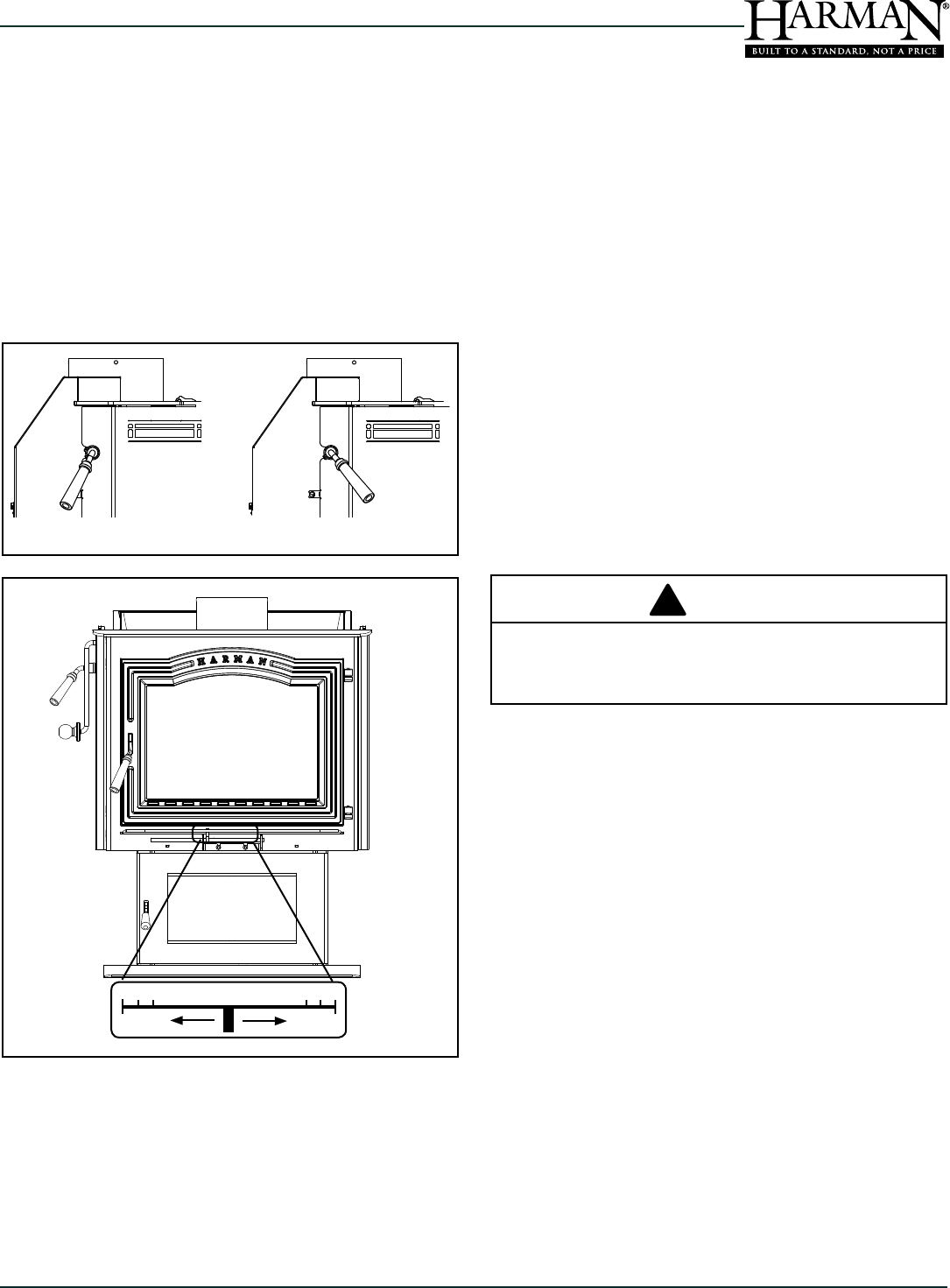
E. User Controls
Two important controls - the damper bypass handle and the
air control lever regulate the operation and output of the stove.
To open the top or front loading door, you must open the
damper bypass, or smoke will come in the room. In this
mode of operation the combustion gases go directly from
the main combustion chamber to the ue collar and exit into
the chimney.
loading. Open the bypass damper by turning the handle
clockwise while facing handle.
The air control lever is located on the ash lip, below the load
door. Sliding this lever allows you to vary the amount of air
to the re, creating a range of heat outputs. The lowest heat
output setting is to the left, and the highest is to the right.
The notches are provided as a reference for your comfortable
heat settings. Do not, under any circumstances, alter the
conguration or operation of the air control lever.
Damper Open Damper Closed
Minimum
Primary Air
Maximum
Primary Air
DO NOT OVERLOAD THE APPLIANCE. IF YOU
CAN NOT CLOSE THE LID OR DOOR, YOU HAVE
OVERLOADED.
CAUTION
!
26
TL2.0 Woodburning Stove
Dry Seasoned Wood Only! Save These Instructions3-90-08560
Providing you have the charcoal bed described, close the
bypass damper by pulling the handle toward the front of the
stove. This will begin the highly efcient mode of operation
where the exhaust gases get re-burned in the secondary
combustion package. If you cannot achieve a charcoal bed
within the rst 15 to 20 minutes, your wood is likely too wet,
and you may need to burn the re longer and/or hotter to
compensate for the extra energy needed to drive out the
moisture. If, after ve minutes of burning with the damper
closed, smoke is visible coming from the chimney, you
probably do not have the proper coal bed. Open the bypass
damper and continue with the process until a signicant coal
bed is formed.
Always remember to open the bypass damper when you are
loading, this allows the exhaust gases to pass directly into
the ue outlet and reduces the chance of smoke spillage
into the room.
Reloading: Once you have prepared and maintained a thick
charcoal bed, and the secondary combustion is established,
you should be able to reload the stove at any time by simply
opening the bypass damper, then the load door, adding fuel
and closing the door then the damper. This depends on coal
bed size, load size and moisture content of fuel.
Removing Ashes: Before reloading, empty the ash pan
(remember to close the ash door while emptying the pan).
The ashes should be the coolest at this time. Remove ashes
from the re chamber periodically by raking a poker across
the bottom grates.
Excessive ash buildup can prevent proper venting of exhaust
gases. Do not allow the ash pan to over-ll. Ash buildup
between the ash pan and the bottom of the grate can cause
the grate to overheat and wear out prematurely.
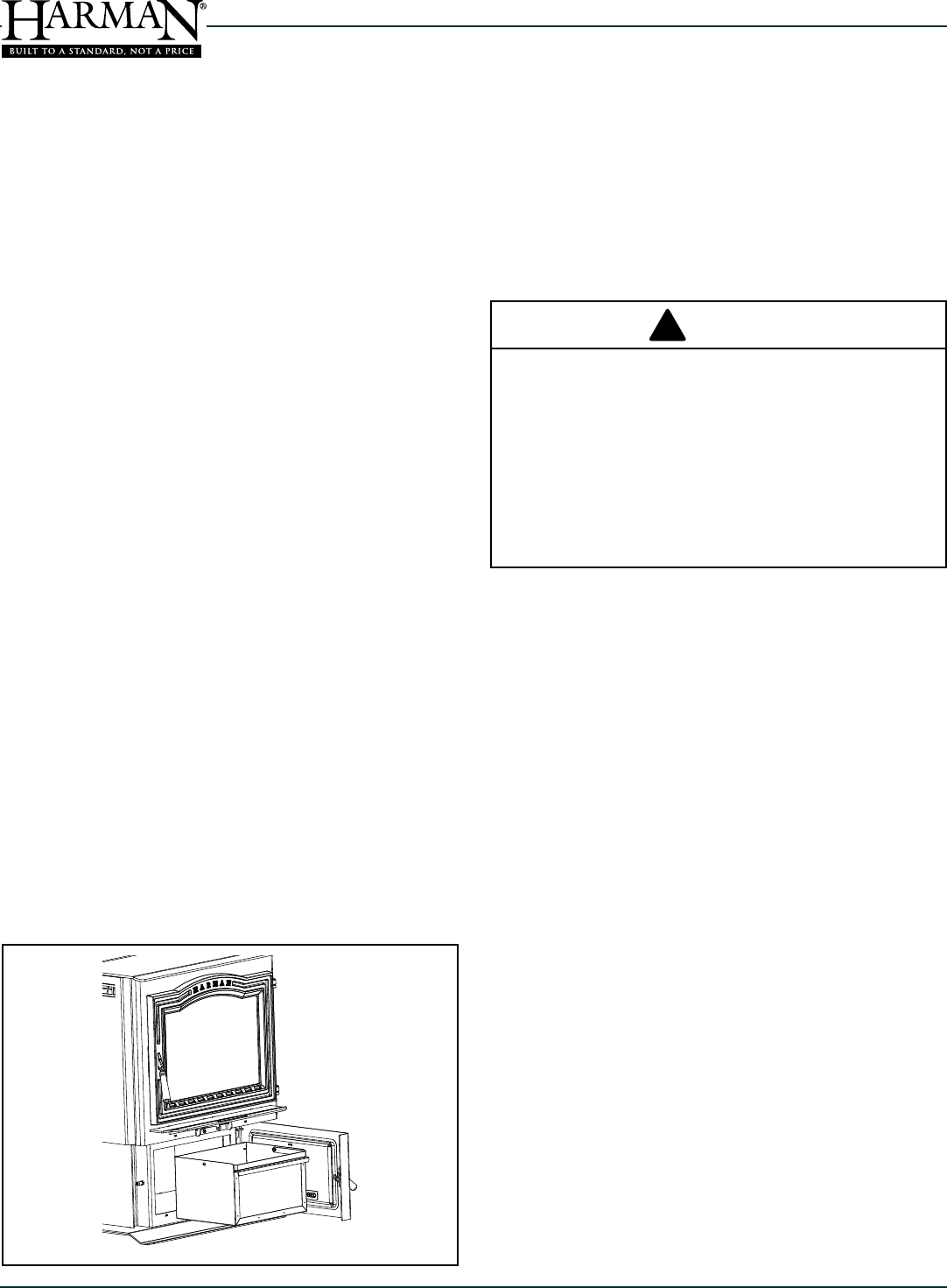
The TL2.0 is designed to provide access to the ash pan
without the need for opening the main door. Before opening
the ash door and removing the ash pan, open the bypass
damper. Wearing heavy protective gloves, open the ash door
and remove the ash pan by pulling it forward by the handle.
Close the ash door and damper bypass before taking the
ashes outside for safe disposal.
Avoid overfiring your stove. Overfiring is a potentially
hazardous situation which can lead to overheating of
combustible materials nearby, damage to the stove, and
in extreme cases, cause a re. Overring is caused by: 1.
Too much air owing through the stove too quickly. 2. You
may have positioned the primary air control lever too far to
the right. 3. Inadvertently leaving the damper open or 4. Not
keeping up with routine maintenance, such as checking door
gaskets for wear.
Overring results in excessive fuel consumption, and may
cause parts of the stove or chimney connector to glow red.
If you notice signs of overring, reduce the air supply to the
re, and review the Maintenance section in this manual.
In the event of a chimney re, call your local re department;
make sure everyone is safely out of the house. Reduce the
air intake of the stove as much as possible using the air
control lever; close the bypass damper to further restrict air
ow. Do not throw water on the re; this can cause stove
damage and create an even more dangerous situation. Have
your chimney professionally cleaned and inspected before
resuming burning in your stove.
As you begin to operate your stove at higher temperatures,
you will notice a “hot” or unpleasant smell; this is just the
paint going through the curing process, and will disappear
after a few res.
DISPOSAL OF ASHES;
a tight fitting lid. The container of ashes should
container until all cinders have completely cooled. Other
HOT WHILE IN OPERATION. KEEP CHILDREN,
CLOTHING AND FURNITURE AWAY. CONTACT MAY
CAUSE SKIN BURNS.
NEVER LEAVE THE STOVE UNATTENDED IF EITHER
THE ASH OR LOAD DOOR IS OPEN. OVERFIRING
MAY RESULT.
DOOR CLOSED DURING FIRING OF THE HEATER.
CAUTION
!
27
Dry Seasoned Wood Only!
TL2.0 Woodburning Stove
Save These Instructions 3-90-08560
9 Service & Maintenance
A. Creosote- Formation and Need For Removal;
When wood is burned slowly, it produces tar and other
organic vapors which combine with expelled moisture
to form creosote. The creosote vapors condense in the
relatively cool chimney ue of a slow burning re. As a
result, creosote residue accumulates on the ue lining.
When ignited, this creosote makes an extremely hot re.
The chimney and chimney connector should be inspected
at least once every two months during the heating season
to determine if a creosote buildup has occurred. If creosote
has accumulated, 3mm or more, it should be removed to
reduce the risk of a chimney re.
Close the air control
and bypass damper and notify the re department. Do NOT
apply water to the re, in the rebox or in the chimney. Do not
operate the appliance until the chimney and connector have
been inspected and approved by a chimney professional.
Do not burn any fuel other than wood, such as charcoal,
which can cause increased carbon monoxide production or
overring. Never use highly volatile substances in your stove,
such as gasoline, which could cause an explosion.
When solid fuels are burned completely, they produce
water and carbon dioxide. However, in long slow burns, a
substantial amount of carbon monoxide may be produced.
If allowed to build up, carbon monoxide (which is odorless)
can prove fatally poisonous. Proper ventilation and draft will
prevent this from happening. If you smell smoke, turn up
the air control lever setting, and thoroughly ventilate your
dwelling. During future burns, be careful not to overload
the stove with fuel, so you will not be tempted to constantly
operate at a low air control setting.
Other causes of poor ventilation or draft are icing, exhaust
fans, a blocked outside air inlet, and room air starvation. If
your stove is sluggish and you get occasional odor, check
these possibilities and increase the air ow in your home.
as soot, ash and creosote may accumulate.
ALWAYS WEAR FIRE-RESISTANT GLOVES TO
OPERATE THE STOVE. THE AIR CONTROL IS HOT
WHILE IN OPERATION.
CAUTION
!
When properly maintained, your stove will give you many
years of trouble-free service. Contact your dealer to answer
questions regarding proper operation, trouble-shooting and
service for your appliance. Visit www.harmanstoves.com to
nd a dealer. We recommend annual service by a qualied
service technician.
Seasonal cleaning
At least once per year, the stove, venting connectors and
chimney should be thoroughly cleaned. If the areas are
found to have an excessive build up of ash or creosote, it
is recommended to increase the frequency of the cleaning.
This will extend the life of the appliance and its components.
A vacuum specically designed for ash is preferred, however
a standard shop-style vacuum with a HEPA lter may also
work just ne.
During cleaning, caution must be taken not to damage the
white / gray colored ceramic combustion package in the rear
of the rebox. When using a brush in the chimney or venting
connector, the by-pass damper should be placed in the open
position to help prevent ash, creosote or other debris from
falling down onto and around the combustion package. This
also protects the top of the combustion package from tool
or brush damage and diverts most of the removed materials
into the rebox for easy clean-up and removal. Once the
venting system has been cleaned, remove the rst section
of connector pipe from the appliance ue collar. Carefully
vacuum the ash and debris from around the sides and top
of the combustion package.
The shoe brick must be removed to allow vacuum access for
cleaning the front portion of the combustion package.
Always use caution when refueling or when vacuuming the
rebox and combustion package. Some users have damaged
their combustion package with vacuum cleaner tools, and
re pokers.
28
TL2.0 Woodburning Stove
Dry Seasoned Wood Only! Save These Instructions3-90-08560
B. General Maintenance Procedures
1. Ash Removal
Frequency: As needed / Every day or two
By: User
Wear Leather Gloves To Prevent Skin Burns!
Open the ash removal door by lifting upward on the latch
handle, then swing the door open. Pull the ash pan out of
the rebox, using the lip on the front of the pan. Once the
ash pan is removed from the stove, you can ip the carry
handle up for convenience.
If removing ashes while a re is burning, close and latch the
ash door while disposing of the ashes.
DO NOT leave the appliance unattended with the ash door
open.
2. Door Glass
Frequency: As needed / Weekly
By: User
Whenever the view of the re is obstructed, or weekly,
clean the glass using a soft cloth dampened with standard
household glass cleaner.
DISPOSAL OF ASHES;
a tight fitting lid. The container of ashes should
container until all cinders have completely cooled. Other
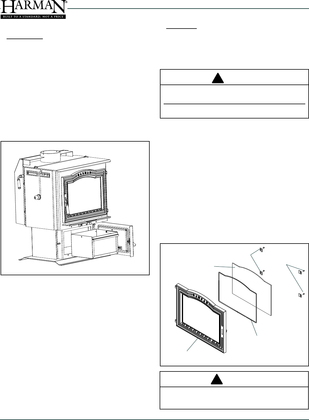
Glass Retainer
screws
Glass Panel
Glass Gasket
Glass Retainers
Door Frame
CAUTION
!
DO NOT CLEAN GLASS WHEN HOT. Allow glass to
Fly-ash allowed to accumulate on the glass may lead to
Inspect the glass and sealing gasket. Replace gasket as
needed. Do not operate the stove with a broken glass.
Replacement glass, which is ceramic glass, should be
obtained only through your Harman dealer.
To replace a broken glass; rst be sure to carefully remove
the broken glass and any remaining shards or pieces. With
the door laying on a at surface, lay the gasketted glass
panel onto the door and be sure it is properly tted into the
channel. Lay the glass retainer clips in place near each
corner, and secure them using the 3/8" screws. Be sure to
tighten each screw equally so you don't create a pressure
point on the glass.
Replacement.
NEVER USE ABRASIVE MATERIALS ON THE GLASS.
WARNING
!
DO NOT ABUSE GLASS BY STRIKING OR SLAMMING
THE DOOR CLOSED. THIS TYPE OF BREAKAGE IS
NOT COVERED BY THE PRODUCT WARRANTY.
29
Dry Seasoned Wood Only!
TL2.0 Woodburning Stove
Save These Instructions 3-90-08560
3.
Frequency: As necessary / Yearly
By: User
Cleaning the rebox and internal heat exchange surfaces is
recommended to maintain thermal efciency. Depending on
the quality and quantity of fuel being used, you may want to
perform this cleaning monthly.
Be sure to clean these areas thoroughly at the end of the
heating season.
Brush and vacuum all internal surfaces at the end of the
heating season. Ashes will draw moisture and may promote
rust formation.
4. Blower- If installed
Frequency: As necessary / Yearly
By: User
The fan on the blower will collect pet hair and other debris
over time. Any accumulation must be removed to maintain
proper operation.
To clean blower;
Disconnect Power Cord Before Servicing.
• Remove the four bolts that hold the blower in place.
• You will nd it easiest to use an air hose and blow the
debris from the blower housing.
• Alternately, with some minor disassembly, you can use
a vacuum and/or brush to clean the blower wheel.
• Reinstall the blower and tighten the four bolts securely.
5. Chimney Connector
Frequency: As necessary / Yearly
By: Qualied Service Technician / User
At the end of the burn season, brush and clean all sections
of chimney connector pipe. Some owners remove the
chimney connector for the off season. Any ashes left in the
connector pipe will actually draw moisture which promotes
rust. This is why it is very important to clean all ashes at the
end of the heating season.
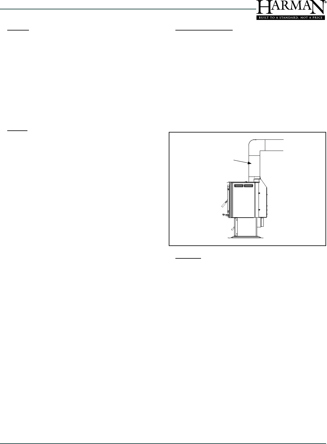
When cleaning the chimney connector above the appliance,
keep the bypass damper in the open position. This will keep
any loosened material from falling into the Firedome Plus
combustion chamber.
6. Chimney
Frequency: As necessary / Yearly
By: Qualied Service Technician / Chimney Sweep
The entire chimney should be professionally cleaned at
least once yearly. It is best to have this done at the end of
the heating season to be sure all ash is removed. You'll also
want to inspect the condition of the chimney prior to using
the appliance, to be sure there are no bird or animal nests.
Chimney
Connector
30
TL2.0 Woodburning Stove
Dry Seasoned Wood Only! Save These Instructions3-90-08560
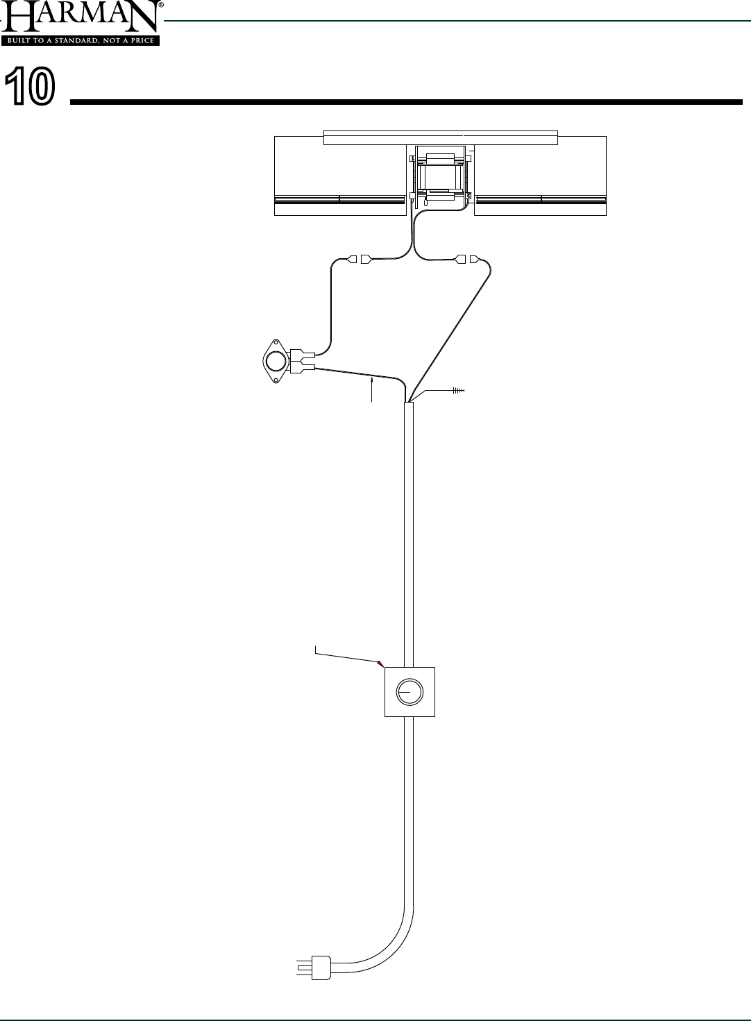
Variable Speed Switch
Power Cord
Blower Thermostat
Grounded to housing
Black
Wire
White
Wire
2
1
TL2.0 / TL2.6 Optional Blower Kit #1-00-856002 - WIRING DIAGRAM
10 Reference Materials
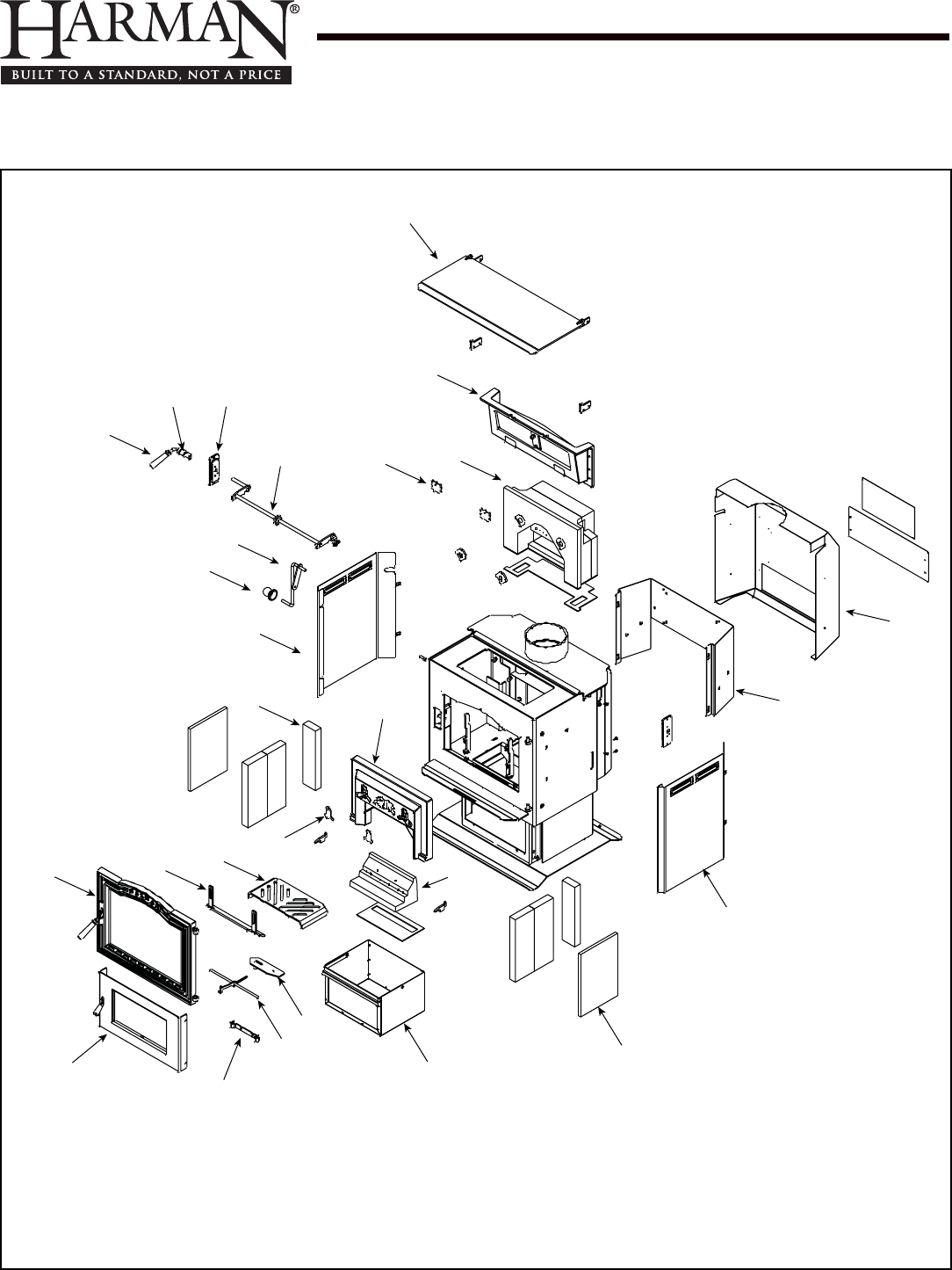
Service Parts TL2.0
Beginning Manufacturing Date: Sept 2011
Ending Manufacturing Date: Active
Wood Stove
1-90-856000-1 Black W/Pedestal
2
3
1
4
67
8
9
10
11
14 12
15
13
16
17
18
19
20
21
22
23
24
25
5
27
26
11/13
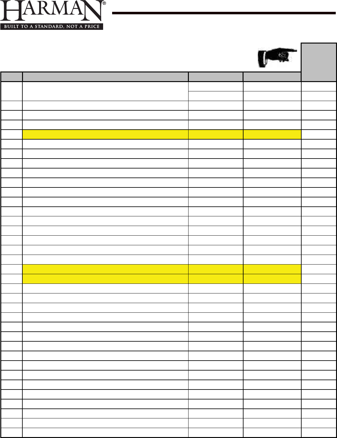
Service Parts TL2.0
Beginning Manufacturing Date: Sept 2011
Ending Manufacturing Date: Active
IMPORTANT: THIS IS DATED INFORMATION. Parts must be ordered from a dealer or
distributor. Hearth and Home Technologies does not sell directly to consumers. Provide
model number and serial number when requesting service parts from your dealer or distributor.
Stocked
at Depot
ITEM DESCRIPTION COMMENTS PART NUMBER
1 Top load door, painted w/gasket & hdwr Pre 008840369 1-10-856509A
Post 008840369 1-10-856009A Y
Bottom Hinge Set of 2 1-00-856084
Hinge spacer Qty 2 req 2-00-40021L
Top load door gasket 5 ft 1-00-10050 Y
Wood Handle, Pkg of 3 Pre 008840369 3-40-08746-3
2Damper frame asy with damper 1-10-250109A Y
Damper adjuster with hardware 1-00-250153
Damper gasket 30 ft 1-00-00888 Y
Damper Only 1-10-249107
Damper Shaft Retainer & Hardware Set of 2 1-00-249145 Y
Gasket, 1" Single Ply Tape 10 Ft 1-00-88100 Y
3Firedome Plus Combustion Package 3-40-358110 Y
Gasket, brick air Pkg of 4 3-44-2500202-4 Y
4Rear brick clips with hardware Pkg of 2 1-00-249135
5Wooden handle for damper w/hardware Pkg of 2 1-00-00249 Y
6Damper handle, painted 3-50-00500S Y
7Damper Shaft bushing plates w/hardware Inner & outer 1-00-856061 Y
8Damper rod weldment 1-10-856011W Y
9Top Load Lift Arm w/Knob Post 008840369 1-10-08722 Y
10 Lift Arm Wood Knob & Hdw 2 Sets 1-00-06228
11 Left side panel, painted 2-00-856023B Y
12 Inlet brick 3-40-358112 Y
13 Brick Air Plate Set of 2 1-00-358118 Y
14 Side & rear rebrick 6 pc set 1-00-856077 Y
15 Ash grate 2-00-856013B Y
16 Andiron with hardware and extensions 1-00-856010 Y
17 Front load door asy, painted with glass 1-10-06920A
Ball Spring Bracket 2-00-06714
Cast Door, Painted 4-00-06920P
Door gasket 30 ft 1-00-00888 Y
Door latch, painted w/hdwr & handle 1-00-249119 Y
Glass clips Set of 4 2-00-05202-4 Y
Glass gasket 15 ft 1-00-2312 Y
Glass only 3-40-06932 Y
Latch plate, roller & hardware 1-00-06903
Additonal service parts on following page
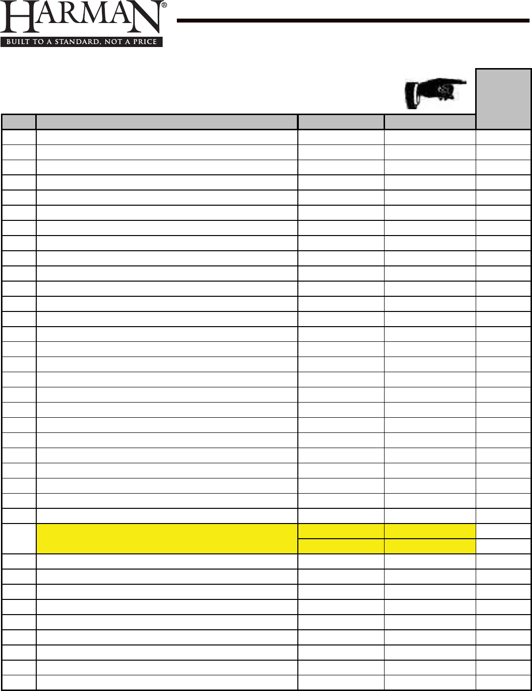
Service Parts TL2.0
Beginning Manufacturing Date: Sept 2011
Ending Manufacturing Date: Active
IMPORTANT: THIS IS DATED INFORMATION. Parts must be ordered from a dealer or
distributor. Hearth and Home Technologies does not sell directly to consumers. Provide
model number and serial number when requesting service parts from your dealer or distributor.
Stocked
at Depot
ITEM DESCRIPTION COMMENTS PART NUMBER
18 Ash door asy, painted with handle 1-10-856005A
Ash door latch only 3-00-249149
Ash door gasket 5 ft 1-00-10000 Y
Ash door hinge with hardware 1-00-856020
Ash door roller with hardware 1-00-06902
Ash Door Wood Handle Pkg of 3 3-40-08746-3
19 Air slide rod bracket with hardware 1-00-856008 Y
20 Air control weldment 1-10-856004W Y
21 Air slide 1-10-856003W Y
22 Ash pan 1-10-856006A Y
23 Combustion shoe brick 3-40-00100 Y
Shoe brick gasket 3-44-06951 Y
24 Side brick insulation Qty 2 req 3-40-856086 Y
25 Right side panel, painted 2-00-856024B Y
26 Heat shield mounting plate, painted 2-00-856026B
27 Rear heat shield, painted with hardware 1-00-856025 Y
Blower Blockoff 1-00-856019
Brick Retainers, Side Set of 2 1-00-06945 Y
Cast Weld on Door Hinge Qty 2 req 3-00-773813
Combustion Package Cap 2-00-358150B Y
Distribution Blower 7000-537
Power Cord 3-20-06652 Y
Snap Disc Control 3-20-408412 Y
Touch up Paint Pre 008840396 3-42-1990
Post 008840396 3-42-19905
Ashlip Trim Brushed Stainless 3-43-4722386-7
Door Trim Brushed Stainless 3-43-856015-7
Tile Trim Brushed Stainless 3-43-06729-7
Spring Clips (Required for installation of Tile Frame) Pkg of 20 3-31-232547-20
Additonal service parts on following page
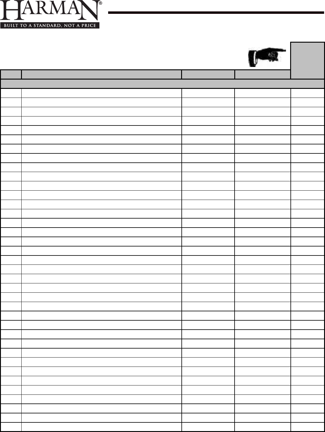
Service Parts TL2.0
Beginning Manufacturing Date: Sept 2011
Ending Manufacturing Date: Active
IMPORTANT: THIS IS DATED INFORMATION. Parts must be ordered from a dealer or
distributor. Hearth and Home Technologies does not sell directly to consumers. Provide
model number and serial number when requesting service parts from your dealer or distributor.
Stocked
at Depot
ITEM DESCRIPTION COMMENTS PART NUMBER
Hardware Packages
#10-24 x 1/4" Alloy Steel Black Oxide Cup Point SSS Pkg of 100 3-30-2006-100 Y
Acorn Nut, 10-24 Nickel Plated Pkg of 50 3-30-8014-50 Y
Ball Plunger, 5/16 x 1/2 Pkg of 3 3-31-5500-3 Y
Bolt, Case Hardened Zinc Flange, 1/4-20 x 3/8 Pkg of 50 3-30-2000-50 Y
Bolt, HCS 3/8-16 x1 1/4 Pkg of 25 3-30-1135-25 Y
Bolt,1/4-20 x 1/2" Grade 8.2 Zinc SAE Flange Pkg of 50 3-30-2001-50 Y
Cap Screw, 1/4-20 x 1 1/2 Grade 8 Yellow Zinc Hex Head Pkg of 25 3-30-1119-25 Y
Cap Screw, 1/4-20 x 1/2 Grade 8 Yellow Zinc Hex Head Pkg of 50 3-30-1109-50 Y
Cap Screw, 1/4-20 x 3/4 Grade 8 Yellow Zinc Hex Head Pkg of 50 3-30-1113-50 Y
Cap Screw, 1/4-20 x 5/8 Grade 5 Zinc Hex Pkg of 100 3-30-1110-100 Y
Cap Screw, 5/16-18 x 1/2" Grade 5 Zinc Plated Hex Pkg of 50 3-30-1122-50 Y
Cap Screw,1/4-20 x 3/8" Grade 5 Zinc Hex Pkg of 25 3-30-1106-25 Y
Cap Screw,5/16"-18 x 3/4" Grade 8 Plain Finish Hex Pkg of 50 3-30-1126-50 Y
Dowel Pin, 3/16 x 2" Bright Finish Steel Pkg of 15 3-30-2005-15 Y
Lock Nut, 10-32 Grade A Zinc Plated Top Pkg of 100 3-30-8019-100 Y
Machine Screw, 1/4"-20 x 2 1/2" Phillips Round Head Zinc Pltd Pkg of 25 3-30-6007-25 Y
Machine Screw, 10-32 x 3/8" Phillips Round Head Zinc Plated Pkg of 100 3-30-6005-100 Y
Nut , Centerlock,1/4-20 Pkg of 50 3-30-8020-100 Y
Nut, Grade 5 Zinc Plated Finished Hex, 5/16"-18 Pkg of 100 3-30-8005-100 Y
Nut,1/4"-20 Zinc Plated Finished Hex Pkg of 100 3-30-8004-100 Y
Nut,1/4-20 Grade C Zinc Plated Top Lock Pkg of 50 3-30-8021-50 Y
Rivet, 1/8" Dia .032-.062" Grip Range AB4-1CLD Alum Pkg of 100 3-30-7900-100 Y
Screw, #10-24 x 3/8" Alloy Steel Black Oxide Button Head Cap Pkg of 100 3-30-3011-100 Y
Screw, 5/16"-18 x 3/8" Alloy Steel Black Oxide Knurled Point SSS Pkg of 25 3-30-2004-25 Y
Screw, BLK OX, HWH TCS 10-24X1/2 Pkg of 100 3-30-1101-100 Y
Screw, Hex Washer Slot T23 Zinc Thread Cutting ,1/4-20x5/8" Pkg of 50 3-30-1111-50 Y
Screw,1/4"-20 x 3/8" Alloy Steel Black Oxide Button Head Cap Pkg of 100 3-30-3014-100 Y
Washer, 5/16" Zinc Plated SAE Flat Pkg of 50 3-30-0205-50 Y
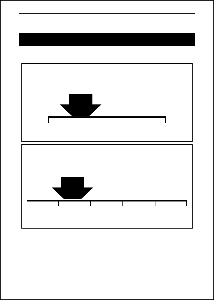
Meets EPA particulate matter (smoke) control requirements for
noncatalytic wood heaters built on or after July 1, 1990.
Wood heaters with higher efciencies cost less to operate.
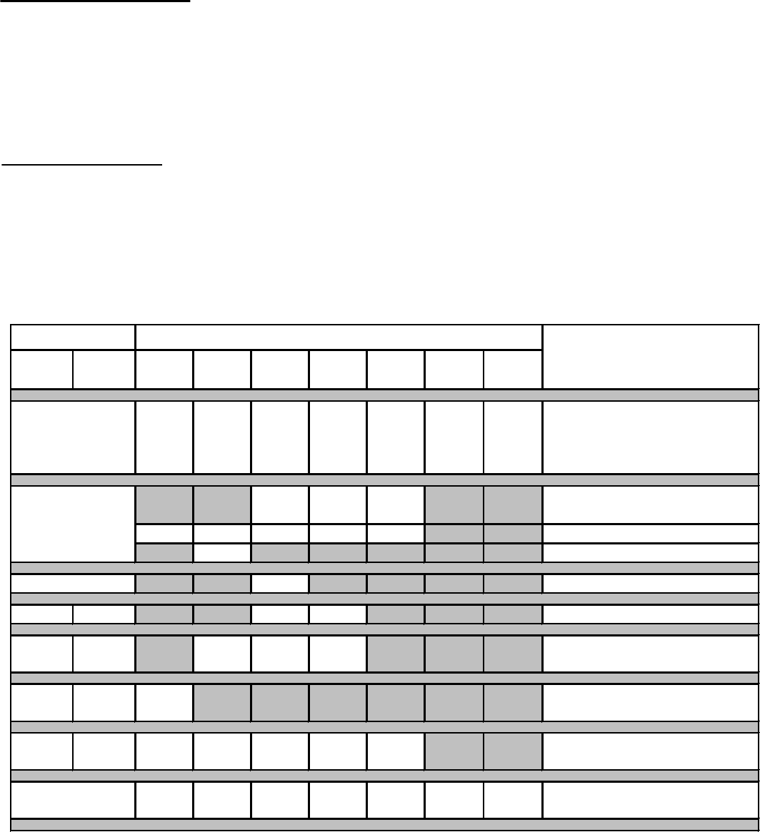
4021-645F 02-18-13 Page 1 of 2
Hearth & Home Technologies
LIMITED LIFETIME WARRANTY
Hearth & Home Technologies, on behalf of its hearth brands (”HHT”), extends the following warranty for HHT
gas, wood, pellet, coal and electric hearth appliances that are purchased from an HHT authorized dealer.
WARRANTY COVERAGE:
HHT warrants to the original owner of the HHT appliance at the site of installation, and to any transferee taking ownership
of the appliance at the site of installation within two years following the date of original purchase, that the HHT appliance
will be free from defects in materials and workmanship at the time of manufacture. After installation, if covered compo-
nents manufactured by HHT are found to be defective in materials or workmanship during the applicable warranty period,
HHT will, at its option, repair or replace the covered components. HHT, at its own discretion, may fully discharge all of its
obligations under such warranties by replacing the product itself or refunding the verified purchase price of the product
itself. The maximum amount recoverable under this warranty is limited to the purchase price of the product. This warranty
is subject to conditions, exclusions and limitations as described below.
WARRANTY PERIOD:
Warranty coverage begins on the date of original purchase. In the case of new home construction, warranty coverage
begins on the date of first occupancy of the dwelling or six months after the sale of the product by an independent,
authorized HHT dealer/ distributor, whichever occurs earlier. The warranty shall commence no later than 24 months
following the date of product shipment from HHT, regardless of the installation or occupancy date. The warranty period for
parts and labor for covered components is produced in the following table.
The term “Limited Lifetime” in the table below is defined as: 20 years from the beginning date of warranty coverage for
gas appliances, and 10 years from the beginning date of warranty coverage for wood, pellet, and coal appliances. These
time periods reflect the minimum expected useful lives of the designated components under normal operating conditions.
See conditions, exclusions, and limitations on next page.
Parts Labor Gas Wood Pellet EPA
Wood
Coal Electric Venting
XXXXXXX
All parts and material except as
covered by Conditions,
Exclusions, and Limitations
listed
XXX
Igniters, electronic components,
and glass
X X X X X Factory-installed blowers
X Molded refractory panels
X Firepots and burnpots
5 years 1 year X X Castings and baffles
7 years 3 years X X X Manifold tubes,
HHT chimney and termination
10
years
1 year X Burners, logs and refractory
Limited
Lifetime
3 years X X X X X Firebox and heat exchanger
XXXXXXX All replacement parts
beyond warranty period
Warranty Period HHT Manufactured Appliances and Venting
1 Year
Components Covered
3 years
2 years
90 Days

4021-645F 02-18-13 Page 2 of 2
WARRANTY CONDITIONS:
• This warranty only covers HHT appliances that are purchased through an HHT authorized dealer or distributor. A list of
HHT authorized dealers is available on the HHT branded websites.
• This warranty is only valid while the HHT appliance remains at the site of original installation.
• This warranty is only valid in the country in which the HHT authorized dealer or distributor that sold the appliance
resides.
• Contact your installing dealer for warranty service. If the installing dealer is unable to provide necessary parts, contact
the nearest HHT authorized dealer or supplier. Additional service fees may apply if you are seeking warranty service
from a dealer other than the dealer from whom you originally purchased the product.
• Check with your dealer in advance for any costs to you when arranging a warranty call. Travel and shipping charges
for parts are not covered by this warranty.
This warranty is void if:
• The appliance has been over-fired or operated in atmospheres contaminated by chlorine, fluorine, or other damaging
chemicals. Over-firing can be identified by, but not limited to, warped plates or tubes, rust colored cast iron, bubbling,
cracking and discoloration of steel or enamel finishes.
• The appliance is subjected to prolonged periods of dampness or condensation.
• There is any damage to the appliance or other components due to water or weather damage which is the result of, but
not limited to, improper chimney or venting installation.
LIMITATIONS OF LIABILITY:
• The owner’s exclusive remedy and HHT’s sole obligation under this warranty, under any other warranty, express or
implied, or in contract, tort or otherwise, shall be limited to replacement, repair, or refund, as specified above. In no
event will HHT be liable for any incidental or consequential damages caused by defects in the appliance. Some states
do not allow exclusions or limitation of incidental or consequential damages, so these limitations may not apply to you.
This warranty gives you specific rights; you may also have other rights, which vary from state to state. EXCEPT TO
THE EXTENT PROVIDED BY LAW, HHT MAKES NO EXPRESS WARRANTIES OTHER THAN THE WARRANTY
SPECIFIED HEREIN. THE DURATION OF ANY IMPLIED WARRANTY IS LIMITED TO DURATION OF THE
EXPRESSED WARRANTY SPECIFIED ABOVE.
This warranty does not cover the following:
• Changes in surface finishes as a result of normal use. As a heating appliance, some changes in color of interior and
exterior surface finishes may occur. This is not a flaw and is not covered under warranty.
• Damage to printed, plated, or enameled surfaces caused by fingerprints, accidents, misuse, scratches, melted items,
or other external sources and residues left on the plated surfaces from the use of abrasive cleaners or polishes.
• Repair or replacement of parts that are subject to normal wear and tear during the warranty period. These parts
include: paint, wood, pellet and coal gaskets, firebricks, grates, flame guides, batteries and the discoloration of glass.
• Minor expansion, contraction, or movement of certain parts causing noise. These conditions are normal and com-
plaints related to this noise are not covered by this warranty.
• Damages resulting from: (1) failure to install, operate, or maintain the appliance in accordance with the installation
instructions, operating instructions, and listing agent identification label furnished with the appliance; (2) failure to
install the appliance in accordance with local building codes; (3) shipping or improper handling; (4) improper opera-
tion, abuse, misuse, continued operation with damaged, corroded or failed components, accident, or improperly/
incorrectly performed repairs; (5) environmental conditions, inadequate ventilation, negative pressure, or drafting
caused by tightly sealed constructions, insufficient make-up air supply, or handling devices such as exhaust fans or
forced air furnaces or other such causes; (6) use of fuels other than those specified in the operating instructions; (7)
installation or use of components not supplied with the appliance or any other components not expressly authorized
and approved by HHT; (8) modification of the appliance not expressly authorized and approved by HHT in writing;
and/or (9) interruptions or fluctuations of electrical power supply to the appliance.
• Non-HHT venting components, hearth components or other accessories used in conjunction with the appliance.
• Any part of a pre-existing fireplace system in which an insert or a decorative gas appliance is installed.
• HHT’s obligation under this warranty does not extend to the appliance’s capability to heat the desired space. Informa-
tion is provided to assist the consumer and the dealer in selecting the proper appliance for the application. Consider-
ation must be given to appliance location and configuration, environmental conditions, insulation and air tightness of
the structure.
38
Dry Seasoned Wood Only!
TL2.0 Woodburning Stove
Save These Instructions 3-90-08560
Service & Maintenance Log
Date Of Service Performed By Description Of Service
Proudly Printed On 100% Recycled Paper
At Harman, we build each product to a standard, not a price.
This powerful heating appliance boasts uncompromising
attention to detail and helps preserve our planet by using
environmentally responsible fuels.
(Signature of Boxer)
Your premium quality hearth product designed and assembled
by the experienced and skilled members at Harman in Halifax,
PA, USA.
