Harman MICROCORE Mixing Console User Manual onair
Harman International Industries, Inc Mixing Console onair
UserManual.wiki
>
Harman
>
MICROCORE User Manual
User Manual
Navigation menu
Upload a User Manual
Namespaces
Wiki Guide
HTML
PDF
Info
Views
User Manual
Discussion / Help
Navigation
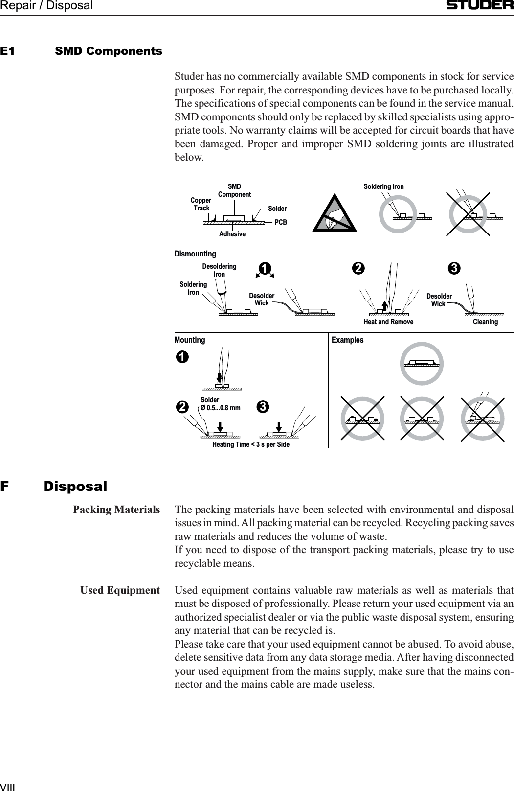
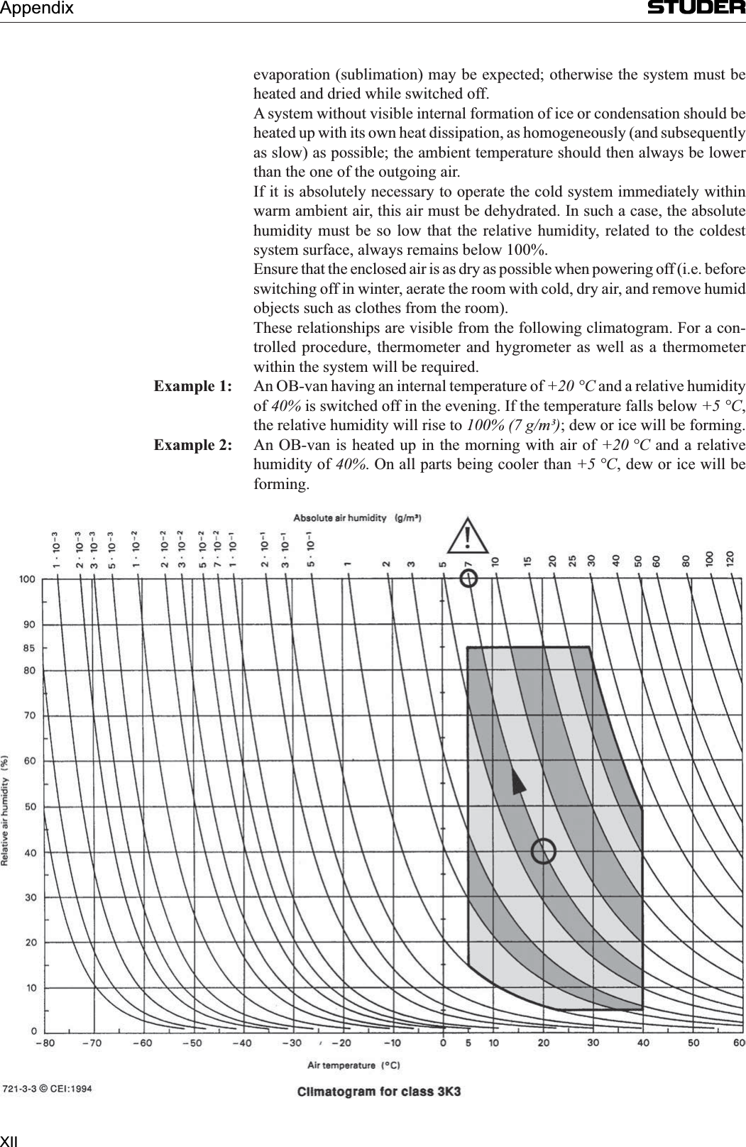
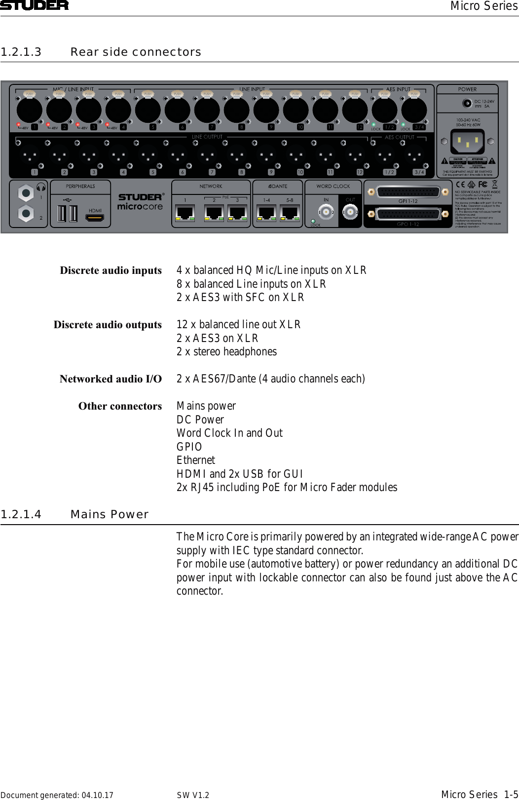
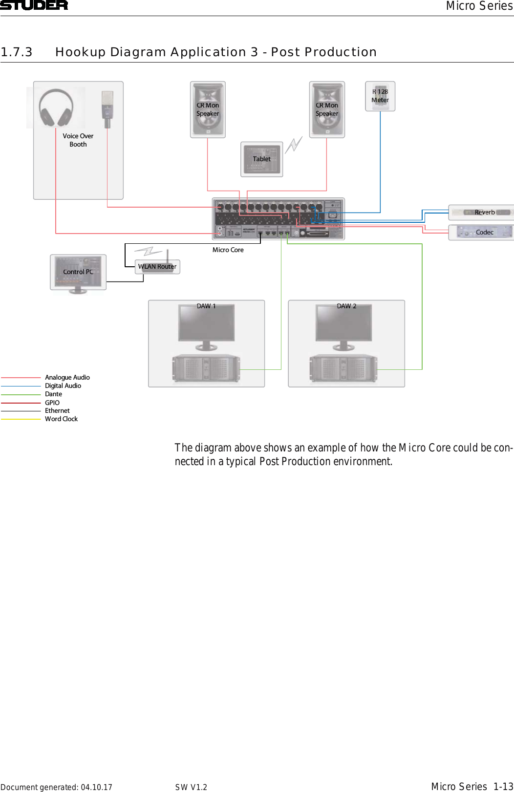
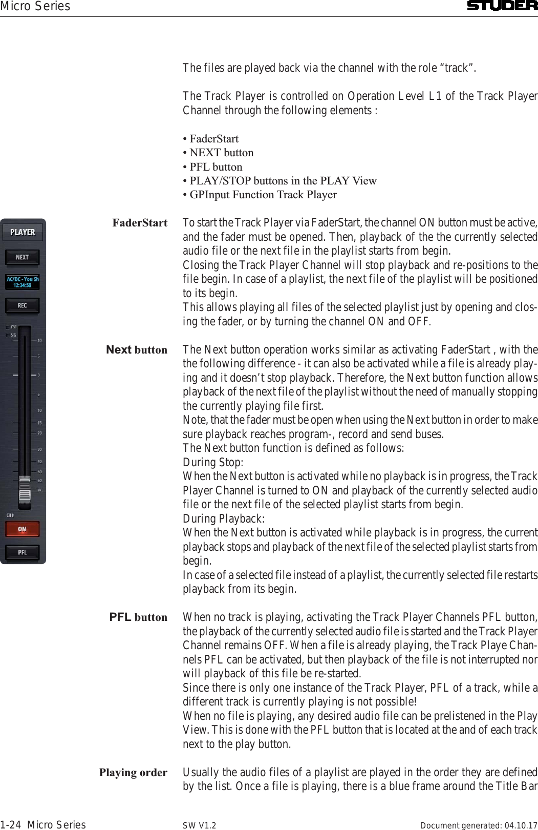
![II ! ! Although your new console will not make any noise until you feed it signals, it has the capability to produce sounds that, when monitored through a moni-tor system or headphones, can damage hearing over time.The table below is taken from the Occupational Safety & Health Administration directive on occupational noise exposure (1926.52): Duration per day [h] Sound level [dBA, slow response] 8906924953972 1001.5 1021 1050.5 110<0.25 115Conforming to this directive will minimise the risk of hearing damage caused by long listening periods. A simple rule to follow is: The longer you listen, the lower the average volume should be. Please take care when working with your audio system – if you are manipulating controls which you don’t understand (which we all do when we are learning), make sure your monitoring level is turned down. Remember that your ears are the most important tool of your trade. Look after them, and they will look after you. Most importantly: Don’t be afraid to experiment to find out how each parameter affects the sound; this will extend your creativity and help you to get the best results.!Safety Information](https://usermanual.wiki/Harman/MICROCORE/User-Guide-3749418-Page-4.png)
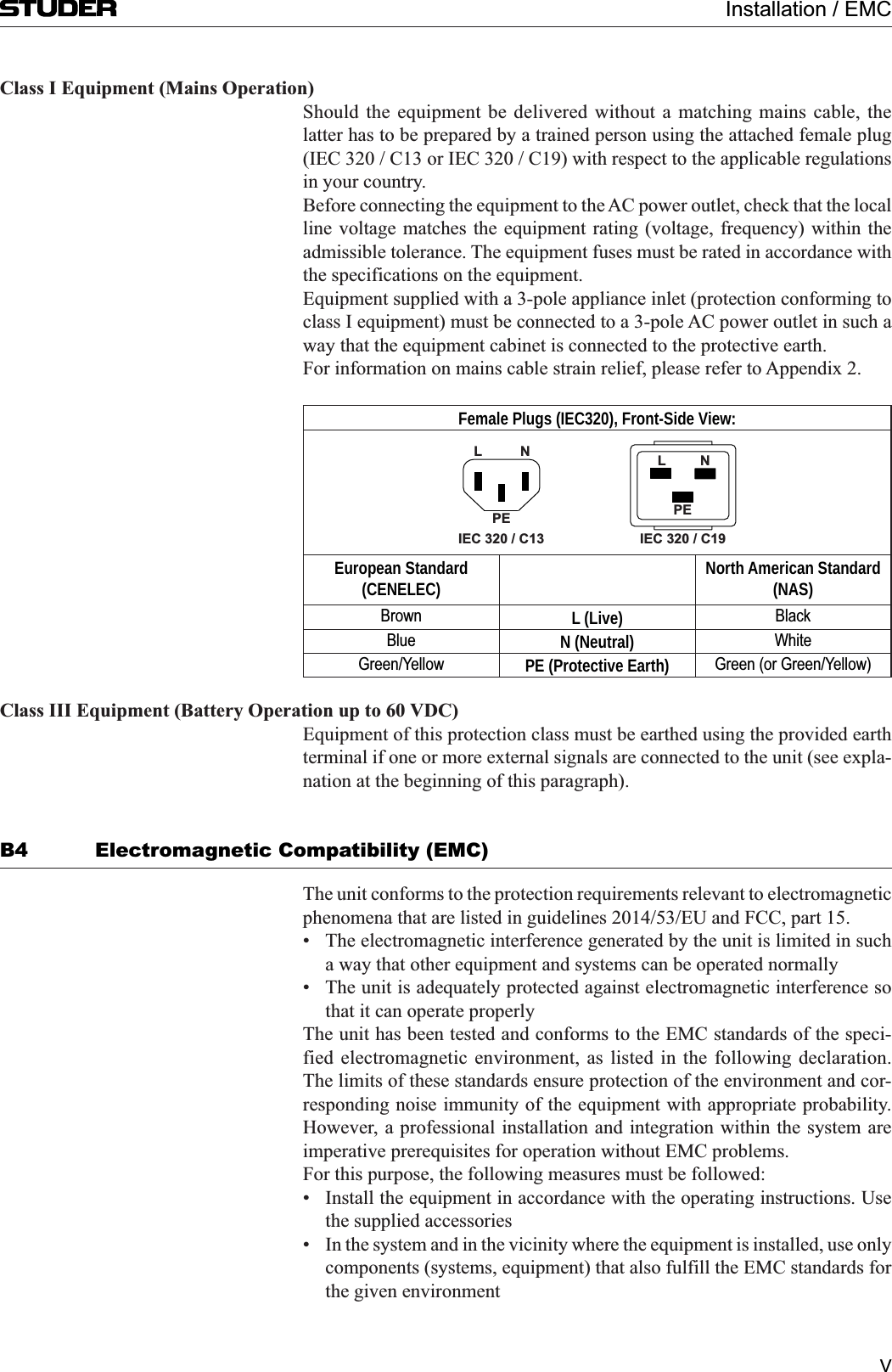
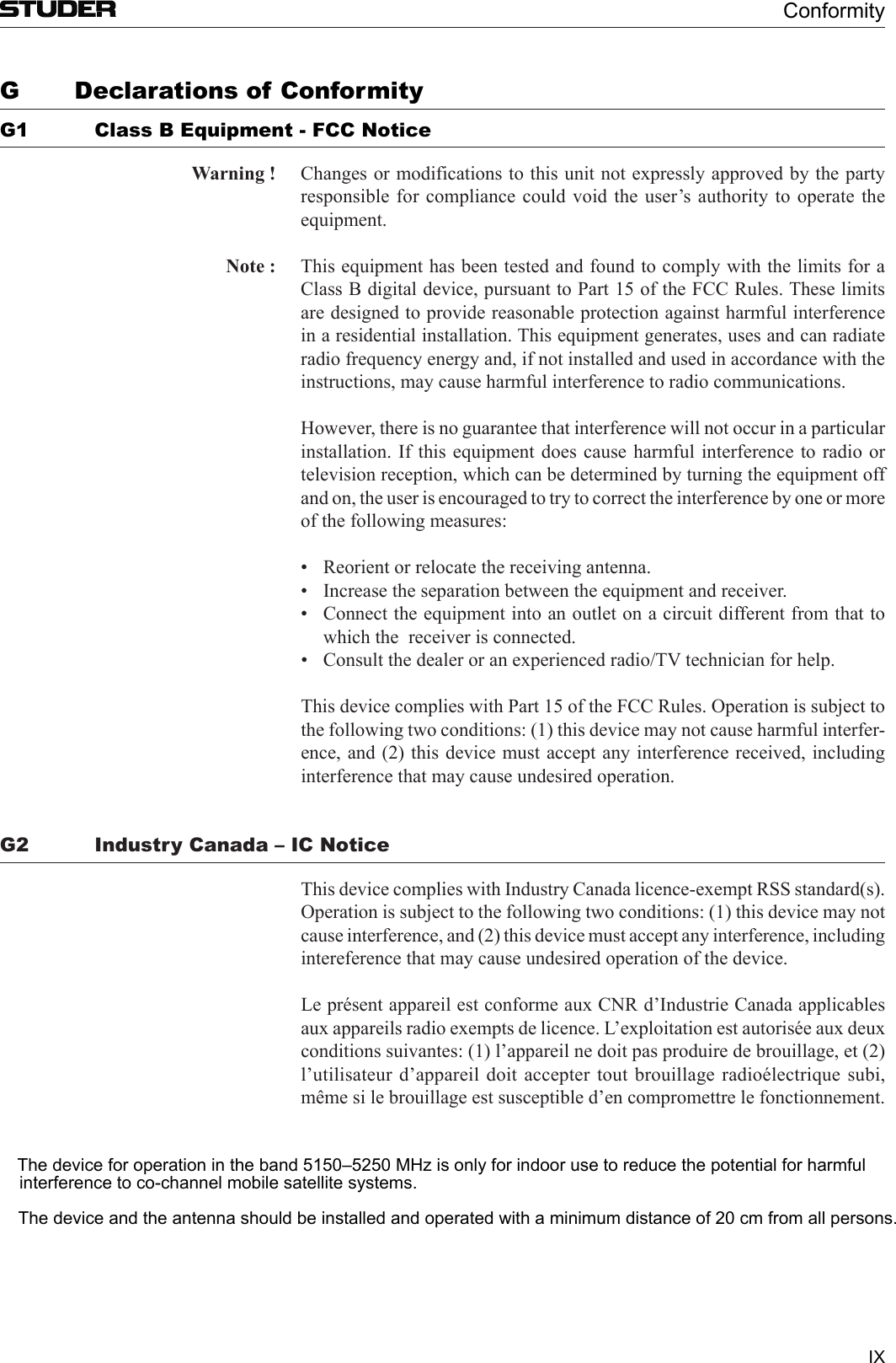
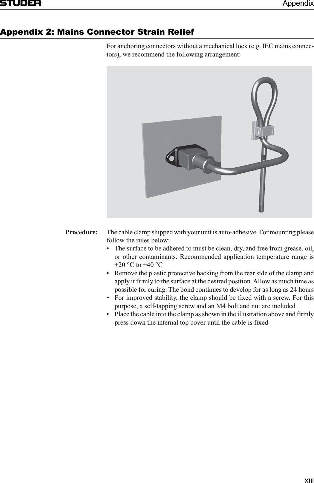
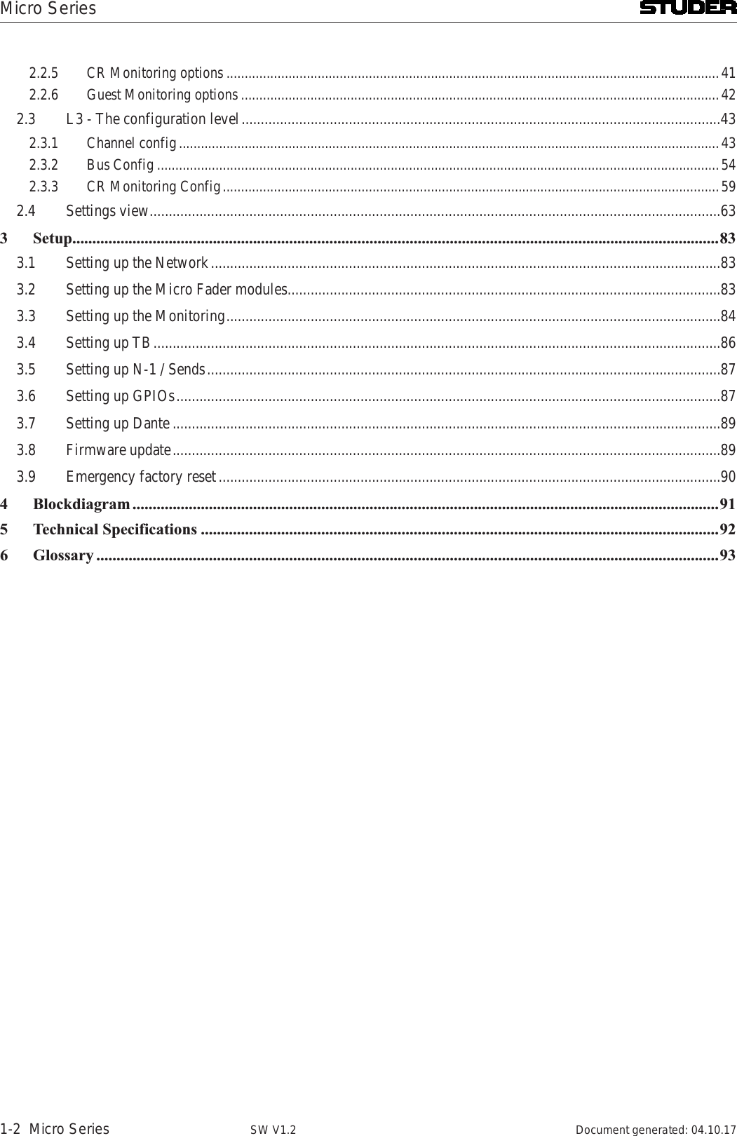
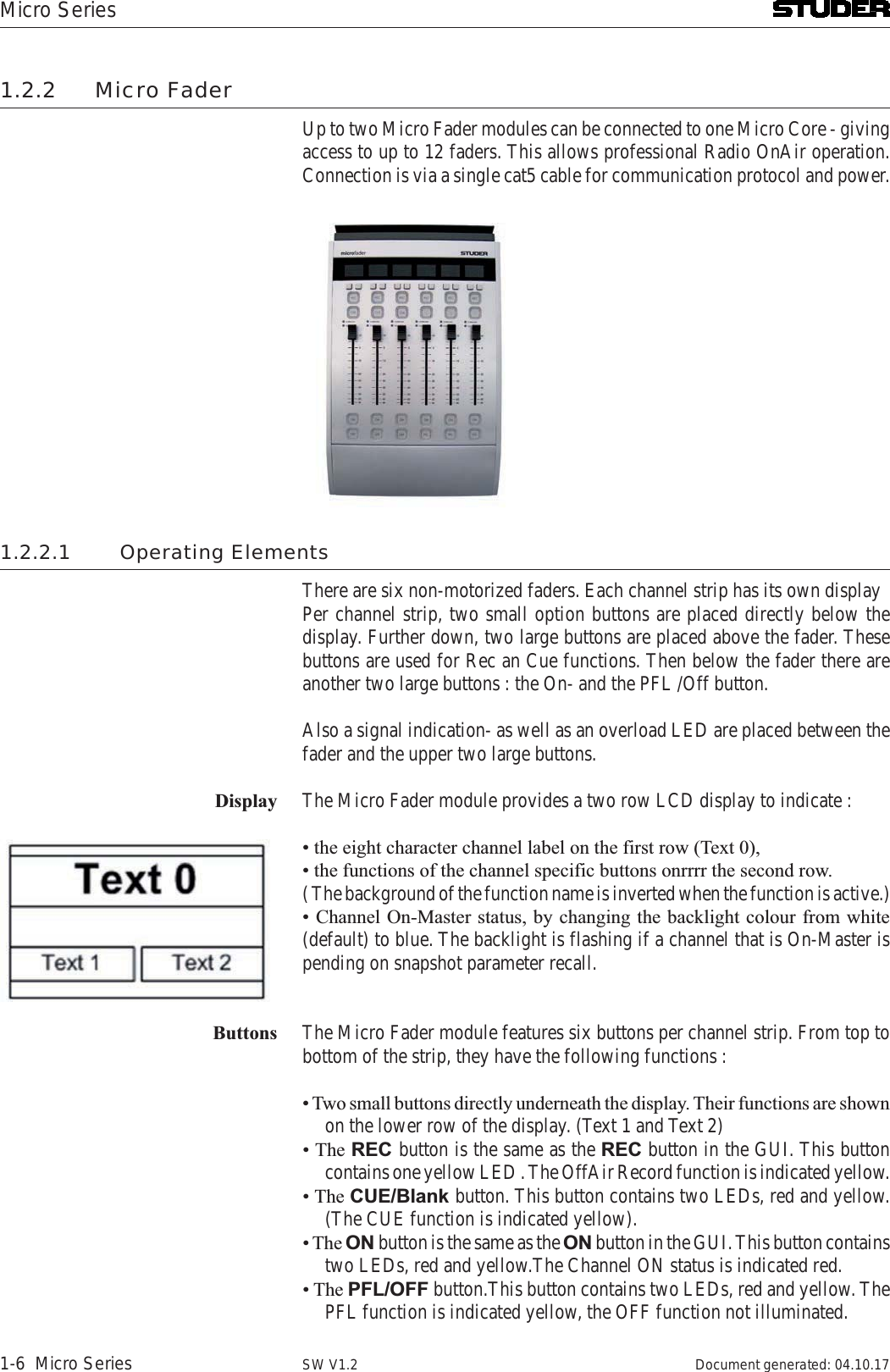
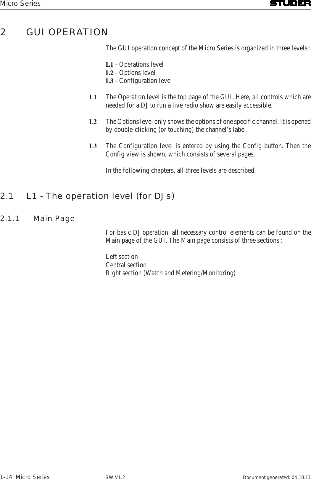
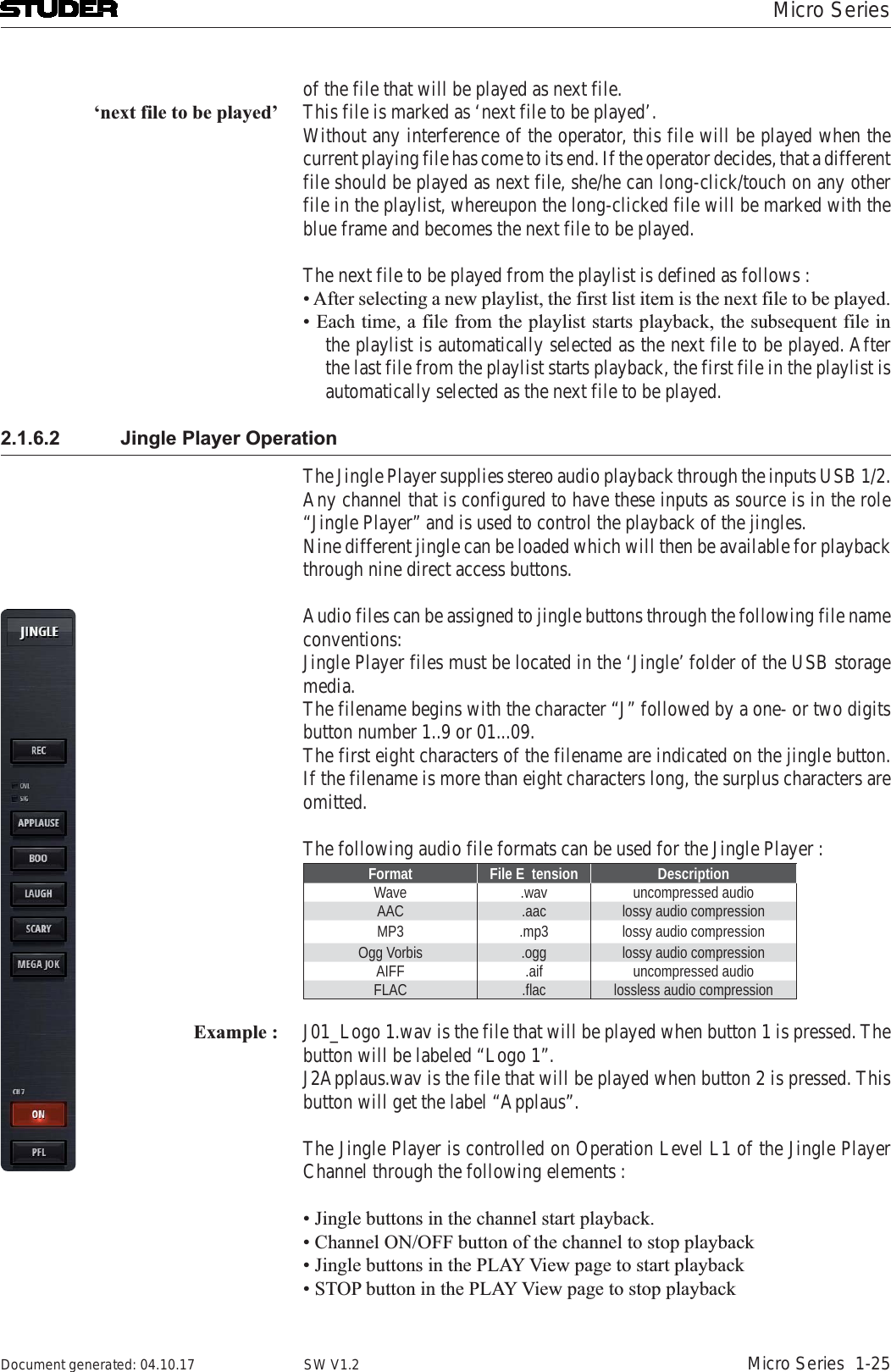
![Micro SeriesMicro Series 1-17Document generated: 04.10.17 SW V1.22.1.3 Chan ViewThe channel view shows the faderstrips of the mixers input channels. All twelve input channels are shown - by using the scroll buttons in the central section the operator can navigate to the desired faderstrips. Also swiping can be used on a touchscreen to navigate between the faderstrips.The operating elements that are common to all channels are these (channel role “Default”) :12[1] Label The channel label display shows the channels name. This name can be entered in the Options page of the channel. The labels background changes from grey to blue, when the channel is ‚On-Master‘.[2] Rec button The Rec button assigns a channel to the record bus.[3] OVL Indicator The overload indicator is used to indicate analogue input clipping (A/D con-verter), which means overload is never illuminated for digital sources. For](https://usermanual.wiki/Harman/MICROCORE/User-Guide-3749418-Page-34.png)
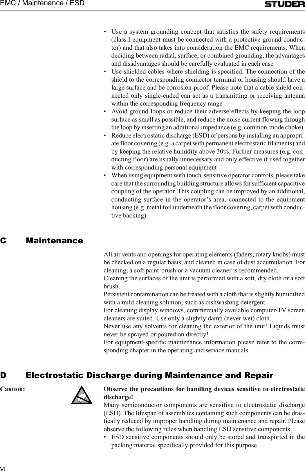
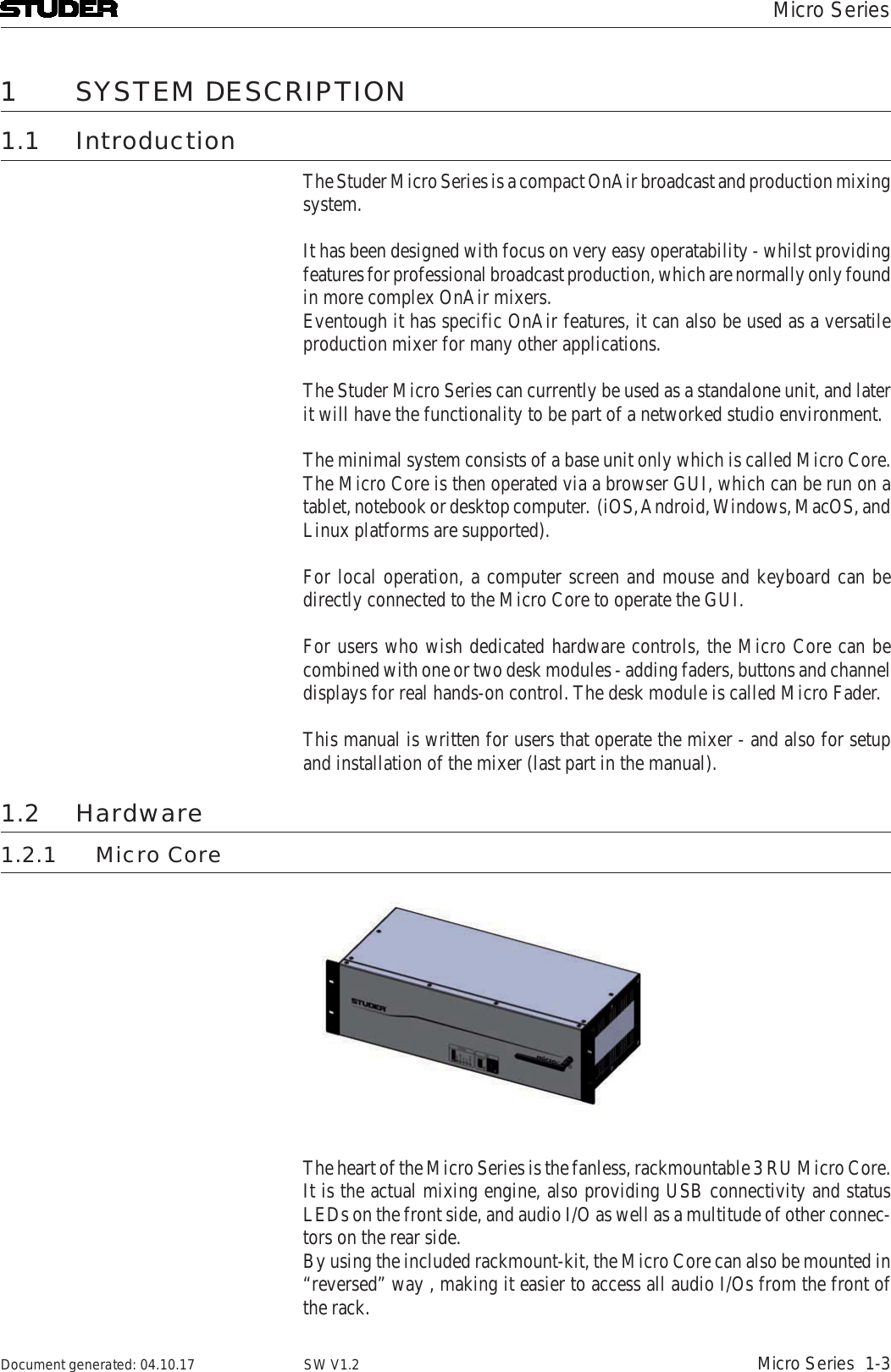
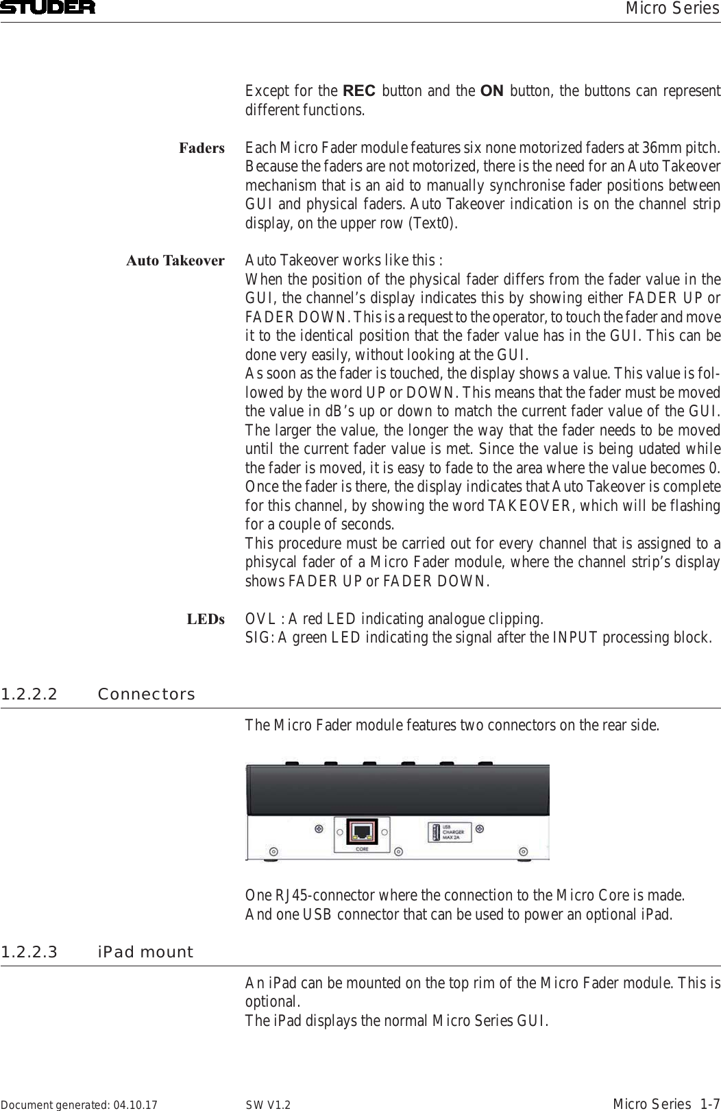
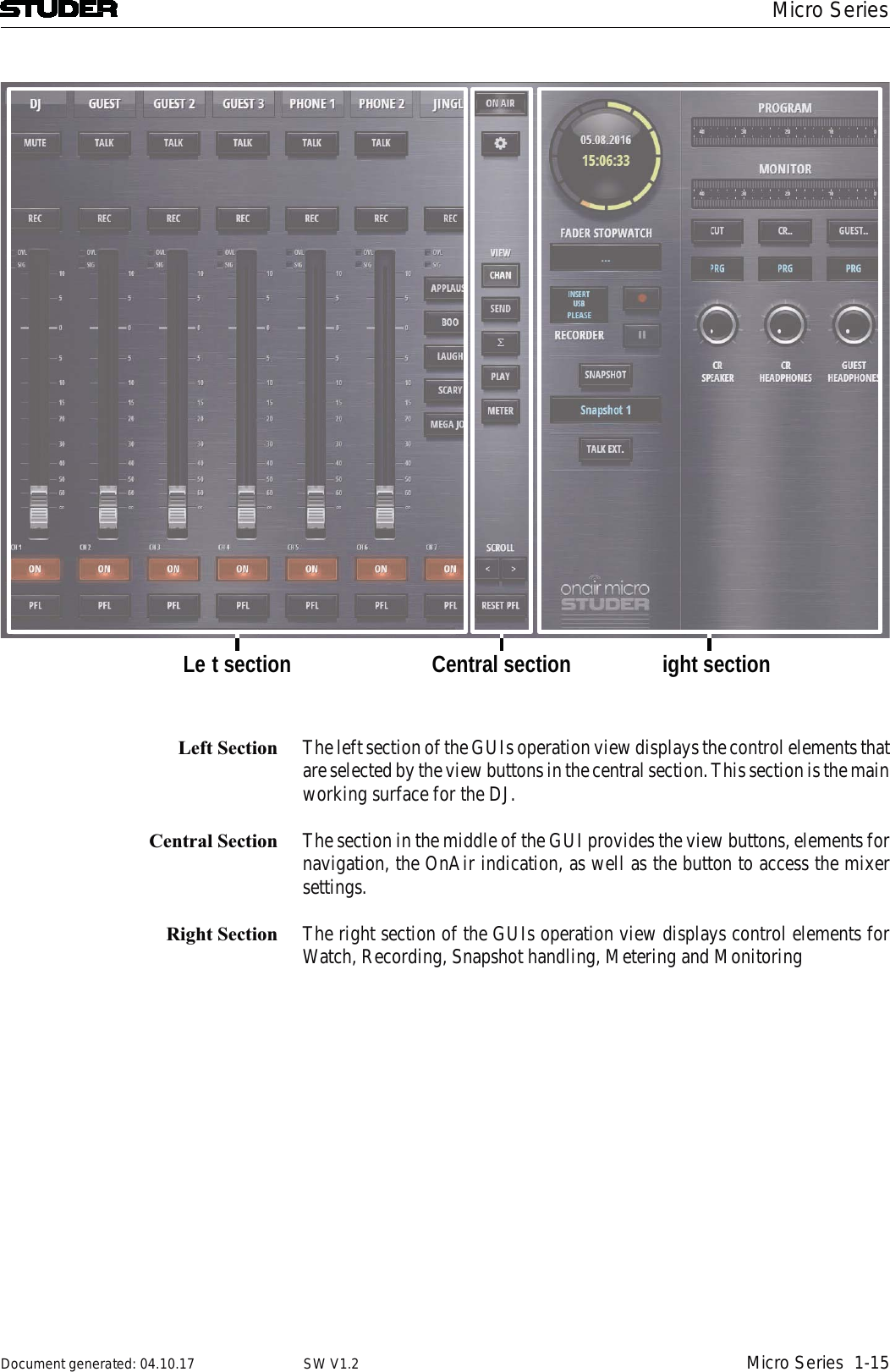
![Micro Series1-18 Micro Series Document generated: 04.10.17SW V1.2channels with analogue inputs, OVL is illuminated as soon as the input level, before input calibration, reaches 0dBFS.[3] SIG Indicator The green signal indicator is illuminated as soon as the signal is > -40dB. The signal is captured after the INPUT processing block and therefore it is also influenced by the analogue gain as well as the digital input calibration of the channel.[4] Fader The channel fader. It can be operated by mouse or touch. The mousewheel can also be used to operate the fader when hovering the mousepointer anywhere over the fader area.[5] On button The On button activates the channel. When the fader is open, the On button toggles the channel ‚on-air‘ and ‚off-air‘.[6] PFL button The PFL button allows the operator to pre- listen to this channel even if the fader is closed or the channel is not switched to ‚On‘. PFL stands for PreF-adeListening. The Reset PFL button in the central section releases all channels from PFL.The channel of other roles than “Default” have additional buttons :Role : DJ Guest Input for sends Track Jingle1 2 2](https://usermanual.wiki/Harman/MICROCORE/User-Guide-3749418-Page-35.png)
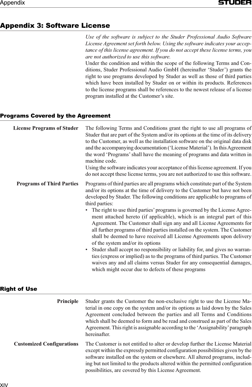
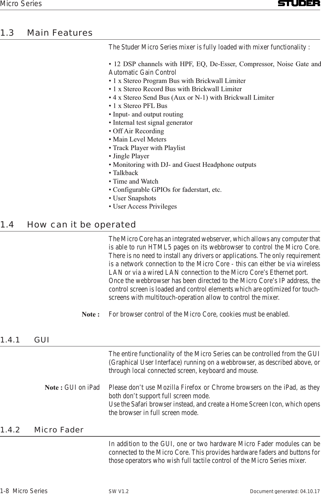
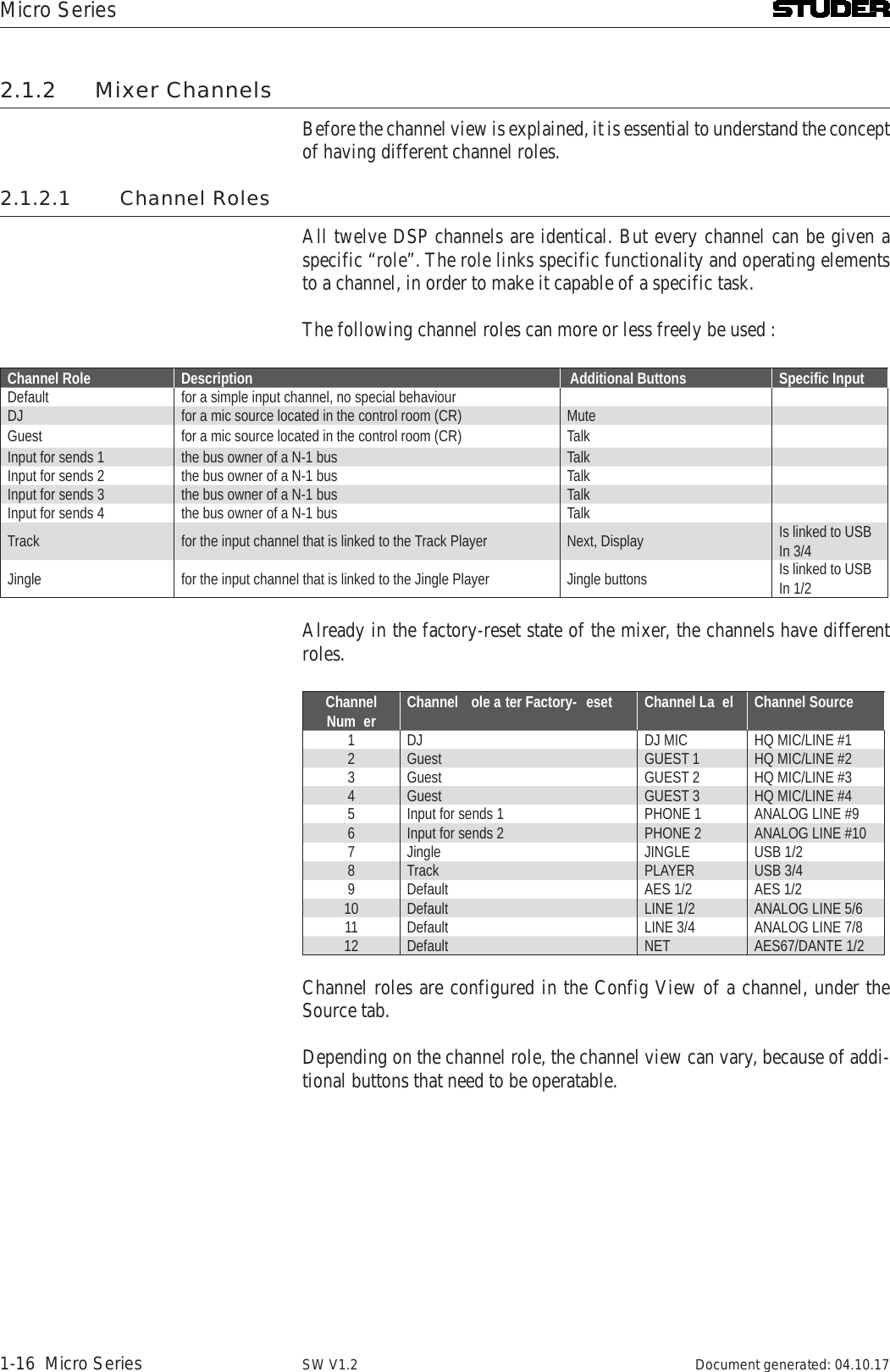
![Micro SeriesMicro Series 1-19Document generated: 04.10.17 SW V1.2[1] Mute button The Mute button is intended for the use as a cough-button. It is only available for channels of the role DJ.[2] Talk button The Talk button allows the DJ to talk either to a Guest via the Guest’s head-phone monitor - or to a N-1 output of a channel of the role “Input for sends”.[3] Next button The Next button allows to change to the next audio file of the current playing playlist. For details please see chapter 2.1.6.1 Track Player Operation.[4] Status Display The Status Display of the Track Player Channel shows the name of the current title, as well as a progress bar and the current playing time.[5] Jingle buttons The Jingle buttons are used to play specific Jingles from the Jingle channel. More Jingle buttons can be found in the Play view.](https://usermanual.wiki/Harman/MICROCORE/User-Guide-3749418-Page-36.png)
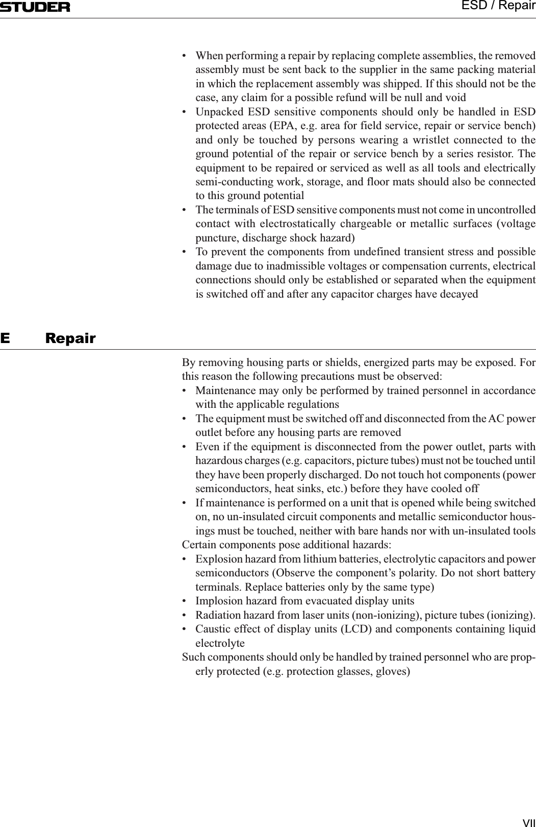
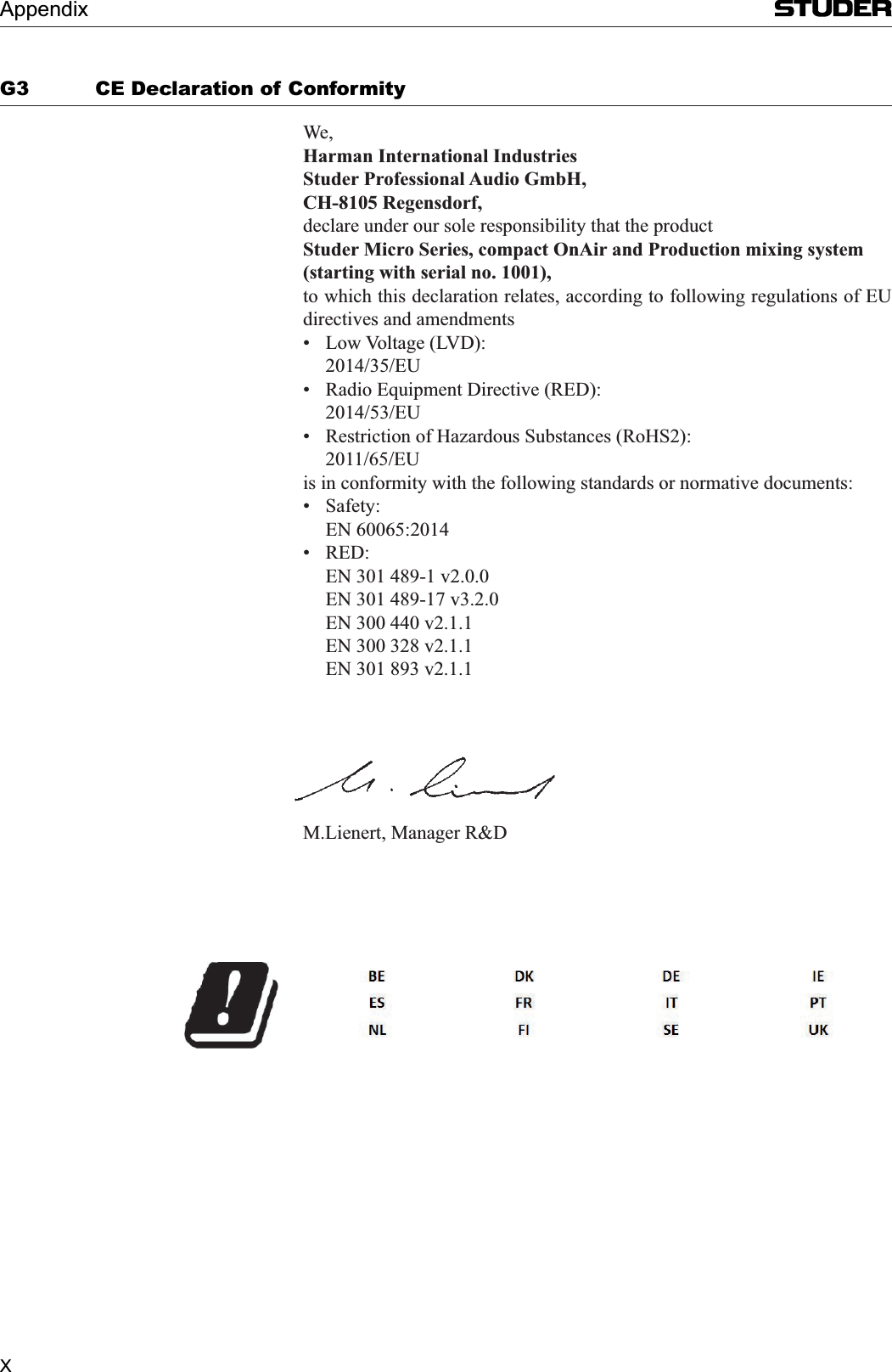
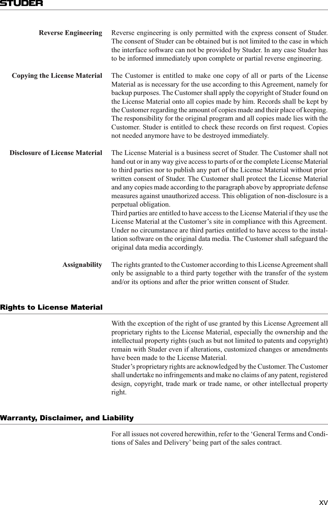
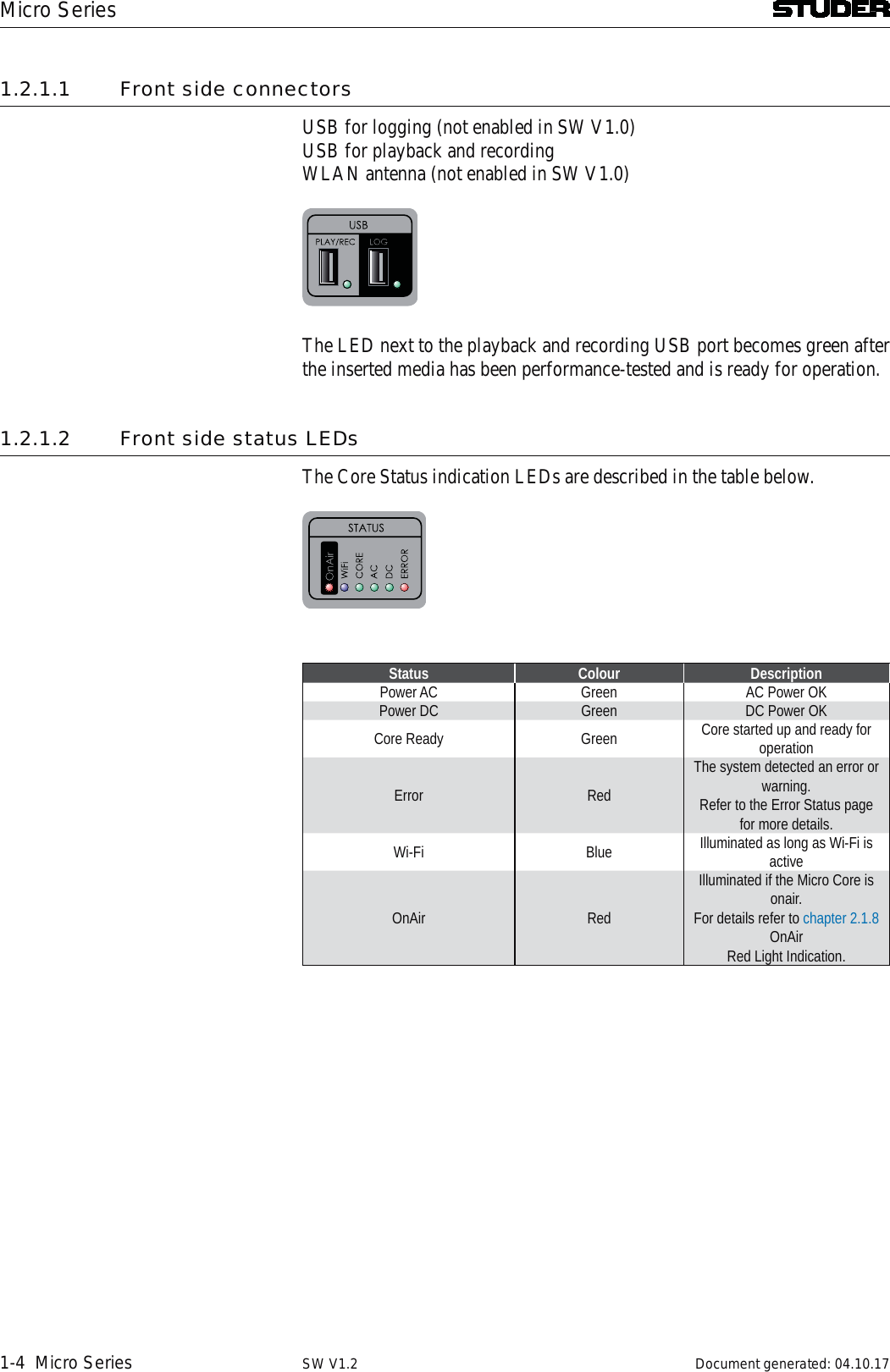
![Micro Series1-20 Micro Series Document generated: 04.10.17SW V1.22.1.4 Send ViewThe send view shows the mixers four send channels. Each of these four chan-nels can either be an Aux or N-1 send. Here, the send master faders can be operated.[][2][][][][][1] Label The label display shows the send channels name. This name can be entered in the Options page of the send channel. [2] Talk button This button can be used to talk to the output of this send channel. [5] SIG Indicator The green signal indicator is illuminated as soon as the signal on the send bus is > -40dB. The signal is captured before the send fader.[6] Fader The send fader. It can be operated by mouse or touch. The mousewheel can also be used to operate the fader when hovering the mousepointer anywhere over the fader area.[7] On button The On button activates the send channel. [8] PFL button The PFL button allows the operator to pre- listen to this channel even if the fader is closed or the channel is not switched to ‚On‘. PFL stands for PreF-adeListening. The Reset PFL button in the central section releases all channels from PFL.](https://usermanual.wiki/Harman/MICROCORE/User-Guide-3749418-Page-37.png)
![Micro SeriesMicro Series 1-21Document generated: 04.10.17 SW V1.22.1.5 Sum ViewThe sum view shows the master faders of the program (PRG) - as well as the recording (REC) bus .1[1] Label The label display shows the bus name. This name can be entered in the Options page of the bus. [5] SIG Indicator The green signal indicator is illuminated as soon as the signal is on the send bus is > -40dB. The signal is captured before the bus fader.[6] Fader The bus fader. It can be operated by mouse or touch. The mousewheel can also be used to operate the fader when hovering the mousepointer anywhere over the fader area.[8] PFL button The PFL button allows the operator to pre- listen to this bus even if the fader is closed. PFL stands for PreFadeListening. The Reset PFL button in the central section releases all channels from PFL.](https://usermanual.wiki/Harman/MICROCORE/User-Guide-3749418-Page-38.png)
![Micro Series1-22 Micro Series Document generated: 04.10.17SW V1.22.1.6 Play(er) ViewThe play(er) view changes the left section to show the player window.211[1] Media Media and playlist selection.[2] Title bars The title as well as the name of the artist is listed here. The blue progress bar shows the current position in the title. Also the total playing time is displayed at the end of the bar.[3] Play mode Automatic or Manual player mode. The Play Mode defines the behaviour when on-air playback of a file reaches its end.Manual If the file is played to its end before the Track Player Channel is closed or playback is stopped by the user, the Track Player Channel is turned to off.Auto If a file is played to its end before the Track Player Channel is closed or play-back is stopped by the user, playback of the currently selected audio file starts automatically from begin. In case of a playlist, the next file of the playlist starts automatically from begin. This allows playing all files of the selected playlist without further user action.[4] Currently playing title display Displays the currently playing title as well as the current playing time. The blue progress bar shows the current position in the title.[5] Play/Stop buttons Titles can be played and stopped directly with these dedicated play/stop but-tons in the Player View.Clicking or touching the Play button turns the Track Player Channel to On](https://usermanual.wiki/Harman/MICROCORE/User-Guide-3749418-Page-39.png)
![Micro SeriesMicro Series 1-23Document generated: 04.10.17 SW V1.2and starts playback of a dedicated file from begin, regardless if any file is already playing or not. Note, that the fader must be open when using Play in order to make sure playback reaches program-, record and send buses. If the Stop button of a currently playing file is pressed, playback stops, the Track Player Channel is turned to Off.[6] PFL buttons The PFL button is used to pre-listen the current selected audio file.As long as the Track Player Channel is not open : Note, that PFL is automatically deactivated, when the Track Player Channel reaches On-Master status.If the file is played to its end before PFL is deactivated by the user, playback stops and PFL is turned off.[7] Remaining time display Here, the remaining time of the playlist is displayed.[8] Stop button Titles can be stopped directly with this global stop button.[9] Jingle buttons The Jingle buttons are used to play specific Jingles from the Jingle channel. Here in the Player view, nine buttons are shown, where in the channel view depending on the size of the GUI, sometimes not all nine buttons can be shown.[10] Stop button Jingles can be stopped directly with this global stop button.2.1.6.1 Track Player OperationClicking or touching onto the Media field, opens up the media dialog.This list shows : A playlist or an audio file can then be selected.The following externally created playlists are supported :File Extension Description.wpl Windows Media Player Playlist.m3u Multimedia Playlist.pla Winamp Playlist.pls Text Based Multimedia PlaylistAnd the following audio file formats are supported :Format File E tension DescriptionWave .wav uncompressed audioAAC .aac lossy audio compressionMP3 .mp3 lossy audio compressionOgg Vorbis .ogg lossy audio compressionAIFF .aif uncompressed audioFLAC .flac lossless audio compressionThe Track Player is able to play a selected audio file or the audio files of a selected playlist.](https://usermanual.wiki/Harman/MICROCORE/User-Guide-3749418-Page-40.png)
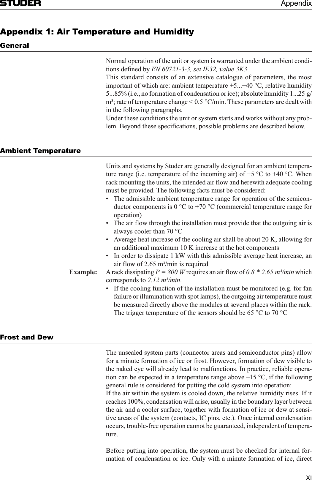
![Micro SeriesMicro Series 1-27Document generated: 04.10.17 SW V1.22.1.7 Meter ViewThe meter view shows the meter bargraphs of all input channels. Navigation is similar to navigating with the channel faders.12Pre Fader Signal Level Post Fader Signal Level [1] Label The label display shows the send channels name. This name can be entered in the Options page of the send channel. [2] OVL Indicator The overload indicator is used to indicate analogue input clipping (A/D con-verter), which means overload is never illuminated for digital sources. For channels with analogue inputs, OVL is illuminated as soon as the input level, before input calibration, reaches 0dBFS.[3] Mono Meter The meter of a mono input channel. The meter scale is digital with 0dBFS at the top. [4] Stereo Meter The meter of a stereo input channel. The meter scale is digital with 0dBFS at the top.Pre/Post level metering The level bargraph indicates pre- and post fader signal level at the same time.The pre fader signal level is indicated in the background as a blue bar. The post fader signal level is indicated in the foreground, covering the pre fader signal.](https://usermanual.wiki/Harman/MICROCORE/User-Guide-3749418-Page-44.png)
![Micro Series1-28 Micro Series Document generated: 04.10.17SW V1.22.1.8 Central SectionThe central section of the main page hosts the following control elements :12[1] On Air Red Light Indicator The On Air indicator is active when any of the input channels is on-air. [2] Settings A click or touch on this button leads to the Settings page where the basic configuration of the Micro Series is made.[3] View buttons The five view buttons allow to select the control elements that will be shown on the left section of the GUI.[4] Scroll buttons The scroll left and the scroll right button allow the operator to navigate to the desired faderstrips or meters.[5] Reset PFL This button releases any PFL button which is currently active anywhere in the mixer.](https://usermanual.wiki/Harman/MICROCORE/User-Guide-3749418-Page-45.png)
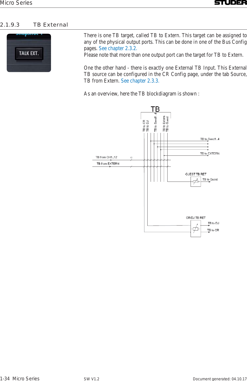
![Micro SeriesMicro Series 1-29Document generated: 04.10.17 SW V1.22.1.9 Right SectionThe right section of the main page hosts control elements for Watch, Record-ing, Snapshot handling, Metering and Monitoring.[][2][3][][][][][0][][][][][3][2][1] OnAir Watch The OnAir watch gives a permanent display of the current time and date. It can be NTP synchronized.[2] Fader Stopwatch The Fader stopwatch measures the channel-open time of the most recently opened channel that is “On-Master”. Only channels of the role “DJ”, “Guest” and “Input for Send” start the stopwatch. When clicking or touching onto the display of the stopwatch, a countdown time for the most recently opened channel can be entered. As soon as the time reaches 00:00:00, the channel name will flash for five seconds. If the time 00:00:00 is entered as a countdown time, the stopwatch will count upwards for as long as the channel is opened. The display of the stopwatch also indicates the name of the currently mea-sured channel. When in countdown mode, the countdown icon in the top right corner of the display is shown.[3] Recorder As a default, the REC bus is feeding the USB Recorder. So all channels that are assigned to the REC bus are recorded as soon as a valid memory stick is inserted and the record button is pressed. Details see chapter 2.1.9.1.[4] User Snapshots The User Snapshot considers the fact that the Micro Series are designed as](https://usermanual.wiki/Harman/MICROCORE/User-Guide-3749418-Page-46.png)
![Micro Series1-30 Micro Series Document generated: 04.10.17SW V1.2a portable products to be used in different environments. Therefore the User Snapshot contains all required settings of a broadcast session. User Snapshots can be created, saved, loaded, renamed and deleted by the user at any time.Details see chapter 2.1.9.2.[5] Talk Ext. This button activates the external talkback. TB source and destination can be configured. Details see chapter 2.1.9.3.[6] Program meter The Program meter is displaying the audio level of the Program bus. The headroom level and balistics can be configured. Details see chapter 2.4 - Meter tab.[7] CR Monitor meter The Monitor meter is displaying the audio level of the source which is cur-rently chosen by the CR monitor. The headroom level and balistics can be configured. Details see chapter 2.4 - Meter tab.[8] Monitor Cut This button lets the operator manually cut the CR monitor. In addition, CR cut is applied automatically when a channel of the role “DJ” or “Guest” gets on-air.[9] CR Monitoring Options This button opens the dialog to set the CR Monitoring Options. Details see chapter 2.2.5.[10] Guest Monitoring Options This button opens the dialog to set the Guest Monitoring Options. Details see chapter 2.2.6.[11] Source displays These three displays show the sources of the three different monitoring facili-ties.[12] CR Speaker level Lets the operator set the level of the CR monitor speakers[13] CR Headphone level Lets the operator set the level of the CR headphones[14] Guest Headphone level Lets the operator set the level of the Guest headphones2.1.9.1 USB Recorder12 At the moment an USB media is inserted into the Play/Rec USB port, a per-formance test of the media is carried out. When the media’s performance is sufficient, the LED next to the Play/Rec USB port turns green.[1] Status Indication With a valid USB media inserted, this display shows the amount of free memory of the inserted USB media. Below the free memory, the total amount of the inserted media’s memory is shown in [GB].Then, there is a progress-bar indicating the used memory of the USB storage media. Within the prog-ress bar, the predicted remaining recording time is displayed in the format hh:mm:ss.[2] Recording buffer This thin bar shows the current usage of the recording buffer.](https://usermanual.wiki/Harman/MICROCORE/User-Guide-3749418-Page-47.png)
![Micro SeriesMicro Series 1-31Document generated: 04.10.17 SW V1.2[3] Record Button Starts the recording. When the recording is on pause, another click/touch onto the Record Button restarts the recording and appends the recorded audio to the current file.While recording, the Status Indication display shows the name of the cur-rently recorded file and the files current length.[4] Pause/Stop Button A click/touch on this button pauses the recording. A second click/touch onto this button stops the recording and the recorded audio is written to a file. Where are the files stored ? By default, the recorded files are saved to the USB media into a folder auto-matically created, named ‘Recordings’.The files are also named automatically by the system. Time and date at the start of the recording determine the file name : yyyymmdd-hhmmss.wav.Record Source Selection The default source of the USB recorder is the REC bus. If desired, any other bus can be assigned as the recording source. This can be set on the Bus options page.Off-Air Record Function Off Air Record is a convenient function for the operator to record a guest or telephone interview in parallel to the program, where e.g. the radio automa-tion or a playlist from the track player is playing.The Off Air Record function handles all required bus assignments changes of the recording channels automatically in the background and the operator doesn’t have to care about.Scenario guest interview : The operator wants to record a guest interview where he needs the DJ mic and a guest mic. Activating the Off Air Record function (REC) of the DJ- and guest mic automatically as long as Off Air Record is active.When terminating Off Air Record, the original monitoring sources and bus assignments as defined in the channel- or bus options pages are restored.](https://usermanual.wiki/Harman/MICROCORE/User-Guide-3749418-Page-48.png)
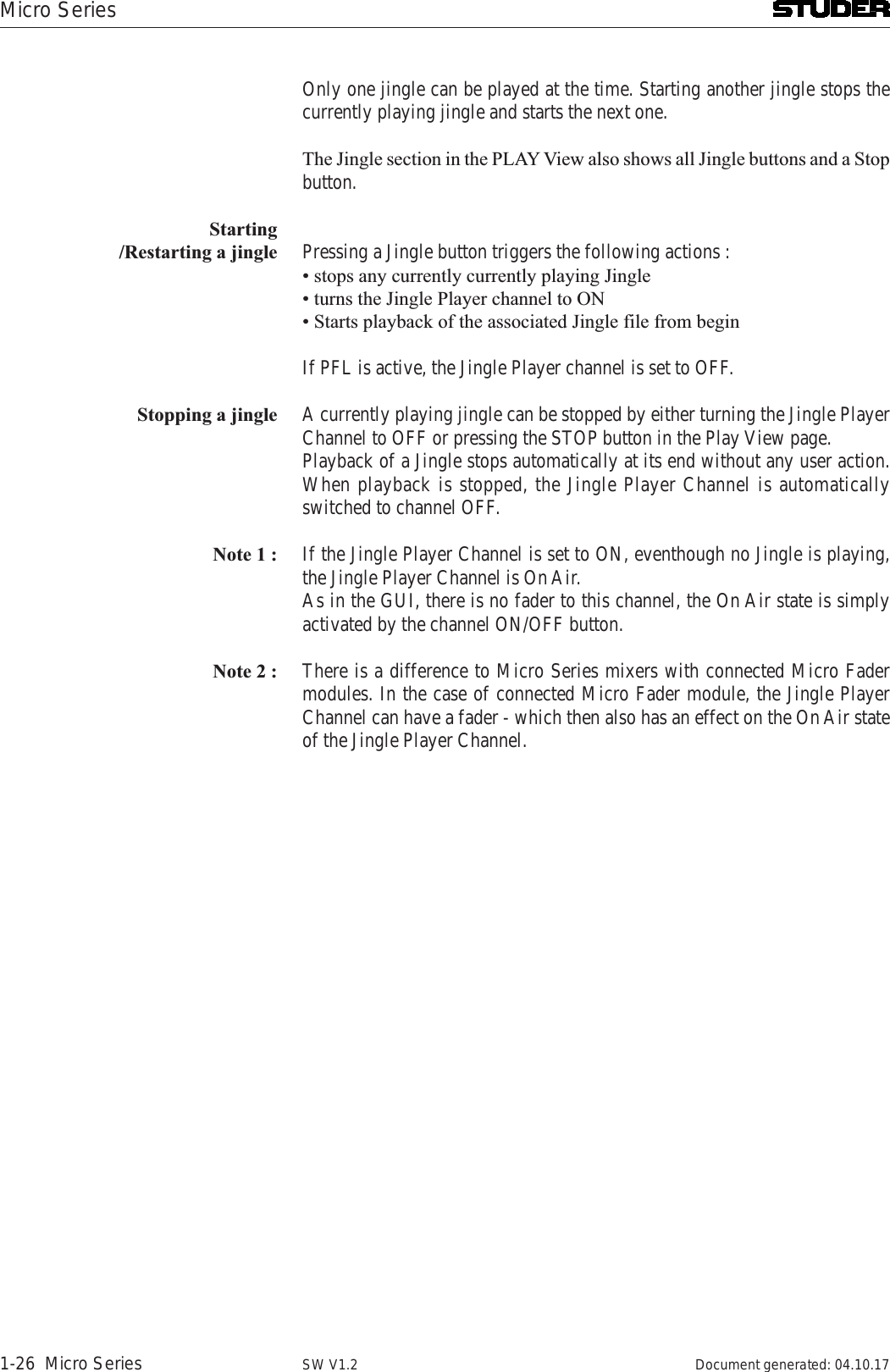
![Micro Series1-32 Micro Series Document generated: 04.10.17SW V1.22.1.9.2 User SnapshotsA User Snapshot contains all parameters of the system, except from the parameters of the Settings section.By Clicking/touching the Snapshot button, the snapshot options window opens and allows to load or save snapshots.With the buttons on the right side, snapshots can also be renamed or deleted.12[1] Load Recalls the selected User Snapshot and applies all parameters to the Micro Core where channels that are currently OnAir are not affected. The button is greyed out if no User Snapshot is selected.[2] Save Overwrites the currently selected User Snapshot. The button is greyed out if no User Snapshot is selected.[3] New Creates a new User Snapshot capturing all parameters . A dialog opens asking the user for a name for the new User Snapshot. If this name is already used, the user has to confirm overwriting this snapshot in a further dialog[4] Rename Renames the selected User Snapshot. The button is greyed out if no User Snapshot is selected. A dialog opens asking the user for a new name. [5] Delete Deletes the selected User Snapshot.Pending Channels A channel that is On-Master cannot be overwritten by a User Snapshot. Such a channel that should be updated from he snapshot, but is currently OnAir or On-Master is called a pending channel.Only after this channels fader is closed, or after deassigning it from the master bus, the channels parameter are overwritten by the User Snapshot.As soon as such a pending channel is no longer on a master bus, channel parameters of the most recently loaded User Snapshot are applied to that channel. This covers the case where subsequent User Snapshots are loaded while channels are still pending and makes sure that the most recently loaded User Snapshot is consistent. Pending channels are indicated to the user in different ways: -](https://usermanual.wiki/Harman/MICROCORE/User-Guide-3749418-Page-49.png)
![Micro SeriesMicro Series 1-35Document generated: 04.10.17 SW V1.22.2 L2 - The options level2.2.1 Channel optionsChannel options are entered by doubleclicking or touching the channel label[] [][][][][2][3][][1] Icon and Name Double-clicking on the name field allows the operator to enter a new channel name. The icon is automatically chosen, depending on the channel role.[2] Auto Cal Touching the AUTO CAL button starts the Automatic Gain Calibration process. During the process the AUTO CAL button is flashing and the user is able to see the calibration process on the channel meter. The calibration process can be interrupted manually by touching the AUTO CAL button again. During the calibration process, the input signal is analyzed and the analogue input gain is adjusted automatically to reach the optimal mic/line input level. The calibration is depending on the headroom setting in the meter configuration section.The Automatic Gain Calibration function is provided for all HQ Mic/Line channels.[3] Channel processing On/Off The channel processing On/Off buttons (DeEsser, HP, EQ, LP, Comp, Gate) activate and deactivate the chosen processing block.](https://usermanual.wiki/Harman/MICROCORE/User-Guide-3749418-Page-52.png)
![Micro Series1-36 Micro Series Document generated: 04.10.17SW V1.2[4] Pan On/Off The Pan On/Off button activates and deactivates the panning section.[5] Bus assign buttons These buttons assign the input channel to the desired busses.[6] Config button Pressing this button opens the configuration page of the current channel. There, the detailed channel configuration can be carried out, such as EQ parameter setting, Dynamics parameter setting, etc..Details see chapter 2.3.[7] Back to operation view Clicking or touching onto the area in the top right corner navigates back to the operation view.[8] Navigation Navigation to the option pages of other channels is provided on the bottom channel navigation bar.On channels of the role “Input for send”, there is an additional control element:1[1] Send signal and Send level For “Input for send”- channels, on the channel options page also the bus for the send signal, as well as its level can be chosen. “Input for send” - channels are in other terms the N-1 bus owner channel. The send signal can then be called the N-1 mix or the mix-minus signal.The send level can also be set on the channel send view.](https://usermanual.wiki/Harman/MICROCORE/User-Guide-3749418-Page-53.png)
![Micro SeriesMicro Series 1-37Document generated: 04.10.17 SW V1.2On channels of the role “Player”, there are two additional control elements : 12[1] Player Mode Automatic or Manual. This settings is the same as the mode setting in the player view.[2] Media Media and playlist selectionClicking or touching onto the Media field, opens up the media dialog.This list shows : A playlist or an audio file can be selected.The following externally created playlists are supported :File Extension Description.wpl Windows Media Player Playlist.m3u Multimedia Playlist.pla Winamp Playlist.pls Text Based Multimedia PlaylistAnd the following audio fime formats are supported :Format File E tension DescriptionWave .wav uncompressed audioAAC .aac lossy audio compressionMP3 .mp3 lossy audio compressionOgg Vorbis .ogg lossy audio compressionAIFF .aif uncompressed audioFLAC .flac lossless audio compression](https://usermanual.wiki/Harman/MICROCORE/User-Guide-3749418-Page-54.png)
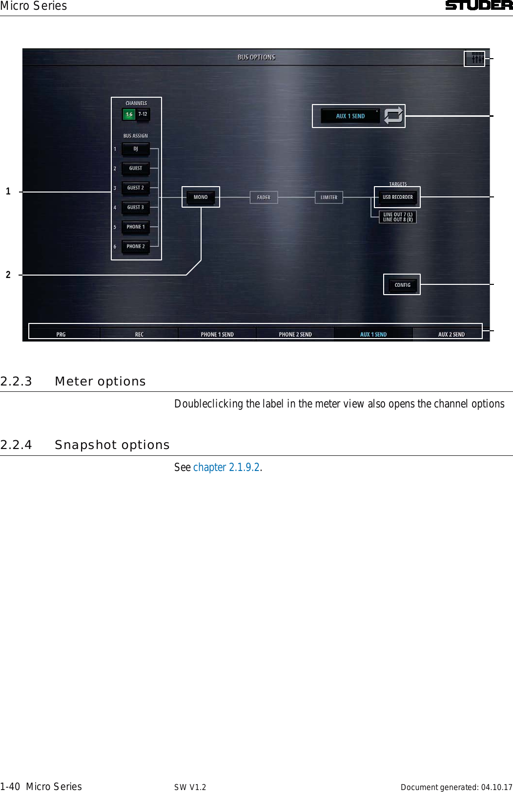
![Micro Series1-38 Micro Series Document generated: 04.10.17SW V1.22.2.2 Bus optionsBus options are entered by doubleclicking or touching the send or bus labelwhen in send or bus view12[1] Bus assign Bus assign (for Sum and Aux busses) allows to assign all of the input chan-nels to the currently viewed bus.[2] Mono TheMono button mixes down the stereo signal to a mono signal and assigns this signal to both, the Left and the Right leg of the stereo bus.[3] Icon and Name Double-clicking on the name field allows the operator to enter a new bus name. The icon is automatically chosen, depending on the bus type and bus mode (Aux / N-1).[4] USB Recorder Per default, the USB recorder is patched to the REC bus. If there is the need, the USB recorder can be patched to any of the busses (Sum, N-1, Aux). There is only one USB recorder available, which implies that it can only be patched to one of the busses at the time.[5] Config Config button. Pressing this button opens the configuration page of the current bus. There, patching to outputs as well as chosing the bus mode and setting the send levels can be done. Details see chapter 2.3.](https://usermanual.wiki/Harman/MICROCORE/User-Guide-3749418-Page-55.png)
![Micro SeriesMicro Series 1-39Document generated: 04.10.17 SW V1.2[7] Back to operation view Clicking or touching onto the area in the top right corner navigates back to the operation view.[8] Navigation Navigation to the option pages of other busses is provided on the bottom channel navigation bar.The options page of the N-1 busses differs only in the source selection:12[1] Source Send signal Prg or Rec (for N-1 busses)The options page of the Aux busses has the same bus asign buttons as the Sum busses.](https://usermanual.wiki/Harman/MICROCORE/User-Guide-3749418-Page-56.png)
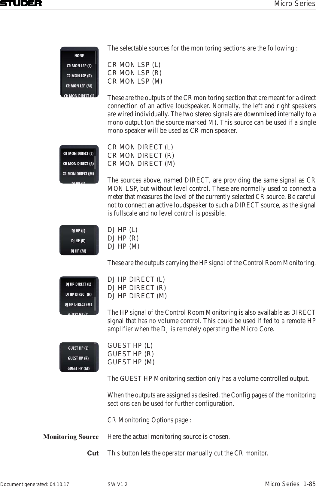
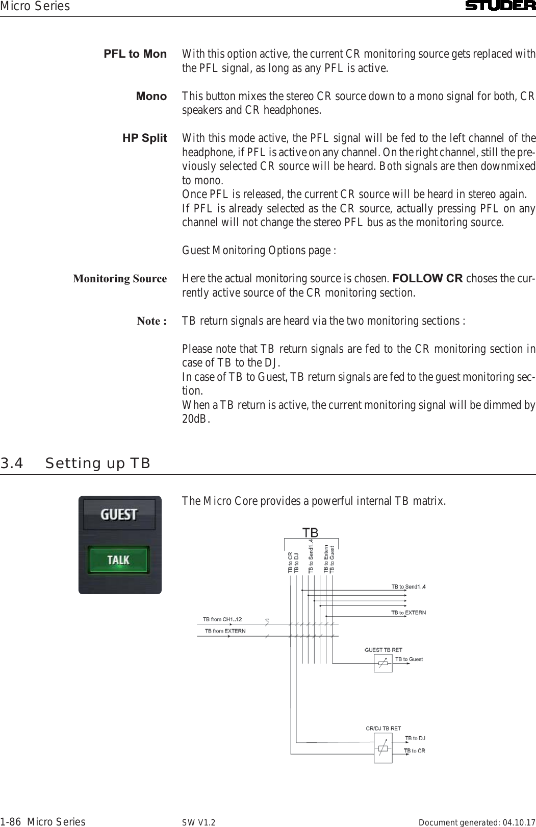
![Micro SeriesMicro Series 1-41Document generated: 04.10.17 SW V1.22.2.5 CR Monitoring optionsBy clicking/touching the CR Monitoring Options button, the CR monitor-ing panel is shown :12[1] CR monitoring source selector With these buttons the source for the control room monitoring is chosen. The source is the same for the CR speakers and the CR headphones. The selected source is displayed on the source displays[2] Monitor Cut This button lets the operator manually cut the CR monitor.[3] PFL to Mon With this option active, the current CR monitoring source gets replaced with the PFL signal, as long as any PFL is active.[4] Mono This button mixes the stereo CR source down to a mono signal for both, CR speakers and CR headphones.[5] Headphones Split Mode With this mode active, the PFL signal will be fed to the left channel of the headphone, if PFL is active on any channel. On the right channel, still the pre-viously selected CR source will be heard. Both signals are then downmixed to mono.Once PFL is released, the current CR source will be heard in stereo again.If PFL is already selected as the CR source, actually pressing PFL on any channel will not change the stereo PFL bus as the monitoring source.[6] TB return level This rotary controls the incoming TB signal level which is fed to the CR speakers as well as to the CR headphones. Please note that the current CR source signal is then dimmed by 20dB.](https://usermanual.wiki/Harman/MICROCORE/User-Guide-3749418-Page-58.png)
![Micro Series1-42 Micro Series Document generated: 04.10.17SW V1.2[7] CR speaker level This rotary controls the level of the CR speakers.[8] CR headphones level This rotary controls the level of the CR headphones.[9] Config button This button navigates to the CR monitoring config page.2.2.6 Guest Monitoring optionsBy clicking/touching the Guest Monitoring Options button, the guest monitoring panel is shown :[] [3][2][][1] Monitoring source selector With these buttons the source for the guest monitoring is chosen. The selected source is displayed on the source display.[2] Follow CR This button selects the same source as currently active on the CR monitoring section.[3] Guest headphones level This rotary controls the level of the Guest headphones.[4] TB return level This rotary controls the incoming TB signal level which is fed to the Guest headphones. Please note that the current Guest monitoring source signal is then dimmed by 20dB.](https://usermanual.wiki/Harman/MICROCORE/User-Guide-3749418-Page-59.png)
![Micro SeriesMicro Series 1-43Document generated: 04.10.17 SW V1.22.3 L3 - The configuration level2.3.1 Channel configClicking/touching the Config button in the channel options view allows access to the channel config page. Six processing block selection tabs navi-gate to a channels different processing sections.The config page of the channels source section holds control elements nece-sarry to set the channels source selection.12[1] Processing tabs These tabs lets the operator navigate to the desired processing block of achannel.[2] Source selection With these two pull-down menues, the source for the left channel leg, and the source for the right channel leg can be selected. If for the right channel leg the selection remains on “None”, then the channel is a mono channel. An exception are the sources “USB” and “AES” - these sources are always stereo sources and are only selected on the first pull-down menu.[3] Channel role Here the role of the channel is defined. The choice is as follows :Default - for a simple input channel, no special behaviourDJ - for a mic source located in the control room (CR)Guest - for a mic source located in the control room (CR)Input for send 1 - the bus owner of a N-1 busInput for send 2 - the bus owner of a N-1 busInput for send 3 - the bus owner of a N-1 busInput for send 4 - the bus owner of a N-1 bus](https://usermanual.wiki/Harman/MICROCORE/User-Guide-3749418-Page-60.png)
![Micro Series1-44 Micro Series Document generated: 04.10.17SW V1.2JingleTrackDepending on the channel role, the channels control elements on the GUI are different.[4] Test tone With these two buttons. test tone can be fed to the left and the right leg of the channel. The test tone signal is defined in the “Settings”-page[5] Navigation back. Clicking or touching onto this area navigates back to the Options page of this channel.[6] Back to operation view Clicking or touching onto the area in the top right corner navigates back to the operation view.[7] Navigation to other channels Navigation to the config pages of other channels is provided on the bottom channel navigation bar.](https://usermanual.wiki/Harman/MICROCORE/User-Guide-3749418-Page-61.png)
![Micro SeriesMicro Series 1-45Document generated: 04.10.17 SW V1.2The config page of the channels input section holds control elements necesarry to set the channels input levels :12If the channels source selection is a Mic source, then these three elements are provided on the left side of the page.[1] 48V Switches phantom power (48V) to the microphone on and off.[2] Highpass filter Activates a highpass filter on the analog side of the microphone input, before theA/D converter. This can be useful to filter out rumbling noise on speach signals. The cutoff frequency of this filter is fixed at 75Hz and it has a slope of 12dB/oct.[3] Mic gain This fader sets the microphone gain.The gain range is 86dB and the absolute numbers on the fader-scale are depending on the Max Level of the analog I/O. Max Level is defined in the Settings page.On channels with Line inputs as source, other control elements are displayed in place of the Mic control elements.Max Level The Max Level setting defines the systems reference line level for 0dBFS. This is a global setting found on the Settings-page. But it can also be set on a channel by channel basis. This setting needs to correspond with the actual level calibration of the analogue input- and output interfaces. As a standard, the Micro Core is shipped with all analogue levels calibrated to +9dBu. This means that the highest possible analog signal that leaves the mixer is +9dBu. And it also means, that signals which are higher than +9dBu will clip the A/D converters.Then, in the second section of this page, the control elements of the digital](https://usermanual.wiki/Harman/MICROCORE/User-Guide-3749418-Page-62.png)
![Micro Series1-46 Micro Series Document generated: 04.10.17SW V1.2processing are found.[4] Phase Inverts the mono signal or the left channel of the stereo signal if turned On.[5] Input calibration This fader allows the operator to trim the signal by +/-18dBOn stereo channels, in this section also a Mono button can be found. This button downmixes the stereo signal to mono : Mono=(Left+Right)-3dB[6] Reset This button sets all values of this processing block to the default values. Please note that this button can be found on every tab of the channel config page.](https://usermanual.wiki/Harman/MICROCORE/User-Guide-3749418-Page-63.png)
![Micro SeriesMicro Series 1-47Document generated: 04.10.17 SW V1.2The config page of the channels de-esser section holds control elementsnecesarry to set the channels De-esser parameters :11211[1] DeEsser On/Off Activates the De-Esser when illuminated.[2] RTA A real time frequency analysis of the channels signal is computed and dis-played in the spectrum field of the De-Esser. This is a visual aid helping the operator to find the problematic areas of the channels signal.[3] Reverse The reverse function allows listening to the part of the signal which is going to be removed by the De-Esser.[4] Freq Sets the operation frequency of the De-Esser.[5] QSets the width of the bandpass filter.[6] Threshold Sets the threshold of the bandpass compressor.[7] Ratio Sets the ratio of the bandpass compressor.[8] Attenuation Controls the amount of gain reduction. Attenuation is only available when Auto is active.[9] Auto Enables automatic threshold, which dynamically adjusts the De-Esser thresh-old according to the incomming audio. When Auto is active, Ratio and Threshold controls are disabled in place of Attenuation.[10] Reset This button sets all values of this processing block to the default values. [11] Presets Opens the preset window for the De-Esser presets.](https://usermanual.wiki/Harman/MICROCORE/User-Guide-3749418-Page-64.png)
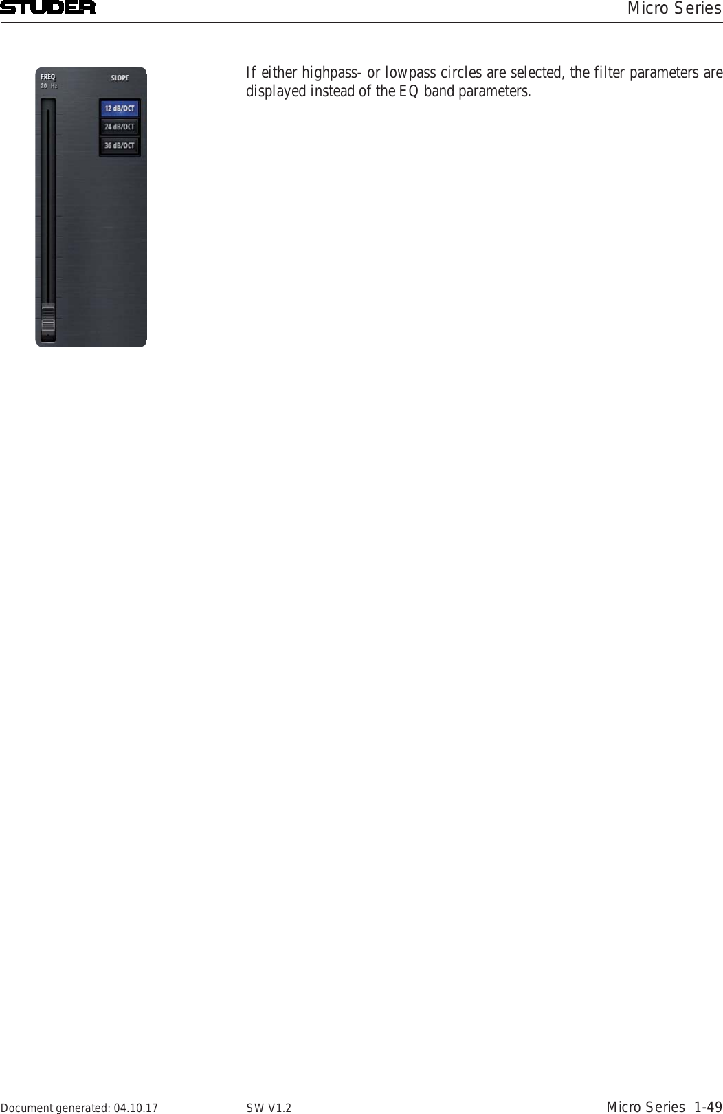
![Micro Series1-48 Micro Series Document generated: 04.10.17SW V1.2The config page of the channels eq section holds control elements necesarry to set the channels eq and high- and lowpassfilter :12[1] EQ On/Off Activates the EQ when illumnated.[2] Highpass filter On/Off Activates and deactivates the highpass filter.[3] Lowpass filter On/Off Activates and deactivates the lowpass filter.[4] RTA A real time frequency analysis of the channels signal is computed and dis-played in the spectrum field of the EQ. This is a visual aid helping the operator to find the problematic areas of the channels signal.[5] Freq Controls the frequency parameter of the selected EQ band. One of the four EQ bands can easily be selected by clicking or touching onto the numbered (1-4), coloured circles on the frequency axis.[6] QSets the width of the EQ band.[7] Gain Sets the gain (+/- 18dB) of the EQ band. [8] Reset This button sets all values of this processing block to the default values.[9] Presets Opens the presets window for EQ presets.The EQ can also completely be operated on the spectrum field - either by using mouse or touchscreen.](https://usermanual.wiki/Harman/MICROCORE/User-Guide-3749418-Page-65.png)
![Micro Series1-50 Micro Series Document generated: 04.10.17SW V1.2The config page of the channels dynamics section holds control elements necesarry to set the channels compressor and gate parameters :[][][2][][2][3] [][][][][] [0][1] Comp On/Off Activates the compressor when illuminated.[2] Gate On/Off Activates the gate when illuminated.[3] Comp/Gate Selects either the Comp- or the Gate view.[4] Threshold Sets the threshold parameter of the compressor. The lower the threshold, the more signal compression is achieved.[5] Ratio Sets the compression ratio parameter. A ratio of 1:1 doesn’t process the signal at all, a ratio of 3:1 is a medium compression, 5:1 a heavy compression and settings above 10:1 are called limiting.[6] Attack time Sets the attack time of the compressor. The shorter this attack time is, the quicker a gain reduction is applied to the signal.[7] Release time Sets the release time of the compressor. The longer this release time is, the longer it takes until the gain reduction is released and the signal becomes unprocessed again.[8] Gain Sets the makeup gain of the compressor. This is a simply signal amplification stage that allows to bring the processed signal back to the desired level.[9] Auto This button overrules the Gain parameter and automatically applies as much makeup gain as needed to make the processed output signal as loud as the](https://usermanual.wiki/Harman/MICROCORE/User-Guide-3749418-Page-67.png)
![Micro SeriesMicro Series 1-51Document generated: 04.10.17 SW V1.2unprocessed input signal.[10] Softknee Sets the Softknee mode On and Off. The activated Softknee mode softens the transition area around the threshold value. [11] Reset This button sets all values of this processing block to the default values.[12] Presets Opens the presets window for Compressor presetsHere, the gate view is shown :12[1] Comp On/Off Activates the compressor when illuminated.[2] Gate On/Off Activates the gate when illuminated.[3] Comp/Gate Selects either the Comp- or the Gate view.[4] Threshold Sets the threshold parameter of the gate. With a low threshold, the noise gate will open up already for very small signals. With a higher threshold, only larger signals will trigger the noise gate to open up.[5] Attack time Sets the attack time of the gate. The shorter this attack time is, the quicker the noise gate opens up.[6] Release time Sets the release time of the gate. The longer this release time is, the longer it takes until the noise gate is closed again.[7] Attenuation Sets the attenuation parameter of the gate. To make the noise gate completely](https://usermanual.wiki/Harman/MICROCORE/User-Guide-3749418-Page-68.png)
![Micro Series1-52 Micro Series Document generated: 04.10.17SW V1.2blocking a signal, the attenuation must be a large value. If the attenuation is left at 0dB, the noise gate has no influence at all.[8] Reset This button sets all values of this processing block to the default values.[9] Presets Opens the presets window for Gate presets](https://usermanual.wiki/Harman/MICROCORE/User-Guide-3749418-Page-69.png)
![Micro SeriesMicro Series 1-53Document generated: 04.10.17 SW V1.2The config page of the channels pan section holds control elements necesarry to set the channels panning/balance :12Pan/Bal depending wether mono or stereo channels[1] Pan/Bal On/Off Activates the panner when illuminated.[2] Pan/Bal Positions the signal between the left and the right leg of all stereo busses itis assigned to.[3] Reset This button sets all values of this processing block to the default values.](https://usermanual.wiki/Harman/MICROCORE/User-Guide-3749418-Page-70.png)
![Micro Series1-54 Micro Series Document generated: 04.10.17SW V1.2The config page of the channels send section holds control elements necesarry to set the channels send levels :12[1] Send levels These are the send levels of all input channels. Since the input channels are fed “post-fader” to the send bus, these send levels can be regarded as a trim function. Please note that the channel that we are currently configuring cannot be sent to its own send bus (N-1 concept, also called mix-minus) .[2] Master Send level Sets the output level of the send bus.[3] On/Off Switches the output signal of the send bus on and off.[4] Reset Resets all parameters.2.3.2 Bus ConfigClicking/touching the Config button in the bus options view allows access to the bus config page. Two or three selection tabs navigate to the different sections. PRG and REC busses have the tabs Targets and Outputs. All other busses have Send, Targets and Outputs tabs.](https://usermanual.wiki/Harman/MICROCORE/User-Guide-3749418-Page-71.png)
![Micro SeriesMicro Series 1-55Document generated: 04.10.17 SW V1.2The config page of the busses Target section holds control elements necesarry to assign mixer internal sources to the output ports.12[1] Line Out Here, the sources for the 12 Line Out output ports can be assigned. This is done by clicking/touching on the source. A choice of all possible sources appears in a list where simply the desired source can be selected. There are sources that are marked (L) or (R) or (M). As Line Out ports are mono, only mono sources can be selected, (L) stands for the left leg of a stereo source, (R) stands for the right leg of a stereo source, and (M) is the stereo source downmixed to mono.[2] Dante Out Here, the sources for the eight Dante Out output ports can be assigned.[3] AES Out Here, the sources for the two stereo AES Out output ports can be assigned.[4] Unbalanced Jack Here, the sources for the two stereo headphone output ports can be assigned.[5] Navigation to other busses Navigation to the config pages of other busses is provided on the bottom bus navigation bar.Note : Please note, that this view is the same for all six busses ! The output assignment can only be made once for each output port.](https://usermanual.wiki/Harman/MICROCORE/User-Guide-3749418-Page-72.png)
![Micro Series1-56 Micro Series Document generated: 04.10.17SW V1.2The config page of the busses Output section holds control elements necesarry to calibrate the levels of the analog output ports.1[1] Line Out Here, the Max Level of the 12 Line Out output ports can be selected. This setting defines the analog signal level for the highest possible internal signal of 0dBFS. It can set for each Line Out individually.Note : Please note, that this view is the same for all six busses ! On the Settings page under the tab Audio, this setting can be made globally for all analog input- and output ports at once.](https://usermanual.wiki/Harman/MICROCORE/User-Guide-3749418-Page-73.png)
![Micro SeriesMicro Series 1-57Document generated: 04.10.17 SW V1.2The config page of the N-1 busses Send section holds control elements necesarry to set the actual send levels of contributing channels - e.g. to set the mix.[][][2][3][][1] Send levels These are the send levels of all input channels to the currrently chosen bus.Please note that the channel that we are currently configuring cannot be sent to its own send bus (N-1 concept, also called mix-minus) .[2] Master Send level Sets the output level of the send bus.[3] On/Off Switches the output signal of the send bus on and off.[4] Bus Mode Lets the user select the bus mode that can either be N-1 or Aux.N-1 : this mode is made for busses that are feeding a return signal to remote positions. This mode doesn’t allow the input signal of the remote source to be assigned to the bus. With this bus mode, the remote source (e.g. a reporter) will never have his own signal in his return feed. This is opti-mal to prevent echo’s that could be introduced through long distance signal transmission.Aux : this is the bus mode that allows all sources to be assigned to the bus . The user can decide whether the signal should be sent to the bus eitherbefore or after the channals fader. This can be set for each source individually by chosing Pre or Post with the button on the top. Also each source has an individual on/off button to select the desired bus assign (see image below). [5] Reset Resets all parameters.](https://usermanual.wiki/Harman/MICROCORE/User-Guide-3749418-Page-74.png)
![Micro Series1-58 Micro Series Document generated: 04.10.17SW V1.2The config page of the AUX busses Send section holds control elements necesarry to set the actual send levels of contributing channels - e.g. to set the mix.21[1] Pre/Post Lets the user decide whether the signal should be sent to the Aux bus either before or after the channals fader. “Pre” stands for before the fader, “Post”stands for after the fader.[2] Send levels These are the send levels of all input channels to the currrently chosen bus.[3] Send On/Off Each source has an individual On/Off button to assign the channel to the Aux bus.[5] Master Send level Sets the output level of the send bus.[4] On/Off Switches the output signal of the send bus on and off.[6] Bus Mode Lets the user select the bus mode that can either be N-1 or Aux.N-1 : this mode is made for busses that are feeding a return signal to remote positions. This mode doesn’t allow the input signal of the remote source to be assigned to the bus. With this bus mode, the remote source (e.g. a reporter) will never have his own signal in his return feed. This is opti-mal to prevent echo’s that could be introduced through long distance signal transmission.Aux : this is the bus mode that allows all sources to be assigned to the bus . The user can decide whether the signal should be sent to the bus eitherbefore or after the channals fader. This can be set for each source individually by chosing Pre or Post with the button on the top. Also each source has an individual on/off button to select the desired bus assign. [7] Reset Resets all parameters.](https://usermanual.wiki/Harman/MICROCORE/User-Guide-3749418-Page-75.png)
![Micro SeriesMicro Series 1-59Document generated: 04.10.17 SW V1.22.3.3 CR Monitoring ConfigClicking/touching the Config button in the CR Monitoring options view allows access to the CR config page. Five selection tabs navigate to the dif-ferent sections.The config page of the Source section holds control elements necesarry to selecte a source for two different purposes.12[1] Source Here, a mono or stereo source can be chosen for two different purposes :External Monitoring Source TB from ExternDepending on the selected tab :[2] External Monitoring Source The signal that is selected here becomes the external monitoring source. It will be active on the CR monitor when the corresponding button is pressed.](https://usermanual.wiki/Harman/MICROCORE/User-Guide-3749418-Page-76.png)
![Micro Series1-60 Micro Series Document generated: 04.10.17SW V1.2[3] TB from Extern Allows to define the input port, where the external TB returns into the Micro Core. This is the return signal of the external TB circuit. The send signal (TB to Extern) can be defined in the Target tab.](https://usermanual.wiki/Harman/MICROCORE/User-Guide-3749418-Page-77.png)
![Micro SeriesMicro Series 1-61Document generated: 04.10.17 SW V1.2On the Input tab of the CR Config page, the input parameters of the two selected source-signals can be set.12[1] Phase If the selected source signal is a stereo signal, the Phase button is available. This button inverts the phase of the left chanel.[2] Mono Also for stereo sources - the Mono button mixes down the stereo signal to a mono signal.[3] Input Calibration The Cal fader allows to calibrate the signal within a range of +/- 18dB.[4] Reset This button sets all values of this processing block to the default values.If the channels source selection is a Mic source, then three more elements are provided on the left side of the page. These are :48VHighpass FilterMic GainOn channels with Line inputs as source, other control elements are displayed in place of the Mic control elements.Max Level The Max Level setting defines the systems reference line level for 0dBFS. This is a global setting found on the Settings-page. But it can also be set on a channel by channel basis. This setting needs to correspond with the actual level calibration of the analogue input- and output interfaces. As a standard, the Micro Core is shipped with all analogue levels calibrated to +9dBu. This means that the highest possible analog signal that leaves the mixer is +9dBu. And it also means, that signals which are higher than +9dBu will clip the A/D converters.](https://usermanual.wiki/Harman/MICROCORE/User-Guide-3749418-Page-78.png)
![Micro Series1-62 Micro Series Document generated: 04.10.17SW V1.2The CR EQ tab displays a graphic equalizer (GEQ) that is inserted into the CRMON LSP signal path. It can be used to flatten undesired room resonances of the control room. 1[2][][][3][][][1] CR EQ Activates the GEQ when illuminated.[2] Left side This area displays an overview icon of the left side portion of the GEQ. Click-ing/touching onto this area allows to operate the 32 bands of the GEQ in the large window below. [3] Link/Unlink Clicking/touching onto this area unlinks the left- and the right side of the GEQ. As a default, the left and right side are linked, allowing to control either side of the GEQ while the parameters of the other side automatically are set to the same values.Please note that when linking both sides, always the current setting of the left side GEQ is taken and applied to both sides.[4] Right side This area displays an overview icon of the right side portion of the GEQ. Clicking/touching onto this area allows to operate the 32 bands of the GEQ in the large window below.[5] GEQ bands These are the actual GEQ bands that can be used to set the desired band values in a range of +/- 15dB. Clicking/touching and dragging at the same time slides the bands up or down.](https://usermanual.wiki/Harman/MICROCORE/User-Guide-3749418-Page-79.png)
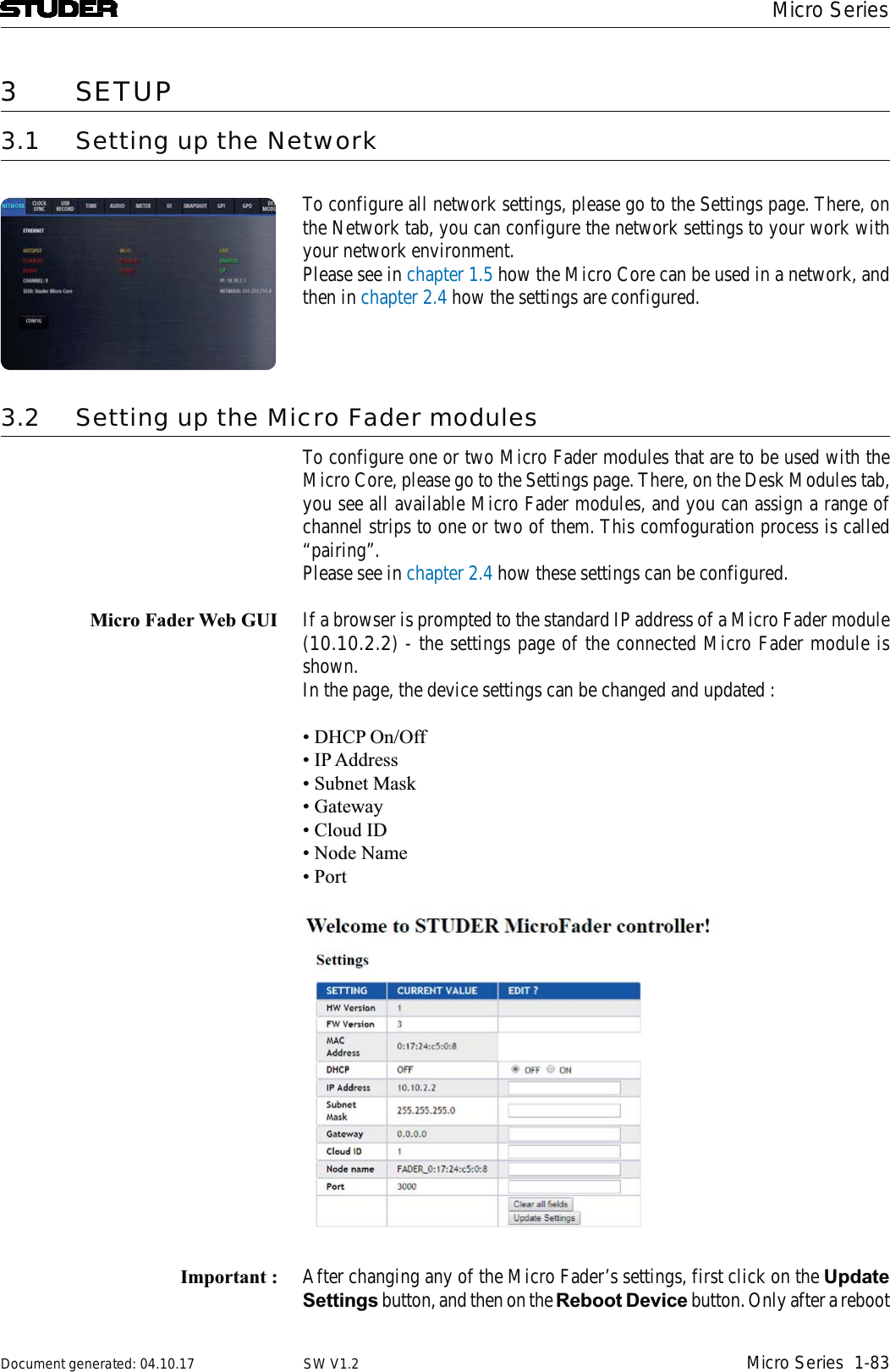
![Micro SeriesMicro Series 1-63Document generated: 04.10.17 SW V1.2[6] RTA A real time frequency analysis of a selectable signal is computed and displayed in the spectrum field of the GEQ. This is a visual aid helping the operator to find the problematic areas of a specific source.[7] RTA Source This is the source selector for the signal that is fed into the RTA.[8] Presets Opens the presets window for GEQ presets..[9] Reset This button flattens and deactivates the GEQ.The Targets- and Outputs tabs are the same pages as also shown in the bus config pages.2.4 Settings viewA click or touch onto the Settings button leads to the Settings page where the basic configuration of the Micro Core is made.On the Network tab, the network configuration can be made and the current status of the network is displayed.](https://usermanual.wiki/Harman/MICROCORE/User-Guide-3749418-Page-80.png)
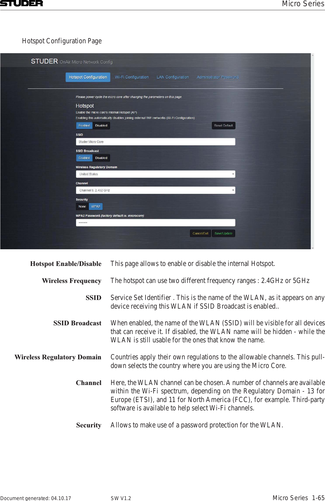
![Micro Series1-64 Micro Series Document generated: 04.10.17SW V1.2On the Network tab, the network states are shown and the network can be configured.12[1] Hotspot status display Here the current status of the internal Hotspot is shown.The base unit of the OnAir Micro is able to produce its own WLAN, or with other words, it has its own Wireless Access Point (WAP). When the Hotspot is enabled, the Wi-Fi is automatically disabled and vice versa.[2] Wi-Fi status display This section shows the current state of the Wi-Fi section. When the Wi-Fi is enabled, the Hotspot is automatically disabled and vice versa.[3] Ethernet status display Here the current settings of the wired Ethernet port are shown. The Ethernet port can be used while Hotspot/Wi-Fi access is also active.[4] Config button By pressing this button, the network configuration pages are opened. The Config logon window appears, and the following password need to be entered :Password : admin](https://usermanual.wiki/Harman/MICROCORE/User-Guide-3749418-Page-81.png)
![Micro SeriesMicro Series 1-69Document generated: 04.10.17 SW V1.2On the Clock Sync tab, the sampling rate as well as the sync options can be found.12[1] Sampling Rate Sets the sampling rate to either 44.1kHz or 48 kHz.[2] Preferred Sync Source selection The mixer’s preferred sync source can be chosen here. As the standard, the internal sync generator is used. If desired, the mixer can be synchronised to the clock received on either the Wordclock-, or one of the AES inputs. The Source State indicators then show the state of each possible sync source.The sync logic makes sure that the preferred sync source becomes active if there is a valid signal with the desired sampling rate. If the preferred sync source is not valid, the sync logic switches to the internal sync generator.[3] Sync State This is the display of the current sync source. If e.g. the selected sampling rate is 48kHz and word clock is the selected Sync Source, but the external word clock provides 44.1kHz or is even not available, the Sync State will indicate INTERNAL, as the sync logic defaults to internal clock generator running on the selected sampling rate.](https://usermanual.wiki/Harman/MICROCORE/User-Guide-3749418-Page-86.png)
![Micro Series1-70 Micro Series Document generated: 04.10.17SW V1.2On the USB Record tab, all necesarry parameters for the USB recording can be set.12[1] Folder In this window all recorded files that are found on the USB media are shown. The folder where the recorded files are stored is called “Recordings”. If there is no such a folder on the USB media, it will be created automatically. Also, recorded files can be renamed or deleted.[2] Format Selects the file format of the recordings.WAV Linear, uncompressed audio file.FLAC Lossless compressed audio file.[3] Format USB This button allows to format the inserted USB media with the FAT-32 file system format. All data on the USB media will then be deleted.](https://usermanual.wiki/Harman/MICROCORE/User-Guide-3749418-Page-87.png)
![Micro SeriesMicro Series 1-71Document generated: 04.10.17 SW V1.2The Time tab hosts all controls to set the time settings of the mixer.[] [][2][3][1] Time Reference Allows to select either an external NTP or the internal time reference. If NTP is selected, an additional field appears where the address of the NTP time server can be specified.[2] Time Zone Selects the UTC time zone.[3] Daylight Saving Allows to switch daylight saving either on or off. Daylight saving is active when the button is illuminated.[4] New Time Allows the operator to adjust the time and date.New Date](https://usermanual.wiki/Harman/MICROCORE/User-Guide-3749418-Page-88.png)
![Micro Series1-72 Micro Series Document generated: 04.10.17SW V1.2The Audio tab has controls for the PFL mode, internal test tone generator, setting of the analog I/O ports, TB cut and console initialisation.12[1] CUE/PFL Selects the PFL behaviour. CUE mode lets the operator listen to the post-fader signals. PFL is pre-fader-listening.[2] Generator Shape Allows the operator to select either a sine-wave, pink noise or white noise as the test tone signal.[3] Frequency This fader controls the sine-wave-generators frequency. The possible fre-quency range is from 20Hz to 20kHz.[4] Level The level fader controls the test tone level. It ranges from -infinity to 0dBFS.[5] Max Level The Max Level setting defines the systems reference line level for 0dBFS. This is a global setting. But it can also be set on a channel by channel basis. This setting needs to correspond with the actual level calibration of the ana-logue input- and output interfaces. As a standard, the Micro Core is shipped with all analogue levels calibrated to +9dBu. This means that the highest possible analog signal that leaves the mixer is +9dBu. And it also means, that signals which are higher than +9dBu will clip the A/D converters.[6] Init Console The Init button resets all mic gain values in reference to the seleted Max Levelsetting.[7] TB Mic Cut TB Mic Cut is a security feature to prevent a TB signal from going on-air. The TB Mic Cut function can be activated/deactivated here. As soon as the TB is activated to anywhere, the associated channel will be cut pre-fader.This is valid for channels of role DJ, Guest, Input for Send 1..4.](https://usermanual.wiki/Harman/MICROCORE/User-Guide-3749418-Page-89.png)
![Micro SeriesMicro Series 1-73Document generated: 04.10.17 SW V1.2On the Meter tab, the parameters of the mixer internal metering can be set.12[1] Headroom Sets the top, red area of the meter. The default value is 9dB, this means that meter values above -9dBFS are then displayed in red meter bar elements.[2] Operation Range This is the mid section of the meter where the signal is displayed in green meter bar elements. Meter bar elements below the operation range are yellow.[3] Integration Time Sets the meters integration time.None 0 msFast 1 msIEC Type I 5 msIEC Type II 10 ms](https://usermanual.wiki/Harman/MICROCORE/User-Guide-3749418-Page-90.png)
![Micro Series1-74 Micro Series Document generated: 04.10.17SW V1.2The UI settings tab allows to switch the button assignment of the User Inter-face from default to US.The chosen mode is valid for the GUI as well as for the hardware Micro Fader module.1[1] Button Assignment Changes the button assignment mode.Default US](https://usermanual.wiki/Harman/MICROCORE/User-Guide-3749418-Page-91.png)
![Micro SeriesMicro Series 1-75Document generated: 04.10.17 SW V1.2The Snapshot tab allows to set snapshot recall options.1[1] Fader This button allows to protect all input channel faders from snapshot recall.Note : Please note that any channel fader that is On-Master, is protected from snap-shot recall anyway - irrespective of this setting.](https://usermanual.wiki/Harman/MICROCORE/User-Guide-3749418-Page-92.png)
![Micro Series1-76 Micro Series Document generated: 04.10.17SW V1.2The GPI tab is the page where all general purpose input functions are con-figured and activated.1[2] [3] [ ] [ ] [ ][1] On/Off Lets the operator activate the GPI. The button is illuminated when active.[2] Dir The Polarity of the signal at the input pin: High=Active is positive-, Low=Active is negative polarity.[3] Sensitivity Considering the polarity, the sensitivity defines whether the input function reacts on Rising edge, Falling edge or Level changes.[4] Action Action is only relevant, if sensitivity is falling edge or rising edge. In this case,it defines if the input function activates (Activate), deactivates (Deactivate) or toggles (Alternate) the parameter value. Usually Action is set to Alternate. Activate and Deactivate are used in case where two GP Inputs for the same GPInput Function are available, e.g. ON button and OFF button.[4] Time Defines the time a pulse at the input pin must have at least to be interpreted as momentary. Time is only relevant if Sensitivity is Level. Time = 0 : Momentary only. Set the parameter according to LevelTime > 0 : Momentary and Latching. Momentary (if level is active for more ms than Time). Set parameter value according to Level. Latching (if level is active less for less ms than Time) toggle the parameter value (on falling edge)If the pulse is shorter than the specified Time, the Function is latched.](https://usermanual.wiki/Harman/MICROCORE/User-Guide-3749418-Page-93.png)
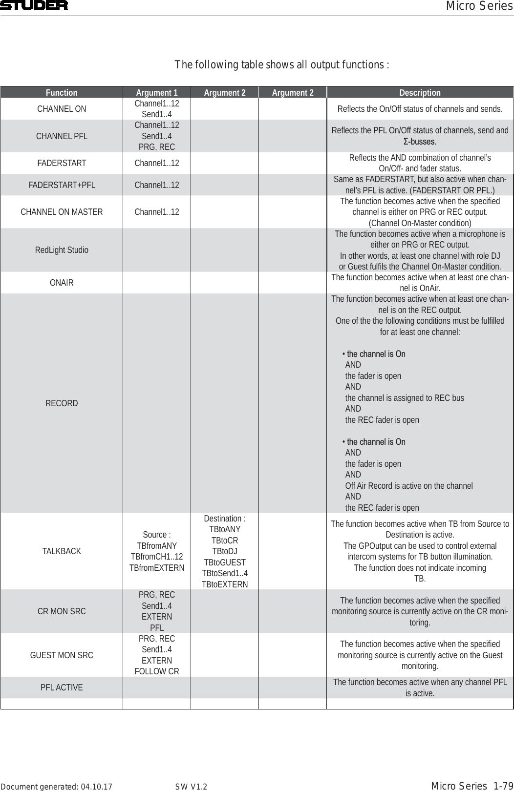
![Micro SeriesMicro Series 1-77Document generated: 04.10.17 SW V1.2[5] Function Defines the function that is triggered from the GPI[6] Parameters Depending on the GPI Function, a parameter of the function can be chosen here. (E.g. a channel number).The two following tables show all Input Functions :Momentary only or momentary and latching functions :Function Argument 1 Argument 2 Argument 2 DescriptionCHANNEL ON Channel 1..12Send 1..4 -- - Activate/Deactivate the specified On/OffCHANNEL PFL Channel 1..12Send 1..4PRG, REC - - Activate/Deactivate the specified PFL On/OffCOUGH Channel 1..12 - - Activate/Deactivate TB Mic Cut of the specified Chan-nelTALKBACKSource :TBfromCh1..12TBfromExternDestination :TBtoCRTBtoDJTBtoGuestTBtoSend1..4TBtoExtern-Activate/Deactivate TB from specified source todes-tinationLSP CUT - - - Activate/Deactivate the loudspeaker CutLSP DIM - - - Activate/Deactivate the loudspeaker DimEvent driven functions:Function Argument 1 Argument 2 Argument 2 DescriptionSET CR MON SRC PRG, RECSend1..4EXTERN Set the specified source for the CR monitoringSET GUEST MON SRCPRG, RECSend1..4EXTERNFOLLOW CRSet the specified source for the Guest monitoringLOAD SNAPSHOT Snapshot name Recall the specified snapshotTRACK PLAYER NEXTSTOP Start the next track in the PlaylistStop the PlaylistRESET PFL Reset any active channel PFL. (Similar to the Reset PFL button on the GUI).](https://usermanual.wiki/Harman/MICROCORE/User-Guide-3749418-Page-94.png)
![Micro Series1-78 Micro Series Document generated: 04.10.17SW V1.2The GPO tap is the page where all general purpose output functions are con-figured and activated.1 2[1] On/Off Lets the operator activate the GPIO. The button is illuminated when active.[2] Dir The Polarity of the signal at the input pin: High=Active is positive-, Low=Active is negative polarity.[3] Time Depending on the Time, the Output Logic either operates as level- or edge sensitive.[4] Sensitivity The Sensitivity defines how the value affects the signal at the output pin. Possible values are RISING EDGE, FALLING EDGE or LEVEL.[5] Function Chooses the function that triggers the GPO signal.[6] Parameters Parameters defines the channel number on which the function is based on.](https://usermanual.wiki/Harman/MICROCORE/User-Guide-3749418-Page-95.png)
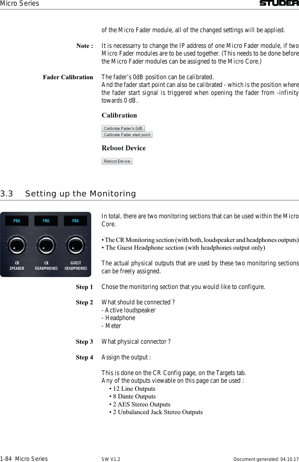
![Micro Series1-80 Micro Series Document generated: 04.10.17SW V1.2The Desk Modules tap is the page where one or two Micro Fader modules can be configured to be used with the Micro Core.1212 1 1 1 1 11[1] MulticastGroup The multicast group address setting used for the communication to the Micro Fader modules can be entered here.[2] Cloud ID Current Cloud ID of the Core[3] Node Name Shows the Micro Core’s Node_Name[4] Port Displays settings of the Cloud communication[5] Multicast TTL Hop Limit Displays settings of the Cloud communication[6] Name Shows the Node_Name as configured in the Setup of the Micro Fader module[7] Cloud ID Current Cloud ID of the Micro Fader module[8] Node ID Node ID of the Micro Fader module[9] Pairing The column shows the pairing state of a Micro Fader module](https://usermanual.wiki/Harman/MICROCORE/User-Guide-3749418-Page-97.png)
![Micro SeriesMicro Series 1-81Document generated: 04.10.17 SW V1.2[10] State Shows the current Connection/Pairing state of Micro Fader modules within the network. Icon DescriptionPaired to this Core - ConnectedPaired to this Core - disconnectedPaired to this Core - connected, but different Cloud IDNot paired[11] Version The column indicates the Micro Fader module firmware version for each Micro Fader module available on the network.[12] Disconnect All This button disconnects all paired Micro Fader modules, which are currently available on the network.[13] Channel Selection ComboBox It is used to pair or un-pair a Micro Fader module.[14] Locate the LOCATE function is activated on the corresponding Micro Fader module - the Micro Fader module will flash for five seconds.[15] Update FW It allows updating the firmware on each Micro Fader module which is paired to the Micro Core.](https://usermanual.wiki/Harman/MICROCORE/User-Guide-3749418-Page-98.png)
![Micro Series1-82 Micro Series Document generated: 04.10.17SW V1.2The System tab on the settings page displays current FW and HW versions and lets the operater reset the console to factory settings.12[1] Revision Status Displays current Firmware, Hardware and Gateware version numbers.[2] Factory Reset Resets the mixer to factory settings.](https://usermanual.wiki/Harman/MICROCORE/User-Guide-3749418-Page-99.png)