Harman MICROCORE Mixing Console User Manual onair
Harman International Industries, Inc Mixing Console onair
Harman >
User Manual
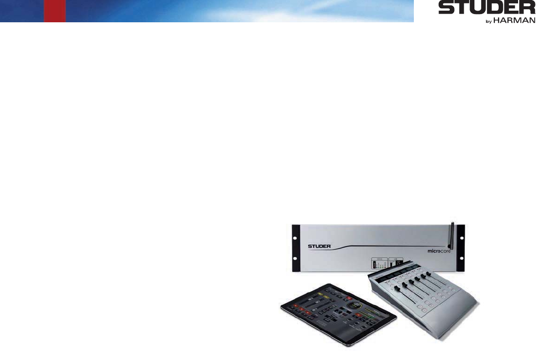
Studer Micro Series
SW Version 1.2
Operating Instructions

Disclaimer
The information in this document has been carefully checked and is believed to be accurate at the time of publica-
tion. However, no responsibility is taken by us for inaccuracies, errors, or omissions, nor is any liability assumed for
any loss or damage resulting either directly or indirectly from use of the information contained within it.
Prepared and edited by Copyright by Studer Professional Audio GmbH
Studer Professional Audio GmbH
Technical Documentation
Riedthofstrasse 214
CH-8105 Regensdorf - Switzerland
http://www.studer.ch Subject to change
Studer is a registered trade mark of Studer Professional Audio GmbH, Regensdorf
Order no. XXXXXXX

I
For Your Own Safety and to Avoid Invalidation of the Warranty
Please Read This Section Carefully
-
-
Safety Information
II
!
!
Although your new console will not make any noise until you feed it signals,
it has the capability to produce sounds that, when monitored through a moni-
tor system or headphones, can damage hearing over time.The table below is
taken from the Occupational Safety & Health Administration directive on
occupational noise exposure (1926.52):
Duration per day [h] Sound level [dBA, slow response]
890
692
495
397
2 100
1.5 102
1 105
0.5 110
<0.25 115
Conforming to this directive will minimise the risk of hearing damage caused
by long listening periods. A simple rule to follow is: The longer you listen, the
lower the average volume should be. Please take care when working with your
audio system – if you are manipulating controls which you don’t understand
(which we all do when we are learning), make sure your monitoring level is
turned down. Remember that your ears are the most important tool of your
trade. Look after them, and they will look after you. Most importantly: Don’t
be afraid to experiment to find out how each parameter affects the sound;
this will extend your creativity and help you to get the best results.
!
Safety Information
III
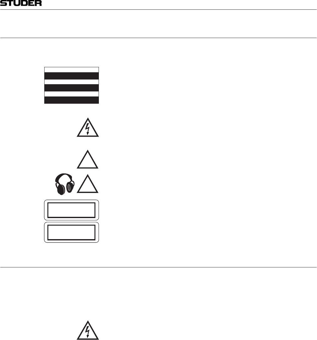
A1 Safety Symbol Guide
For your own safety and to avoid invalidation of the warranty, all text marked
with these symbols should be read carefully.
To reduce the risk of electric shock, do not remove covers. No user-serviceable
parts inside. Refer servicing to qualified service personnel (i.e., persons
having appropriate technical training and experience necessary to be aware
of hazards to which they are exposed in performing a repair action, and of
measures to minimize the danger of themselves).
The lightning flash with arrowhead symbol is intended to alert the user to the
presence of un-insulated “dangerous voltage” within the product’s enclosure
that may be of sufficient magnitude to constitute a risk of electric shock to
persons.
The exclamation point within an equilateral triangle is intended to alert the
user to the presence of important operating and maintenance (servicing)
instructions in the literature accompanying the appliance.
Headphones safety warnings contain important information and useful tips
on headphone outputs and monitoring levels.
Assemblies or sub-assemblies of this product can contain opto-electronic
devices. As long as these devices comply with Class I of laser or LED prod-
ucts according to EN 60825-1:1994, they will not be expressly marked on
the product. If a special design should be covered by a higher class of this
standard, the device concerned will be marked directly on the assembly or
sub-assembly in accordance with the above standard.
A2 First Aid
Separate the person as quickly as possible from the electric power source:
material (such as wood or plastic)
Warning! Do not touch the person or his clothing before the power is turned off,
otherwise you stand the risk of suffering an electric shock as well!
CAUTION
RISK OF ELECTRIC SHOCK
DO NOT OPEN
ACHTUNG
GEFAHR: ELEKTRISCHER SCHLAG
NICHT ÖFFNEN
ATTENTION
RISQUE DE CHOC ELECTRIQUE
NE PAS OUVRIR
!
CLASS 1
LASER PRODUCT
CLASS 1
LED PRODUCT
!
Safety Information

IV
B General Installation Instructions
Please consider besides these general instructions also any product-specific
instructions in the “Installation” chapter of this manual.
B1 Unpacking
Check the equipment for any transport damage. If the unit is mechanically
damaged, if liquids have been spilled or if objects have fallen into the unit,
it must not be connected to the AC power outlet, or it must be immediately
disconnected by unplugging the power cable. Repair must only be performed
by trained personnel in accordance with the applicable regulations.
B2 Installation Site
Install the unit in a place where the following conditions are met:
within the specified limits during operation of the unit. Relevant values
are the ones at the air inlets of the unit (refer to Appendix 1)
precautions must be taken before and after operation (refer to Appendix
1)
unit are a functional part of the design and must not be blocked in any
way during operation (e.g. by objects placed upon them, placement of the
unit on a soft surface, or installation of the unit within a rack or piece of
furniture)
-
light, spotlights)
B3 Earthing and Power Supply
Earthing of units with mains supply (class I equipment) is performed via
battery operation (< 60 V, class III equipment) must be earthed separately.
Earthing the unit is one of the measures for protection against electrical shock
hazard (dangerous body currents). Hazardous voltage may not only be caused
by a defective power supply insulation, but may also be introduced by the
connected audio or control cables.
If the unit is installed with one or several external connections, its earthing
must be provided during operation as well as while the unit is not operated.
If the earthing connection can be interrupted, for example, by unplugging
the mains plug of an external power supply unit, an additional, permanent
earthing connection must be installed using the provided earth terminal.
Avoid ground loops (hum loops) by keeping the loop surface as small as
possible (by consequently guiding the earth conductors in a narrow, parallel
way), and reduce the noise current flowing through the loop by inserting an
additional impedance (common-mode choke).
Installation
V
Installation / EMC
Should the equipment be delivered without a matching mains cable, the
latter has to be prepared by a trained person using the attached female plug
(IEC 320 / C13 or IEC 320 / C19) with respect to the applicable regulations
in your country.
line voltage matches the equipment rating (voltage, frequency) within the
admissible tolerance. The equipment fuses must be rated in accordance with
the specifications on the equipment.
Equipment supplied with a 3-pole appliance inlet (protection conforming to
class I equipment) must be connected to a 3-pole AC power outlet in such a
way that the equipment cabinet is connected to the protective earth.
For information on mains cable strain relief, please refer to Appendix 2.
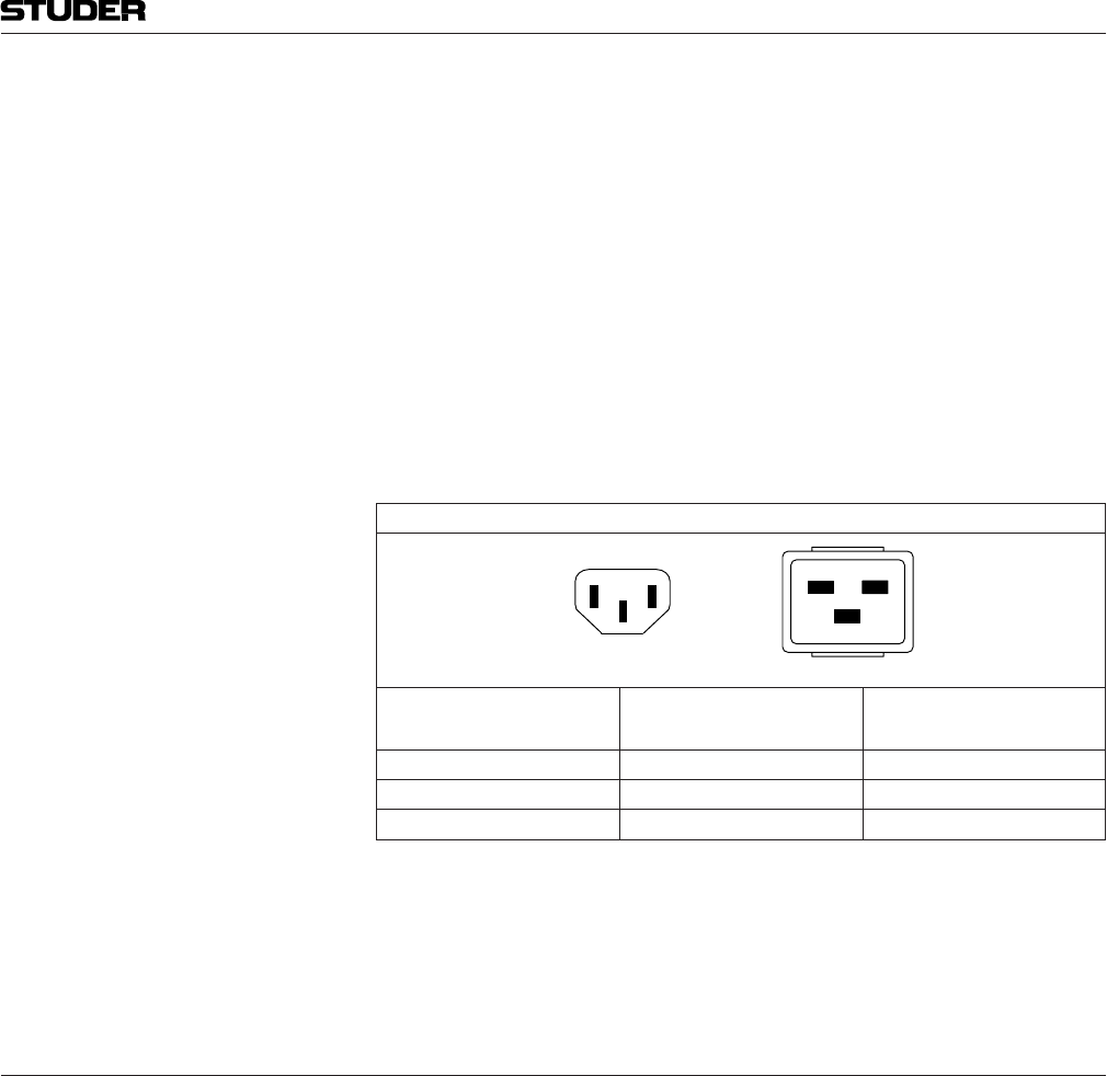
Female Plugs (IEC320), Front-Side View:
European Standard
(CENELEC) North American Standard
(NAS)
Brown L (Live) Black
Blue N (Neutral) White
Green/Yellow PE (Protective Earth) Green (or Green/Yellow)
Equipment of this protection class must be earthed using the provided earth
terminal if one or more external signals are connected to the unit (see expla-
nation at the beginning of this paragraph).
B4 Electromagnetic Compatibility (EMC)
The unit conforms to the protection requirements relevant to electromagnetic
a way that other equipment and systems can be operated normally
that it can operate properly
The unit has been tested and conforms to the EMC standards of the speci-
fied electromagnetic environment, as listed in the following declaration.
The limits of these standards ensure protection of the environment and cor-
responding noise immunity of the equipment with appropriate probability.
However, a professional installation and integration within the system are
imperative prerequisites for operation without EMC problems.
For this purpose, the following measures must be followed:
the supplied accessories
components (systems, equipment) that also fulfill the EMC standards for
the given environment
PE
LN
IEC 320 / C19IEC 320 / C13
PE
LN

VI
(class I equipment must be connected with a protective ground conduc-
tor) and that also takes into consideration the EMC requirements. When
deciding between radial, surface, or combined grounding, the advantages
and disadvantages should be carefully evaluated in each case
shield to the corresponding connector terminal or housing should have a
large surface and be corrosion-proof. Please note that a cable shield con-
nected only single-ended can act as a transmitting or receiving antenna
within the corresponding frequency range
surface as small as possible, and reduce the noise current flowing through
the loop by inserting an additional impedance (e.g. common-mode choke).
-
ate floor covering (e.g. a carpet with permanent electrostatic filaments) and
by keeping the relative humidity above 30%. Further measures (e.g. con-
ducting floor) are usually unnecessary and only effective if used together
with corresponding personal equipment
care that the surrounding building structure allows for sufficient capacitive
coupling of the operator. This coupling can be improved by an additional,
conducting surface in the operator’s area, connected to the equipment
housing (e.g. metal foil underneath the floor covering, carpet with conduc-
tive backing)
C Maintenance
All air vents and openings for operating elements (faders, rotary knobs) must
be checked on a regular basis, and cleaned in case of dust accumulation. For
cleaning, a soft paint-brush or a vacuum cleaner is recommended.
Cleaning the surfaces of the unit is performed with a soft, dry cloth or a soft
brush.
Persistent contamination can be treated with a cloth that is slightly humidified
with a mild cleaning solution, such as dishwashing detergent.
For cleaning display windows, commercially available computer/TV screen
Never use any solvents for cleaning the exterior of the unit! Liquids must
never be sprayed or poured on directly!
For equipment-specific maintenance information please refer to the corre-
sponding chapter in the operating and service manuals.
D Electrostatic Discharge during Maintenance and Repair
Many semiconductor components are sensitive to electrostatic discharge
(ESD). The lifespan of assemblies containing such components can be dras-
tically reduced by improper handling during maintenance and repair. Please
observe the following rules when handling ESD sensitive components:
packing material specifically provided for this purpose
EMC / Maintenance / ESD

VII
ESD / Repair
assembly must be sent back to the supplier in the same packing material
in which the replacement assembly was shipped. If this should not be the
case, any claim for a possible refund will be null and void
protected areas (EPA, e.g. area for field service, repair or service bench)
and only be touched by persons wearing a wristlet connected to the
ground potential of the repair or service bench by a series resistor. The
equipment to be repaired or serviced as well as all tools and electrically
semi-conducting work, storage, and floor mats should also be connected
to this ground potential
contact with electrostatically chargeable or metallic surfaces (voltage
puncture, discharge shock hazard)
damage due to inadmissible voltages or compensation currents, electrical
connections should only be established or separated when the equipment
is switched off and after any capacitor charges have decayed
E Repair
this reason the following precautions must be observed:
with the applicable regulations
outlet before any housing parts are removed
hazardous charges (e.g. capacitors, picture tubes) must not be touched until
they have been properly discharged. Do not touch hot components (power
semiconductors, heat sinks, etc.) before they have cooled off
on, no un-insulated circuit components and metallic semiconductor hous-
ings must be touched, neither with bare hands nor with un-insulated tools
Certain components pose additional hazards:
semiconductors (Observe the component’s polarity. Do not short battery
terminals. Replace batteries only by the same type)
electrolyte
Such components should only be handled by trained personnel who are prop-
erly protected (e.g. protection glasses, gloves)
VIII
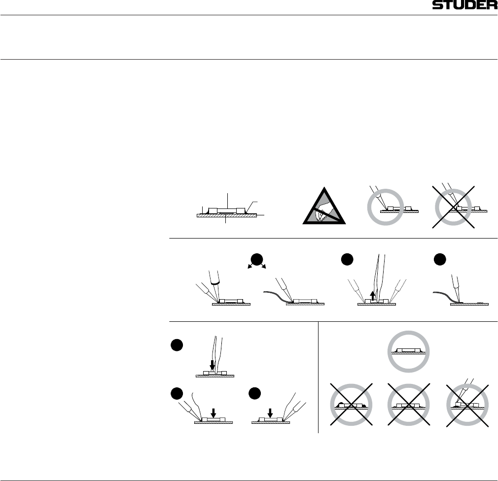
E1 SMD Components
Studer has no commercially available SMD components in stock for service
purposes. For repair, the corresponding devices have to be purchased locally.
The specifications of special components can be found in the service manual.
SMD components should only be replaced by skilled specialists using appro-
priate tools. No warranty claims will be accepted for circuit boards that have
been damaged. Proper and improper SMD soldering joints are illustrated
below.
Dismounting
Mounting Examples
Solder
SMD
Component
Copper
Track
Adhesive
Soldering Iron
Desoldering
Iron
Desolder
Wick
Heat and Remove Cleaning
Solder
Ø 0.5...0.8 mm
Heatin
g
Time < 3 s
p
er Side
Soldering
Iron Desolder
Wick
PCB
3
2
1
3
2
1
F Disposal
The packing materials have been selected with environmental and disposal
issues in mind. All packing material can be recycled. Recycling packing saves
raw materials and reduces the volume of waste.
If you need to dispose of the transport packing materials, please try to use
recyclable means.
must be disposed of professionally. Please return your used equipment via an
authorized specialist dealer or via the public waste disposal system, ensuring
any material that can be recycled is.
Please take care that your used equipment cannot be abused. To avoid abuse,
delete sensitive data from any data storage media. After having disconnected
your used equipment from the mains supply, make sure that the mains con-
nector and the mains cable are made useless.
Repair / Disposal

IX
G Declarations of Conformity
G1 Class B Equipment - FCC Notice
Warning! Changes or modifications to this unit not expressly approved by the party
responsible for compliance could void the user’s authority to operate the
equipment.
Note: This equipment has been tested and found to comply with the limits for a
ClassBdigitaldevice,pursuanttoPart15oftheFCCRules.Theselimits
are designed to provide reasonable protection against harmful interference
in a residential installation. This equipment generates, uses and can radiate
radio frequency energy and, if not installed and used in accordance with the
instructions, may cause harmful interference to radio communications.
However, there is no guarantee that interference will not occur in a particular
installation. If this equipment does cause harmful interference to radio or
television reception, which can be determined by turning the equipment off
and on, the user is encouraged to try to correct the interference by one or more
of the following measures:
• Reorientorrelocatethereceivingantenna.
• Increasetheseparationbetweentheequipmentandreceiver.
• Connecttheequipmentintoanoutletonacircuitdifferentfromthatto
which the receiver is connected.
• Consultthedealeroranexperiencedradio/TVtechnicianforhelp.
This device complies with Part 15 of the FCC Rules. Operation is subject to
the following two conditions: (1) this device may not cause harmful interfer-
ence, and (2) this device must accept any interference received, including
interference that may cause undesired operation.
G2 Industry Canada – IC Notice
This device complies with Industry Canada licence-exempt RSS standard(s).
Operation is subject to the following two conditions: (1) this device may not
cause interference, and (2) this device must accept any interference, including
intereference that may cause undesired operation of the device.
Le présent appareil est conforme aux CNR d’Industrie Canada applicables
aux appareils radio exempts de licence. L’exploitation est autorisée aux deux
conditions suivantes: (1) l’appareil ne doit pas produire de brouillage, et (2)
l’utilisateur d’appareil doit accepter tout brouillage radioélectrique subi,
même si le brouillage est susceptible d’en compromettre le fonctionnement.
Conformity
The device for operation in the band 5150–5250 MHz is only for indoor use to reduce the potential for harmful
interference to co-channel mobile satellite systems.
The device and the antenna should be installed and operated with a minimum distance of 20 cm from all persons.

X
G3 CE Declaration of Conformity
We,
declare under our sole responsibility that the product
directives and amendments
is in conformity with the following standards or normative documents:
EN 60065:2014
EN 301 489-1 v2.0.0
EN 301 489-17 v3.2.0
EN 300 440 v2.1.1
EN 300 328 v2.1.1
EN 301 893 v2.1.1
M.Lienert, Manager R&D
Appendix

XI
Appendix 1: Air Temperature and Humidity
General
Normal operation of the unit or system is warranted under the ambient condi-
tions defined by EN 60721-3-3, set IE32, value 3K3.
This standard consists of an extensive catalogue of parameters, the most
important of which are: ambient temperature +5...+40 °C, relative humidity
5...85% (i.e., no formation of condensation or ice); absolute humidity 1...25 g/
m³; rate of temperature change < 0.5 °C/min. These parameters are dealt with
in the following paragraphs.
-
Ambient Temperature
-
ture range (i.e. temperature of the incoming air) of +5 °C to +40 °C. When
rack mounting the units, the intended air flow and herewith adequate cooling
must be provided. The following facts must be considered:
-
ductor components is 0 °C to +70 °C (commercial temperature range for
operation)
always cooler than 70 °C
air flow of 2.65 m³/min is required
A rack dissipating P = 800 W requires an air flow of 0.8 * 2.65 m³/min which
corresponds to 2.12 m³/min.
failure or illumination with spot lamps), the outgoing air temperature must
be measured directly above the modules at several places within the rack.
The trigger temperature of the sensors should be 65 °C to 70 °C
Frost and Dew
The unsealed system parts (connector areas and semiconductor pins) allow
for a minute formation of ice or frost. However, formation of dew visible to
the naked eye will already lead to malfunctions. In practice, reliable opera-
tion can be expected in a temperature range above –15 °C, if the following
general rule is considered for putting the cold system into operation:
If the air within the system is cooled down, the relative humidity rises. If it
reaches 100%, condensation will arise, usually in the boundary layer between
the air and a cooler surface, together with formation of ice or dew at sensi-
tive areas of the system (contacts, IC pins, etc.). Once internal condensation
occurs, trouble-free operation cannot be guaranteed, independent of tempera-
ture.
-
mation of condensation or ice. Only with a minute formation of ice, direct
Appendix
XII
evaporation (sublimation) may be expected; otherwise the system must be
heated and dried while switched off.
A system without visible internal formation of ice or condensation should be
heated up with its own heat dissipation, as homogeneously (and subsequently
as slow) as possible; the ambient temperature should then always be lower
than the one of the outgoing air.
If it is absolutely necessary to operate the cold system immediately within
warm ambient air, this air must be dehydrated. In such a case, the absolute
humidity must be so low that the relative humidity, related to the coldest
system surface, always remains below 100%.
Ensure that the enclosed air is as dry as possible when powering off (i.e. before
switching off in winter, aerate the room with cold, dry air, and remove humid
objects such as clothes from the room).
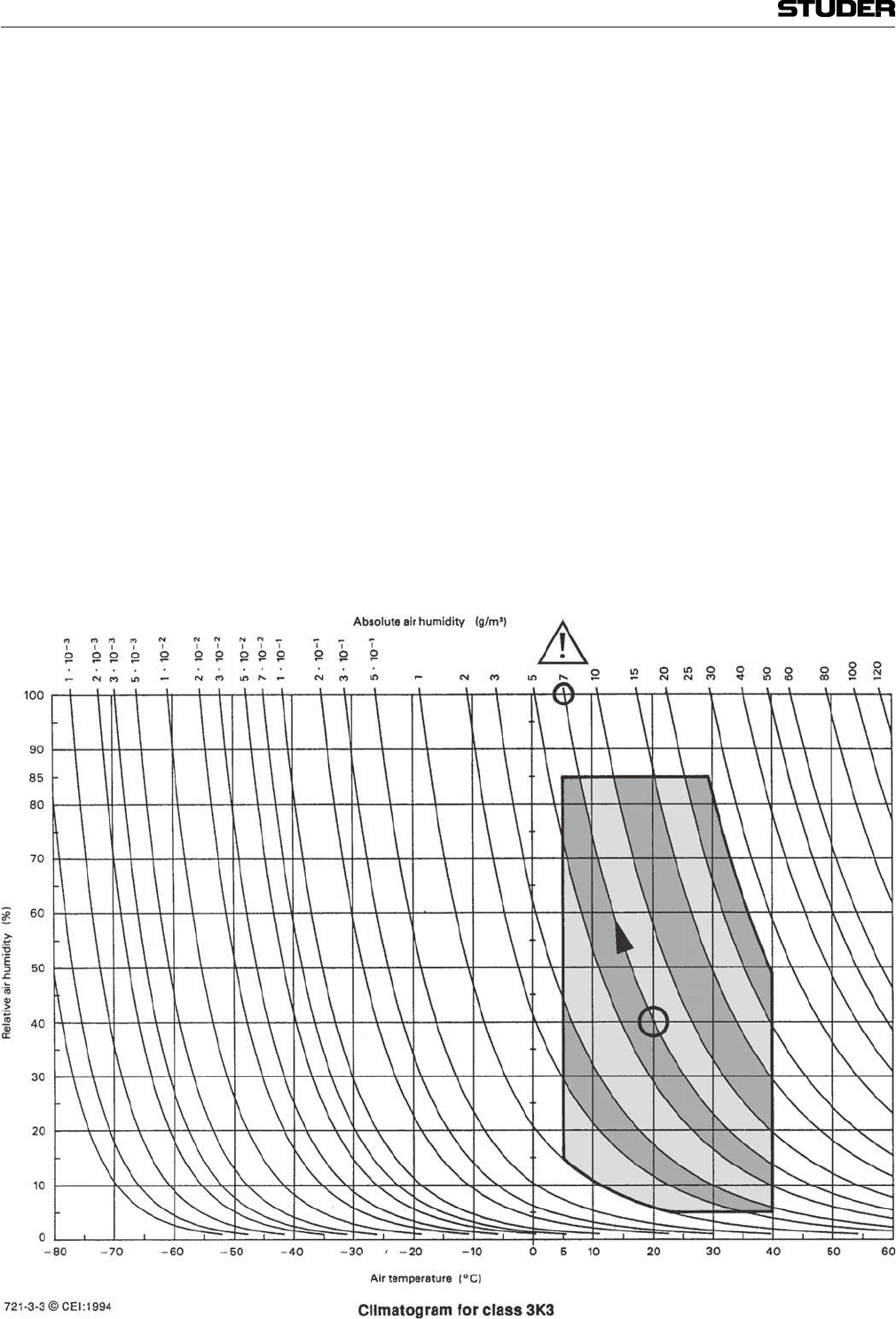
These relationships are visible from the following climatogram. For a con-
trolled procedure, thermometer and hygrometer as well as a thermometer
within the system will be required.
+20 °C and a relative humidity
of 40% is switched off in the evening. If the temperature falls below +5 °C,
the relative humidity will rise to 100% (7 g/m³); dew or ice will be forming.
+20 °C and a relative
humidity of 40%. On all parts being cooler than +5 °C, dew or ice will be
forming.
Appendix
XIII
Appendix
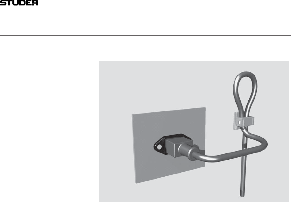
Appendix 2: Mains Connector Strain Relief
For anchoring connectors without a mechanical lock (e.g. IEC mains connec-
tors), we recommend the following arrangement:
The cable clamp shipped with your unit is auto-adhesive. For mounting please
follow the rules below:
or other contaminants. Recommended application temperature range is
+20 °C to +40 °C
apply it firmly to the surface at the desired position. Allow as much time as
possible for curing. The bond continues to develop for as long as 24 hours
purpose, a self-tapping screw and an M4 bolt and nut are included
press down the internal top cover until the cable is fixed

XIV
Appendix 3: Software License
Use of the software is subject to the Studer Professional Audio Software
License Agreement set forth below. Using the software indicates your accep-
tance of this license agreement. If you do not accept these license terms, you
are not authorized to use this software.
-
ditions, Studer Professional Audio GmbH (hereinafter ‘Studer’) grants the
right to use programs developed by Studer as well as those of third parties
which have been installed by Studer on or within its products. References
to the license programs shall be references to the newest release of a license
program installed at the Customer’s site.
Programs Covered by the Agreement
The following Terms and Conditions grant the right to use all programs of
Studer that are part of the System and/or its options at the time of its delivery
to the Customer, as well as the installation software on the original data disk
and the accompanying documentation (‘License Material’). In this Agreement
the word ‘Programs’ shall have the meaning of programs and data written in
machine code.
do not accept these license terms, you are not authorized to use this software.
Programs of third parties are all programs which constitute part of the System
and/or its options at the time of delivery to the Customer but have not been
developed by Studer. The following conditions are applicable to programs of
third parties:
-
ment attached hereto (if applicable), which is an integral part of this
Agreement. The Customer shall sign any and all License Agreements for
all further programs of third parties installed on the system. The Customer
shall be deemed to have received all License Agreements upon delivery
of the system and/or its options
-
ties (express or implied) as to the programs of third parties. The Customer
waives any and all claims versus Studer for any consequential damages,
which might occur due to defects of these programs
Right of Use
Studer grants the Customer the non-exclusive right to use the License Ma-
terial in one copy on the system and/or its options as laid down by the Sales
Agreement concluded between the parties and all Terms and Conditions
which shall be deemed to form and be read and construed as part of the Sales
Agreement. This right is assignable according to the ‘Assignability’ paragraph
hereinafter.
The Customer is not entitled to alter or develop further the License Material
except within the expressly permitted configuration possibilities given by the
software installed on the system or elsewhere. All altered programs, includ-
ing but not limited to the products altered within the permitted configuration
possibilities, are covered by this License Agreement.
Appendix

XV
Reverse engineering is only permitted with the express consent of Studer.
The consent of Studer can be obtained but is not limited to the case in which
the interface software can not be provided by Studer. In any case Studer has
to be informed immediately upon complete or partial reverse engineering.
The Customer is entitled to make one copy of all or parts of the License
Material as is necessary for the use according to this Agreement, namely for
backup purposes. The Customer shall apply the copyright of Studer found on
the License Material onto all copies made by him. Records shall be kept by
the Customer regarding the amount of copies made and their place of keeping.
The responsibility for the original program and all copies made lies with the
Customer. Studer is entitled to check these records on first request. Copies
not needed anymore have to be destroyed immediately.
The License Material is a business secret of Studer. The Customer shall not
hand out or in any way give access to parts of or the complete License Material
to third parties nor to publish any part of the License Material without prior
written consent of Studer. The Customer shall protect the License Material
and any copies made according to the paragraph above by appropriate defense
measures against unauthorized access. This obligation of non-disclosure is a
perpetual obligation.
Third parties are entitled to have access to the License Material if they use the
License Material at the Customer’s site in compliance with this Agreement.
-
lation software on the original data media. The Customer shall safeguard the
original data media accordingly.
The rights granted to the Customer according to this License Agreement shall
only be assignable to a third party together with the transfer of the system
and/or its options and after the prior written consent of Studer.
Rights to License Material
With the exception of the right of use granted by this License Agreement all
proprietary rights to the License Material, especially the ownership and the
intellectual property rights (such as but not limited to patents and copyright)
remain with Studer even if alterations, customized changes or amendments
have been made to the License Material.
Studer’s proprietary rights are acknowledged by the Customer. The Customer
shall undertake no infringements and make no claims of any patent, registered
design, copyright, trade mark or trade name, or other intellectual property
right.
Warranty, Disclaimer, and Liability
For all issues not covered herewithin, refer to the ‘General Terms and Condi-
tions of Sales and Delivery’ being part of the sales contract.

Micro Series
Micro Series 1-1
Document generated: 04.10.17 SW V1.2
MICRO SERIES
1 System Description ...........................................................................................................................................3
1.1 Introduction ........................................................................................................................................................3
1.2 Hardware ............................................................................................................................................................3
1.2.1 Micro Core............................................................................................................................................................3
1.2.1.1 Front side connectors.................................................................................................................................................4
1.2.1.2 Front side status LEDs...............................................................................................................................................4
1.2.1.3 Rear side connectors..................................................................................................................................................5
1.2.1.4 Mains Power ..............................................................................................................................................................5
1.2.2 Micro Fader...........................................................................................................................................................6
1.2.2.1 Operating Elements....................................................................................................................................................6
1.2.2.2 Connectors .................................................................................................................................................................7
1.2.2.3 iPad mount.................................................................................................................................................................7
1.3 Main Features.....................................................................................................................................................8
1.4 How can it be operated.......................................................................................................................................8
1.4.1 GUI........................................................................................................................................................................8
1.4.2 Micro Fader...........................................................................................................................................................8
1.5 Hookup possibilities via Network......................................................................................................................9
1.6 Hookup possibilites direct GUI Control...........................................................................................................10
1.7 Applications......................................................................................................................................................11
1.7.1 Hookup Diagram Application 1 - Radio OnAir Production................................................................................11
1.7.2 Hookup Diagram Application 2 - TV OnAir Production....................................................................................12
1.7.3 Hookup Diagram Application 3 - Post Production .............................................................................................13
2 GUI Operation ................................................................................................................................................14
2.1 L1 - The operation level (for DJs)....................................................................................................................14
2.1.1 Main Page............................................................................................................................................................14
2.1.2 Mixer Channels...................................................................................................................................................16
2.1.2.1 Channel Roles..........................................................................................................................................................16
2.1.3 Chan View...........................................................................................................................................................17
2.1.4 Send View ...........................................................................................................................................................20
2.1.5 Sum View............................................................................................................................................................21
2.1.6 Play(er) View ......................................................................................................................................................22
2.1.6.1 Track Player Operation.........................................................................................................................................23
2.1.6.2 Jingle Player Operation............................................................................................................................................25
2.1.7 Meter View..........................................................................................................................................................27
2.1.8 Central Section....................................................................................................................................................28
2.1.9 Right Section.......................................................................................................................................................29
2.1.9.1 USB Recorder..........................................................................................................................................................30
2.1.9.2 User Snapshots.........................................................................................................................................................32
2.1.9.3 TB External..............................................................................................................................................................34
2.2 L2 - The options level.......................................................................................................................................35
2.2.1 Channel options...................................................................................................................................................35
2.2.2 Bus options..........................................................................................................................................................38
2.2.3 Meter options .....................................................................................................................................................40
2.2.4 Snapshot options.................................................................................................................................................40

Micro Series
1-2 Micro Series Document generated: 04.10.17
SW V1.2
2.2.5 CR Monitoring options .......................................................................................................................................41
2.2.6 Guest Monitoring options ...................................................................................................................................42
2.3 L3 - The configuration level.............................................................................................................................43
2.3.1 Channel config....................................................................................................................................................43
2.3.2 Bus Config ..........................................................................................................................................................54
2.3.3 CR Monitoring Config........................................................................................................................................59
2.4 Settings view.....................................................................................................................................................63
3 Setup.................................................................................................................................................................83
3.1 Setting up the Network.....................................................................................................................................83
3.2 Setting up the Micro Fader modules.................................................................................................................83
3.3 Setting up the Monitoring.................................................................................................................................84
3.4 Setting up TB....................................................................................................................................................86
3.5 Setting up N-1 / Sends......................................................................................................................................87
3.6 Setting up GPIOs..............................................................................................................................................87
3.7 Setting up Dante...............................................................................................................................................89
3.8 Firmware update...............................................................................................................................................89
3.9 Emergency factory reset...................................................................................................................................90
4 Blockdiagram ..................................................................................................................................................91
5 Technical Specifications .................................................................................................................................92
6 Glossary ...........................................................................................................................................................93
Micro Series
Micro Series 1-3
Document generated: 04.10.17 SW V1.2
1 SYSTEM DESCRIPTION
1.1 Introduction
The Studer Micro Series is a compact OnAir broadcast and production mixing
system.
It has been designed with focus on very easy operatability - whilst providing
features for professional broadcast production, which are normally only found
in more complex OnAir mixers.
Eventough it has specific OnAir features, it can also be used as a versatile
production mixer for many other applications.
The Studer Micro Series can currently be used as a standalone unit, and later
it will have the functionality to be part of a networked studio environment.
The minimal system consists of a base unit only which is called Micro Core.
The Micro Core is then operated via a browser GUI, which can be run on a
tablet, notebook or desktop computer. (iOS, Android, Windows, MacOS, and
Linux platforms are supported).
For local operation, a computer screen and mouse and keyboard can be
directly connected to the Micro Core to operate the GUI.
For users who wish dedicated hardware controls, the Micro Core can be
combined with one or two desk modules - adding faders, buttons and channel
displays for real hands-on control. The desk module is called Micro Fader.
This manual is written for users that operate the mixer - and also for setup
and installation of the mixer (last part in the manual).
1.2 Hardware
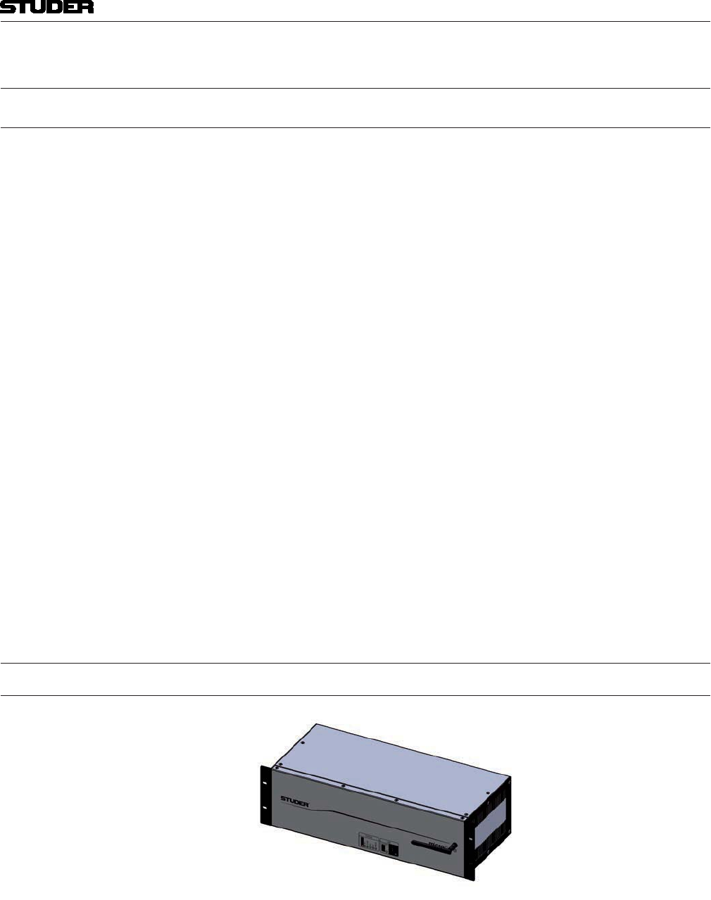
1.2.1 Micro Core
The heart of the Micro Series is the fanless, rackmountable 3 RU Micro Core.
It is the actual mixing engine, also providing USB connectivity and status
LEDs on the front side, and audio I/O as well as a multitude of other connec-
tors on the rear side.
By using the included rackmount-kit, the Micro Core can also be mounted in
“reversed” way , making it easier to access all audio I/Os from the front of
the rack.
Micro Series
1-4 Micro Series Document generated: 04.10.17
SW V1.2
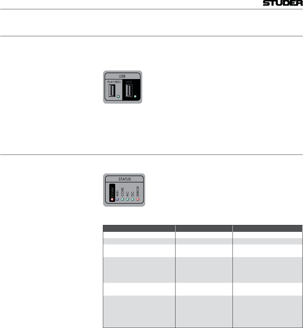
1.2.1.1 Front side connectors
USB for logging (not enabled in SW V1.0)
USB for playback and recording
WLAN antenna (not enabled in SW V1.0)
The LED next to the playback and recording USB port becomes green after
the inserted media has been performance-tested and is ready for operation.
1.2.1.2 Front side status LEDs
The Core Status indication LEDs are described in the table below.
Status Colour Description
Power AC Green AC Power OK
Power DC Green DC Power OK
Core Ready Green Core started up and ready for
operation
Error Red
The system detected an error or
warning.
Refer to the Error Status page
for more details.
Wi-Fi Blue Illuminated as long as Wi-Fi is
active
OnAir Red
Illuminated if the Micro Core is
onair.
For details refer to chapter 2.1.8
OnAir
Red Light Indication.
Micro Series
Micro Series 1-5
Document generated: 04.10.17 SW V1.2
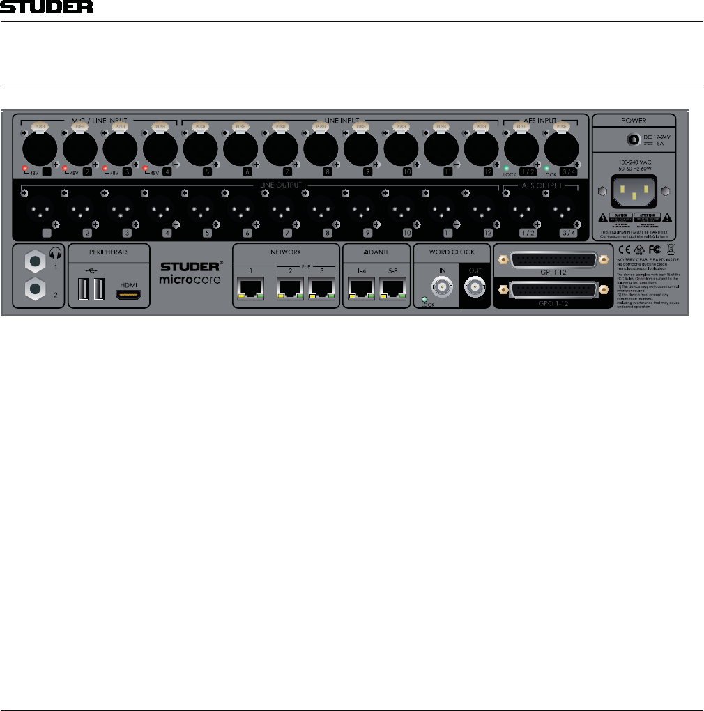
1.2.1.3 Rear side connectors
Discrete audio inputs 4 x balanced HQ Mic/Line inputs on XLR
8 x balanced Line inputs on XLR
2 x AES3 with SFC on XLR
Discrete audio outputs 12 x balanced line out XLR
2 x AES3 on XLR
2 x stereo headphones
Networked audio I/O 2 x AES67/Dante (4 audio channels each)
Other connectors Mains power
DC Power
Word Clock In and Out
GPIO
Ethernet
HDMI and 2x USB for GUI
2x RJ45 including PoE for Micro Fader modules
1.2.1.4 Mains Power
The Micro Core is primarily powered by an integrated wide-range AC power
supply with IEC type standard connector.
For mobile use (automotive battery) or power redundancy an additional DC
power input with lockable connector can also be found just above the AC
connector.
Micro Series
1-6 Micro Series Document generated: 04.10.17
SW V1.2
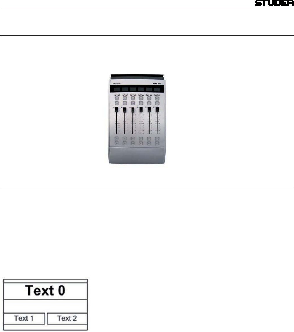
1.2.2 Micro Fader
Up to two Micro Fader modules can be connected to one Micro Core - giving
access to up to 12 faders. This allows professional Radio OnAir operation.
Connection is via a single cat5 cable for communication protocol and power.
1.2.2.1 Operating Elements
There are six non-motorized faders. Each channel strip has its own display
Per channel strip, two small option buttons are placed directly below the
display. Further down, two large buttons are placed above the fader. These
buttons are used for Rec an Cue functions. Then below the fader there are
another two large buttons : the On- and the PFL /Off button.
Also a signal indication- as well as an overload LED are placed between the
fader and the upper two large buttons.
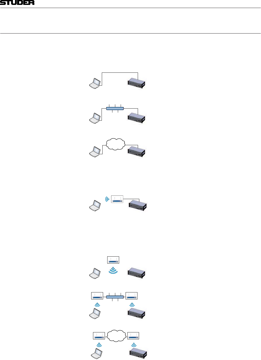
Display The Micro Fader module provides a two row LCD display to indicate :
( The background of the function name is inverted when the function is active.)
(default) to blue. The backlight is flashing if a channel that is On-Master is
pending on snapshot parameter recall.
Buttons The Micro Fader module features six buttons per channel strip. From top to
bottom of the strip, they have the following functions :
on the lower row of the display. (Text 1 and Text 2)
REC button is the same as the REC button in the GUI. This button
contains one yellow LED . The OffAir Record function is indicated yellow.
CUE/Blank button. This button contains two LEDs, red and yellow.
(The CUE function is indicated yellow).
ON button is the same as the ON button in the GUI. This button contains
two LEDs, red and yellow.The Channel ON status is indicated red.
PFL/OFF button.This button contains two LEDs, red and yellow. The
PFL function is indicated yellow, the OFF function not illuminated.

Micro Series
Micro Series 1-7
Document generated: 04.10.17 SW V1.2
Except for the REC button and the ON button, the buttons can represent
different functions.
Faders Each Micro Fader module features six none motorized faders at 36mm pitch.
Because the faders are not motorized, there is the need for an Auto Takeover
mechanism that is an aid to manually synchronise fader positions between
GUI and physical faders. Auto Takeover indication is on the channel strip
display, on the upper row (Text0).
Auto Takeover Auto Takeover works like this :
When the position of the physical fader differs from the fader value in the
GUI, the channel’s display indicates this by showing either FADER UP or
FADER DOWN. This is a request to the operator, to touch the fader and move
it to the identical position that the fader value has in the GUI. This can be
done very easily, without looking at the GUI.
As soon as the fader is touched, the display shows a value. This value is fol-
lowed by the word UP or DOWN. This means that the fader must be moved
the value in dB’s up or down to match the current fader value of the GUI.
The larger the value, the longer the way that the fader needs to be moved
until the current fader value is met. Since the value is being udated while
the fader is moved, it is easy to fade to the area where the value becomes 0.
Once the fader is there, the display indicates that Auto Takeover is complete
for this channel, by showing the word TAKEOVER, which will be flashing
for a couple of seconds.
This procedure must be carried out for every channel that is assigned to a
phisycal fader of a Micro Fader module, where the channel strip’s display
shows FADER UP or FADER DOWN.
LEDs OVL : A red LED indicating analogue clipping.
SIG:A green LED indicating the signal after the INPUT processing block.
1.2.2.2 Connectors
The Micro Fader module features two connectors on the rear side.
One RJ45-connector where the connection to the Micro Core is made.
And one USB connector that can be used to power an optional iPad.
1.2.2.3 iPad mount
An iPad can be mounted on the top rim of the Micro Fader module. This is
optional.
The iPad displays the normal Micro Series GUI.

Micro Series
1-8 Micro Series Document generated: 04.10.17
SW V1.2
1.3 Main Features
The Studer Micro Series mixer is fully loaded with mixer functionality :
Automatic Gain Control
1.4 How can it be operated
The Micro Core has an integrated webserver, which allows any computer that
is able to run HTML5 pages on its webbrowser to control the Micro Core.
There is no need to install any drivers or applications. The only requirement
is a network connection to the Micro Core - this can either be via wireless
LAN or via a wired LAN connection to the Micro Core’s Ethernet port.
Once the webbrowser has been directed to the Micro Core’s IP address, the
control screen is loaded and control elements which are optimized for touch-
screens with multitouch-operation allow to control the mixer.
Note : For browser control of the Micro Core, cookies must be enabled.
1.4.1 GUI
The entire functionality of the Micro Series can be controlled from the GUI
(Graphical User Interface) running on a webbrowser, as described above, or
through local connected screen, keyboard and mouse.
Note : GUI on iPad Please don’t use Mozilla Firefox or Chrome browsers on the iPad, as they
both don’t support full screen mode.
Use the Safari browser instead, and create a Home Screen Icon, which opens
the browser in full screen mode.
1.4.2 Micro Fader
In addition to the GUI, one or two hardware Micro Fader modules can be
connected to the Micro Core. This provides hardware faders and buttons for
those operators who wish full tactile control of the Micro Series mixer.
Micro Series
Micro Series 1-9
Document generated: 04.10.17 SW V1.2
1.5 Hookup possibilities via Network
Ethernet A very secure way to control the Micro Core is to use a wired LAN connec-
tion. An ethernet cable between your control PC/Laptop and the Micro Core’s
network port 1 is all that is needed. This connection can also be made via a
corporate network, or even via Internet.
Corporate Network
Internet
OnAir Micro Base Unit
Control device
OnAir Micro Base Unit
Ethernet cable
Control device
OnAir Micro Base Unit
Control device
Of course the Micro Core can also be controlled by a wireless device when
connecting an external WLAN router to the Micro Core’s network port.
OnAir Micro Base Unit
Control device
WLAN Router
WLAN The Micro Core has an internal Wi-Fi port, allowing to join any existing
WLAN. Once the control device (PC/Laptop/Tablet) also has access to the
same WLAN, it is able to control the Micro Core.
Corporate Network
OnAir Micro Base Unit
Control device
OnAir Micro Base Unit
Control device
WLAN Router
WLAN Router WLAN Router
Internet
OnAir Micro Base Unit
Control device
WLAN Router WLAN Router
Micro Series
1-10 Micro Series Document generated: 04.10.17
SW V1.2
Internal Hotspot The Micro Core is able to produce its own WLAN, or with other words, it
has its own WirelessAccessPoint (WAP). A control device can then simply
join this WLAN and will be able to control the Micro Core without the need
of any external network components.
OnAir Micro Base Unit
Control device
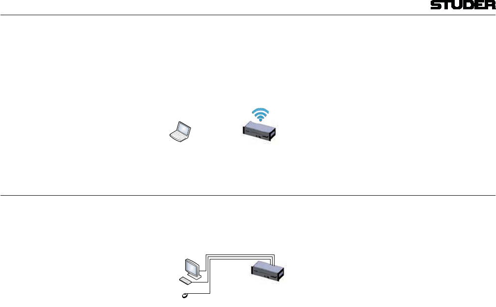
1.6 Hookup possibilites direct GUI Control
The simplest way of controlling the Micro Core is using the peripherial
interface where a screen and mouse and keyboard can be connected, without
any network in between.
OnAir Micro Base Unit
Screen with HDMI Input
USB Keyboard
USB Mouse
Note : Please pay attention that the external screen with HDMI input is able to show
the full image, and no ‘overscan’ is applied.
Micro Series
Micro Series 1-11
Document generated: 04.10.17 SW V1.2
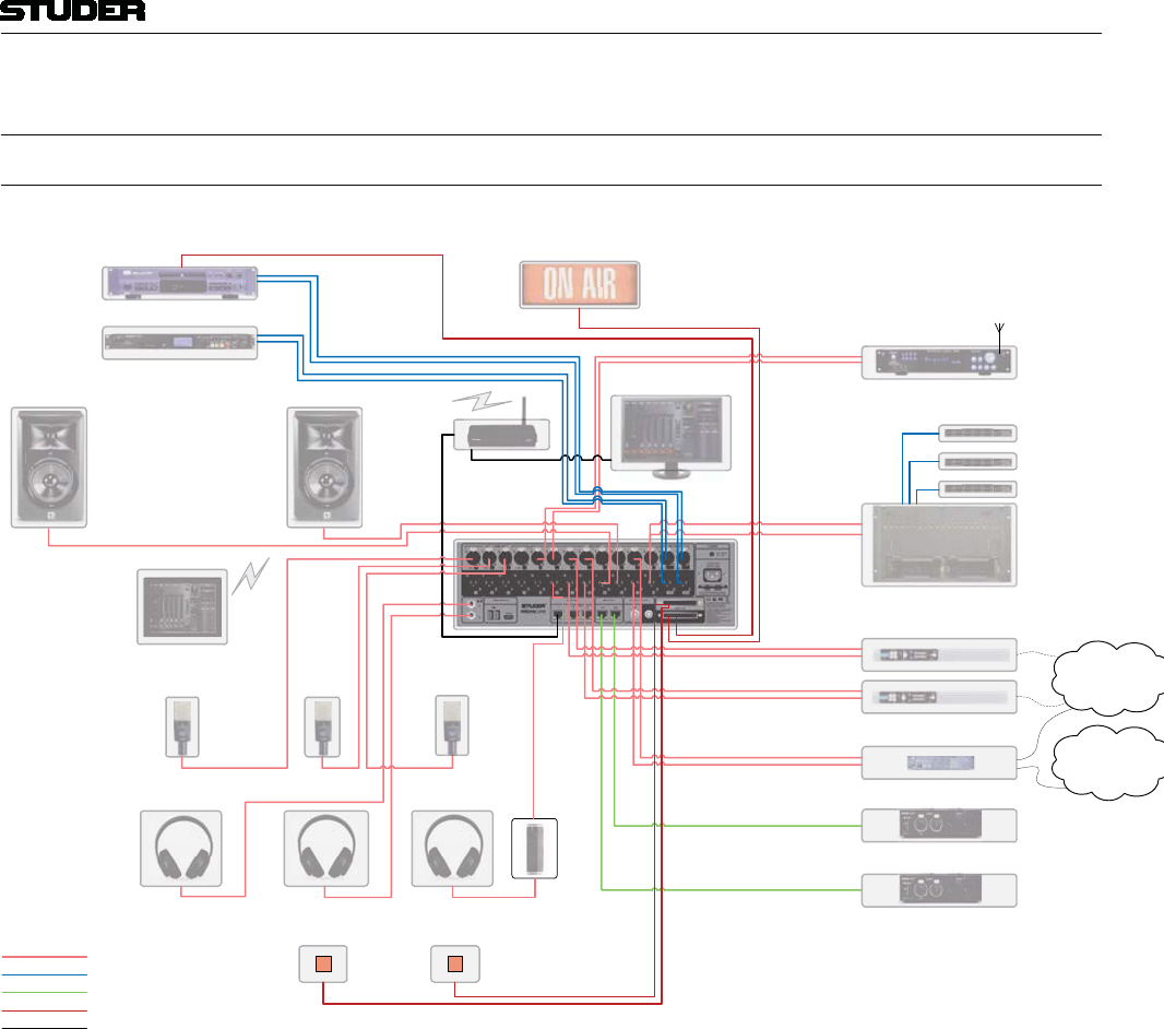
1.7 Applications
1.7.1 Hookup Diagram Application 1 - Radio OnAir Production
Dante Unit
Codec
Tel Hybrid 1
Intercom Matrix
Panel
Tuner
Flash Recorder / Player
CD Recorder / Player OnAir
Redlight
Control PC
WLAN Router
Tablet
Headphone Headphone Headphone
Mic
P
Pan
P
P
Pan
Pan
Pan
Pan
Pan
n
PanPan
l
el
l
l
el
el
el
el
e
el
el
Con
Con
Con
Con
Con
Con
on
Con
tro
tro
tro
tro
ro
tro
tro
ro
ro
tro
r
ro
o
o
r
lP
l
l P
l P
l P
P
l P
lP
l
lP
P
l
l
P
C
C
C
C
C
C
C
C
C
C
C
Tab
Tab
Tab
b
b
b
let
le
l
letlet
et
l
OnA
OnA
OnA
OnA
OnA
OnA
OnA
OnA
OnA
OnA
OnA
O
OnA
O
A
A
A
OnA
A
A
OnA
A
OnA
OnA
O
nA
O
O
OnA
OnA
OnA
A
O
A
O
i
ir
ir
i
r
r
r
r
i
i
ir
i
r
r
r
iri
ir
i
ir
Red
R
Red
Red
R
Re
Red
Red
Re
Red
Re
Re
Red
Red
e
Red
Red
Red
Red
R
e
Re
e
e
e
Red
R
Re
Re
e
R
Re
lig
lig
l
ig
ig
ig
ig
ig
ig
ig
ig
lig
ig
ig
l
ig
ig
ig
g
ig
g
ig
g
ig
ig
ig
g
ht
ht
ht
ht
ht
ht
ht
ht
ht
h
ht
t
ht
ht
t
ht
ht
h
ht
ht
ht
ht
h
h
ht
h
h
h
h
t
ht
Tun
Tun
Tun
Tun
TunTun
n
n
Tun
Tu
T
n
n
n
n
T
Tu
Tun
Tu
Tu
n
T
un
n
n
Tu
Tu
Tun
n
n
n
n
e
e
e
e
er
er
e
er
er
e
r
e
er
er
er
er
e
r
er
er
r
r
e
e
W
W
W
WLA
WLA
WLA
W
W
W
W
W
W
W
W
W
WL
W
W
W
W
W
L
L
L
N R
N
N R
out
out
out
t
e
e
er
er
e
e
e
e
e
e
e
DanDan
Dan
Dan
Dan
D
D
an
n
a
te
te
te
te
te
te
te
t
Un
Uni
Uni
Uni
Un
t
t
t
Cod
CodCod
d
Co
od
Co
Co
C
C
C
C
Co
Co
C
C
Co
o
ec
e
ec
e
e
ec
ec
e
c
c
e
e
c
e
Tel
l
Te
Tel
Tel
T
Tel
Tel
Tel
Tel
Tel
Tel
Te
Te
Te
Tel
Te
Tel
e
el
e
l
l
T
T
Tel
T
T
T
T
T
Tel
T
T
T
T
T
T
T
e
el
l
T
Hy
Hy
Hy
Hy
Hy
Hy
Hy
Hy
Hy
Hy
H
Hy
Hy
Hy
Hy
Hy
H
Hy
Hy
H
Hy
H
H
y
H
Hy
Hy
H
y
y
y
bi
bi
bri
bri
bri
d
d1
d 1
d 1
d1
MicMic
Mi
M
Mic
Mic
Mi
M
Mi
Mic
Mic
M
Mi
M
M
Mic
M
M
Mic
Mic
M
M
M
M
M
M
M
M
Mi
M
i
Hea
Hea
Hea
H
ea
e
Hea
Hea
e
Hea
Hea
Hea
Hea
Hea
ea
Hea
Hea
e
ea
a
dphdph
p
p
one
one
one
one
one
one
one
one
ne
ne
one
one
one
one
one
e
n
n
one
o
n
n
n
n
n
Hea
Hea
Hea
Hea
Hea
Hea
Hea
Hea
Hea
Hea
Hea
Hea
H
Hea
Hea
e
Hea
Hea
e
H
H
a
dphdph
dph
p
one
one
on
n
on
on
on
one
n
n
n
one
on
o
on
on
on
on
on
on
on
n
on
n
HeaHea
ea
e
ea
ea
ea
ea
ea
ea
ea
ea
e
ea
ea
e
ea
ea
ea
dph
dph
dph
d
d
d
d
d
one
one
one
one
one
one
one
e
e
one
e
e
one
one
e
one
n
one
e
one
one
n
e
Fla
Fla
Fla
la
l
la
a
a
h
h
h
sh
sh
sh
sh
sh
Rec
Rec
Rec
c
c
c
c
or
ord
o
ord
ord
ord
d
o
or
ord
ord
d
ord
ord
r
d
o
o
or
o
d
d
r
e
e
e
e
er
er
er
r
e
e
e
e
e
r
e
e
e
e
er
/ P/ P
P
/P
/ P
/ P
/ P
/P
P
P
P
P
P
P
/ P
P
P
P
P
P
P
P
P
P
P
P
P
P
P
P
P
P
P
P
P
P
lay
lay
lay
ay
lay
lay
ay
lay
lay
l
a
y
ay
y
lay
la
l
a
ay
ay
a
a
a
a
l
a
a
a
a
a
a
a
y
lay
lay
a
a
l
l
a
a
a
a
lay
l
a
a
y
a
y
er
erer
e
e
e
e
e
e
CD
CD
CD
CD
CD
CD
CD
C
CD
D
D
D
CD
CD
C
CD
CD
CD
CD
CD
CD
D
D
Rec
Rec
Rec
Rec
Rec
Rec
Rec
ec
Rec
c
c
Rec
Rec
ec
Rec
ec
ec
Rec
Rec
Rec
Rec
R
Re
e
ord
ord
ord
ord
ord
ord
o
d
ord
o
ord
o
ord
ord
rd
d
d
er
er
er
er
e
e
r
e
er
e
e
r
e
/ P
/ P
/ P
P
P
/ P
/P
/ P
P
P
P
P
P
/ P
P
P
/P
P
P
/
/ P
P
P
/ P
P
P
P
P
/
/
P
laylay
lay
lay
lay
lay
la
lay
lay
lay
ay
lay
lay
lay
lay
ay
lay
ay
lay
lay
ay
y
lay
lay
la
ay
lay
a
la
er
er
er
er
er
er
er
er
er
er
er
er
er
e
e
e
e
r
r
e
e
e
r
r
r
r
Int
Int
erc
om
m
Mat
Mat
rix
rix
Tel Hybrid 2
Mic Mic
DJ GUEST 1 GUEST 2
Dante Unit
Analogue Audio
Digital Audio
Dante
GPIO
Ethernet
PSTN
Panel
Panel
Internet
HP
AMP
Faderstart
Mi
Mic
Mic
M
M
Mic
Mi
Mi
M
Mic
i
Mic
Mi
Mic
M
M
Mic
Mic
M
M
M
M
M
i
M
M
M
M
M
Mi
c
M
Mic
Mic
Mi
M
Mic
Mic
Mic
M
Mi
Mic
Mic
M
Mi
M
M
M
M
M
Mic
M
M
M
M
M
M
M
M
Tel
Te
Tel
Tel
Tel
Tel
Tel
Tel
Te
T
T
Te
Tel
Tel
Tel
e
el
e
e
l
Tel
T
Tel
T
T
T
Tel
Tel
T
Tel
T
T
T
T
el
el
T
Hy
Hy
Hy
Hy
Hy
Hy
Hy
H
Hy
H
Hy
H
Hy
Hy
Hy
Hy
Hy
Hy
Hy
Hy
H
H
Hy
H
y
y
bi
bi
bri
bri
bri
d2
d2
d 2
d 2
d2
DanDan
Dan
Dan
Dan
D
D
an
a
an
te
te
te
te
te
te
e
e
t
Un
Uni
Uni
Uni
Un
t
t
t
Pan
Pan
Pan
Pan
Pan
Pan
Pan
Pan
Pan
n
el
el
el
el
el
el
el
el
e
Pan
Pan
P
P
Pan
Pan
Pan
Pan
Pan
n
Pan
el
el
l
l
el
el
el
el
e
el
TB Button TB Button
CR Mon
Speaker
CR
R
R
R
R
R
R
R
Mon
MonMon
M
Mo
M
M
M
M
M
M
M
M
Mo
Mo
Mo
Mo
o
Spe
Spe
Spe
Spe
Spe
Spe
Sp
Spe
pe
pe
pe
pe
e
e
p
p
p
ake
ake
ak
ake
ake
ke
ake
ake
ake
ake
a
ke
ke
ke
a
a
a
a
a
a
e
ke
a
ke
a
r
r
r
r
r
r
r
CR Mon
Speaker
CR
R
R
R
R
R
R
Mon
MonMonMo
M
Mo
M
M
M
M
M
M
M
Mo
Mo
o
o
o
Spe
Spe
Spe
Spe
Spe
Spe
Spe
pe
pe
pe
pe
e
e
e
p
p
ake
ake
a
ake
ake
ke
akeake
a
ke
ak
ke
ke
ke
a
a
a
a
a
ke
a
ke
a
a
k
r
r
r
r
r
r
r
r
Micro Core
The diagram above shows an example of how the Micro Core could be con-
nected in a typical OnAir Radio production environment.

Micro Series
1-12 Micro Series Document generated: 04.10.17
SW V1.2
1.7.2 Hookup Diagram Application 2 - TV OnAir Production
R 128
Meter
Intercom Matrix
Panel
WLAN Router
Tablet
Pan
P
Pan
P
P
Pan
Pan
Pan
Pan
Pan
an
Pan
el
l
el
l
l
el
el
el
el
e
el
Tab
Tab
Tab
b
b
b
let
le
et
letlet
l
W
W
WLA
WLA
W
W
W
W
W
W
W
W
W
WLA
W
L
L
L
L
N R
N
N R
out
out
out
t
e
e
er
r
e
e
e
e
e
e
e
e
Int
Int
erc
om
m
Mat
Mat
rix
rix
PRESENTER
GUEST 1
GUEST 2
Analogue Audio
Digital Audio
Dante
GPIO
Ethernet
Panel
Panel
P
Pan
Pan
Pan
Pan
Pan
Pan
Pan
Pan
Pan
an
l
el
el
el
el
el
el
el
el
e
P
Pan
P
P
Pan
Pan
Pan
Pan
Pan
an
Pan
Pan
l
el
l
l
el
el
el
el
e
el
el
CR Mon
Speaker
CR
R
R
R
R
R
R
R
Mon
Mon
Mon
M
M
Mo
M
Mo
M
M
M
M
M
Mo
M
Mo
Mo
o
Spe
Spe
Spe
Spe
Spe
pe
pe
Spe
Spe
pe
pe
pe
e
e
e
pe
akeake
ake
ake
ake
ke
ake
ake
ake
ake
ak
ke
ke
ke
a
a
a
ke
ke
ke
ak
a
ak
a
r
r
r
r
r
r
r
CR Mon
Speaker
CR
R
R
R
R
R
R
R
Mon
Mon
Mon
M
Mo
M
Mo
M
M
M
M
M
Mo
M
Mo
Mo
o
Spe
Spe
SpeSpe
Spe
Spe
Spe
Spe
Spe
pe
pe
pe
e
e
e
pe
ake
ake
ake
akeake
ke
ake
ake
ake
ake
ak
ke
ke
ke
a
a
a
ke
ke
ke
a
a
r
r
r
r
r
r
r
r
Micro Core
RF Receiver
R
R
RF
RF
R
R
R
R
F
Rec
Rec
RecRec
Rec
Rec
Rec
e
ec
Rec
ec
ec
ec
c
ec
ec
ec
c
c
e
ec
e
eiv
e
eiv
eiv
e
e
e
i
iv
e
ei
e
e
e
e
er
er
e
er
er
r
er
er
er
e
r
r
r
r
r
r
r
r
r
e
r
r
r
RF Receiver
R
R
RF
RF
R
R
R
R
F
Rec
Rec
RecRec
Rec
Rec
Rec
e
Rec
c
ec
ec
ec
c
ec
ec
ec
c
c
e
ec
e
eiv
e
eiv
eiv
e
e
e
e
i
iv
ei
e
e
e
e
er
er
e
er
er
er
er
r
r
r
r
r
e
er
r
r
er
r
r
r
r
e
r
r
r
RF Receiver
R
R
RF
RF
R
R
R
R
F
Rec
Rec
RecRec
Rec
Rec
ec
ec
Rec
c
c
ec
ec
c
ec
ec
ec
c
c
e
ec
e
eiv
e
eiv
e
e
eiv
eiv
i
e
e
ei
e
e
e
e
er
e
er
er
r
er
r
r
r
r
e
er
er
r
r
r
er
r
e
e
r
r
r
RF
MIC
RF
RF
RF
R
F
F
RF
RF
RF
F
F
R
R
F
F
RF
R
R
R
R
F
R
R
M
M
M
M
M
MIC
MI
MI
MI
M
M
M
M
M
M
M
M
M
MI
MI
I
I
I
RF
MIC
RF
RF
RF
R
F
F
RF
RF
RF
F
F
R
R
F
F
RF
R
R
R
R
F
R
R
M
M
M
M
MI
MIC
MI
MI
M
M
M
M
M
M
M
M
M
M
MI
MI
I
I
I
RF
MIC
RF
RF
RF
R
RF
RF
F
F
R
R
R
F
F
F
RF
R
R
R
R
F
R
R
R
M
M
M
M
MI
MIC
MI
MI
M
M
M
M
M
M
M
M
M
M
MI
I
MI
MI
I
I
I
IEM Transmitter
I
EM
E
EM
EM
EM
EM
EM
EM
EM
EM
EM
EM
M
I
M
M
EM
M
M
M
M
M
M
M
E
M
M
M
M
M
E
M
M
Tr
Tr
Tr
Tr
Tr
Tr
Tr
r
Tr
r
r
ans
ans
ans
an
an
an
an
ans
s
an
ans
a
an
n
n
n
n
s
s
s
ans
an
n
s
n
ans
s
n
n
s
mit
mit
mit
mitmit
t
mit
mit
mit
it
mit
mit
it
mit
m
m
m
m
m
t
m
t
t
ter
ter
ter
ter
t
ter
t
r
t
r
te
te
e
ter
te
te
t
t
te
te
t
te
te
te
e
r
e
t
t
t
e
e
r
t
te
t
t
IEM
IEM
E
EM
EM
M
M
M
EM
M
IE
M
M
M
M
M
M
M
M
M
M
M
M
M
M
M
M
M
M
M
M
M
M
M
M
M
M
M
R
R
R
R
R1
R1
R 1
R
1
R1
1
R
R 1
R
1
R
1
R
R 1
1
R 1
1
R
R
1
1
R
R
1
R
R
28
28
2
28
8
8
2
28
28
8
8
8
2
2
2
2
2
2
2
2
2
8
2
2
2
2
2
2
M
M
M
M
M
Met
Met
Met
Met
Met
Me
e
e
e
e
e
e
Met
Met
M
e
M
M
e
Met
M
e
e
e
Met
M
et
et
e
M
e
e
e
e
t
M
Me
e
t
e
e
e
e
e
e
e
e
e
e
e
r
r
r
e
e
e
e
r
e
e
e
e
e
e
e
e
e
e
Video Player 1
Video Player 2
Video Player 3
OnAir
Redlight
OnA
OnA
OnA
OnA
OnA
OnA
OnA
O
OnA
OnA
O
O
nA
A
OnA
A
OnA
A
A
OnA
OnA
OnA
OnA
OnA
OnA
OnA
O
OnA
OnA
O
O
A
OnA
OnA
O
i
i
ir
i
r
r
r
r
r
r
i
r
r
r
ir
i
r
r
r
Red
Red
Re
R
Red
Red
Red
Red
Red
Re
e
Red
Re
Re
Red
R
Re
Re
Re
e
Red
e
e
Re
d
d
Red
Re
lig
lig
lig
ig
ig
ig
ig
ig
ig
ig
lig
lig
ig
g
g
ig
ig
ig
ig
g
ig
g
ig
g
l
g
g
ig
ig
g
g
g
ht
ht
ht
ht
h
h
ht
hth
ht
ht
t
t
ht
t
ht
h
ht
ht
ht
h
ht
ht
t
ht
h
t
t
Studio
LS
Stu
StuStu
Stu
Stu
t
t
t
t
St
t
S
tu
u
u
u
u
u
di
di
dio
dio
d
didi
dio
diodio
di
dio
i
d
di
d
d
d
d
LS
LS
LS
LS
LS
LS
LS
LS
L
LS
L
S
L
LS
LS
L
L
Word Clock
Program Embedder
STUDIO
Control PC
Con
ConCon
Con
on
Con
Con
Con
tro
tro
tro
tro
r
ro
tro
o
tr
ro
ro
tro
tro
r
ro
r
ro
l
l P
l
l P
l P
P
l P
lP
l
lP
P
l
lP
P
C
C
C
C
C
C
C
C
C
C
C
C
Master Clock
Mas
Mas
Mas
Ma
M
Ma
a
a
s
ter
e
ter
t
e
t
ter
t
t
t
t
Cl
Cl
Cl
C
Cl
Cl
Cl
C
ock
ock
ock
oc
oc
oc
o
ck
c
ock
c
oc
o
c
oc
Vi
Vi
V
Vid
id
d
d
d
d
V
d
d
d
d
d
Vid
Vid
Vid
Vid
Vid
d
VidVid
V
Vid
Vid
eo
eo
eo
eo
eo
eo
e
eo
o
eo
Pl
Pl
Pl
P
Pl
l
Pl
P
Pl
Pla
Pla
Pla
la
Pla
Pla
P
Pla
la
Pla
yer
yer
yer
yer
yer
yer
yer
yer
yer
1
1
1
1
1
1
1
1
1
1
1
1
1
1
1
1
V
V
Vi
V
Vid
Vid
id
d
d
d
d
d
d
Vi
V
d
d
d
id
d
d
Vi
Vid
V
Vid
Vid
Vid
V
Vid
Vid
Vid
eo
eo
eo
eo
eo
e
eo
eo
eo
eo
Pla
Pl
Pl
Pl
Pla
l
Pla
Pl
Pla
Pla
P
P
Pla
P
a
P
Pla
Pla
P
Pla
Pla
P
l
Pla
la
a
yer
y
yer
ye
yer
yer
er
yer
yer
yer
yer
yer
y
2
2
2
2
2
2
2
2
2
2
2
2
2
2
2
2
2
2
2
2
2
V
V
Vi
Vi
V
V
V
i
Vid
id
d
d
d
d
d
d
V
d
d
d
id
d
d
Vid
Vi
Vid
Vid
Vid
d
Vid
Vid
V
Vid
Vid
eo
eo
eo
eo
o
eo
e
eo
eo
eo
eo
eo
eo
Pla
Pla
Pl
Pl
Pla
Pla
l
Pla
P
l
Pl
P
Pla
Pla
Pla
PlaPla
P
la
la
a
y
yer
yer
ye
y
yer
yer
yer
yer
yer
yer
yer
yer
y
3
3
3
3
3
3
3
3
3
3
3
3
3
3
3
3
3
3
a
a
a
a
a
a
a
a
a
a
a
m Em E
m
m
m E
mE
m E
E
m E
m E
m E
mb
b
mb
be
e
e
mb
mb
mb
mbe
e
be
mbe
mb
m
m
mb
b
e
m
b
The diagram above shows an example of how the Micro Core could be con-
nected in a typical TV production environment.
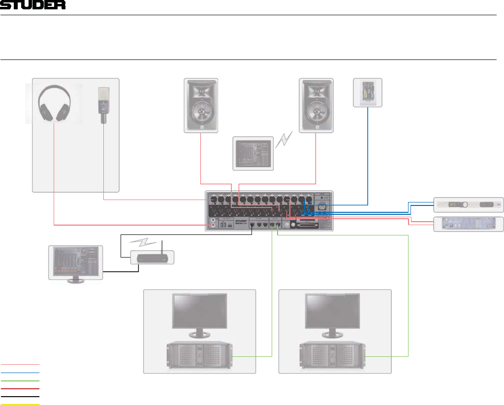
Micro Series
Micro Series 1-13
Document generated: 04.10.17 SW V1.2
1.7.3 Hookup Diagram Application 3 - Post Production
Analogue Audio
Digital Audio
Dante
GPIO
Ethernet
CR Mon
Speaker
CR
R
R
R
R
R
Mon
MonMon
M
Mo
M
M
M
M
Mo
M
M
M
M
M
M
Mo
M
o
o
o
o
Spe
Spe
Spe
Spe
Spe
Spe
Spe
pe
Spe
pe
pe
e
e
pe
e
pe
akeake
ake
ake
ake
ke
ke
akeake
a
ke
a
ke
ke
a
a
a
ke
ke
ke
a
r
rr
r
r
r
r
r
r
CR Mon
Speaker
CR
R
R
R
R
R
Mon
MonMon
Mo
M
Mo
M
M
M
M
M
M
Mo
M
M
o
o
o
o
Spe
Spe
Spe
Spe
Spe
Spe
pe
Spe
pe
pe
pe
pe
e
e
e
pe
akeake
ake
ak
akeake
ake
ake
ke
ak
ke
ke
ke
ke
a
a
a
a
ke
e
a
ke
a
a
a
r
r
r
r
r
r
r
r
r
Micro Core
Word Clock
Control PC
Con
Con
Con
Con
Con
Con
Con
tro
tro
tro
tro
ro
tro
ro
ro
o
o
ro
r
r
r
r
tro
l
l
l
l P
lP
lP
P
P
P
l P
l P
lP
l
l
lP
l
C
C
C
C
C
C
C
C
C
C
C
C
R 128
Meter
R
R
R
R
R1
R1
R1
R 1
R 1
1
1
1
R
1
1
R
1
R
R
R
1
28
28
2
28
8
8
8
2
28
2
2
2
2
8
2
2
2
2
2
2
2
2
2
2
2
M
M
M
MM
M
M
Met
Met
M
e
e
e
e
Me
Met
Met
Met
M
e
M
Met
M
M
M
M
e
et
t
Met
e
Me
e
e
Met
e
e
et
et
e
t
M
e
e
e
e
e
e
e
e
e
e
er
r
r
e
e
e
e
e
e
e
e
e
e
e
e
e
e
e
e
e
e
e
e
e
DAW 1 DAW 2
WLAN Router
W
W
W
WLA
W
W
W
W
W
W
W
W
W
W
W
W
W
WL
W
WL
W
W
W
W
N R
N
out
out
ut
e
e
er
e
e
e
e
e
e
e
e
e
e
Tablet
Tab
Tab
Tab
b
b
b
le
let
et
letlet
l
l
Voice Over
Booth
DAW
W
DAW
D
DAW
DA
AW
W
DAW
A
A
AW
DA
DAW
DAW
AW
1
1
1
1
1
1
1
1
1
1
1
1
DAW
AW
DAW
W
DAW
W
D
DA
AW
DAW
DA
A
AW
D
DAW
DAW
AW
2
2
2
2
2
2
2
2
2
2
2
2
Codec
CodCod
od
C
ec
c
c
c
ec
c
c
c
c
c
c
c
Reverb
Rev
ev
ev
ev
Re
Rev
Rev
ev
Rev
Rev
ev
ev
R
ev
ev
v
ev
Re
R
R
Rev
ev
Re
ev
ev
v
ev
v
Re
Re
erb
erb
erb
erb
erb
erb
erb
The diagram above shows an example of how the Micro Core could be con-
nected in a typical Post Production environment.

Micro Series
1-14 Micro Series Document generated: 04.10.17
SW V1.2
2 GUI OPERATION
The GUI operation concept of the Micro Series is organized in three levels :
L1 - Operations level
L2 - Options level
L3 - Configuration level
L1 The Operation level is the top page of the GUI. Here, all controls which are
needed for a DJ to run a live radio show are easily accessible.
L2 The Options level only shows the options of one specific channel. It is opened
by double-clicking (or touching) the channel’s label.
L3 The Configuration level is entered by using the Config button. Then the
Config view is shown, which consists of several pages.
In the following chapters, all three levels are described.
2.1 L1 - The operation level (for DJs)
2.1.1 Main Page
For basic DJ operation, all necessary control elements can be found on the
Main page of the GUI. The Main page consists of three sections :
Left section
Central section
Right section (Watch and Metering/Monitoring)
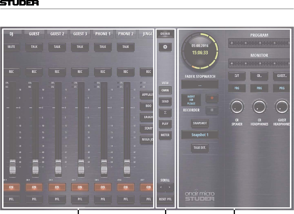
Micro Series
Micro Series 1-15
Document generated: 04.10.17 SW V1.2
Le t section Central section ight section
Left Section The left section of the GUIs operation view displays the control elements that
are selected by the view buttons in the central section. This section is the main
working surface for the DJ.
Central Section The section in the middle of the GUI provides the view buttons, elements for
navigation, the OnAir indication, as well as the button to access the mixer
settings.
Right Section The right section of the GUIs operation view displays control elements for
Watch, Recording, Snapshot handling, Metering and Monitoring
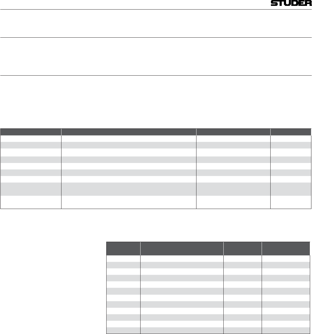
Micro Series
1-16 Micro Series Document generated: 04.10.17
SW V1.2
2.1.2 Mixer Channels
Before the channel view is explained, it is essential to understand the concept
of having different channel roles.
2.1.2.1 Channel Roles
All twelve DSP channels are identical. But every channel can be given a
specific “role”. The role links specific functionality and operating elements
to a channel, in order to make it capable of a specific task.
The following channel roles can more or less freely be used :
Channel Role Description Additional Buttons Specific Input
Default for a simple input channel, no special behaviour
DJ for a mic source located in the control room (CR) Mute
Guest for a mic source located in the control room (CR) Talk
Input for sends 1 the bus owner of a N-1 bus Talk
Input for sends 2 the bus owner of a N-1 bus Talk
Input for sends 3 the bus owner of a N-1 bus Talk
Input for sends 4 the bus owner of a N-1 bus Talk
Track for the input channel that is linked to the Track Player Next, Display Is linked to USB
In 3/4
Jingle for the input channel that is linked to the Jingle Player Jingle buttons Is linked to USB
In 1/2
Already in the factory-reset state of the mixer, the channels have different
roles.
Channel
Num er Channel ole a ter Factory- eset Channel La el Channel Source
1 DJ DJ MIC HQ MIC/LINE #1
2 Guest GUEST 1 HQ MIC/LINE #2
3 Guest GUEST 2 HQ MIC/LINE #3
4 Guest GUEST 3 HQ MIC/LINE #4
5 Input for sends 1 PHONE 1 ANALOG LINE #9
6 Input for sends 2 PHONE 2 ANALOG LINE #10
7 Jingle JINGLE USB 1/2
8 Track PLAYER USB 3/4
9 Default AES 1/2 AES 1/2
10 Default LINE 1/2 ANALOG LINE 5/6
11 Default LINE 3/4 ANALOG LINE 7/8
12 Default NET AES67/DANTE 1/2
Channel roles are configured in the Config View of a channel, under the
Source tab.
Depending on the channel role, the channel view can vary, because of addi-
tional buttons that need to be operatable.
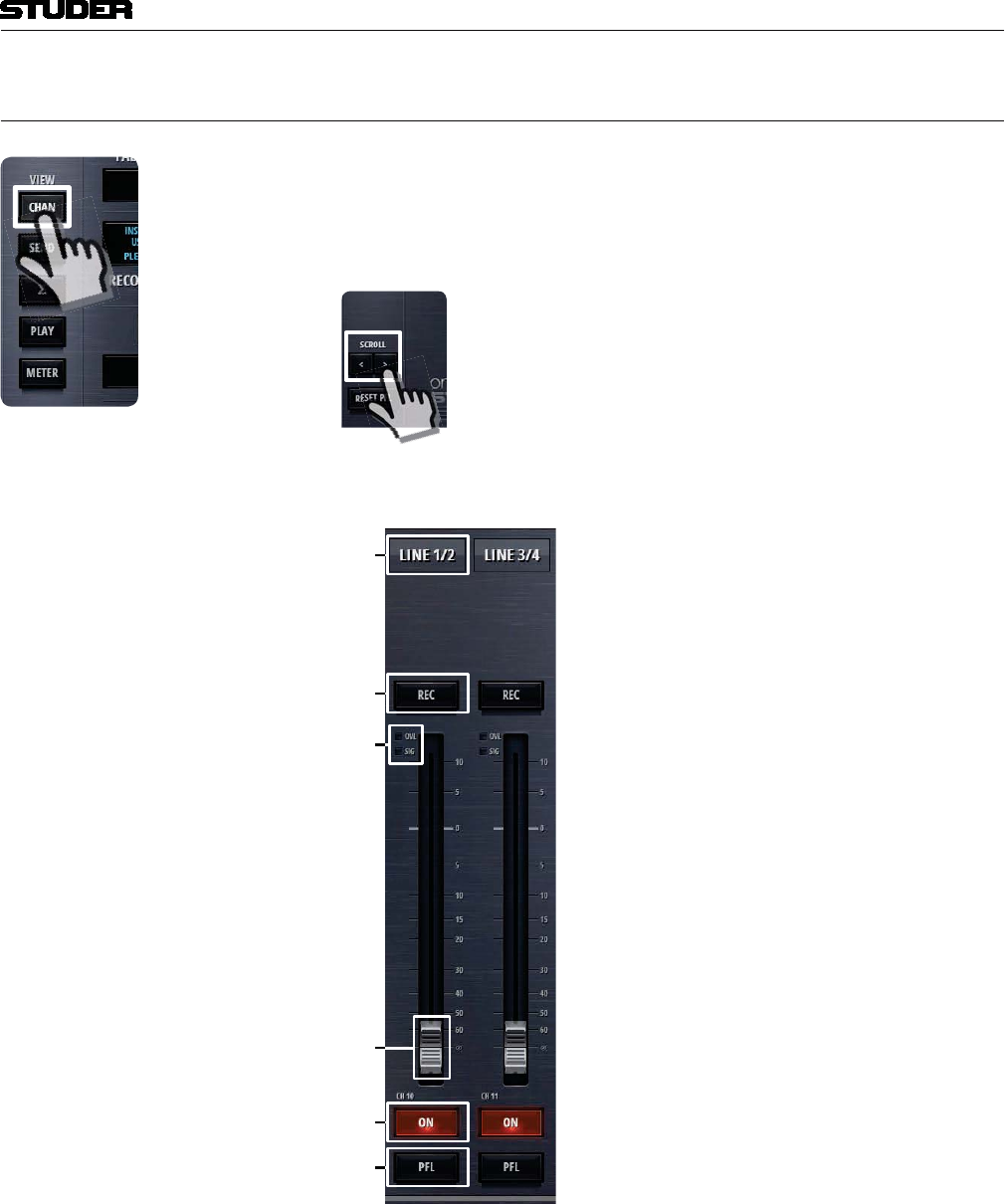
Micro Series
Micro Series 1-17
Document generated: 04.10.17 SW V1.2
2.1.3 Chan View
The channel view shows the faderstrips of the mixers input channels. All
twelve input channels are shown - by using the scroll buttons in the central
section the operator can navigate to the desired faderstrips. Also swiping can
be used on a touchscreen to navigate between the faderstrips.
The operating elements that are common to all channels are these (channel role “Default”) :
1
2
[1] Label The channel label display shows the channels name. This name can be entered
in the Options page of the channel. The labels background changes from grey
to blue, when the channel is ‚On-Master‘.
[2] Rec button The Rec button assigns a channel to the record bus.
[3] OVL Indicator The overload indicator is used to indicate analogue input clipping (A/D con-
verter), which means overload is never illuminated for digital sources. For
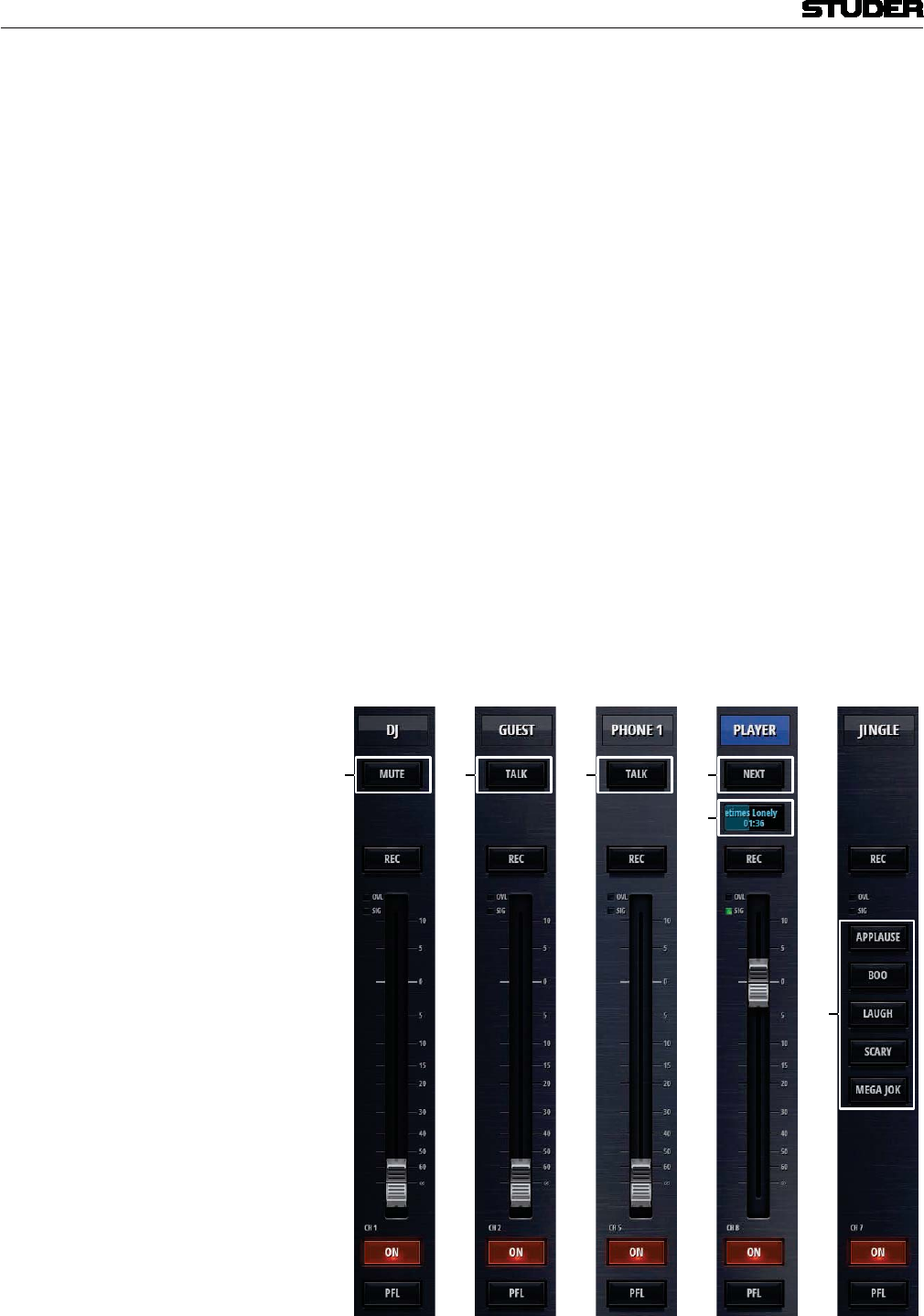
Micro Series
1-18 Micro Series Document generated: 04.10.17
SW V1.2
channels with analogue inputs, OVL is illuminated as soon as the input level,
before input calibration, reaches 0dBFS.
[3] SIG Indicator The green signal indicator is illuminated as soon as the signal is > -40dB. The
signal is captured after the INPUT processing block and therefore it is also
influenced by the analogue gain as well as the digital input calibration of the
channel.
[4] Fader The channel fader. It can be operated by mouse or touch. The mousewheel can
also be used to operate the fader when hovering the mousepointer anywhere
over the fader area.
[5] On button The On button activates the channel. When the fader is open, the On button
toggles the channel ‚on-air‘ and ‚off-air‘.
[6] PFL button The PFL button allows the operator to pre- listen to this channel even if the
fader is closed or the channel is not switched to ‚On‘. PFL stands for PreF-
adeListening. The Reset PFL button in the central section releases all channels
from PFL.
The channel of other roles than “Default” have additional buttons :
Role : DJ Guest Input for sends Track Jingle
1 2 2

Micro Series
Micro Series 1-19
Document generated: 04.10.17 SW V1.2
[1] Mute button The Mute button is intended for the use as a cough-button. It is only available
for channels of the role DJ.
[2] Talk button The Talk button allows the DJ to talk either to a Guest via the Guest’s head-
phone monitor - or to a N-1 output of a channel of the role “Input for sends”.
[3] Next button The Next button allows to change to the next audio file of the current playing
playlist. For details please see chapter 2.1.6.1 Track Player Operation.
[4] Status Display The Status Display of the Track Player Channel shows the name of the current
title, as well as a progress bar and the current playing time.
[5] Jingle buttons The Jingle buttons are used to play specific Jingles from the Jingle channel.
More Jingle buttons can be found in the Play view.
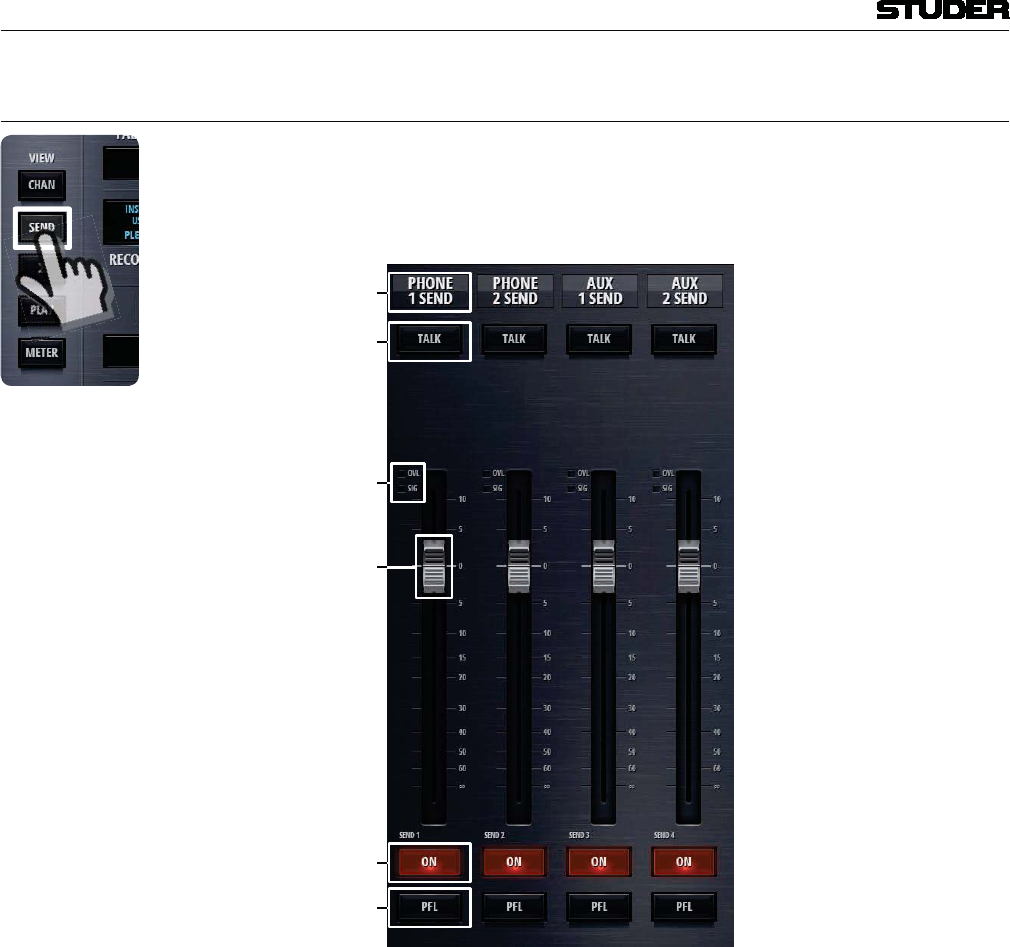
Micro Series
1-20 Micro Series Document generated: 04.10.17
SW V1.2
2.1.4 Send View
The send view shows the mixers four send channels. Each of these four chan-
nels can either be an Aux or N-1 send. Here, the send master faders can be
operated.
[]
[2]
[]
[]
[]
[]
[1] Label The label display shows the send channels name. This name can be entered
in the Options page of the send channel.
[2] Talk button This button can be used to talk to the output of this send channel.
[5] SIG Indicator The green signal indicator is illuminated as soon as the signal on the send bus
is > -40dB. The signal is captured before the send fader.
[6] Fader The send fader. It can be operated by mouse or touch. The mousewheel can
also be used to operate the fader when hovering the mousepointer anywhere
over the fader area.
[7] On button The On button activates the send channel.
[8] PFL button The PFL button allows the operator to pre- listen to this channel even if the
fader is closed or the channel is not switched to ‚On‘. PFL stands for PreF-
adeListening. The Reset PFL button in the central section releases all channels
from PFL.
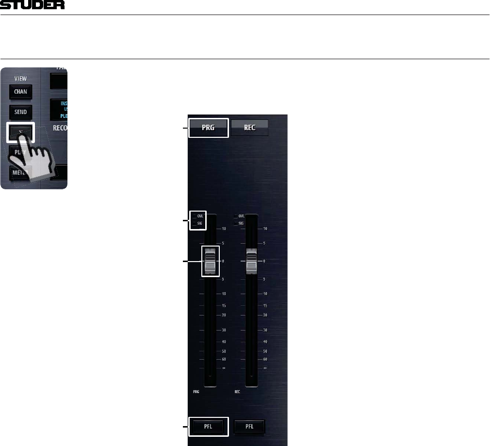
Micro Series
Micro Series 1-21
Document generated: 04.10.17 SW V1.2
2.1.5 Sum View
The sum view shows the master faders of the program (PRG) - as well as the
recording (REC) bus .
1
[1] Label The label display shows the bus name. This name can be entered in the Options
page of the bus.
[5] SIG Indicator The green signal indicator is illuminated as soon as the signal is on the send
bus is > -40dB. The signal is captured before the bus fader.
[6] Fader The bus fader. It can be operated by mouse or touch. The mousewheel can
also be used to operate the fader when hovering the mousepointer anywhere
over the fader area.
[8] PFL button The PFL button allows the operator to pre- listen to this bus even if the fader is
closed. PFL stands for PreFadeListening. The Reset PFL button in the central
section releases all channels from PFL.
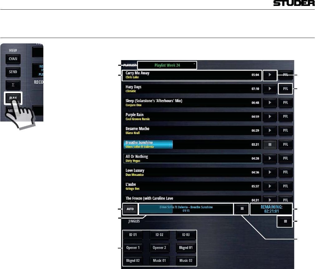
Micro Series
1-22 Micro Series Document generated: 04.10.17
SW V1.2
2.1.6 Play(er) View
The play(er) view changes the left section to show the player window.
2
1
1
[1] Media Media and playlist selection.
[2] Title bars The title as well as the name of the artist is listed here. The blue progress bar
shows the current position in the title. Also the total playing time is displayed
at the end of the bar.
[3] Play mode Automatic or Manual player mode. The Play Mode defines the behaviour
when on-air playback of a file reaches its end.
Manual If the file is played to its end before the Track Player Channel is closed or
playback is stopped by the user, the Track Player Channel is turned to off.
Auto If a file is played to its end before the Track Player Channel is closed or play-
back is stopped by the user, playback of the currently selected audio file starts
automatically from begin. In case of a playlist, the next file of the playlist
starts automatically from begin. This allows playing all files of the selected
playlist without further user action.
[4] Currently playing title display Displays the currently playing title as well as the current playing time. The
blue progress bar shows the current position in the title.
[5] Play/Stop buttons Titles can be played and stopped directly with these dedicated play/stop but-
tons in the Player View.
Clicking or touching the Play button turns the Track Player Channel to On

Micro Series
Micro Series 1-23
Document generated: 04.10.17 SW V1.2
and starts playback of a dedicated file from begin, regardless if any file is
already playing or not. Note, that the fader must be open when using Play in
order to make sure playback reaches program-, record and send buses. If the
Stop button of a currently playing file is pressed, playback stops, the Track
Player Channel is turned to Off.
[6] PFL buttons The PFL button is used to pre-listen the current selected audio file.
As long as the Track Player Channel is not open :
Note, that PFL is automatically deactivated, when the Track Player Channel
reaches On-Master status.
If the file is played to its end before PFL is deactivated by the user, playback
stops and PFL is turned off.
[7] Remaining time display Here, the remaining time of the playlist is displayed.
[8] Stop button Titles can be stopped directly with this global stop button.
[9] Jingle buttons The Jingle buttons are used to play specific Jingles from the Jingle channel.
Here in the Player view, nine buttons are shown, where in the channel view
depending on the size of the GUI, sometimes not all nine buttons can be
shown.
[10] Stop button Jingles can be stopped directly with this global stop button.
2.1.6.1 Track Player Operation
Clicking or touching onto the Media field, opens up the media dialog.
This list shows :
A playlist or an audio file can then be selected.
The following externally created playlists are supported :
File Extension Description
.wpl Windows Media Player Playlist
.m3u Multimedia Playlist
.pla Winamp Playlist
.pls Text Based Multimedia Playlist
And the following audio file formats are supported :
Format File E tension Description
Wave .wav uncompressed audio
AAC .aac lossy audio compression
MP3 .mp3 lossy audio compression
Ogg Vorbis .ogg lossy audio compression
AIFF .aif uncompressed audio
FLAC .flac lossless audio compression
The Track Player is able to play a selected audio file or the audio files of a
selected playlist.
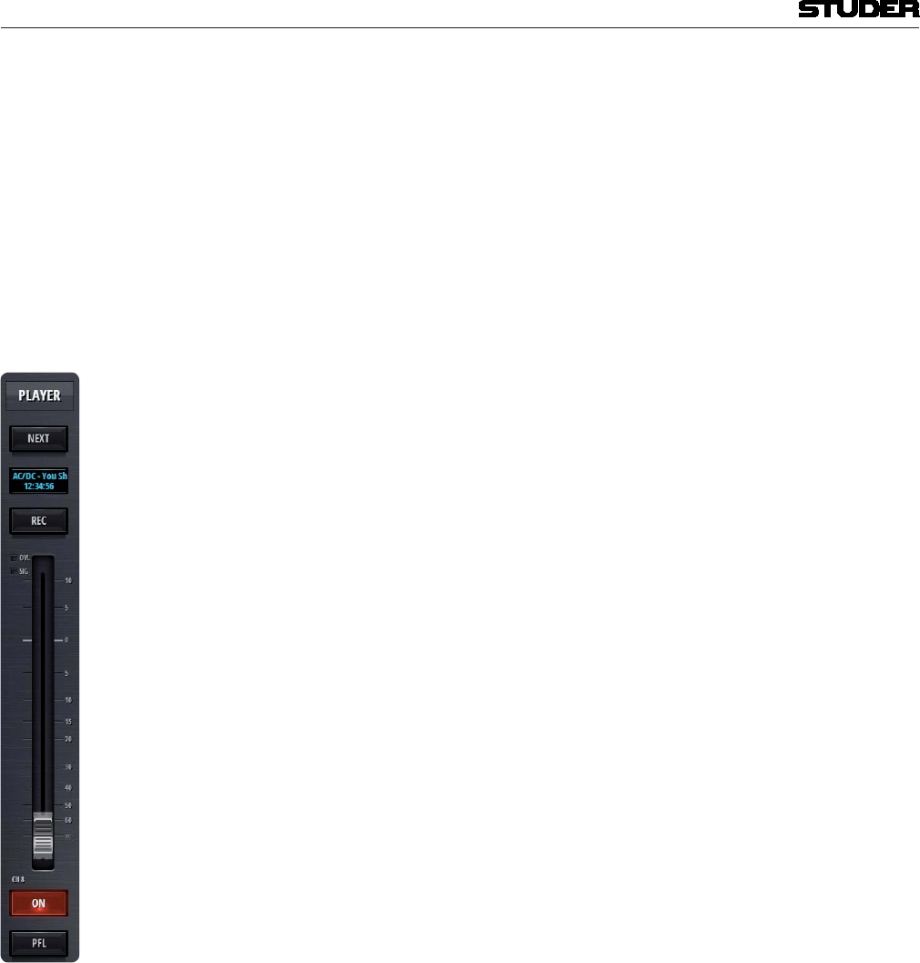
Micro Series
1-24 Micro Series Document generated: 04.10.17
SW V1.2
The files are played back via the channel with the role “track”.
The Track Player is controlled on Operation Level L1 of the Track Player
Channel through the following elements :
FaderStart To start the Track Player via FaderStart, the channel ON button must be active,
and the fader must be opened. Then, playback of the the currently selected
audio file or the next file in the playlist starts from begin.
Closing the Track Player Channel will stop playback and re-positions to the
file begin. In case of a playlist, the next file of the playlist will be positioned
to its begin.
This allows playing all files of the selected playlist just by opening and clos-
ing the fader, or by turning the channel ON and OFF.
Next button The Next button operation works similar as activating FaderStart , with the
the following difference - it can also be activated while a file is already play-
ing and it doesn’t stop playback. Therefore, the Next button function allows
playback of the next file of the playlist without the need of manually stopping
the currently playing file first.
Note, that the fader must be open when using the Next button in order to make
sure playback reaches program-, record and send buses.
The Next button function is defined as follows:
During Stop:
When the Next button is activated while no playback is in progress, the Track
Player Channel is turned to ON and playback of the currently selected audio
file or the next file of the selected playlist starts from begin.
During Playback:
When the Next button is activated while playback is in progress, the current
playback stops and playback of the next file of the selected playlist starts from
begin.
In case of a selected file instead of a playlist, the currently selected file restarts
playback from its begin.
PFL button When no track is playing, activating the Track Player Channels PFL button,
the playback of the currently selected audio file is started and the Track Player
Channel remains OFF. When a file is already playing, the Track Playe Chan-
nels PFL can be activated, but then playback of the file is not interrupted nor
will playback of this file be re-started.
Since there is only one instance of the Track Player, PFL of a track, while a
different track is currently playing is not possible!
When no file is playing, any desired audio file can be prelistened in the Play
View. This is done with the PFL button that is located at the and of each track
next to the play button.
Playing order Usually the audio files of a playlist are played in the order they are defined
by the list. Once a file is playing, there is a blue frame around the Title Bar
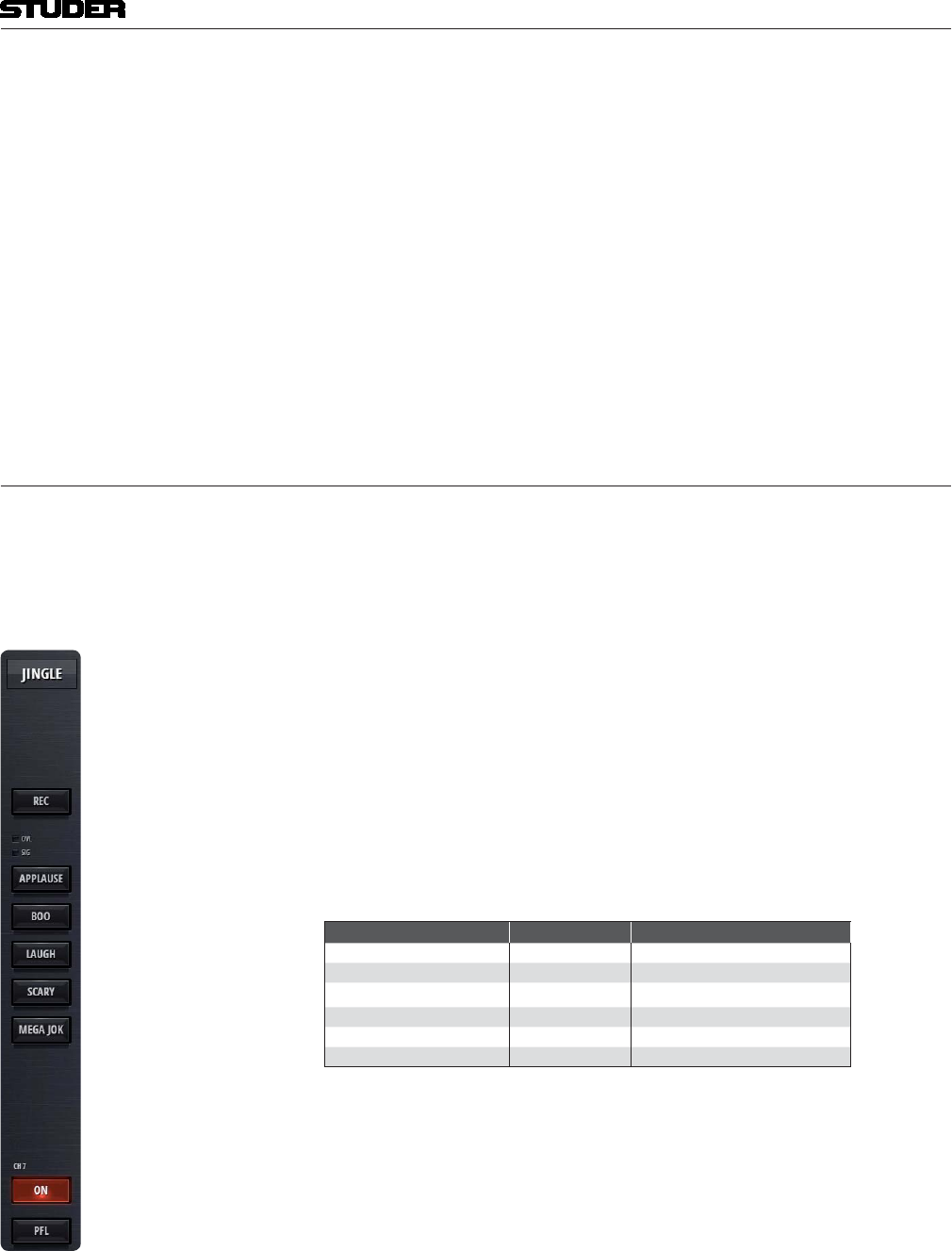
Micro Series
Micro Series 1-25
Document generated: 04.10.17 SW V1.2
of the file that will be played as next file.
‘next file to be played’ This file is marked as ‘next file to be played’.
Without any interference of the operator, this file will be played when the
current playing file has come to its end. If the operator decides, that a different
file should be played as next file, she/he can long-click/touch on any other
file in the playlist, whereupon the long-clicked file will be marked with the
blue frame and becomes the next file to be played.
The next file to be played from the playlist is defined as follows :
the playlist is automatically selected as the next file to be played. After
the last file from the playlist starts playback, the first file in the playlist is
automatically selected as the next file to be played.
2.1.6.2 Jingle Player Operation
The Jingle Player supplies stereo audio playback through the inputs USB 1/2.
Any channel that is configured to have these inputs as source is in the role
“Jingle Player” and is used to control the playback of the jingles.
Nine different jingle can be loaded which will then be available for playback
through nine direct access buttons.
Audio files can be assigned to jingle buttons through the following file name
conventions:
Jingle Player files must be located in the ‘Jingle’ folder of the USB storage
media.
The filename begins with the character “J” followed by a one- or two digits
button number 1..9 or 01...09.
The first eight characters of the filename are indicated on the jingle button.
If the filename is more than eight characters long, the surplus characters are
omitted.
The following audio file formats can be used for the Jingle Player :
Format File E tension Description
Wave .wav uncompressed audio
AAC .aac lossy audio compression
MP3 .mp3 lossy audio compression
Ogg Vorbis .ogg lossy audio compression
AIFF .aif uncompressed audio
FLAC .flac lossless audio compression
Example : J01_Logo 1.wav is the file that will be played when button 1 is pressed. The
button will be labeled “Logo 1”.
J2Applaus.wav is the file that will be played when button 2 is pressed. This
button will get the label “Applaus”.
The Jingle Player is controlled on Operation Level L1 of the Jingle Player
Channel through the following elements :

Micro Series
1-26 Micro Series Document generated: 04.10.17
SW V1.2
Only one jingle can be played at the time. Starting another jingle stops the
currently playing jingle and starts the next one.
button.
Starting
/Restarting a jingle Pressing a Jingle button triggers the following actions :
If PFL is active, the Jingle Player channel is set to OFF.
Stopping a jingle A currently playing jingle can be stopped by either turning the Jingle Player
Channel to OFF or pressing the STOP button in the Play View page.
Playback of a Jingle stops automatically at its end without any user action.
When playback is stopped, the Jingle Player Channel is automatically
switched to channel OFF.
Note 1 : If the Jingle Player Channel is set to ON, eventhough no Jingle is playing,
the Jingle Player Channel is On Air.
As in the GUI, there is no fader to this channel, the On Air state is simply
activated by the channel ON/OFF button.
Note 2 : There is a difference to Micro Series mixers with connected Micro Fader
modules. In the case of connected Micro Fader module, the Jingle Player
Channel can have a fader - which then also has an effect on the On Air state
of the Jingle Player Channel.
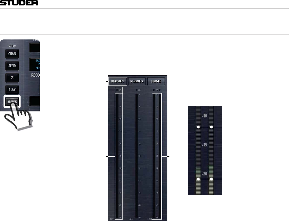
Micro Series
Micro Series 1-27
Document generated: 04.10.17 SW V1.2
2.1.7 Meter View
The meter view shows the meter bargraphs of all input channels. Navigation
is similar to navigating with the channel faders.
1
2
Pre Fader Signal Level
Post Fader Signal Level
[1] Label The label display shows the send channels name. This name can be entered
in the Options page of the send channel.
[2] OVL Indicator The overload indicator is used to indicate analogue input clipping (A/D con-
verter), which means overload is never illuminated for digital sources. For
channels with analogue inputs, OVL is illuminated as soon as the input level,
before input calibration, reaches 0dBFS.
[3] Mono Meter The meter of a mono input channel. The meter scale is digital with 0dBFS at
the top.
[4] Stereo Meter The meter of a stereo input channel. The meter scale is digital with 0dBFS at
the top.
Pre/Post level metering The level bargraph indicates pre- and post fader signal level at the same time.
The pre fader signal level is indicated in the background as a blue bar. The
post fader signal level is indicated in the foreground, covering the pre fader
signal.
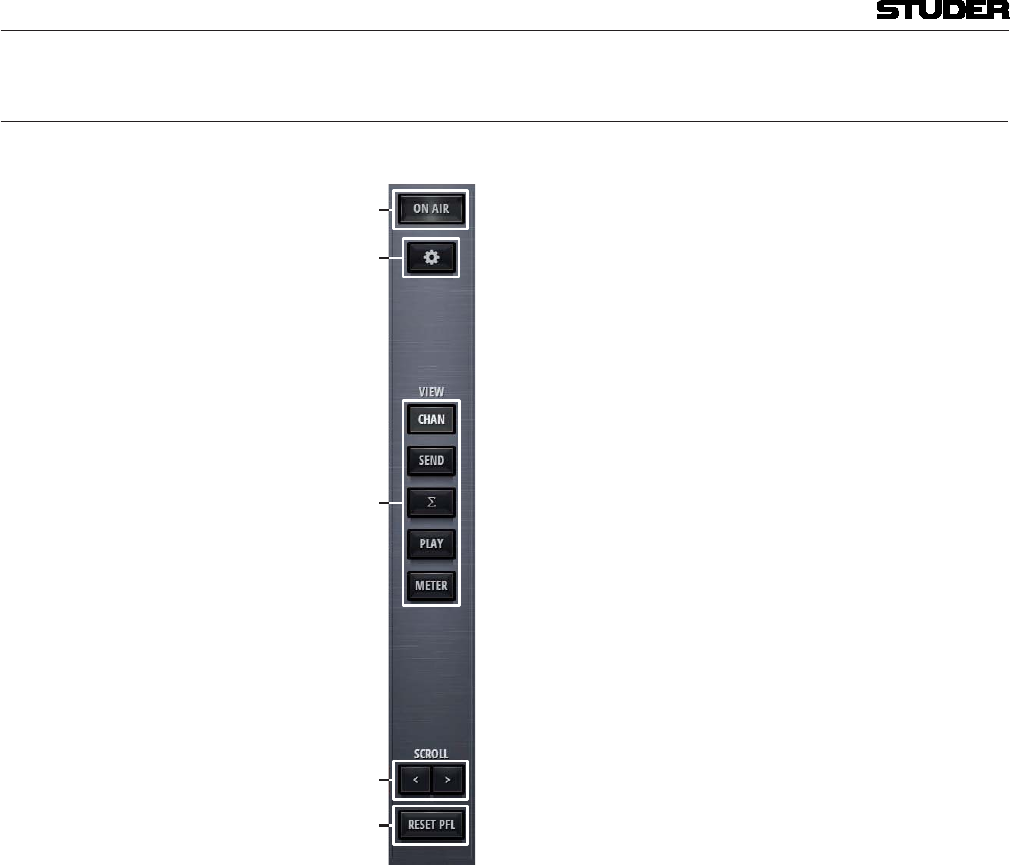
Micro Series
1-28 Micro Series Document generated: 04.10.17
SW V1.2
2.1.8 Central Section
The central section of the main page hosts the following control elements :
1
2
[1] On Air Red Light Indicator The On Air indicator is active when any of the input channels is on-air.
[2] Settings A click or touch on this button leads to the Settings page where the basic
configuration of the Micro Series is made.
[3] View buttons The five view buttons allow to select the control elements that will be shown
on the left section of the GUI.
[4] Scroll buttons The scroll left and the scroll right button allow the operator to navigate to the
desired faderstrips or meters.
[5] Reset PFL This button releases any PFL button which is currently active anywhere in
the mixer.
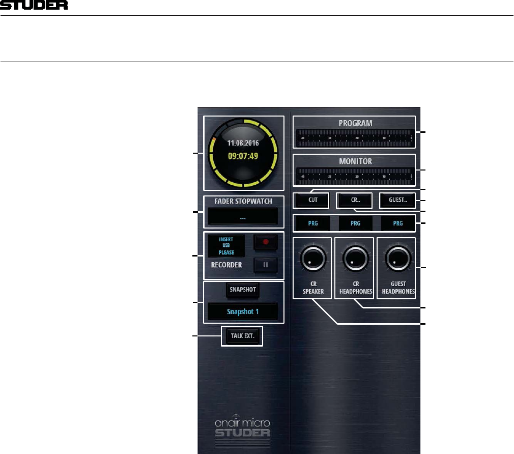
Micro Series
Micro Series 1-29
Document generated: 04.10.17 SW V1.2
2.1.9 Right Section
The right section of the main page hosts control elements for Watch, Record-
ing, Snapshot handling, Metering and Monitoring.
[]
[2]
[3]
[]
[]
[]
[]
[0]
[]
[]
[]
[]
[3]
[2]
[1] OnAir Watch The OnAir watch gives a permanent display of the current time and date. It
can be NTP synchronized.
[2] Fader Stopwatch The Fader stopwatch measures the channel-open time of the most recently
opened channel that is “On-Master”. Only channels of the role “DJ”, “Guest”
and “Input for Send” start the stopwatch.
When clicking or touching onto the display of the stopwatch, a countdown
time for the most recently opened channel can be entered. As soon as the time
reaches 00:00:00, the channel name will flash for five seconds. If the time
00:00:00 is entered as a countdown time, the stopwatch will count upwards
for as long as the channel is opened.
The display of the stopwatch also indicates the name of the currently mea-
sured channel. When in countdown mode, the countdown icon in the top right
corner of the display is shown.
[3] Recorder As a default, the REC bus is feeding the USB Recorder. So all channels that
are assigned to the REC bus are recorded as soon as a valid memory stick is
inserted and the record button is pressed. Details see chapter 2.1.9.1.
[4] User Snapshots The User Snapshot considers the fact that the Micro Series are designed as

Micro Series
1-30 Micro Series Document generated: 04.10.17
SW V1.2
a portable products to be used in different environments. Therefore the User
Snapshot contains all required settings of a broadcast session. User Snapshots
can be created, saved, loaded, renamed and deleted by the user at any time.
Details see chapter 2.1.9.2.
[5] Talk Ext. This button activates the external talkback. TB source and destination can be
configured. Details see chapter 2.1.9.3.
[6] Program meter The Program meter is displaying the audio level of the Program bus. The
headroom level and balistics can be configured. Details see chapter 2.4 -
Meter tab.
[7] CR Monitor meter The Monitor meter is displaying the audio level of the source which is cur-
rently chosen by the CR monitor. The headroom level and balistics can be
configured. Details see chapter 2.4 - Meter tab.
[8] Monitor Cut This button lets the operator manually cut the CR monitor. In addition, CR
cut is applied automatically when a channel of the role “DJ” or “Guest” gets
on-air.
[9] CR Monitoring Options This button opens the dialog to set the CR Monitoring Options. Details see
chapter 2.2.5.
[10] Guest Monitoring Options This button opens the dialog to set the Guest Monitoring Options. Details see
chapter 2.2.6.
[11] Source displays These three displays show the sources of the three different monitoring facili-
ties.
[12] CR Speaker level Lets the operator set the level of the CR monitor speakers
[13] CR Headphone level Lets the operator set the level of the CR headphones
[14] Guest Headphone level Lets the operator set the level of the Guest headphones
2.1.9.1 USB Recorder
1
2 At the moment an USB media is inserted into the Play/Rec USB port, a per-
formance test of the media is carried out. When the media’s performance is
sufficient, the LED next to the Play/Rec USB port turns green.
[1] Status Indication With a valid USB media inserted, this display shows the amount of free
memory of the inserted USB media. Below the free memory, the total amount
of the inserted media’s memory is shown in [GB].Then, there is a progress-
bar indicating the used memory of the USB storage media. Within the prog-
ress bar, the predicted remaining recording time is displayed in the format
hh:mm:ss.
[2] Recording buffer This thin bar shows the current usage of the recording buffer.

Micro Series
Micro Series 1-31
Document generated: 04.10.17 SW V1.2
[3] Record Button Starts the recording. When the recording is on pause, another click/touch onto
the Record Button restarts the recording and appends the recorded audio to
the current file.
While recording, the Status Indication display shows the name of the cur-
rently recorded file and the files current length.
[4] Pause/Stop Button A click/touch on this button pauses the recording. A second click/touch onto
this button stops the recording and the recorded audio is written to a file.
Where are the files stored ? By default, the recorded files are saved to the USB media into a folder auto-
matically created, named ‘Recordings’.
The files are also named automatically by the system. Time and date at the
start of the recording determine the file name : yyyymmdd-hhmmss.wav.
Record Source Selection The default source of the USB recorder is the REC bus. If desired, any other
bus can be assigned as the recording source. This can be set on the Bus options
page.
Off-Air Record Function Off Air Record is a convenient function for the operator to record a guest or
telephone interview in parallel to the program, where e.g. the radio automa-
tion or a playlist from the track player is playing.
The Off Air Record function handles all required bus assignments changes
of the recording channels automatically in the background and the operator
doesn’t have to care about.
Scenario guest interview : The operator wants to record a guest interview where he needs the DJ mic
and a guest mic. Activating the Off Air Record function (REC) of the DJ- and
guest mic automatically
as long as Off Air Record is active.
When terminating Off Air Record, the original monitoring sources and bus
assignments as defined in the channel- or bus options pages are restored.
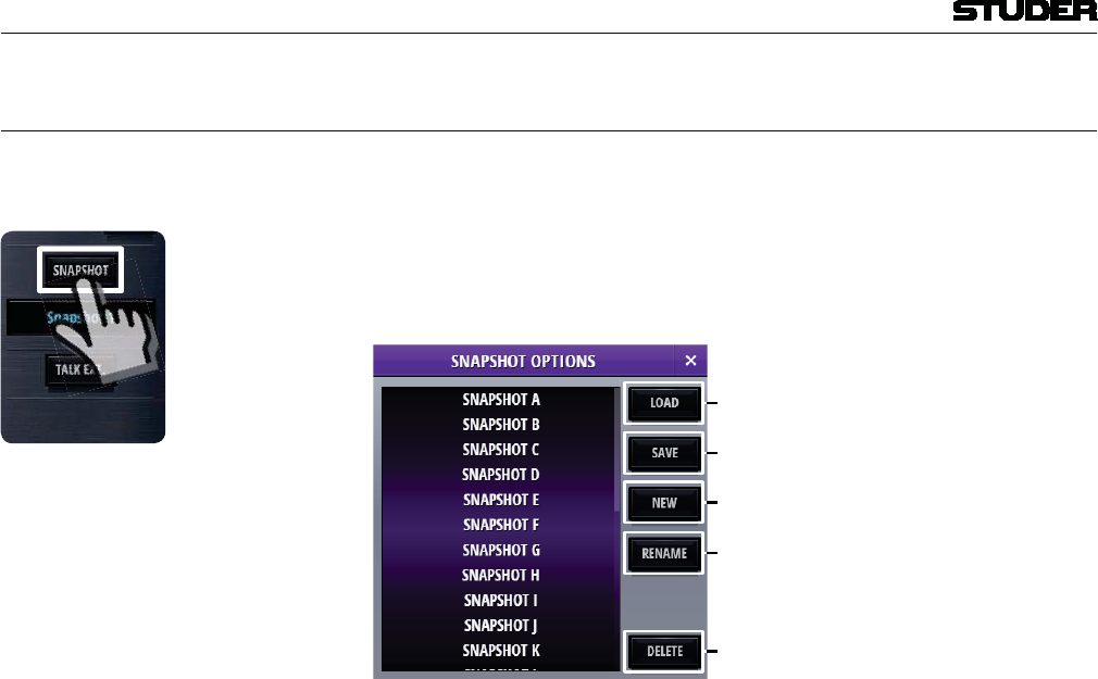
Micro Series
1-32 Micro Series Document generated: 04.10.17
SW V1.2
2.1.9.2 User Snapshots
A User Snapshot contains all parameters of the system, except from the
parameters of the Settings section.
By Clicking/touching the Snapshot button, the snapshot options window
opens and allows to load or save snapshots.
With the buttons on the right side, snapshots can also be renamed or deleted.
1
2
[1] Load Recalls the selected User Snapshot and applies all parameters to the Micro
Core where channels that are currently OnAir are not affected. The button is
greyed out if no User Snapshot is selected.
[2] Save Overwrites the currently selected User Snapshot. The button is greyed out if
no User Snapshot is selected.
[3] New Creates a new User Snapshot capturing all parameters . A dialog opens asking
the user for a name for the new User Snapshot. If this name is already used,
the user has to confirm overwriting this snapshot in a further dialog
[4] Rename Renames the selected User Snapshot. The button is greyed out if no User
Snapshot is selected. A dialog opens asking the user for a new name.
[5] Delete Deletes the selected User Snapshot.
Pending Channels A channel that is On-Master cannot be overwritten by a User Snapshot. Such
a channel that should be updated from he snapshot, but is currently OnAir or
On-Master is called a pending channel.
Only after this channels fader is closed, or after deassigning it from the master
bus, the channels parameter are overwritten by the User Snapshot.
As soon as such a pending channel is no longer on a master bus, channel
parameters of the most recently loaded User Snapshot are applied to that
channel. This covers the case where subsequent User Snapshots are loaded
while channels are still pending and makes sure that the most recently loaded
User Snapshot is consistent.
Pending channels are indicated to the user in different ways:
-
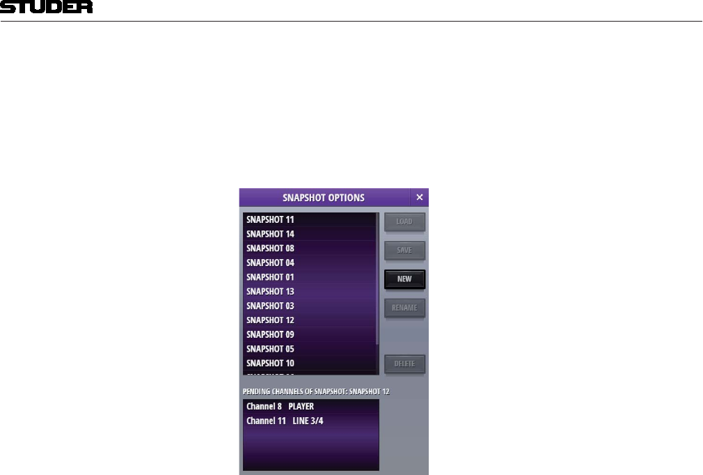
Micro Series
Micro Series 1-33
Document generated: 04.10.17 SW V1.2
ing channels.
channels
most recently loaded snapshot.
Note : After Pending Channels are not On-Master anymore, the User Snapshot
parameters are also applied to this channel - except for three parameters that
will NOT be applied. These parameters are :
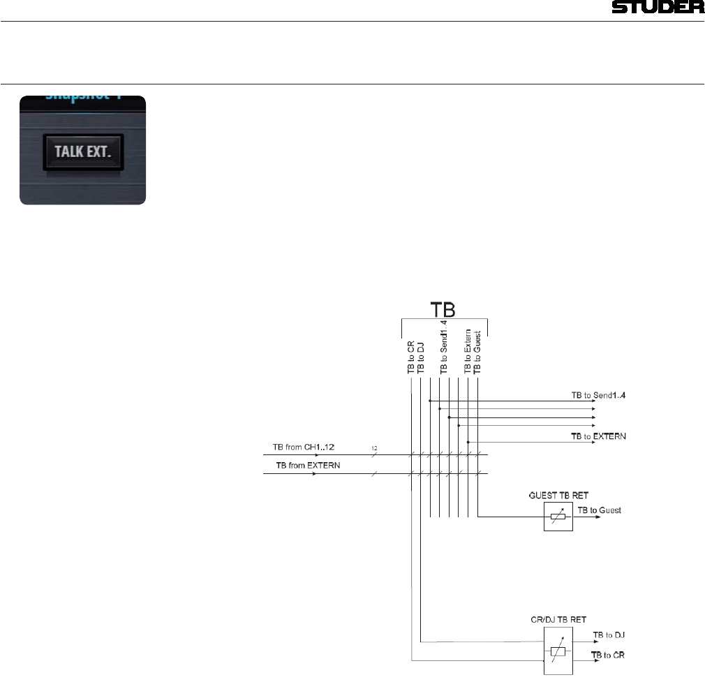
Micro Series
1-34 Micro Series Document generated: 04.10.17
SW V1.2
2.1.9.3 TB External
There is one TB target, called TB to Extern. This target can be assigned to
any of the physical output ports. This can be done in one of the Bus Config
pages. See chapter 2.3.2.
Please note that more than one output port can the target for TB to Extern.
One the other hand - there is exactly one External TB Input. This External
TB source can be configured in the CR Config page, under the tab Source,
TB from Extern. See chapter 2.3.3.
As an overview, here the TB blockdiagram is shown :
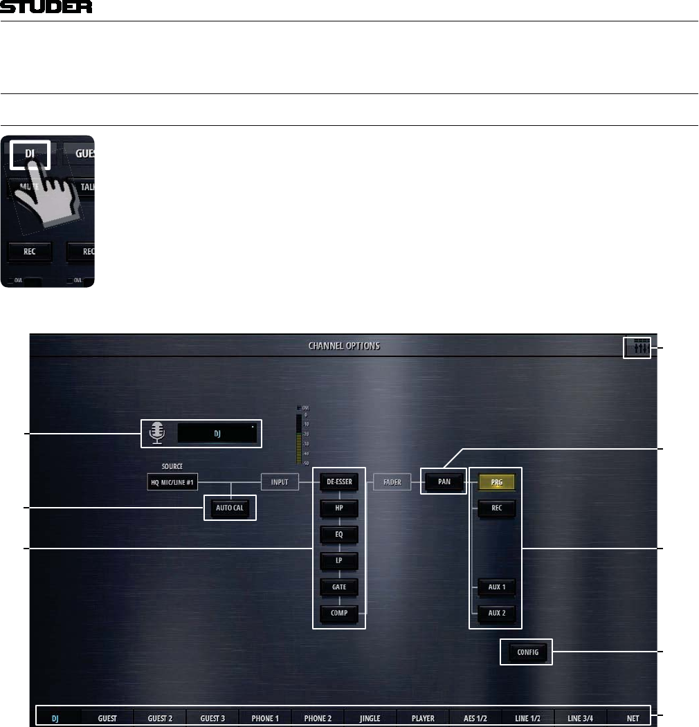
Micro Series
Micro Series 1-35
Document generated: 04.10.17 SW V1.2
2.2 L2 - The options level
2.2.1 Channel options
Channel options are entered by doubleclicking or touching the channel label
[] []
[]
[]
[]
[2]
[3]
[]
[1] Icon and Name Double-clicking on the name field allows the operator to enter a new channel
name. The icon is automatically chosen, depending on the channel role.
[2] Auto Cal Touching the AUTO CAL button starts the Automatic Gain Calibration
process. During the process the AUTO CAL button is flashing and the user
is able to see the calibration process on the channel meter. The calibration
process can be interrupted manually by touching the AUTO CAL button
again. During the calibration process, the input signal is analyzed and the
analogue input gain is adjusted automatically to reach the optimal mic/line
input level. The calibration is depending on the headroom setting in the meter
configuration section.
The Automatic Gain Calibration function is provided for all HQ Mic/Line
channels.
[3] Channel processing On/Off The channel processing On/Off buttons (DeEsser, HP, EQ, LP, Comp, Gate)
activate and deactivate the chosen processing block.
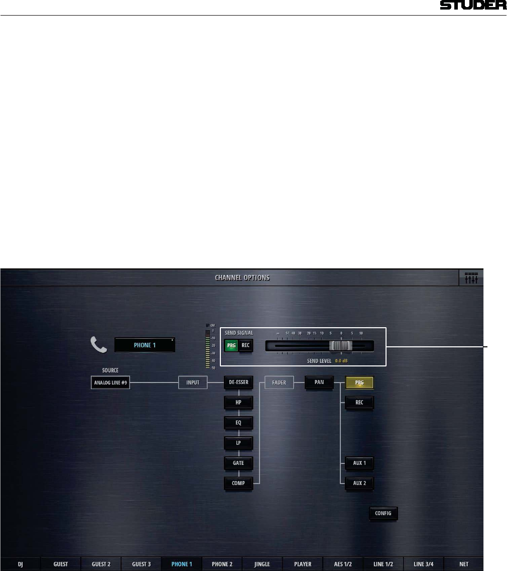
Micro Series
1-36 Micro Series Document generated: 04.10.17
SW V1.2
[4] Pan On/Off The Pan On/Off button activates and deactivates the panning section.
[5] Bus assign buttons These buttons assign the input channel to the desired busses.
[6] Config button Pressing this button opens the configuration page of the current channel.
There, the detailed channel configuration can be carried out, such as EQ
parameter setting, Dynamics parameter setting, etc..Details see chapter 2.3.
[7] Back to operation view Clicking or touching onto the area in the top right corner navigates back to
the operation view.
[8] Navigation Navigation to the option pages of other channels is provided on the bottom
channel navigation bar.
On channels of the role “Input for send”, there is an additional control element
:
1
[1] Send signal and Send level For “Input for send”- channels, on the channel options page also the bus for
the send signal, as well as its level can be chosen. “Input for send” - channels
are in other terms the N-1 bus owner channel. The send signal can then be
called the N-1 mix or the mix-minus signal.
The send level can also be set on the channel send view.
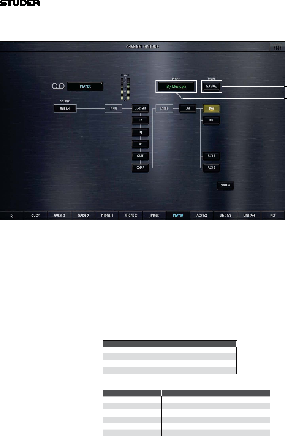
Micro Series
Micro Series 1-37
Document generated: 04.10.17 SW V1.2
On channels of the role “Player”, there are two additional control elements :
1
2
[1] Player Mode Automatic or Manual. This settings is the same as the mode setting in the
player view.
[2] Media Media and playlist selection
Clicking or touching onto the Media field, opens up the media dialog.
This list shows :
A playlist or an audio file can be selected.
The following externally created playlists are supported :
File Extension Description
.wpl Windows Media Player Playlist
.m3u Multimedia Playlist
.pla Winamp Playlist
.pls Text Based Multimedia Playlist
And the following audio fime formats are supported :
Format File E tension Description
Wave .wav uncompressed audio
AAC .aac lossy audio compression
MP3 .mp3 lossy audio compression
Ogg Vorbis .ogg lossy audio compression
AIFF .aif uncompressed audio
FLAC .flac lossless audio compression
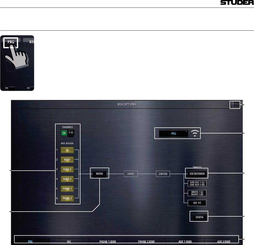
Micro Series
1-38 Micro Series Document generated: 04.10.17
SW V1.2
2.2.2 Bus options
Bus options are entered by doubleclicking or touching the send or bus label
when in send or bus view
1
2
[1] Bus assign Bus assign (for Sum and Aux busses) allows to assign all of the input chan-
nels to the currently viewed bus.
[2] Mono TheMono button mixes down the stereo signal to a mono signal and assigns
this signal to both, the Left and the Right leg of the stereo bus.
[3] Icon and Name Double-clicking on the name field allows the operator to enter a new bus
name. The icon is automatically chosen, depending on the bus type and bus
mode (Aux / N-1).
[4] USB Recorder Per default, the USB recorder is patched to the REC bus. If there is the need,
the USB recorder can be patched to any of the busses (Sum, N-1, Aux). There
is only one USB recorder available, which implies that it can only be patched
to one of the busses at the time.
[5] Config Config button. Pressing this button opens the configuration page of the current
bus. There, patching to outputs as well as chosing the bus mode and setting
the send levels can be done. Details see chapter 2.3.

Micro Series
Micro Series 1-39
Document generated: 04.10.17 SW V1.2
[7] Back to operation view Clicking or touching onto the area in the top right corner navigates back to
the operation view.
[8] Navigation Navigation to the option pages of other busses is provided on the bottom
channel navigation bar.
The options page of the N-1 busses differs only in the source selection:
1
2
[1] Source Send signal Prg or Rec (for N-1 busses)
The options page of the Aux busses has the same bus asign buttons as the
Sum busses.
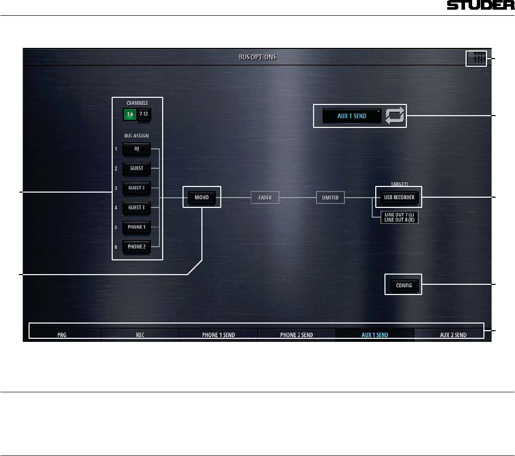
Micro Series
1-40 Micro Series Document generated: 04.10.17
SW V1.2
1
2
2.2.3 Meter options
Doubleclicking the label in the meter view also opens the channel options
2.2.4 Snapshot options
See chapter 2.1.9.2.
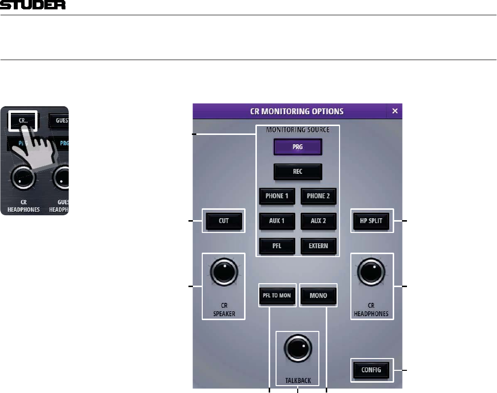
Micro Series
Micro Series 1-41
Document generated: 04.10.17 SW V1.2
2.2.5 CR Monitoring options
By clicking/touching the CR Monitoring Options button, the CR monitor-
ing panel is shown :
1
2
[1] CR monitoring source selector With these buttons the source for the control room monitoring is chosen. The
source is the same for the CR speakers and the CR headphones. The selected
source is displayed on the source displays
[2] Monitor Cut This button lets the operator manually cut the CR monitor.
[3] PFL to Mon With this option active, the current CR monitoring source gets replaced with
the PFL signal, as long as any PFL is active.
[4] Mono This button mixes the stereo CR source down to a mono signal for both, CR
speakers and CR headphones.
[5] Headphones Split Mode With this mode active, the PFL signal will be fed to the left channel of the
headphone, if PFL is active on any channel. On the right channel, still the pre-
viously selected CR source will be heard. Both signals are then downmixed
to mono.
Once PFL is released, the current CR source will be heard in stereo again.
If PFL is already selected as the CR source, actually pressing PFL on any
channel will not change the stereo PFL bus as the monitoring source.
[6] TB return level This rotary controls the incoming TB signal level which is fed to the CR
speakers as well as to the CR headphones. Please note that the current CR
source signal is then dimmed by 20dB.
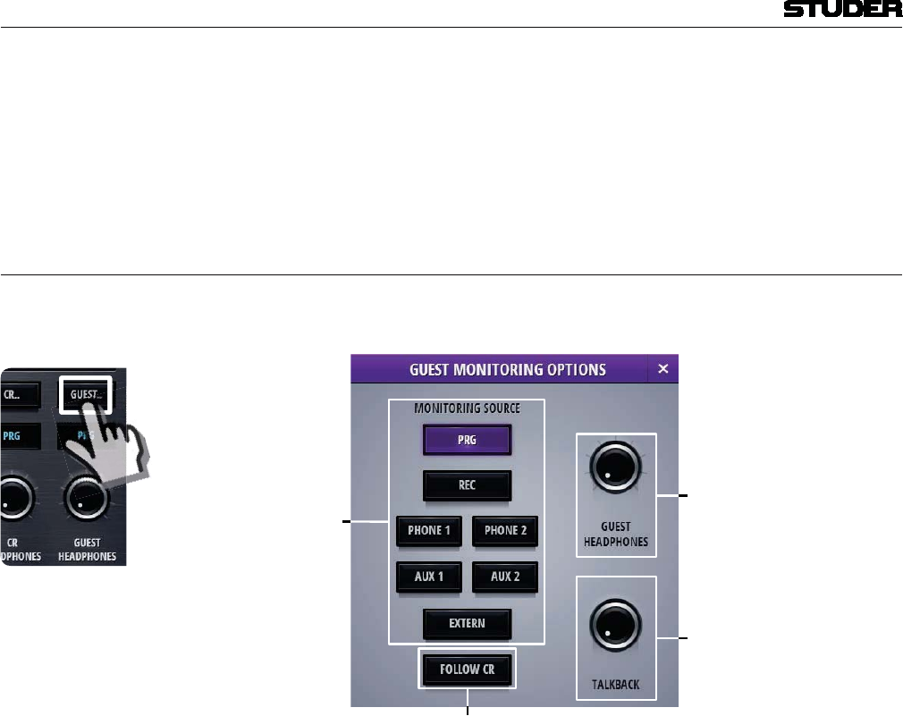
Micro Series
1-42 Micro Series Document generated: 04.10.17
SW V1.2
[7] CR speaker level This rotary controls the level of the CR speakers.
[8] CR headphones level This rotary controls the level of the CR headphones.
[9] Config button This button navigates to the CR monitoring config page.
2.2.6 Guest Monitoring options
By clicking/touching the Guest Monitoring Options button, the guest
monitoring panel is shown :
[] [3]
[2]
[]
[1] Monitoring source selector With these buttons the source for the guest monitoring is chosen. The selected
source is displayed on the source display.
[2] Follow CR This button selects the same source as currently active on the CR monitoring
section.
[3] Guest headphones level This rotary controls the level of the Guest headphones.
[4] TB return level This rotary controls the incoming TB signal level which is fed to the Guest
headphones. Please note that the current Guest monitoring source signal is
then dimmed by 20dB.
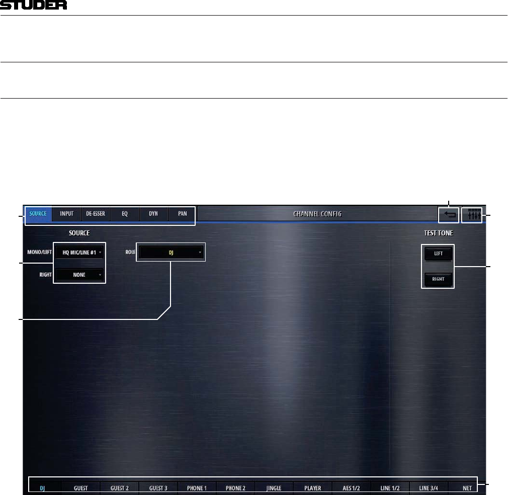
Micro Series
Micro Series 1-43
Document generated: 04.10.17 SW V1.2
2.3 L3 - The configuration level
2.3.1 Channel config
Clicking/touching the Config button in the channel options view allows
access to the channel config page. Six processing block selection tabs navi-
gate to a channels different processing sections.
The config page of the channels source section holds control elements nece-
sarry to set the channels source selection.
1
2
[1] Processing tabs These tabs lets the operator navigate to the desired processing block of a
channel.
[2] Source selection With these two pull-down menues, the source for the left channel leg, and
the source for the right channel leg can be selected. If for the right channel
leg the selection remains on “None”, then the channel is a mono channel. An
exception are the sources “USB” and “AES” - these sources are always stereo
sources and are only selected on the first pull-down menu.
[3] Channel role Here the role of the channel is defined. The choice is as follows :
Default - for a simple input channel, no special behaviour
DJ - for a mic source located in the control room (CR)
Guest - for a mic source located in the control room (CR)
Input for send 1 - the bus owner of a N-1 bus
Input for send 2 - the bus owner of a N-1 bus
Input for send 3 - the bus owner of a N-1 bus
Input for send 4 - the bus owner of a N-1 bus

Micro Series
1-44 Micro Series Document generated: 04.10.17
SW V1.2
Jingle
Track
Depending on the channel role, the channels control elements on the GUI are
different.
[4] Test tone With these two buttons. test tone can be fed to the left and the right leg of the
channel. The test tone signal is defined in the “Settings”-page
[5] Navigation back. Clicking or touching onto this area navigates back to the Options page of this
channel.
[6] Back to operation view Clicking or touching onto the area in the top right corner navigates back to
the operation view.
[7] Navigation to other channels Navigation to the config pages of other channels is provided on the bottom
channel navigation bar.
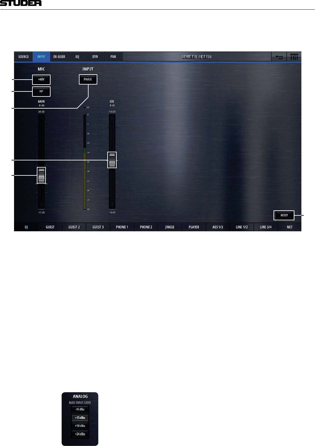
Micro Series
Micro Series 1-45
Document generated: 04.10.17 SW V1.2
The config page of the channels input section holds control elements necesarry
to set the channels input levels :
1
2
If the channels source selection is a Mic source, then these three elements are
provided on the left side of the page.
[1] 48V Switches phantom power (48V) to the microphone on and off.
[2] Highpass filter Activates a highpass filter on the analog side of the microphone input, before
theA/D converter. This can be useful to filter out rumbling noise on speach
signals. The cutoff frequency of this filter is fixed at 75Hz and it has a slope
of 12dB/oct.
[3] Mic gain This fader sets the microphone gain.The gain range is 86dB and the absolute
numbers on the fader-scale are depending on the Max Level of the analog
I/O. Max Level is defined in the Settings page.
On channels with Line inputs as source, other control elements are displayed
in place of the Mic control elements.
Max Level The Max Level setting defines the systems reference line level for 0dBFS.
This is a global setting found on the Settings-page. But it can also be set on
a channel by channel basis. This setting needs to correspond with the actual
level calibration of the analogue input- and output interfaces. As a standard,
the Micro Core is shipped with all analogue levels calibrated to +9dBu. This
means that the highest possible analog signal that leaves the mixer is +9dBu.
And it also means, that signals which are higher than +9dBu will clip the A/D
converters.
Then, in the second section of this page, the control elements of the digital
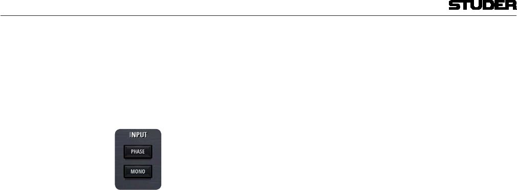
Micro Series
1-46 Micro Series Document generated: 04.10.17
SW V1.2
processing are found.
[4] Phase Inverts the mono signal or the left channel of the stereo signal if turned On.
[5] Input calibration This fader allows the operator to trim the signal by +/-18dB
On stereo channels, in this section also a Mono button can be found. This
button downmixes the stereo signal to mono : Mono=(Left+Right)-3dB
[6] Reset This button sets all values of this processing block to the default values. Please
note that this button can be found on every tab of the channel config page.
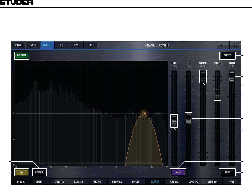
Micro Series
Micro Series 1-47
Document generated: 04.10.17 SW V1.2
The config page of the channels de-esser section holds control elements
necesarry to set the channels De-esser parameters :
1
1
2
11
[1] DeEsser On/Off Activates the De-Esser when illuminated.
[2] RTA A real time frequency analysis of the channels signal is computed and dis-
played in the spectrum field of the De-Esser. This is a visual aid helping the
operator to find the problematic areas of the channels signal.
[3] Reverse The reverse function allows listening to the part of the signal which is going
to be removed by the De-Esser.
[4] Freq Sets the operation frequency of the De-Esser.
[5] QSets the width of the bandpass filter.
[6] Threshold Sets the threshold of the bandpass compressor.
[7] Ratio Sets the ratio of the bandpass compressor.
[8] Attenuation Controls the amount of gain reduction. Attenuation is only available when
Auto is active.
[9] Auto Enables automatic threshold, which dynamically adjusts the De-Esser thresh-
old according to the incomming audio. When Auto is active, Ratio and
Threshold controls are disabled in place of Attenuation.
[10] Reset This button sets all values of this processing block to the default values.
[11] Presets Opens the preset window for the De-Esser presets.
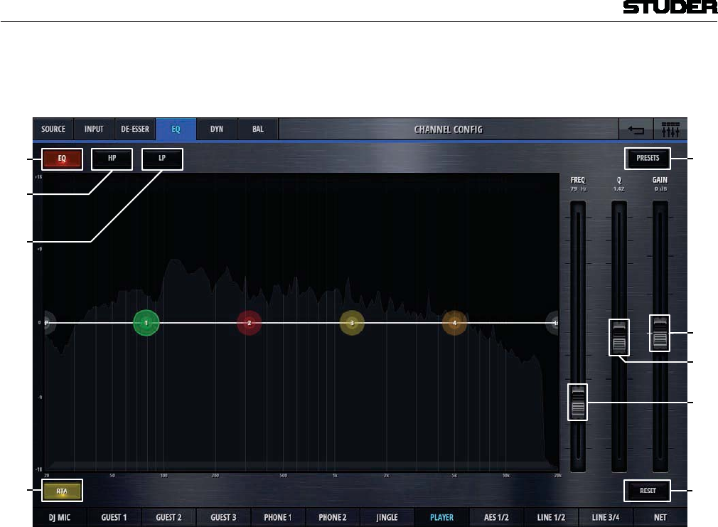
Micro Series
1-48 Micro Series Document generated: 04.10.17
SW V1.2
The config page of the channels eq section holds control elements necesarry
to set the channels eq and high- and lowpassfilter :
1
2
[1] EQ On/Off Activates the EQ when illumnated.
[2] Highpass filter On/Off Activates and deactivates the highpass filter.
[3] Lowpass filter On/Off Activates and deactivates the lowpass filter.
[4] RTA A real time frequency analysis of the channels signal is computed and dis-
played in the spectrum field of the EQ. This is a visual aid helping the operator
to find the problematic areas of the channels signal.
[5] Freq Controls the frequency parameter of the selected EQ band. One of the four
EQ bands can easily be selected by clicking or touching onto the numbered
(1-4), coloured circles on the frequency axis.
[6] QSets the width of the EQ band.
[7] Gain Sets the gain (+/- 18dB) of the EQ band.
[8] Reset This button sets all values of this processing block to the default values.
[9] Presets Opens the presets window for EQ presets.
The EQ can also completely be operated on the spectrum field - either by
using mouse or touchscreen.

Micro Series
Micro Series 1-49
Document generated: 04.10.17 SW V1.2
If either highpass- or lowpass circles are selected, the filter parameters are
displayed instead of the EQ band parameters.
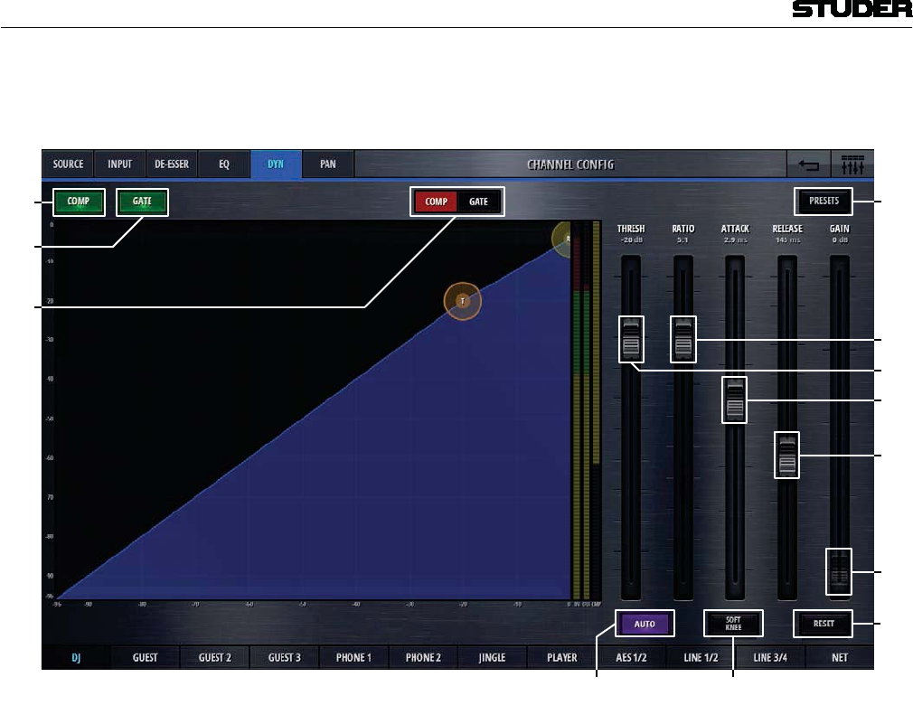
Micro Series
1-50 Micro Series Document generated: 04.10.17
SW V1.2
The config page of the channels dynamics section holds control elements
necesarry to set the channels compressor and gate parameters :
[]
[]
[2]
[]
[2]
[3] []
[]
[]
[]
[] [0]
[1] Comp On/Off Activates the compressor when illuminated.
[2] Gate On/Off Activates the gate when illuminated.
[3] Comp/Gate Selects either the Comp- or the Gate view.
[4] Threshold Sets the threshold parameter of the compressor. The lower the threshold, the
more signal compression is achieved.
[5] Ratio Sets the compression ratio parameter. A ratio of 1:1 doesn’t process the signal
at all, a ratio of 3:1 is a medium compression, 5:1 a heavy compression and
settings above 10:1 are called limiting.
[6] Attack time Sets the attack time of the compressor. The shorter this attack time is, the
quicker a gain reduction is applied to the signal.
[7] Release time Sets the release time of the compressor. The longer this release time is, the
longer it takes until the gain reduction is released and the signal becomes
unprocessed again.
[8] Gain Sets the makeup gain of the compressor. This is a simply signal amplification
stage that allows to bring the processed signal back to the desired level.
[9] Auto This button overrules the Gain parameter and automatically applies as much
makeup gain as needed to make the processed output signal as loud as the
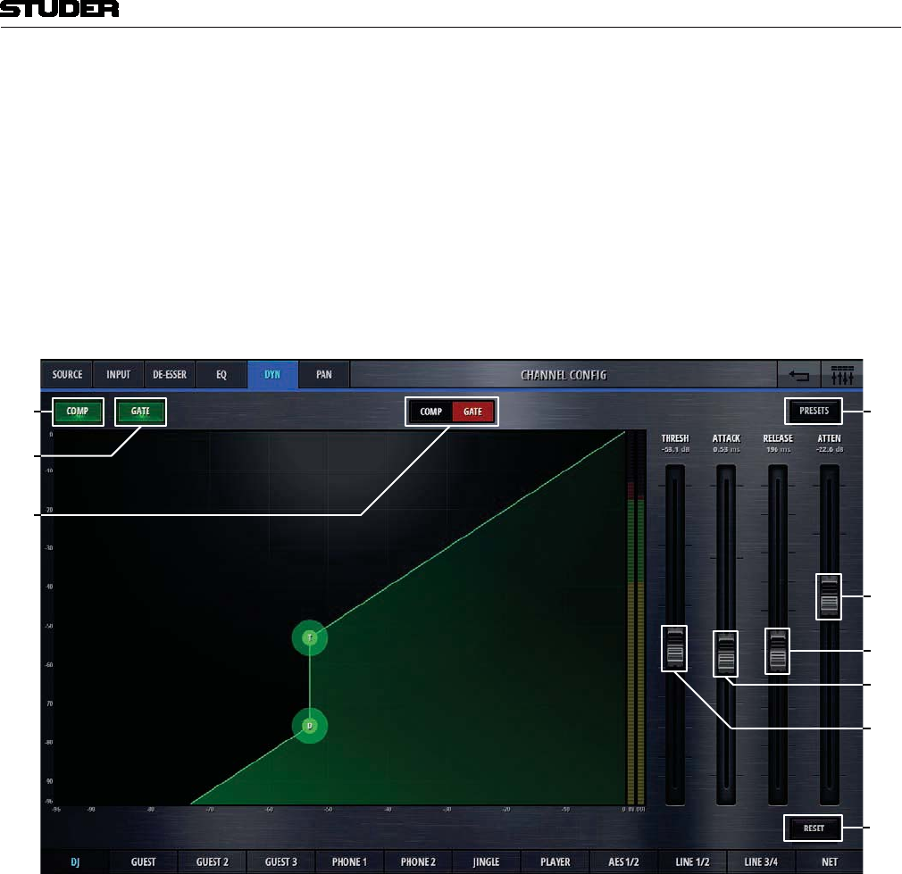
Micro Series
Micro Series 1-51
Document generated: 04.10.17 SW V1.2
unprocessed input signal.
[10] Softknee Sets the Softknee mode On and Off. The activated Softknee mode softens the
transition area around the threshold value.
[11] Reset This button sets all values of this processing block to the default values.
[12] Presets Opens the presets window for Compressor presets
Here, the gate view is shown :
1
2
[1] Comp On/Off Activates the compressor when illuminated.
[2] Gate On/Off Activates the gate when illuminated.
[3] Comp/Gate Selects either the Comp- or the Gate view.
[4] Threshold Sets the threshold parameter of the gate. With a low threshold, the noise gate
will open up already for very small signals. With a higher threshold, only
larger signals will trigger the noise gate to open up.
[5] Attack time Sets the attack time of the gate. The shorter this attack time is, the quicker
the noise gate opens up.
[6] Release time Sets the release time of the gate. The longer this release time is, the longer it
takes until the noise gate is closed again.
[7] Attenuation Sets the attenuation parameter of the gate. To make the noise gate completely

Micro Series
1-52 Micro Series Document generated: 04.10.17
SW V1.2
blocking a signal, the attenuation must be a large value. If the attenuation is
left at 0dB, the noise gate has no influence at all.
[8] Reset This button sets all values of this processing block to the default values.
[9] Presets Opens the presets window for Gate presets
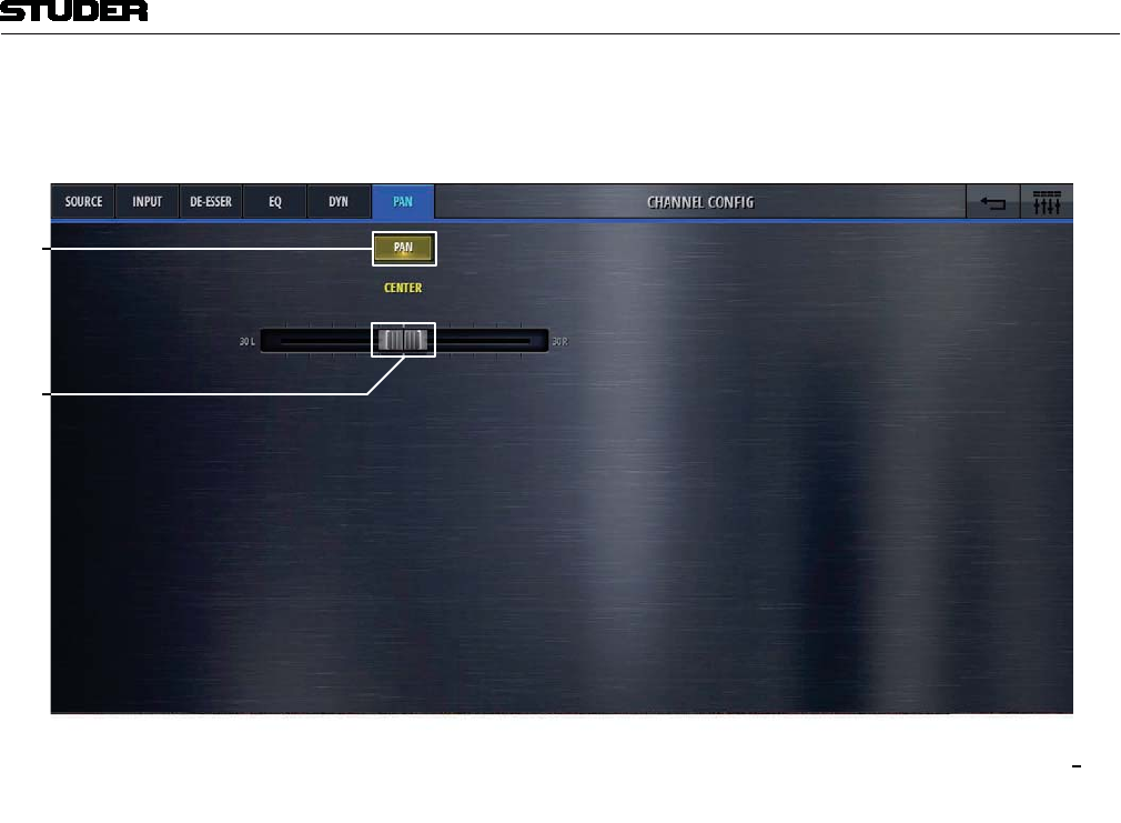
Micro Series
Micro Series 1-53
Document generated: 04.10.17 SW V1.2
The config page of the channels pan section holds control elements necesarry
to set the channels panning/balance :
1
2
Pan/Bal depending wether mono or stereo channels
[1] Pan/Bal On/Off Activates the panner when illuminated.
[2] Pan/Bal Positions the signal between the left and the right leg of all stereo busses it
is assigned to.
[3] Reset This button sets all values of this processing block to the default values.
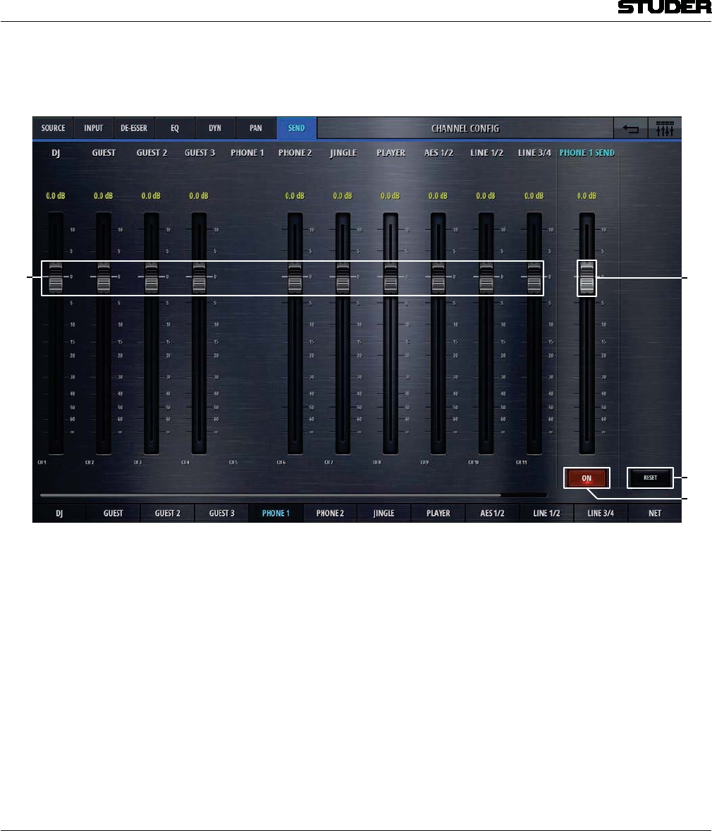
Micro Series
1-54 Micro Series Document generated: 04.10.17
SW V1.2
The config page of the channels send section holds control elements necesarry
to set the channels send levels :
12
[1] Send levels These are the send levels of all input channels. Since the input channels are
fed “post-fader” to the send bus, these send levels can be regarded as a trim
function. Please note that the channel that we are currently configuring cannot
be sent to its own send bus (N-1 concept, also called mix-minus) .
[2] Master Send level Sets the output level of the send bus.
[3] On/Off Switches the output signal of the send bus on and off.
[4] Reset Resets all parameters.
2.3.2 Bus Config
Clicking/touching the Config button in the bus options view allows access
to the bus config page.
Two or three selection tabs navigate to the different sections. PRG and REC
busses have the tabs Targets and Outputs. All other busses have
Send, Targets and Outputs tabs.
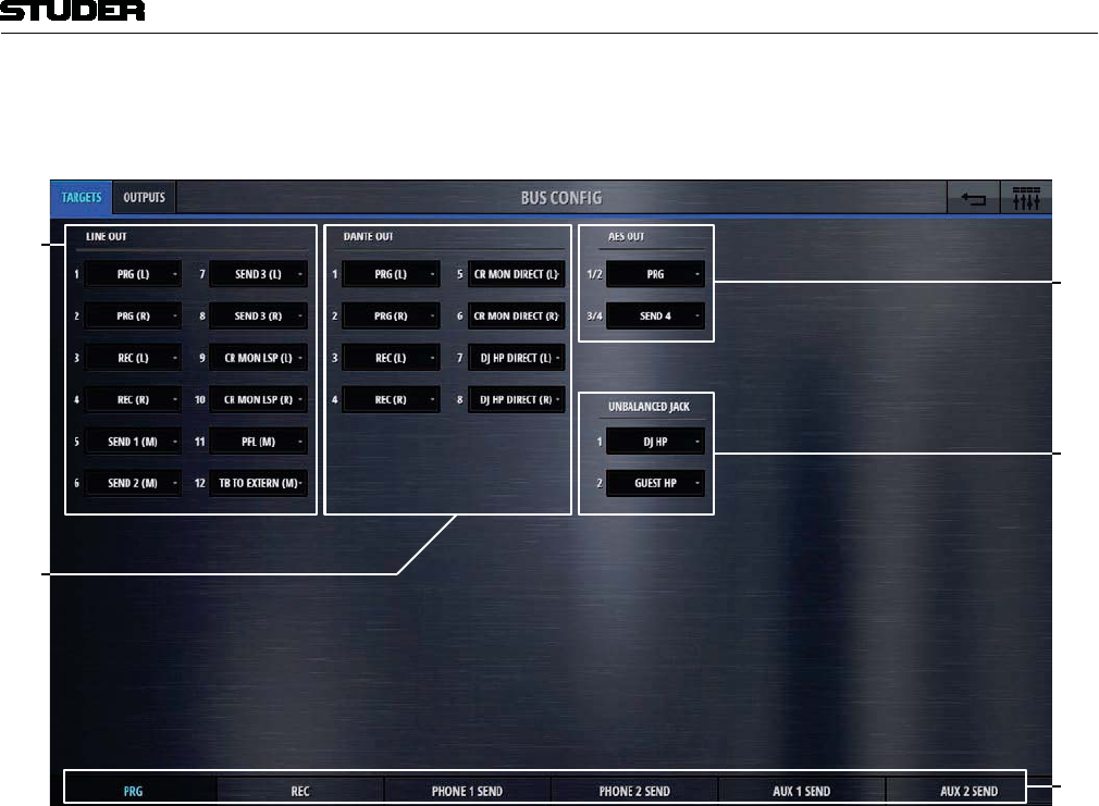
Micro Series
Micro Series 1-55
Document generated: 04.10.17 SW V1.2
The config page of the busses Target section holds control elements necesarry
to assign mixer internal sources to the output ports.
1
2
[1] Line Out Here, the sources for the 12 Line Out output ports can be assigned. This is
done by clicking/touching on the source. A choice of all possible sources
appears in a list where simply the desired source can be selected. There are
sources that are marked (L) or (R) or (M). As Line Out ports are mono, only
mono sources can be selected, (L) stands for the left leg of a stereo source,
(R) stands for the right leg of a stereo source, and (M) is the stereo source
downmixed to mono.
[2] Dante Out Here, the sources for the eight Dante Out output ports can be assigned.
[3] AES Out Here, the sources for the two stereo AES Out output ports can be assigned.
[4] Unbalanced Jack Here, the sources for the two stereo headphone output ports can be assigned.
[5] Navigation to other busses Navigation to the config pages of other busses is provided on the bottom bus
navigation bar.
Note : Please note, that this view is the same for all six busses !
The output assignment can only be made once for each output port.
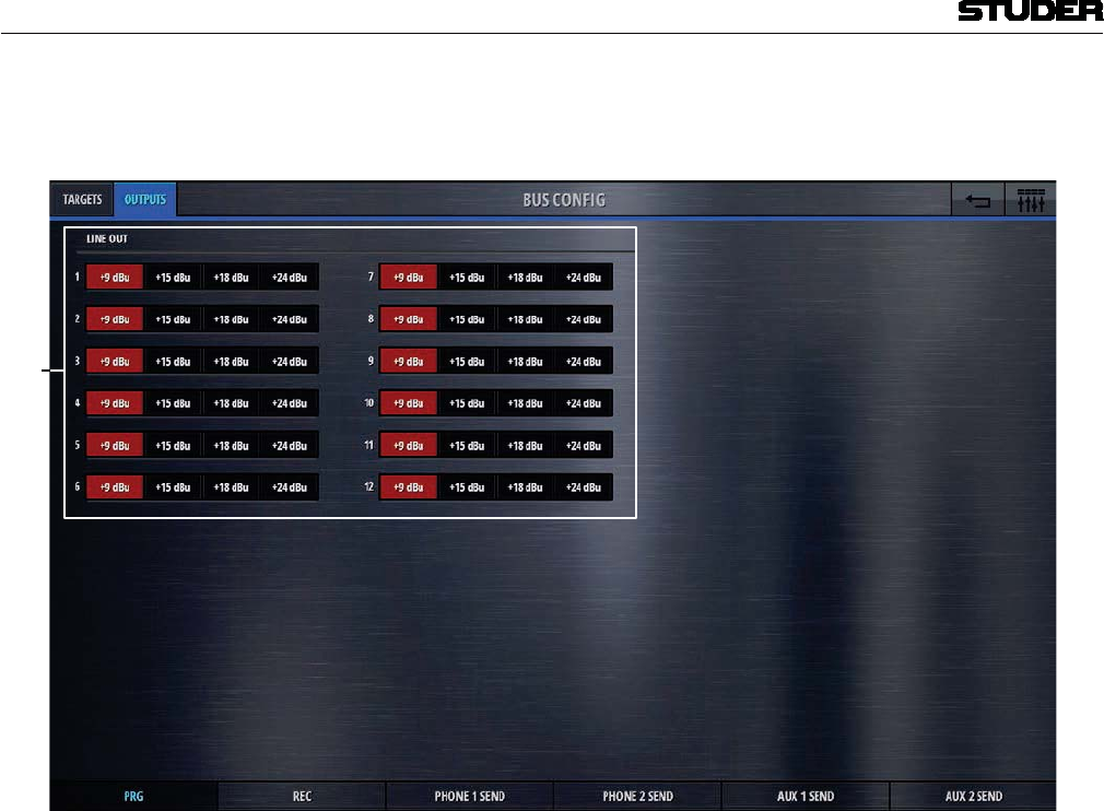
Micro Series
1-56 Micro Series Document generated: 04.10.17
SW V1.2
The config page of the busses Output section holds control elements necesarry
to calibrate the levels of the analog output ports.
1
[1] Line Out Here, the Max Level of the 12 Line Out output ports can be selected. This
setting defines the analog signal level for the highest possible internal signal
of 0dBFS. It can set for each Line Out individually.
Note : Please note, that this view is the same for all six busses !
On the Settings page under the tab Audio, this setting can be made globally
for all analog input- and output ports at once.
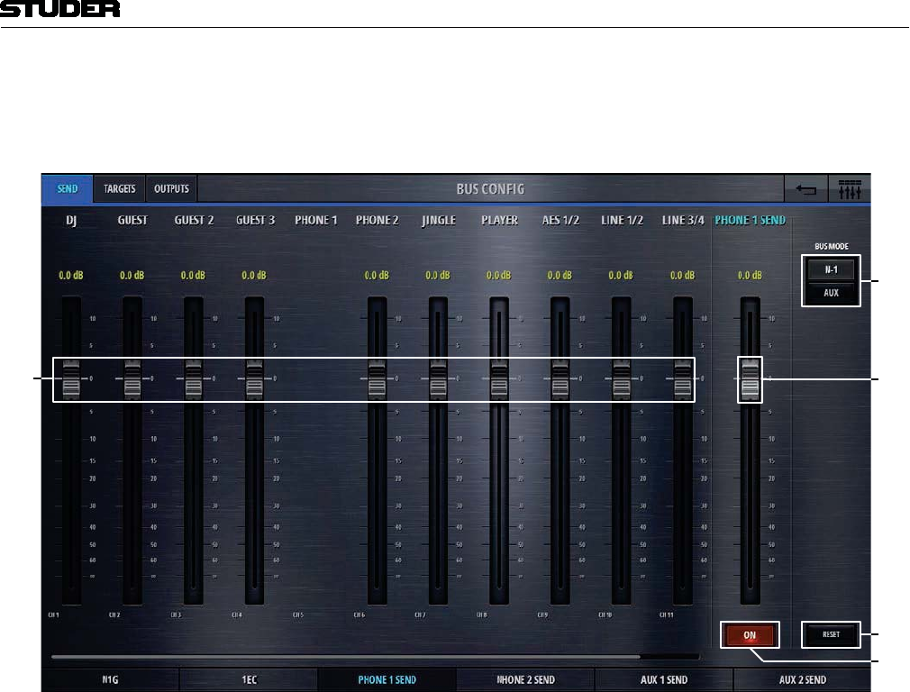
Micro Series
Micro Series 1-57
Document generated: 04.10.17 SW V1.2
The config page of the N-1 busses Send section holds control elements
necesarry to set the actual send levels of contributing channels - e.g. to set
the mix.
[]
[]
[2]
[3]
[]
[1] Send levels These are the send levels of all input channels to the currrently chosen bus.
Please note that the channel that we are currently configuring cannot be sent
to its own send bus (N-1 concept, also called mix-minus) .
[2] Master Send level Sets the output level of the send bus.
[3] On/Off Switches the output signal of the send bus on and off.
[4] Bus Mode Lets the user select the bus mode that can either be N-1 or Aux.
N-1 : this mode is made for busses that are feeding a return signal to remote
positions. This mode doesn’t allow the input signal of the remote source
to be assigned to the bus. With this bus mode, the remote source (e.g. a
reporter) will never have his own signal in his return feed. This is opti-
mal to prevent echo’s that could be introduced through long distance
signal transmission.
Aux : this is the bus mode that allows all sources to be assigned to the
bus . The user can decide whether the signal should be sent to the bus
eitherbefore or after the channals fader. This can be set for each source
individually by chosing Pre or Post with the button on the top. Also
each source has an individual on/off button to select the desired bus
assign (see image below).
[5] Reset Resets all parameters.
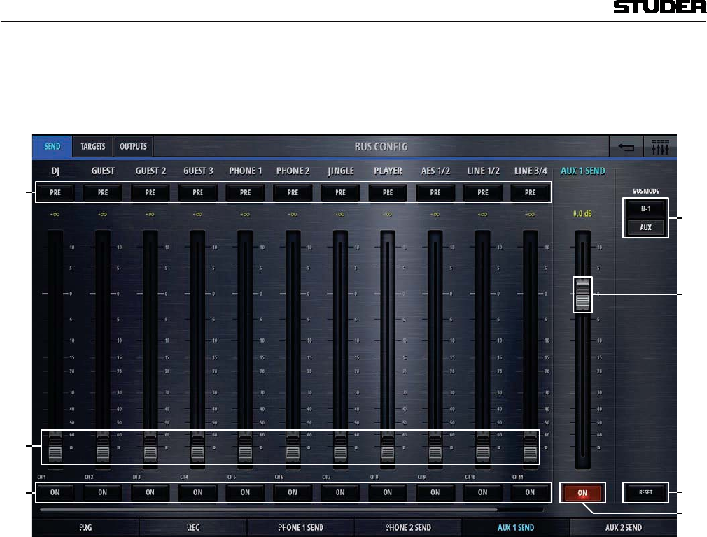
Micro Series
1-58 Micro Series Document generated: 04.10.17
SW V1.2
The config page of the AUX busses Send section holds control elements
necesarry to set the actual send levels of contributing channels - e.g. to set
the mix.
2
1
[1] Pre/Post Lets the user decide whether the signal should be sent to the Aux bus either
before or after the channals fader. “Pre” stands for before the fader, “Post”
stands for after the fader.
[2] Send levels These are the send levels of all input channels to the currrently chosen bus.
[3] Send On/Off Each source has an individual On/Off button to assign the channel to the Aux
bus.
[5] Master Send level Sets the output level of the send bus.
[4] On/Off Switches the output signal of the send bus on and off.
[6] Bus Mode Lets the user select the bus mode that can either be N-1 or Aux.
N-1 : this mode is made for busses that are feeding a return signal to remote
positions. This mode doesn’t allow the input signal of the remote source
to be assigned to the bus. With this bus mode, the remote source (e.g. a
reporter) will never have his own signal in his return feed. This is opti-
mal to prevent echo’s that could be introduced through long distance
signal transmission.
Aux : this is the bus mode that allows all sources to be assigned to the
bus . The user can decide whether the signal should be sent to the bus
eitherbefore or after the channals fader. This can be set for each source
individually by chosing Pre or Post with the button on the top. Also each
source has an individual on/off button to select the desired bus assign.
[7] Reset Resets all parameters.
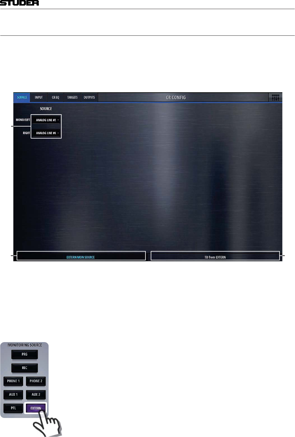
Micro Series
Micro Series 1-59
Document generated: 04.10.17 SW V1.2
2.3.3 CR Monitoring Config
Clicking/touching the Config button in the CR Monitoring options view
allows access to the CR config page. Five selection tabs navigate to the dif-
ferent sections.
The config page of the Source section holds control elements necesarry to
selecte a source for two different purposes.
1
2
[1] Source Here, a mono or stereo source can be chosen for two different purposes :
External Monitoring Source
TB from Extern
Depending on the selected tab :
[2] External Monitoring Source The signal that is selected here becomes the external monitoring source. It
will be active on the CR monitor when the corresponding button is pressed.

Micro Series
1-60 Micro Series Document generated: 04.10.17
SW V1.2
[3] TB from Extern Allows to define the input port, where the external TB returns into the Micro
Core. This is the return signal of the external TB circuit. The send signal (TB
to Extern) can be defined in the Target tab.
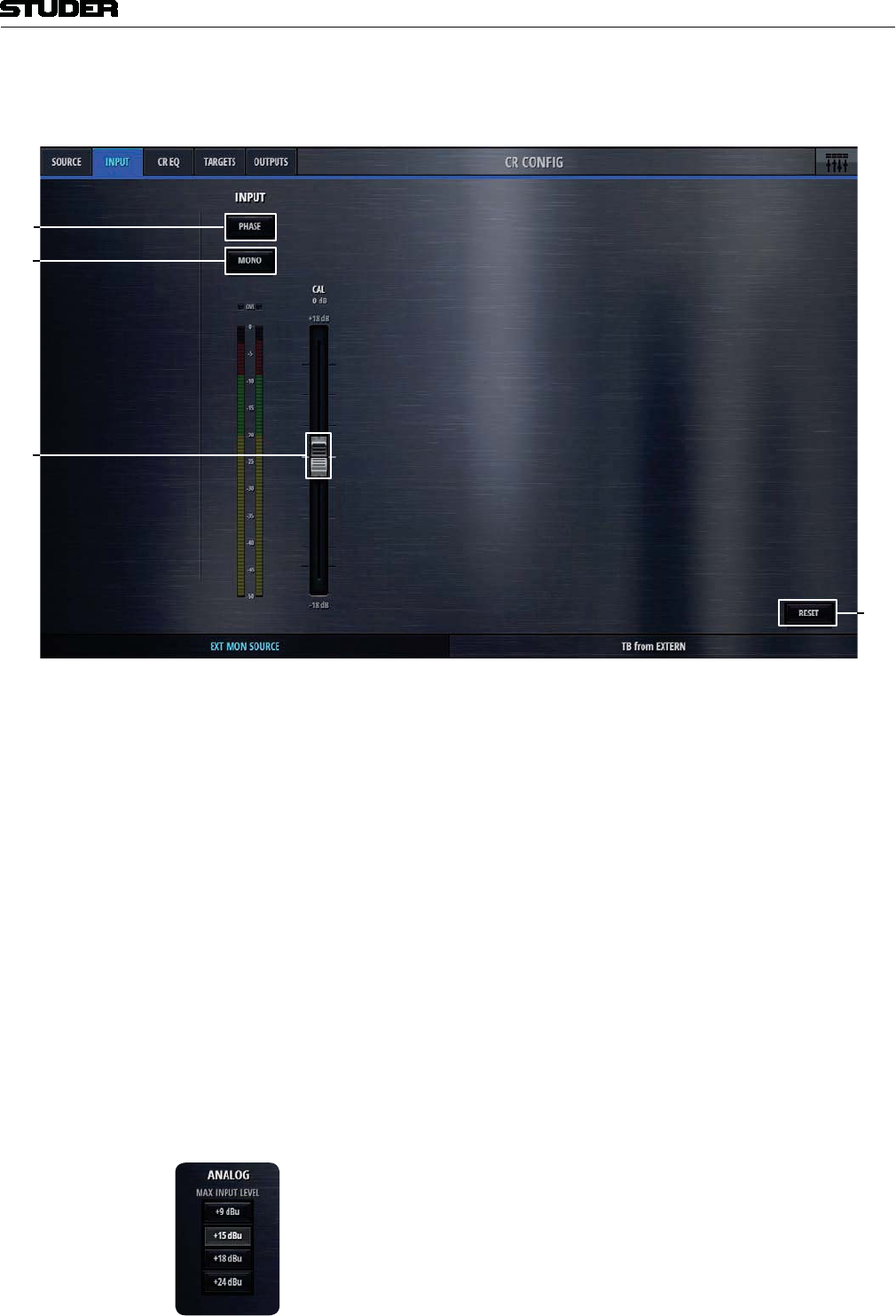
Micro Series
Micro Series 1-61
Document generated: 04.10.17 SW V1.2
On the Input tab of the CR Config page, the input parameters of the two
selected source-signals can be set.
1
2
[1] Phase If the selected source signal is a stereo signal, the Phase button is available.
This button inverts the phase of the left chanel.
[2] Mono Also for stereo sources - the Mono button mixes down the stereo signal to a
mono signal.
[3] Input Calibration The Cal fader allows to calibrate the signal within a range of +/- 18dB.
[4] Reset This button sets all values of this processing block to the default values.
If the channels source selection is a Mic source, then three more elements are
provided on the left side of the page. These are :
48V
Highpass Filter
Mic Gain
On channels with Line inputs as source, other control elements are displayed
in place of the Mic control elements.
Max Level The Max Level setting defines the systems reference line level for 0dBFS.
This is a global setting found on the Settings-page. But it can also be set on
a channel by channel basis. This setting needs to correspond with the actual
level calibration of the analogue input- and output interfaces. As a standard,
the Micro Core is shipped with all analogue levels calibrated to +9dBu. This
means that the highest possible analog signal that leaves the mixer is +9dBu.
And it also means, that signals which are higher than +9dBu will clip the A/D
converters.
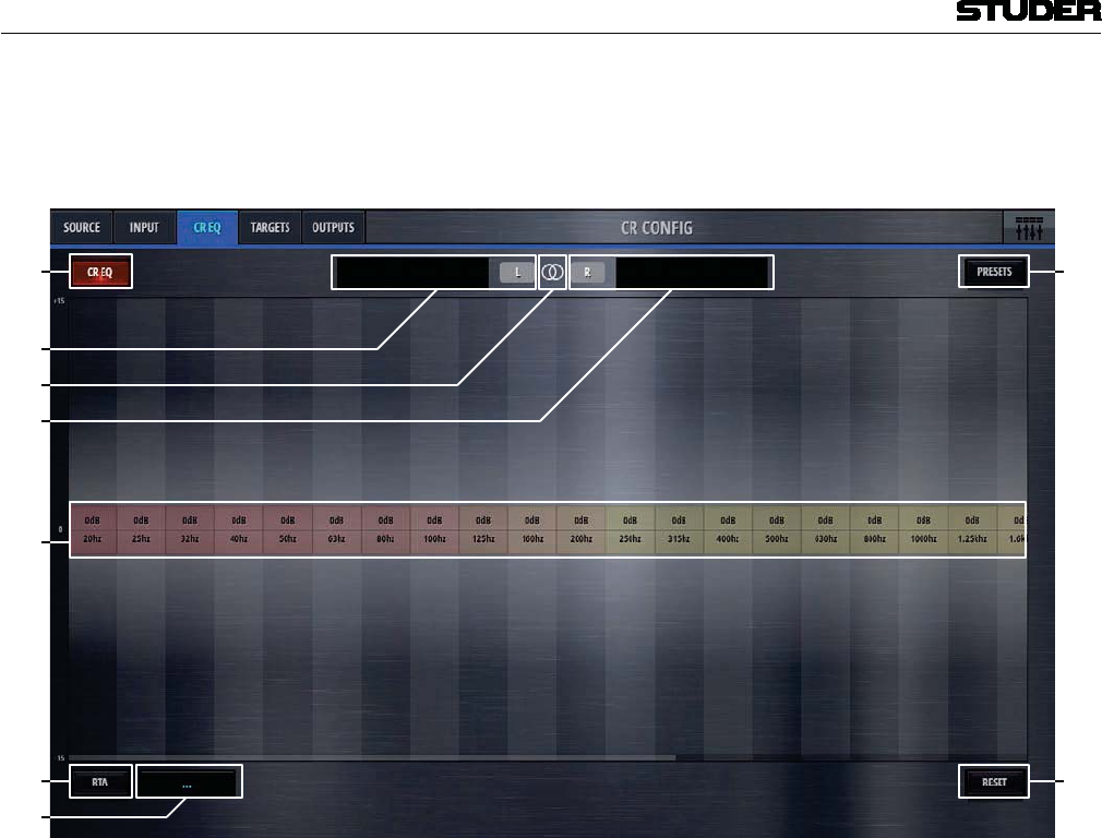
Micro Series
1-62 Micro Series Document generated: 04.10.17
SW V1.2
The CR EQ tab displays a graphic equalizer (GEQ) that is inserted into the CR
MON LSP signal path. It can be used to flatten undesired room resonances
of the control room.
1
[2]
[]
[]
[3]
[]
[]
[1] CR EQ Activates the GEQ when illuminated.
[2] Left side This area displays an overview icon of the left side portion of the GEQ. Click-
ing/touching onto this area allows to operate the 32 bands of the GEQ in the
large window below.
[3] Link/Unlink Clicking/touching onto this area unlinks the left- and the right side of the
GEQ. As a default, the left and right side are linked, allowing to control either
side of the GEQ while the parameters of the other side automatically are set
to the same values.
Please note that when linking both sides, always the current setting of the left
side GEQ is taken and applied to both sides.
[4] Right side This area displays an overview icon of the right side portion of the GEQ.
Clicking/touching onto this area allows to operate the 32 bands of the GEQ
in the large window below.
[5] GEQ bands These are the actual GEQ bands that can be used to set the desired band values
in a range of +/- 15dB. Clicking/touching and dragging at the same time slides
the bands up or down.
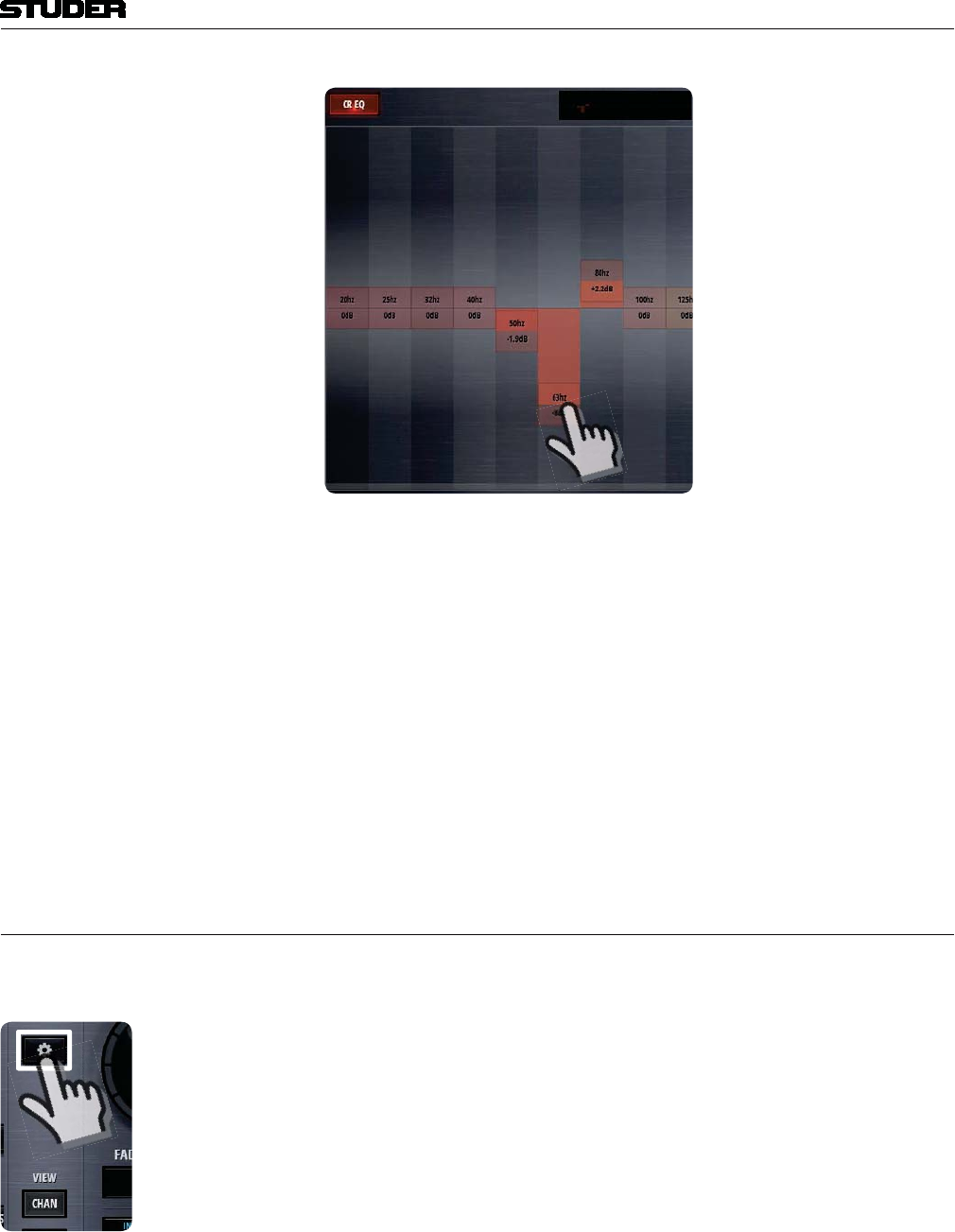
Micro Series
Micro Series 1-63
Document generated: 04.10.17 SW V1.2
[6] RTA A real time frequency analysis of a selectable signal is computed and displayed
in the spectrum field of the GEQ. This is a visual aid helping the operator to
find the problematic areas of a specific source.
[7] RTA Source This is the source selector for the signal that is fed into the RTA.
[8] Presets Opens the presets window for GEQ presets.
.
[9] Reset This button flattens and deactivates the GEQ.
The Targets- and Outputs tabs are the same pages as also shown in the bus
config pages.
2.4 Settings view
A click or touch onto the Settings button leads to the Settings page where
the basic configuration of the Micro Core is made.
On the Network tab, the network configuration can be made and the current
status of the network is displayed.
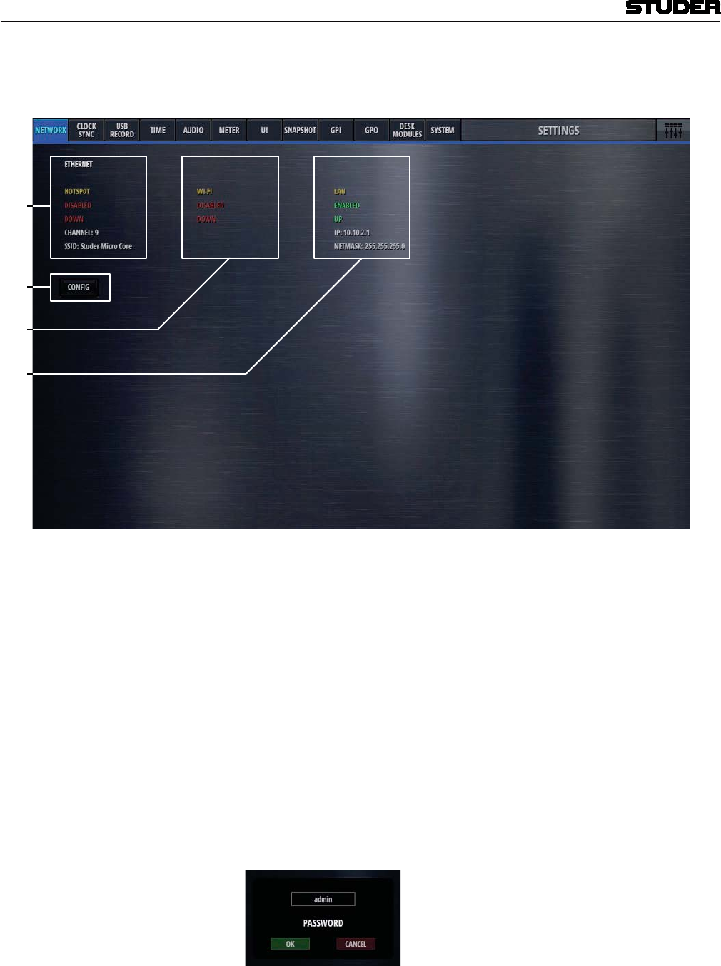
Micro Series
1-64 Micro Series Document generated: 04.10.17
SW V1.2
On the Network tab, the network states are shown and the network can be
configured.
1
2
[1] Hotspot status display Here the current status of the internal Hotspot is shown.
The base unit of the OnAir Micro is able to produce its own WLAN, or with
other words, it has its own Wireless Access Point (WAP).
When the Hotspot is enabled, the Wi-Fi is automatically disabled and vice
versa.
[2] Wi-Fi status display This section shows the current state of the Wi-Fi section. When the Wi-Fi is
enabled, the Hotspot is automatically disabled and vice versa.
[3] Ethernet status display Here the current settings of the wired Ethernet port are shown. The Ethernet
port can be used while Hotspot/Wi-Fi access is also active.
[4] Config button By pressing this button, the network configuration pages are opened.
The Config logon window appears, and the following password need to be
entered :
Password : admin
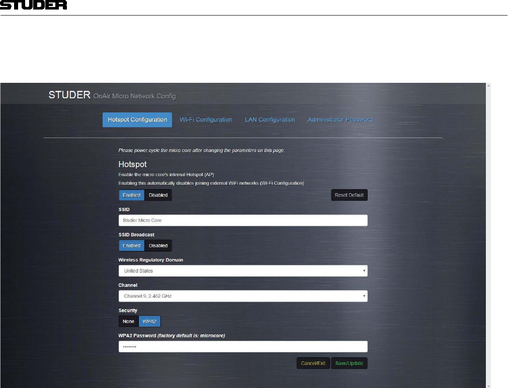
Micro Series
Micro Series 1-65
Document generated: 04.10.17 SW V1.2
Hotspot Configuration Page
Hotspot Enable/Disable This page allows to enable or disable the internal Hotspot.
Wireless Frequency The hotspot can use two different frequency ranges : 2.4GHz or 5GHz
SSID Service Set Identifier . This is the name of the WLAN, as it appears on any
device receiving this WLAN if SSID Broadcast is enabled..
SSID Broadcast When enabled, the name of the WLAN (SSID) will be visible for all devices
that can receive it. If disabled, the WLAN name will be hidden - while the
WLAN is still usable for the ones that know the name.
Wireless Regulatory Domain Countries apply their own regulations to the allowable channels. This pull-
down selects the country where you are using the Micro Core.
Channel Here, the WLAN channel can be chosen. A number of channels are available
within the Wi-Fi spectrum, depending on the Regulatory Domain - 13 for
Europe (ETSI), and 11 for North America (FCC), for example. Third-party
software is available to help select Wi-Fi channels.
Security Allows to make use of a password protection for the WLAN.
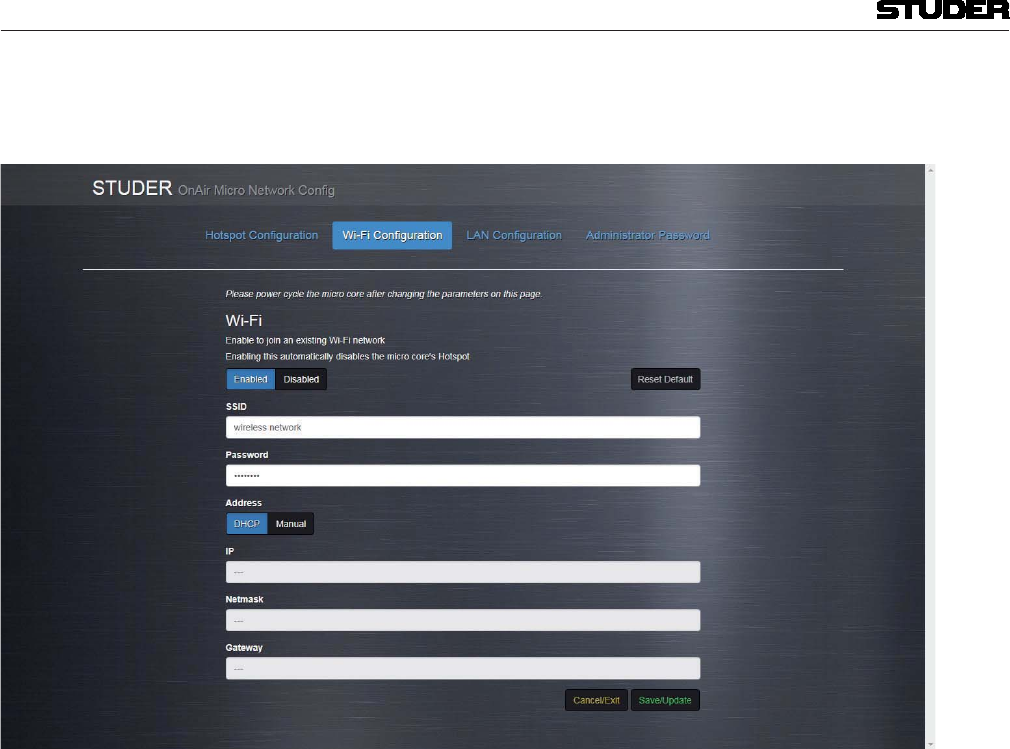
Micro Series
1-66 Micro Series Document generated: 04.10.17
SW V1.2
Wi-Fi Configuration Page
Enable/Disable This page allows to enable or disable the Wi-Fi network. When the Wi-Fi is
enabled, the Hotspot is automatically disabled and vice versa.
Wireless Frequency The Wi-Fi network can use two different frequency ranges : 2.4GHz or 5GHz
SSID The name of the WLAN that you would like to use must be entered here.
Pasword The password for the above entered WLAN
Address Lets you chose wether the IP address is automatically received from the net-
work (DHCP), or wether it is a manually entered, fixed address.
IP If a manuall IP address is chosen, it must be entered here.
Netmask This is the submask of the manually enetered IP address (normally
255.255.255.0 )
Gateway Here a gateway address can be entered if needed.
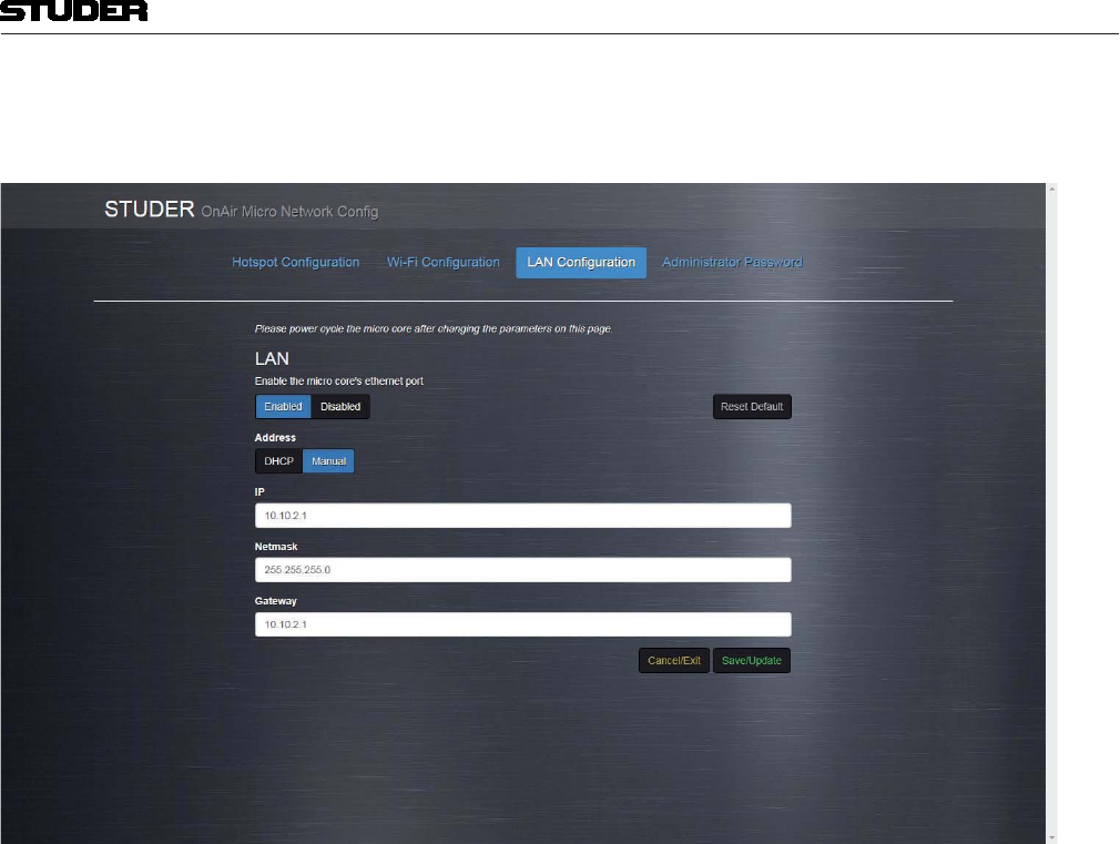
Micro Series
Micro Series 1-67
Document generated: 04.10.17 SW V1.2
LAN Configuration Page
Enable/Disable This page allows to enable or disable the LAN network. The LAN section
can be active in addition to the Hotspot/Wi-Fi section.
Address Lets you chose wether the IP address is automatically received from the net-
work (DHCP), or wether it is a manually entered, fixed address.
IP If a manuall IP address is chosen, it must be entered here.
Netmask This is the submask of the manually enetered IP address (normally
255.255.255.0 )
Gateway Here a gateway address can be entered if needed.
Please note that the network section of the computer device that is used to
control the Micro Core must be configured to match the LAN settings that are
entered here. The IP address must be different from the Micro Core’s address,
but ist must be in the same subnet.
Example : When the Micro Core’s IP address and netmask is : 10.10.2.1 / 255.255.255.0
, then the computers address could be 10.10.2.5 - where the first three num-
bers of this address must be identical to the Micro Core’s address : 10.10.2.
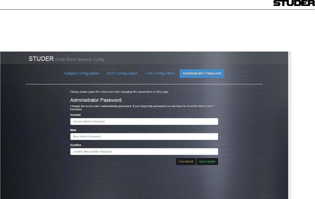
Micro Series
1-68 Micro Series Document generated: 04.10.17
SW V1.2
Administrator Password Page
Here, the password for the Network Config page access can be changed .
The default password is : admin
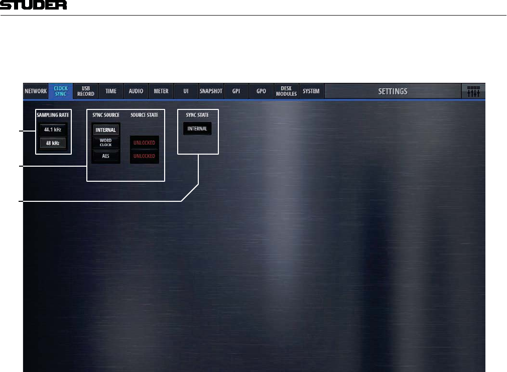
Micro Series
Micro Series 1-69
Document generated: 04.10.17 SW V1.2
On the Clock Sync tab, the sampling rate as well as the sync options can be
found.
1
2
[1] Sampling Rate Sets the sampling rate to either 44.1kHz or 48 kHz.
[2] Preferred Sync Source selection The mixer’s preferred sync source can be chosen here. As the standard, the
internal sync generator is used. If desired, the mixer can be synchronised to
the clock received on either the Wordclock-, or one of the AES inputs. The
Source State indicators then show the state of each possible sync source.
The sync logic makes sure that the preferred sync source becomes active if
there is a valid signal with the desired sampling rate. If the preferred sync
source is not valid, the sync logic switches to the internal sync generator.
[3] Sync State This is the display of the current sync source.
If e.g. the selected sampling rate is 48kHz and word clock is the selected
Sync Source, but the external word clock provides 44.1kHz or is even not
available, the Sync State will indicate INTERNAL, as the sync logic defaults
to internal clock generator running on the selected sampling rate.
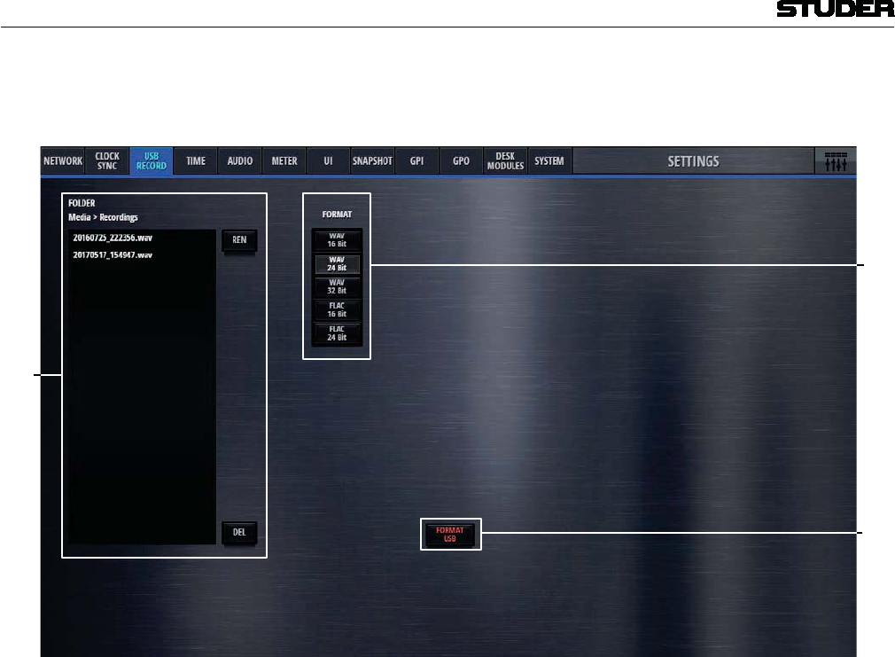
Micro Series
1-70 Micro Series Document generated: 04.10.17
SW V1.2
On the USB Record tab, all necesarry parameters for the USB recording can
be set.
1
2
[1] Folder In this window all recorded files that are found on the USB media are shown.
The folder where the recorded files are stored is called “Recordings”. If there
is no such a folder on the USB media, it will be created automatically. Also,
recorded files can be renamed or deleted.
[2] Format Selects the file format of the recordings.
WAV Linear, uncompressed audio file.
FLAC Lossless compressed audio file.
[3] Format USB This button allows to format the inserted USB media with the FAT-32 file
system format. All data on the USB media will then be deleted.
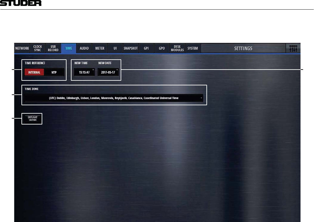
Micro Series
Micro Series 1-71
Document generated: 04.10.17 SW V1.2
The Time tab hosts all controls to set the time settings of the mixer.
[] []
[2]
[3]
[1] Time Reference Allows to select either an external NTP or the internal time reference. If NTP
is selected, an additional field appears where the address of the NTP time
server can be specified.
[2] Time Zone Selects the UTC time zone.
[3] Daylight Saving Allows to switch daylight saving either on or off. Daylight saving is active
when the button is illuminated.
[4] New Time Allows the operator to adjust the time and date.
New Date
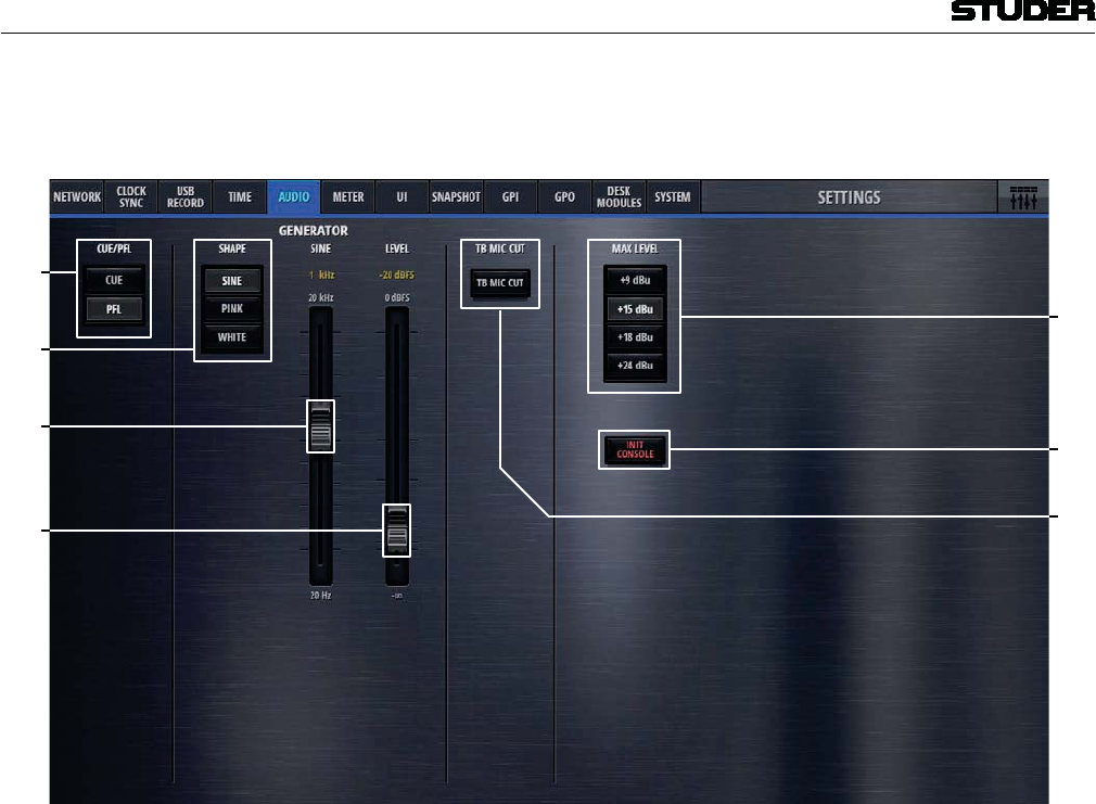
Micro Series
1-72 Micro Series Document generated: 04.10.17
SW V1.2
The Audio tab has controls for the PFL mode, internal test tone generator,
setting of the analog I/O ports, TB cut and console initialisation.
1
2
[1] CUE/PFL Selects the PFL behaviour. CUE mode lets the operator listen to the post-fader
signals. PFL is pre-fader-listening.
[2] Generator Shape Allows the operator to select either a sine-wave, pink noise or white noise as
the test tone signal.
[3] Frequency This fader controls the sine-wave-generators frequency. The possible fre-
quency range is from 20Hz to 20kHz.
[4] Level The level fader controls the test tone level. It ranges from -infinity to 0dBFS.
[5] Max Level The Max Level setting defines the systems reference line level for 0dBFS.
This is a global setting. But it can also be set on a channel by channel basis.
This setting needs to correspond with the actual level calibration of the ana-
logue input- and output interfaces. As a standard, the Micro Core is shipped
with all analogue levels calibrated to +9dBu. This means that the highest
possible analog signal that leaves the mixer is +9dBu. And it also means, that
signals which are higher than +9dBu will clip the A/D converters.
[6] Init Console The Init button resets all mic gain values in reference to the seleted Max Level
setting.
[7] TB Mic Cut TB Mic Cut is a security feature to prevent a TB signal from going on-air.
The TB Mic Cut function can be activated/deactivated here. As soon as the
TB is activated to anywhere, the associated channel will be cut pre-fader.
This is valid for channels of role DJ, Guest, Input for Send 1..4.
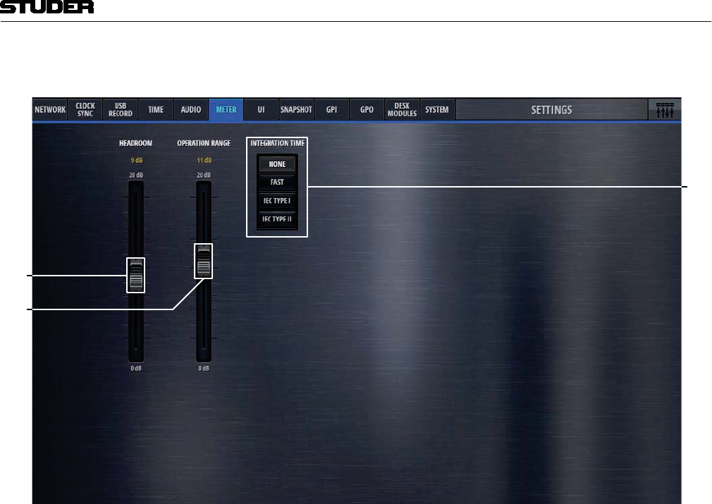
Micro Series
Micro Series 1-73
Document generated: 04.10.17 SW V1.2
On the Meter tab, the parameters of the mixer internal metering can be set.
1
2
[1] Headroom Sets the top, red area of the meter. The default value is 9dB, this means that
meter values above -9dBFS are then displayed in red meter bar elements.
[2] Operation Range This is the mid section of the meter where the signal is displayed in green
meter bar elements.
Meter bar elements below the operation range are yellow.
[3] Integration Time Sets the meters integration time.
None 0 ms
Fast 1 ms
IEC Type I 5 ms
IEC Type II 10 ms
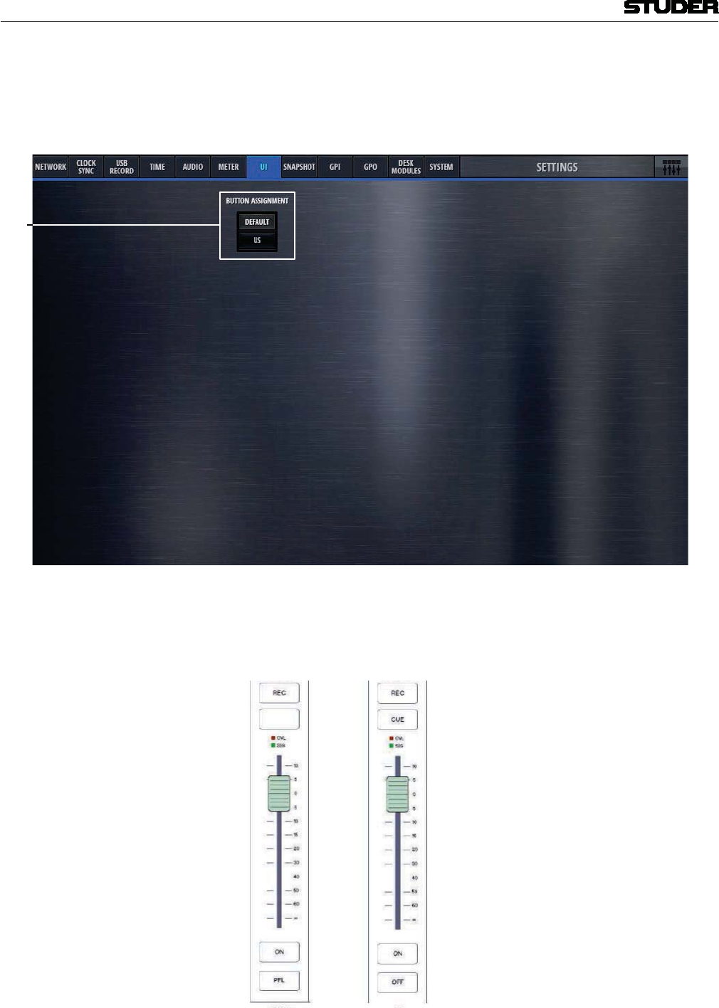
Micro Series
1-74 Micro Series Document generated: 04.10.17
SW V1.2
The UI settings tab allows to switch the button assignment of the User Inter-
face from default to US.
The chosen mode is valid for the GUI as well as for the hardware Micro Fader
module.
1
[1] Button Assignment Changes the button assignment mode.
Default US
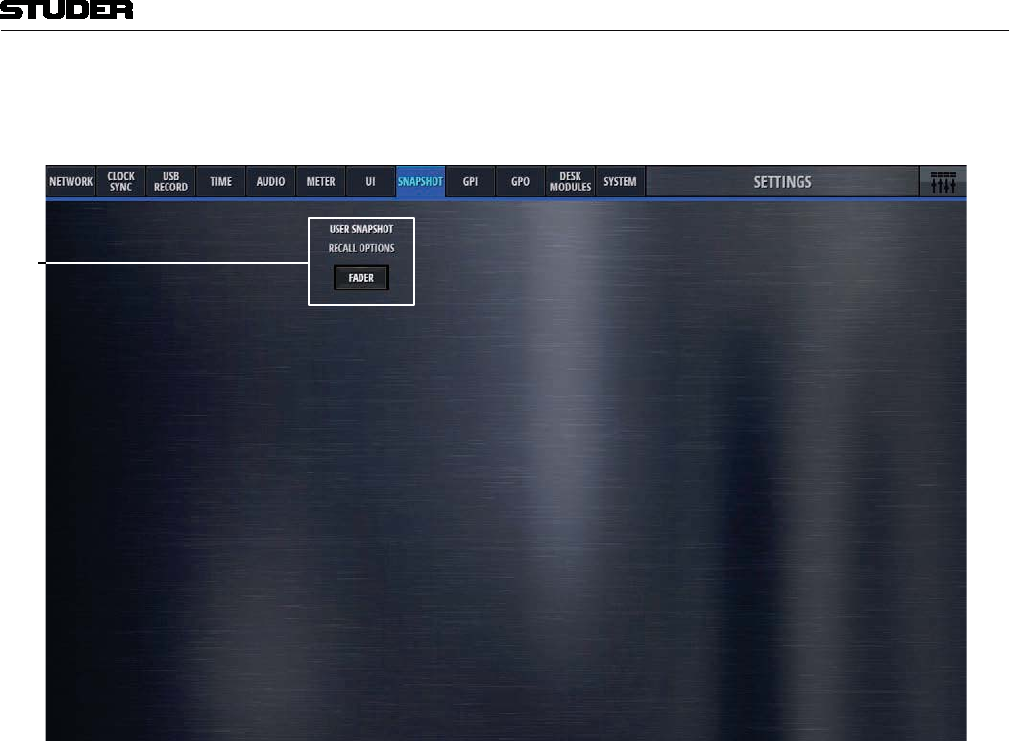
Micro Series
Micro Series 1-75
Document generated: 04.10.17 SW V1.2
The Snapshot tab allows to set snapshot recall options.
1
[1] Fader This button allows to protect all input channel faders from snapshot recall.
Note : Please note that any channel fader that is On-Master, is protected from snap-
shot recall anyway - irrespective of this setting.
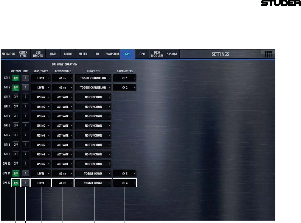
Micro Series
1-76 Micro Series Document generated: 04.10.17
SW V1.2
The GPI tab is the page where all general purpose input functions are con-
figured and activated.
1[2] [3] [ ] [ ] [ ]
[1] On/Off Lets the operator activate the GPI. The button is illuminated when active.
[2] Dir The Polarity of the signal at the input pin: High=Active is positive-,
Low=Active is negative polarity.
[3] Sensitivity Considering the polarity, the sensitivity defines whether the input function
reacts on Rising edge, Falling edge or Level changes.
[4] Action Action is only relevant, if sensitivity is falling edge or rising edge. In this case,
it defines if the input function activates (Activate), deactivates (Deactivate)
or toggles (Alternate) the parameter value. Usually Action is set to Alternate.
Activate and Deactivate are used in case where two GP Inputs for the same
GPInput Function are available, e.g. ON button and OFF button.
[4] Time Defines the time a pulse at the input pin must have at least to be interpreted
as momentary. Time is only relevant if Sensitivity is Level.
Time = 0 : Momentary only. Set the parameter according to Level
Time > 0 : Momentary and Latching. Momentary (if level is active for more
ms than Time). Set parameter value according to Level. Latching (if level is
active less for less ms than Time) toggle the parameter value (on falling edge)
If the pulse is shorter than the specified Time, the Function is latched.
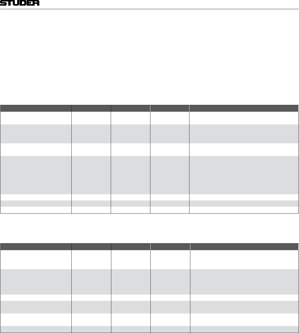
Micro Series
Micro Series 1-77
Document generated: 04.10.17 SW V1.2
[5] Function Defines the function that is triggered from the GPI
[6] Parameters Depending on the GPI Function, a parameter of the function can be chosen
here. (E.g. a channel number).
The two following tables show all Input Functions :
Momentary only or momentary and latching functions :
Function Argument 1 Argument 2 Argument 2 Description
CHANNEL ON Channel 1..12
Send 1..4 -- - Activate/Deactivate the specified On/Off
CHANNEL PFL Channel 1..12
Send 1..4
PRG, REC - - Activate/Deactivate the specified PFL On/Off
COUGH Channel 1..12 - - Activate/Deactivate TB Mic Cut of the specified Chan-
nel
TALKBACK
Source :
TBfromCh1..12
TBfromExtern
Destination :
TBtoCR
TBtoDJ
TBtoGuest
TBtoSend1..4
TBtoExtern
-Activate/Deactivate TB from specified source todes-
tination
LSP CUT - - - Activate/Deactivate the loudspeaker Cut
LSP DIM - - - Activate/Deactivate the loudspeaker Dim
Event driven functions:
Function Argument 1 Argument 2 Argument 2 Description
SET CR MON SRC PRG, REC
Send1..4
EXTERN Set the specified source for the CR monitoring
SET GUEST MON SRC
PRG, REC
Send1..4
EXTERN
FOLLOW CR
Set the specified source for the Guest monitoring
LOAD SNAPSHOT Snapshot name Recall the specified snapshot
TRACK PLAYER NEXT
STOP Start the next track in the Playlist
Stop the Playlist
RESET PFL Reset any active channel PFL. (Similar to the Reset
PFL button on the GUI).
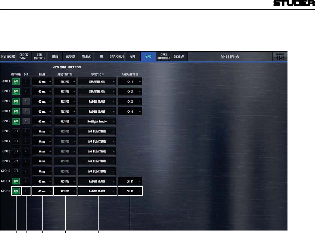
Micro Series
1-78 Micro Series Document generated: 04.10.17
SW V1.2
The GPO tap is the page where all general purpose output functions are con-
figured and activated.
1 2
[1] On/Off Lets the operator activate the GPIO. The button is illuminated when active.
[2] Dir The Polarity of the signal at the input pin: High=Active is positive-,
Low=Active is negative polarity.
[3] Time Depending on the Time, the Output Logic either operates as level- or edge
sensitive.
[4] Sensitivity The Sensitivity defines how the value affects the signal at the output pin.
Possible values are RISING EDGE, FALLING EDGE or LEVEL.
[5] Function Chooses the function that triggers the GPO signal.
[6] Parameters Parameters defines the channel number on which the function is based on.

Micro Series
Micro Series 1-79
Document generated: 04.10.17 SW V1.2
The following table shows all output functions :
Function Argument 1 Argument 2 Argument 2 Description
CHANNEL ON Channel1..12
Send1..4 Reflects the On/Off status of channels and sends.
CHANNEL PFL Channel1..12
Send1..4
PRG, REC
Reflects the PFL On/Off status of channels, send and
FADERSTART Channel1..12 Reflects the AND combination of channel’s
On/Off- and fader status.
FADERSTART+PFL Channel1..12 Same as FADERSTART, but also active when chan-
nel’s PFL is active. (FADERSTART OR PFL.)
CHANNEL ON MASTER Channel1..12 The function becomes active when the specified
channel is either on PRG or REC output.
(Channel On-Master condition)
RedLight Studio
The function becomes active when a microphone is
either on PRG or REC output.
In other words, at least one channel with role DJ
or Guest fulfils the Channel On-Master condition.
ONAIR The function becomes active when at least one chan-
nel is OnAir.
RECORD
The function becomes active when at least one chan-
nel is on the REC output.
One of the the following conditions must be fulfilled
for at least one channel:
AND
the fader is open
AND
the channel is assigned to REC bus
AND
the REC fader is open
AND
the fader is open
AND
Off Air Record is active on the channel
AND
the REC fader is open
TALKBACK
Source :
TBfromANY
TBfromCH1..12
TBfromEXTERN
Destination :
TBtoANY
TBtoCR
TBtoDJ
TBtoGUEST
TBtoSend1..4
TBtoEXTERN
The function becomes active when TB from Source to
Destination is active.
The GPOutput can be used to control external
intercom systems for TB button illumination.
The function does not indicate incoming
TB.
CR MON SRC
PRG, REC
Send1..4
EXTERN
PFL
The function becomes active when the specified
monitoring source is currently active on the CR moni-
toring.
GUEST MON SRC
PRG, REC
Send1..4
EXTERN
FOLLOW CR
The function becomes active when the specified
monitoring source is currently active on the Guest
monitoring.
PFL ACTIVE The function becomes active when any channel PFL
is active.
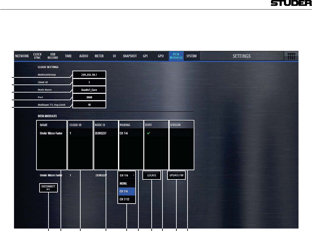
Micro Series
1-80 Micro Series Document generated: 04.10.17
SW V1.2
The Desk Modules tap is the page where one or two Micro Fader modules
can be configured to be used with the Micro Core.
1
2
12 1 1 1 1 11
[1] MulticastGroup The multicast group address setting used for the communication to the Micro
Fader modules can be entered here.
[2] Cloud ID Current Cloud ID of the Core
[3] Node Name Shows the Micro Core’s Node_Name
[4] Port Displays settings of the Cloud communication
[5] Multicast TTL Hop Limit Displays settings of the Cloud communication
[6] Name Shows the Node_Name as configured in the Setup of the Micro Fader module
[7] Cloud ID Current Cloud ID of the Micro Fader module
[8] Node ID Node ID of the Micro Fader module
[9] Pairing The column shows the pairing state of a Micro Fader module
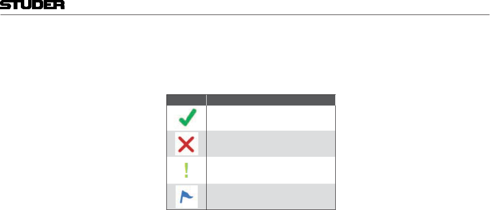
Micro Series
Micro Series 1-81
Document generated: 04.10.17 SW V1.2
[10] State Shows the current Connection/Pairing state of Micro Fader modules within
the network.
Icon Description
Paired to this Core - Connected
Paired to this Core - disconnected
Paired to this Core - connected, but
different Cloud ID
Not paired
[11] Version The column indicates the Micro Fader module firmware version for each
Micro Fader module available on the network.
[12] Disconnect All This button disconnects all paired Micro Fader modules, which are currently
available on the network.
[13] Channel Selection ComboBox It is used to pair or un-pair a Micro Fader module.
[14] Locate the LOCATE function is activated on the corresponding Micro Fader module
- the Micro Fader module will flash for five seconds.
[15] Update FW It allows updating the firmware on each Micro Fader module which is paired
to the Micro Core.
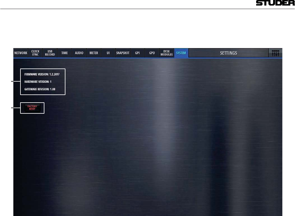
Micro Series
1-82 Micro Series Document generated: 04.10.17
SW V1.2
The System tab on the settings page displays current FW and HW versions
and lets the operater reset the console to factory settings.
1
2
[1] Revision Status Displays current Firmware, Hardware and Gateware version numbers.
[2] Factory Reset Resets the mixer to factory settings.
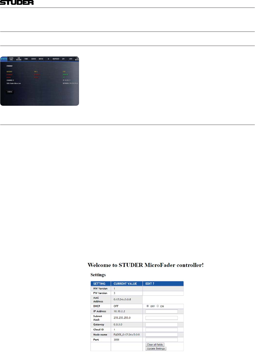
Micro Series
Micro Series 1-83
Document generated: 04.10.17 SW V1.2
3 SETUP
3.1 Setting up the Network
To configure all network settings, please go to the Settings page. There, on
the Network tab, you can configure the network settings to your work with
your network environment.
Please see in chapter 1.5 how the Micro Core can be used in a network, and
then in chapter 2.4 how the settings are configured.
3.2 Setting up the Micro Fader modules
To configure one or two Micro Fader modules that are to be used with the
Micro Core, please go to the Settings page. There, on the Desk Modules tab,
you see all available Micro Fader modules, and you can assign a range of
channel strips to one or two of them. This comfoguration process is called
“pairing”.
Please see in chapter 2.4 how these settings can be configured.
Micro Fader Web GUI If a browser is prompted to the standard IP address of a Micro Fader module
(10.10.2.2) - the settings page of the connected Micro Fader module is
shown.
In the page, the device settings can be changed and updated :
Important : After changing any of the Micro Fader’s settings, first click on the Update
Settings button, and then on the Reboot Device button. Only after a reboot
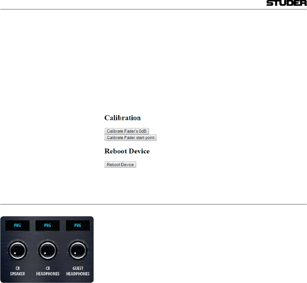
Micro Series
1-84 Micro Series Document generated: 04.10.17
SW V1.2
of the Micro Fader module, all of the changed settings will be applied.
Note : It is necessarry to change the IP address of one Micro Fader module, if two
Micro Fader modules are to be used together. (This needs to be done before
the Micro Fader modules can be assigned to the Micro Core.)
Fader Calibration The fader’s 0dB position can be calibrated.
And the fader start point can also be calibrated - which is the position where
the fader start signal is triggered when opening the fader from -infinity
towards 0 dB.
3.3 Setting up the Monitoring
In total, there are two monitoring sections that can be used within the Micro
Core.
The actual physical outputs that are used by these two monitoring sections
can be freely assigned.
Step 1 Chose the monitoring section that you would like to configure.
Step 2 What should be connected ?
- Active loudspeaker
- Headphone
- Meter
Step 3 What physical connector ?
Step 4 Assign the output :
This is done on the CR Config page, on the Targets tab.
Any of the outputs viewable on this page can be used :
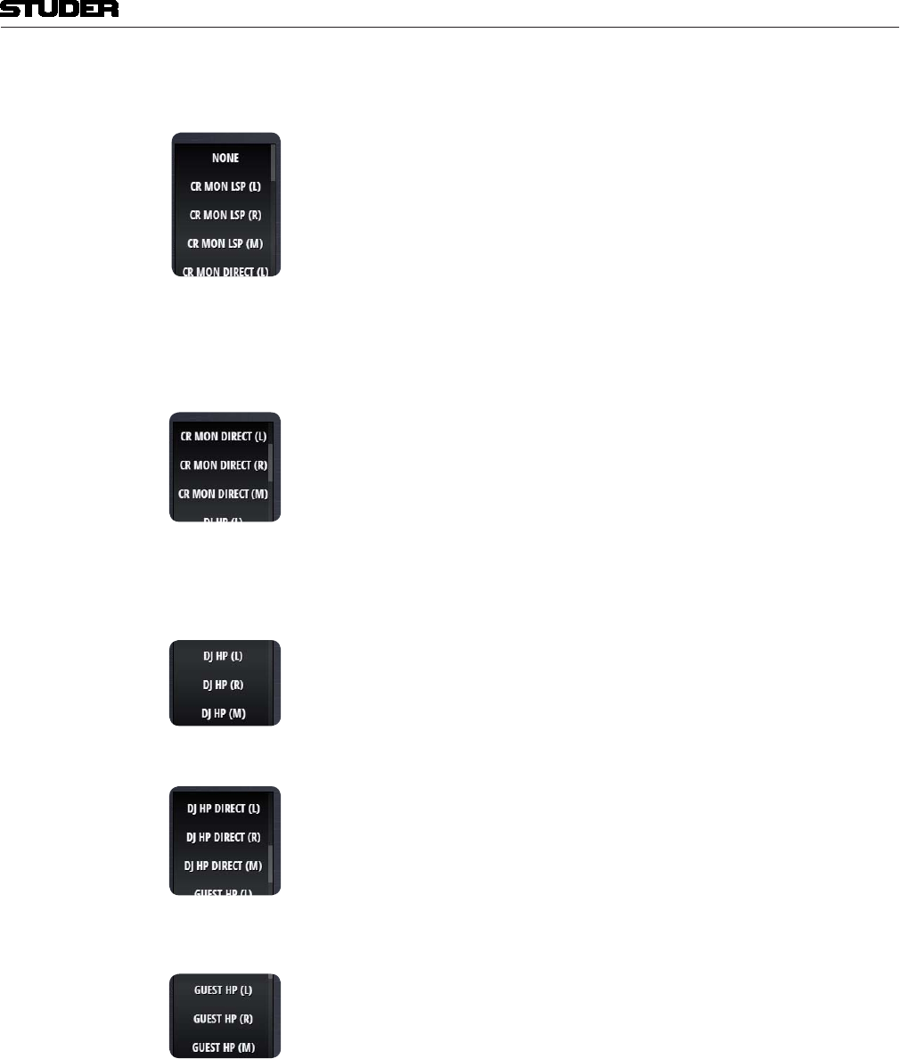
Micro Series
Micro Series 1-85
Document generated: 04.10.17 SW V1.2
The selectable sources for the monitoring sections are the following :
CR MON LSP (L)
CR MON LSP (R)
CR MON LSP (M)
These are the outputs of the CR monitoring section that are meant for a direct
connection of an active loudspeaker. Normally, the left and right speakers
are wired individually. The two stereo signals are downmixed internally to a
mono output (on the source marked M). This source can be used if a single
mono speaker will be used as CR mon speaker.
CR MON DIRECT (L)
CR MON DIRECT (R)
CR MON DIRECT (M)
The sources above, named DIRECT, are providing the same signal as CR
MON LSP, but without level control. These are normally used to connect a
meter that measures the level of the currently selected CR source. Be careful
not to connect an active loudspeaker to such a DIRECT source, as the signal
is fullscale and no level control is possible.
DJ HP (L)
DJ HP (R)
DJ HP (M)
These are the outputs carrying the HP signal of the Control Room Monitoring.
DJ HP DIRECT (L)
DJ HP DIRECT (R)
DJ HP DIRECT (M)
The HP signal of the Control Room Monitoring is also available as DIRECT
signal that has no volume control. This could be used if fed to a remote HP
amplifier when the DJ is remotely operating the Micro Core.
GUEST HP (L)
GUEST HP (R)
GUEST HP (M)
The GUEST HP Monitoring section only has a volume controlled output.
When the outputs are assigned as desired, the Config pages of the monitoring
sections can be used for further configuration.
CR Monitoring Options page :
Monitoring Source Here the actual monitoring source is chosen.
Cut This button lets the operator manually cut the CR monitor.
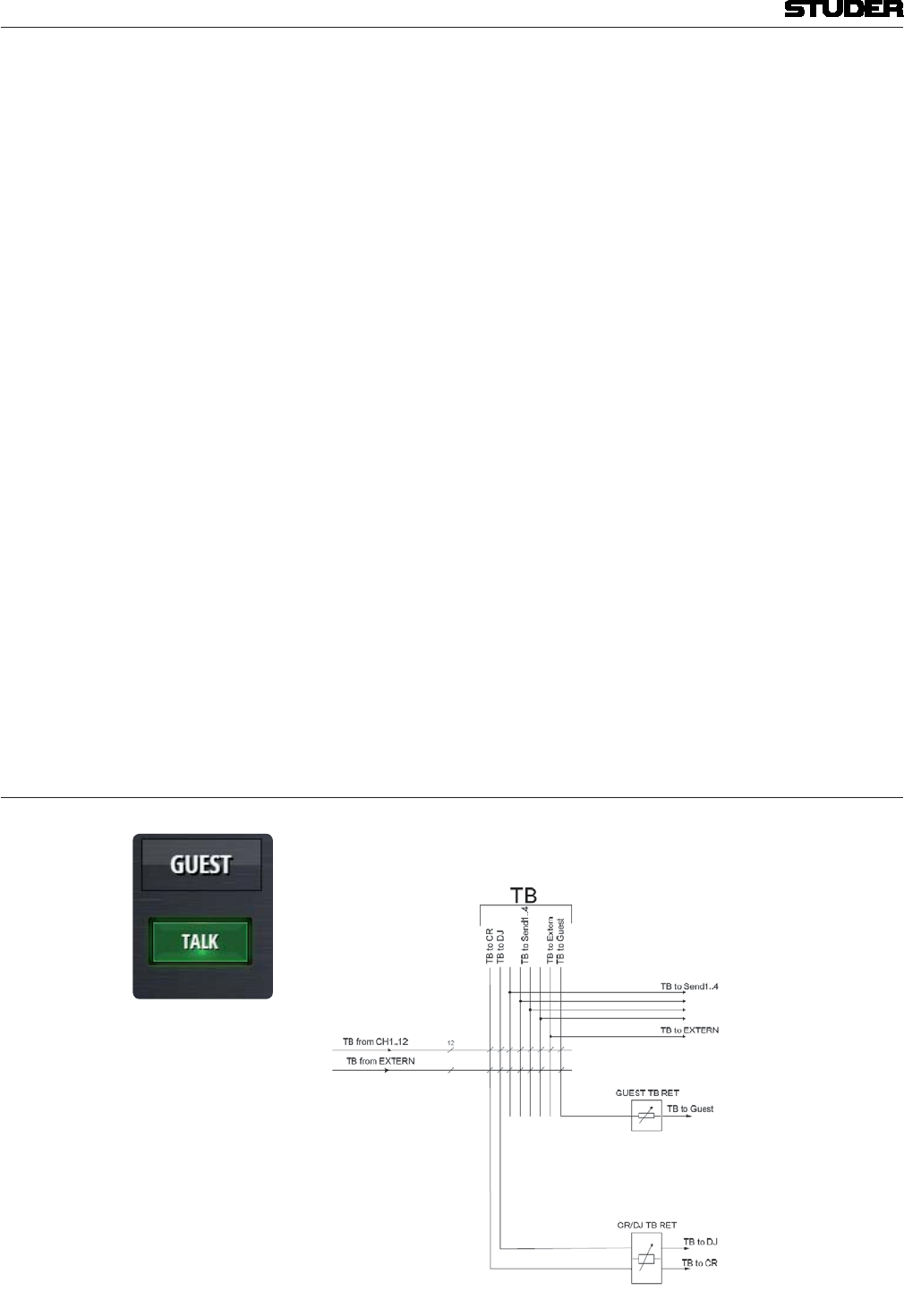
Micro Series
1-86 Micro Series Document generated: 04.10.17
SW V1.2
PFL to Mon With this option active, the current CR monitoring source gets replaced with
the PFL signal, as long as any PFL is active.
Mono This button mixes the stereo CR source down to a mono signal for both, CR
speakers and CR headphones.
HP Split With this mode active, the PFL signal will be fed to the left channel of the
headphone, if PFL is active on any channel. On the right channel, still the pre-
viously selected CR source will be heard. Both signals are then downmixed
to mono.
Once PFL is released, the current CR source will be heard in stereo again.
If PFL is already selected as the CR source, actually pressing PFL on any
channel will not change the stereo PFL bus as the monitoring source.
Guest Monitoring Options page :
Monitoring Source Here the actual monitoring source is chosen. FOLLOW CR choses the cur-
rently active source of the CR monitoring section.
Note : TB return signals are heard via the two monitoring sections :
Please note that TB return signals are fed to the CR monitoring section in
case of TB to the DJ.
In case of TB to Guest, TB return signals are fed to the guest monitoring sec-
tion.
When a TB return is active, the current monitoring signal will be dimmed by
20dB.
3.4 Setting up TB
The Micro Core provides a powerful internal TB matrix.
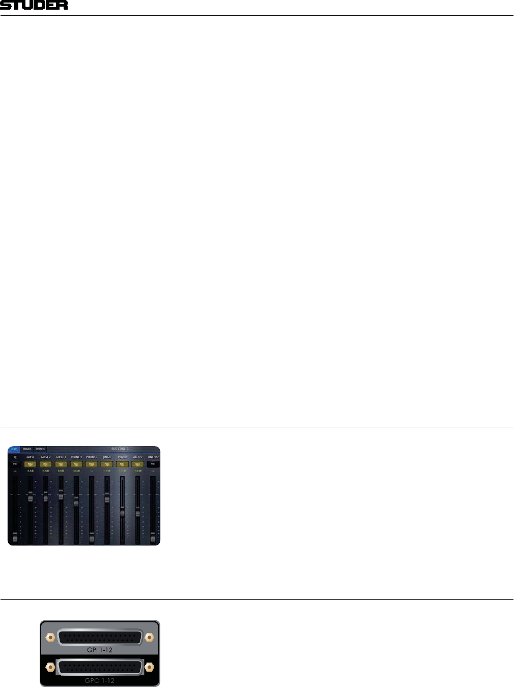
Micro Series
Micro Series 1-87
Document generated: 04.10.17 SW V1.2
The DJs TB possibilities The DJ can use the Talk buttons on channels of the role “Guest” and “Inputs
for Send” and talk to the Studio guests and outside sources such as a telefone
guest.
These Talk buttons automatically appear on the GUI. They are meant to be
used by the DJ and therefore use the DJ Mic Input as the source signal.
The DJ can also talk to the External TB target (TB to Extern). The physical
output, where this signal leaves the Micro Core can be assigned freely. Any
of the outputs viewable on the Targets page can be used.
TB TO EXTERN is the name of the signal that has to be assigned.
The TB possibilities of others TB from other channels than th DJ’s input channel can only be activated by
GPI’s.
Via GPI, TBfromCH 1-12 as well as TBfromExtern can be activated to speak
to the following possible targets :
TBtoCR
TBtoDJ
TBtoGuest
TBtoSend1
TBtoSend2
TBtoSend3
TBtoSend4
TBtoExtern
3.5 Setting up N-1 / Sends
There are four send busses within the Micro Core. Each bus can either be
used as an Aux bus or as a N-1 bus.
The setup of all parameters concerning the typ of the bus, as well as the actual
mix from the input channels, can be done in the Config page of the bus. Please
see chapter 2.3.2.
3.6 Setting up GPIOs
GPIO (GeneralPurposeInputs and Outputs) are an effective interface for the
mixer to communicate with the studio environment. The upper d-type con-
nector hosts 12 pairs of pins where a voltage pulse or level can be detected
(GPI). The lower d-type connector hosts 12 pairs of pins where a relay can
establish a connection between the pins (GPO).
GPI’s There are many mixer internal functions that can be used via the 12 GPI’s.
Mixer internal functions that can be triggerd via GPInputs are called Input
Functions.
Please refer to the table in chapter 2.4 for a complete description of all Input
Functions.
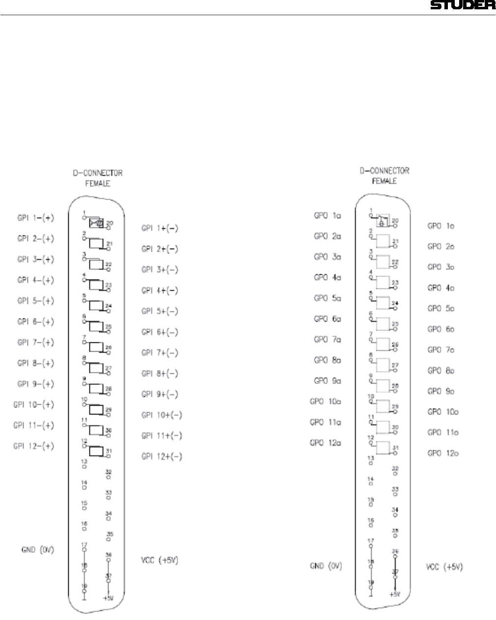
Micro Series
1-88 Micro Series Document generated: 04.10.17
SW V1.2
GPO’s There are many mixer internal functions and states that can activate a GPO :
Mixer internal functions that can switch a GPOutput are called Output Func-
tions.
Please refer to the table in chapter 2.4 for a complete description of all Output
Functions.
Connector Pinout :
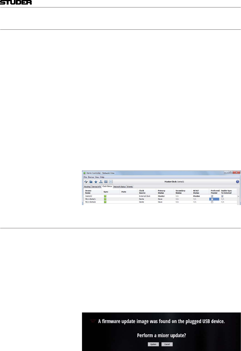
Micro Series
Micro Series 1-89
Document generated: 04.10.17 SW V1.2
3.7 Setting up Dante
To control and setup the Dante network, please use the Dante Controller
software that can be downloaded under :
https://www.audinate.com/products/software/dante-controller
Within the Dante Controller software, all network devices are displayed in a
matrix and you can make the signal routing from and to the different devices.
Within the Micro Core, the received Dante streams are available from the
input ports AES67/DANTE #1 - 8.
The signals that are assigned to the output ports AES67//DANTE#1-8 will
be transmitted as Dante streams.
There are two AES67/Dante ports, which means that the Dante Controller
will see two Micro Core devices when both ports are connected to the Dante
network.
Note : Since the built-in Dante ports do not accept external sync reference (Enable
Sync to External), it is not meaningful to use the Micro Core as Preferred
Master within a Dante/AES67 network.
3.8 Firmware update
To perform a software update of the Micro Core, the latest software file can
be downloaded from the Studer website. The software file has a .zip file
extension and is named like this :
oamupdate-X.X.XXXX-usb.zip
Where the Xs stand for the latest software version.
This file can be copied to the root folder of a USB media, which then can be
inserted into the Play/Rec USB port of the base unit.
Once the USB media is scanned. the software file is automatically detected
and the update process is started. All following process steps are then guided
by instructions that are shown on the screen or GUI of the Micro Core.

Micro Series
1-90 Micro Series Document generated: 04.10.17
SW V1.2
3.9 Emergency factory reset
Full factory reset The following scenario executes a full reset including reloading the factory
firmware and factory default settings :
Step 1 Connect a USB keyboard to the Micro Core’s GUI connectors.
Step 2 During startup, as soon as the CORE LED lights up, press the F12 key.
(Press the key in the same way as on a personal computer to enter it’s BIOS
settings.)
As soon as the Micro Core detects the F12 key pressed during startup, it
reloads the factory firmware and resets all parameters to factory default.
Reset of network settings The following scenario resets the network settings to factory default :
Step 1 Connect a USB keyboard to the Micro Core’s GUI connectors.
Step 2 During startup, as soon as the CORE LED lights up, press the DEL key.
(Press the key in the same way as on a personal computer to enter it’s BIOS
settings.)
As soon as the Micro Core detects the DEL key pressed during startup, it
resets the network settings to factory defaults and confirms it by flashing the
blue WiFi LED for 5s.
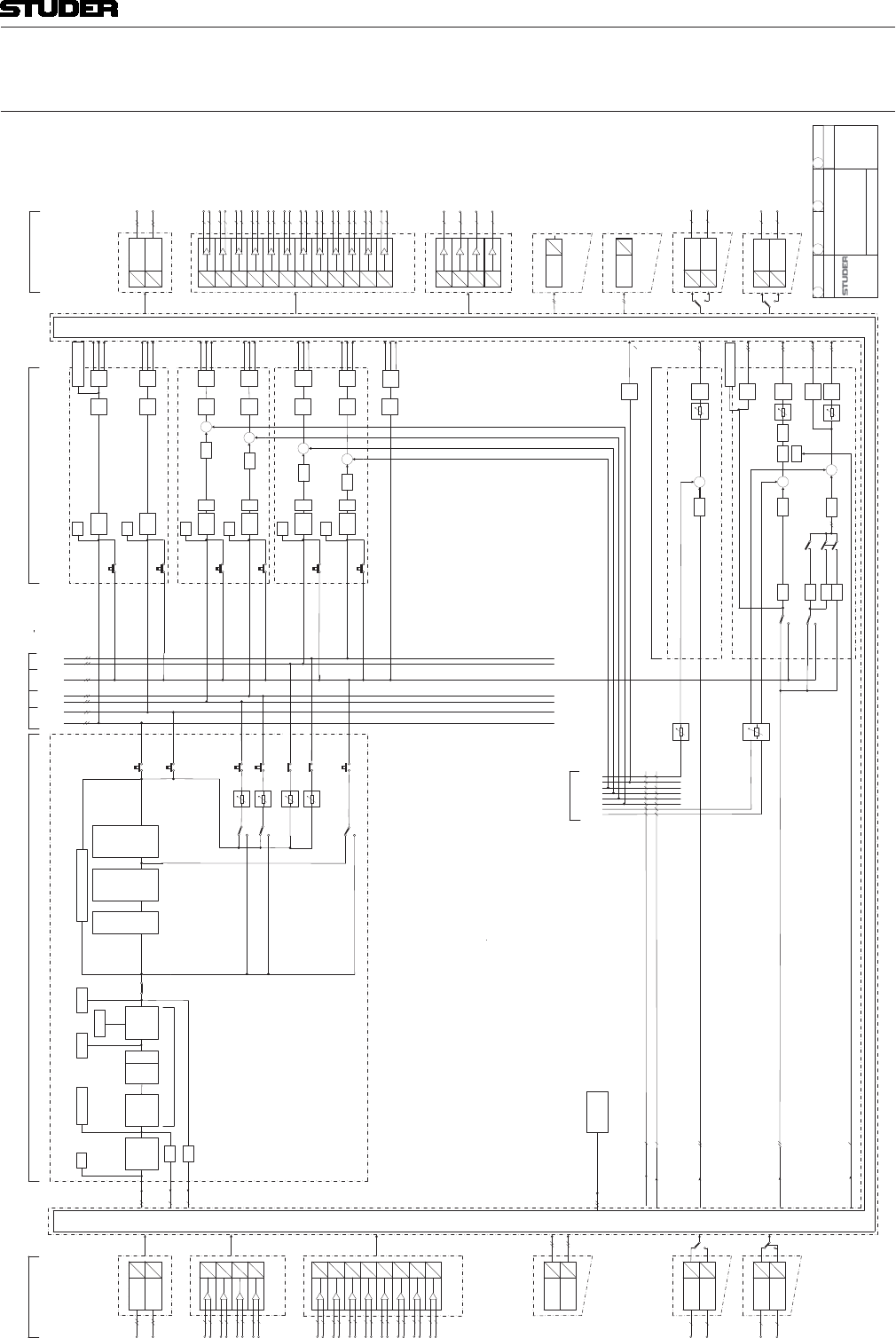
Micro Series
Micro Series 1-91
Document generated: 04.10.17 SW V1.2
4 BLOCKDIAGRAM
INPUTS CHANNELS -BUSSES MASTER/SEND OUTPUTS
AU 1
REC
AU 2
PFL
N-1 1
N-1 2
L (M)
REC MASTER
TB
DIM
SEND 1 (AUX)
TB
DIM
SEND 2 (AUX)
PFL
OnAir Micro
Regensdorf
Swit erland
BLOC DIAGRAM
AUDIO
CR MON SOURCE
TB to E TERN
TB
TB to DJ
TB to Extern
TB to Send1..4
TB from E TERN
DD
DD
DD
SFC
AES (IN)
DD
SFC
AES (OUT)
1/2
3/4
1/2
3/4
PFL
PRG
AD
HQ MIC IN
AD
AD
AD
5
6
LINE OUT
5
DA
6
DA
7
DA
8
DA
LIM
Test Generator
SINUS
WHITE NOISE
PIN NOISE
CH INP
M/S R (M)
M
L (M)
LIM M/S R (M)
M
L (M)
M/S R (M)
M
L (M)
M/S R (M)
M
CR/DJ TB RET
FADER
PRG MASTER
PFL
PFL
Master AU Listen N-1
TB
DIM
SEND 3 (N-1)
TB
DIM
SEND 4 (N-1)
ONFADER
FADER
FADER ON
FADER
FADER
ON
ON
PFL
PFL
DANTE / AES67
DD
4
d
DD
4
d
DANTE
AES/67
DANTE / AES67 (OUT)
DDd
4
DDd
4
DANTE
AES/67
CR LSP Left
PHASE
STEREO
CAL DEESSER EQ
4 Band
HP LP
D NAMIC
Gate Comp
FADER BALANCE CHANNEL
ON/OFF
PRG
SEND 1 (AU )
SEND 2 (AU )
PFL
AF
PF
PF
AF
STEREO CHANNEL 1 to 12 CUE
PFL
REC
SEND 3 (N-1)
SEND 4 (N-1)
GRM Meter
PROCESSING
OVL
TB from CH1..12
DJ HP
CR MON LSP
Split Off
Split On
GUEST HP
CONTROL ROOM
Mono CUT
HP Split Mode
CR TB
DIM
Mono
Mono
DJ TB
DIM
C1
9
DA
10
DA
11
DA
12
DA
DJ HP
GUEST HP
L
DA
R
DA
L
DA
R
DA
CR LSP Right
HP OUT
GUEST SOURCE
GUEST HP
TB
DIM
LIM
LIM
LIM
LIM
TB to CR
PFL active
PFL to MON
No PFL active
GUEST TB RET
EQ
1.0
USB PLA
DD
DD
Jingle
Player
Track
Player
USB PLA
DD
Recorder 1
MONITORING
7
8
AD
AD
AD
AD
1
2
3
4
TB to Guest
Main Meter CR Mon
SIG
Input SIG/Meter
SIG
SIG
SIG
SIG
SIG
In Meter Out Meter Main Meter Program
CR MON Direct Out
TB to Guest
1.2
DJ HP Direct Out
Mono
PFL active
No PFL active
L
R
PFL Bus Mode
AD
AD
AD
AD
9
10
11
12
Mic Gain
PAD
Phantom
1
DA
2
DA
3
DA
4
DA
USB REC
DD
Recorder 2
DANTE / AES67 (OUT)
DDd
4
DDd
4
DANTE
AES/67
DANTE / AES67
DD
4
d
DD
4
d
DANTE
AES/67
1.8
LIM
LIM
LIM
LIM
LIM
LIM
To TB from Mono
TB Mic
Cut
L (M)
R (M)
M
L (M)
M/S R (M)
M
M/S
TB to DJ
TB to CR
12
LINE IN
4 fix Input
Levels
4 fix Output
Levels
Pre-/Post Fader Channel Meter
1.7
LIM L (M)
M/S R (M)
M
RTA
RTA
To CR RTA Mono
CR RTA
17.5.2017/WP 4.10.2017/WP

Micro Series
1-92 Micro Series Document generated: 04.10.17
SW V1.2
5 TECHNICAL SPECIFICATIONS
ic Line Inputs Conditions Details Value
General Conditions: Gain setting 15 dBu 0 dBFS unless otherwise noted
Input Level ange Max. level @ 0dBFS, 86 one-dB steps –60 to +26 dBu
Input Impedance
Fre uency esponse +0 dB / –0.3 dB 20 Hz to 20 kHz
+0 dB / –0.2 dB 30 Hz to 20 kHz
D Noise 1 kHz, –1 dBFS, 15 dBu < –97 dB
20 Hz to 20 kHz, –30 dBFS < –110 dB
Common ode e ection atio (C ) 30 Hz to 20 kHz, full gain range > 70 dB
1 kHz, < -20 dBu, > 35 dB gain 100 dB typ.
Crosstal 1 kHz
E uivalent Input Noise Rsource!"!!# –126 dBu
F e ection RF rejection with common mode choke Yes
Analogue igh-Pass Filter switchable 75 Hz, 12 dB/Oct
Phantom Power switchable 48 V
ero cross detection and Sample old for click free gain changes Yes
Line Inputs Conditions Details Value
a Input Level Max. level @ 0 dBFS, four steps, software controlled +9, +15, +18, +24 dBu
Input Impedance > 10 k
Fre uency esponse 20 Hz to 20 kHz +0 dB / –0.2 dB
D Noise 1 kHz, –1 dBFS, 15 dBu < –97 dB
20 Hz to 20 kHz, –30 dBFS < –110dB
Common ode e ection atio (C ) 30 Hz to 20 kHz, all four gain settings > 60 dB
Crosstal 1 kHz > –110 dB
F e ection Yes
Line utputs Conditions Details Value
a utput Level Max. level @ 0 dBFS, four steps, software controlled +9, +15, +18, +24 dBu
utput Impedance $
Electronically alanced Yes
AES EB Inputs Conditions Details Value
Input Sensitivity 0.2 V
Input Impedance 110
S C ange 32 to 192 kHz
Latency Conditions Details Value
Input to utput Delay Mic In - ADC - DSP - DAC - Line Output 1.8 ms
AES EB utputs Conditions Details Value
utput Level 3 V
utput Impedance 110
Power Supply Conditions Details Value
Primary Input Voltage ange Power supply auto-ranging, with power factor correction (PFC);
EN/UL approved 100 to 240 V AC ± 10%
50 to 60 Hz
Power Consumption Micro Core 100 W
eights Value
icro Core 7 kg

Micro Series
Micro Series 1-93
Document generated: 04.10.17 SW V1.2
6 GLOSSARY
AGC Automatic Gain Control
AES3 AlsoAES/EBU - is a standard interface for digital audio. A stereo audio signal
on a single XLR cable.
Aux Auxiliary mix - an additional mix possibility (four on the Micro Core) that
can be independent of the main PRG master (PRE-Fader Aux) - or that is also
taking the channel fader level into account (POST-Fader Aux).
CUE The CUE button lets the operator listen to the post-fader signals of individual
channels .(As oposed to PFL which is pre-fader-listening.)
CR Control Room monitoring. This is usually the main loudspeaker monitoring
system that is used by the operator or DJ.
Dante Digital audio network through Ethernet cable.
DJ Disc-Jockey - an On Air operator that runs a radio show as a single person.
DSP Digital Signal Processing - the electronic hardware that calculates the audio
processing.
GEQ Graphic Equalizer - an equalizer with 31 filter bands where each band repre-
sents a fixed frequency. The gain sliders of each band are graphically arranged
next to each other - so that the resulting curve of the sliders represents the
GEQ’s filter response.
GPIO General Purpose Inputs and Outputs that can be configured by the operator.
GPI General Purpose Inputs.
GPO General Purpose Outputs.
GUI Graphical User Interface - the actual graphics on the tablet or computer screen
that provides all the control elements of the On Air Micro.
HDMI Interface where a digital screen can be connected (High Definition Multimedia
Interface)
HPF High Pass Filter.
Jingle A jingle is a short song or tune used in advertising and radio production.
N-1 This mode is made for Aux busses that are feeding a return signal to remote
positions. It doesn’t allow the input signal of the remote source to be assigned
to the bus. With this bus mode, the remote source (e.g. a reporter) will never
have his own signal in his return feed. This is optimal to prevent echo’s that
could be introduced through long distance signal transmission.

Micro Series
1-94 Micro Series Document generated: 04.10.17
SW V1.2
Off Air When a channel’s audio signal is not going to the PRG master - this channel
is Off Air.
On Air When a channel’s audio signal is being fed to the PRG master, this channel
is On Air.
On Master When a channel’s audio signal is either on PRG or REC master output
OVL Signal overload indication of a channel.
PFL PFL is pre-fader-listening.
PoE Power over Ethernet - a version of the physical layer of the Ethernet protocol
that carries a supply voltage which allows to power equipment directly from
the Ethernet cable (up to 25.5 W per unit)
PRG The program master bus
REC The record master bus
RTA Real Time Analyzer - a representation of the audio signal where level bars
over the frequency spectrum are calculated in real time.
TB Talkback.
WLAN Wireless Local Area Network - also called Wi-Fi.