Harman UI24RMIXER 24 Channel Digital Mixer/Recorder User Manual
Harman International Industries, Inc 24 Channel Digital Mixer/Recorder
UserManual.wiki
>
Harman
>
UI24RMIXER User Manual
User Manual
Navigation menu
Upload a User Manual
Namespaces
Wiki Guide
HTML
PDF
Info
Views
User Manual
Discussion / Help
Navigation

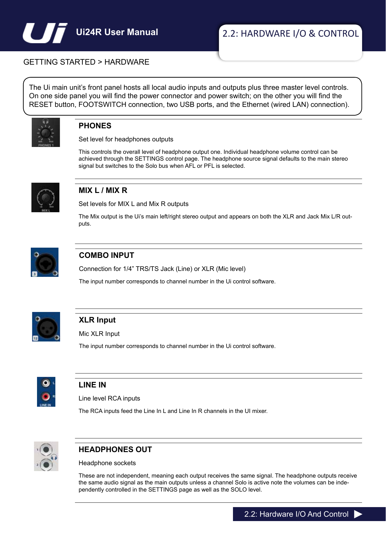
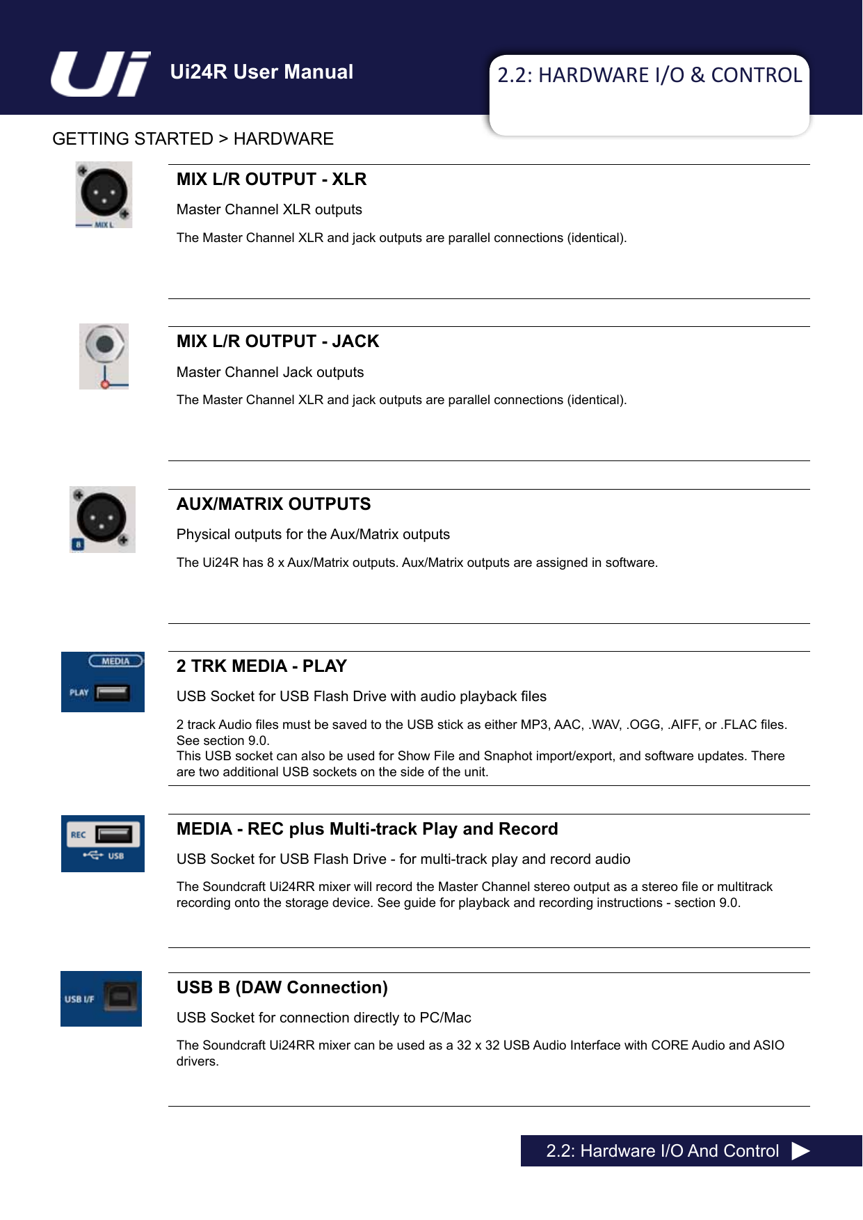
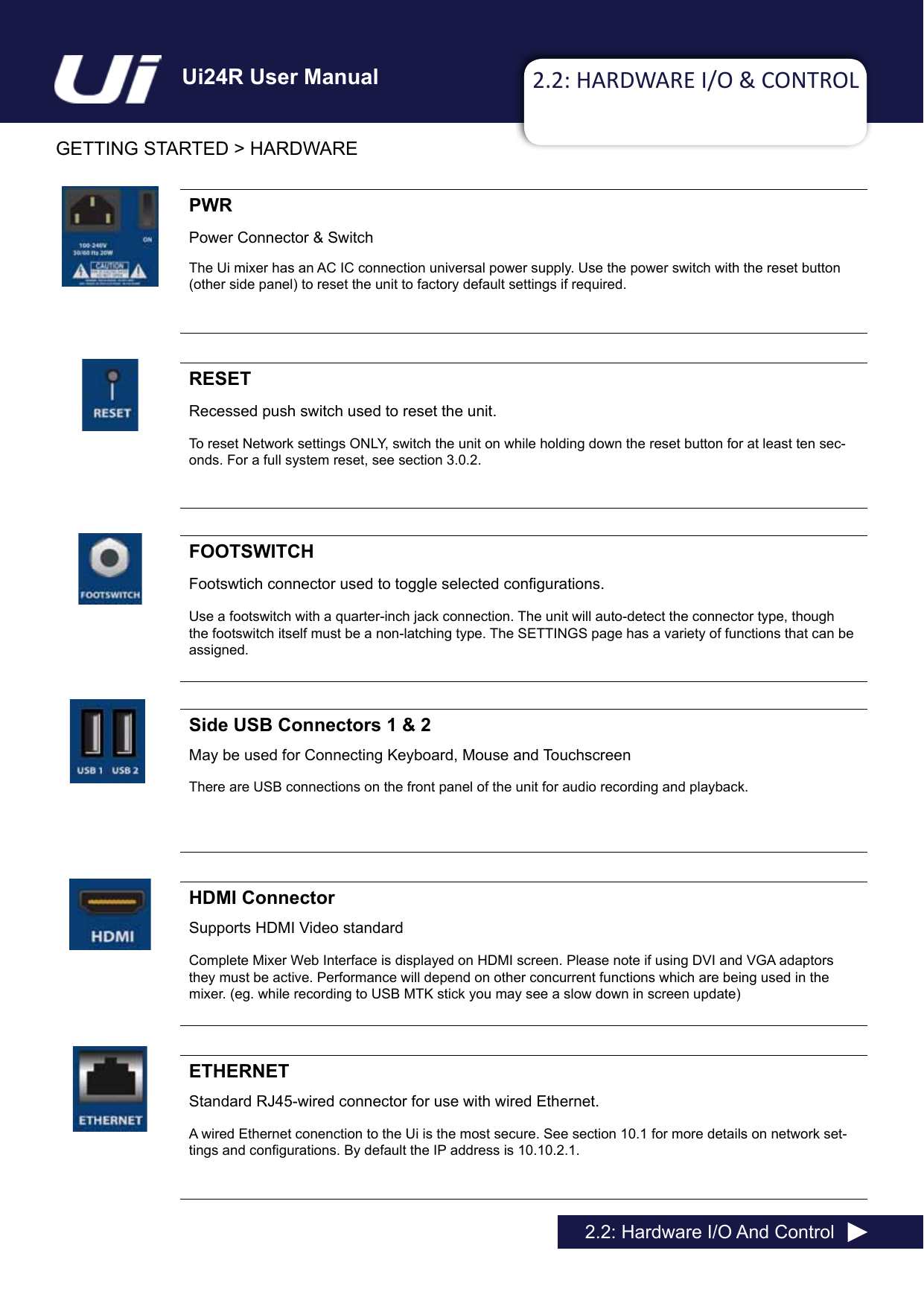
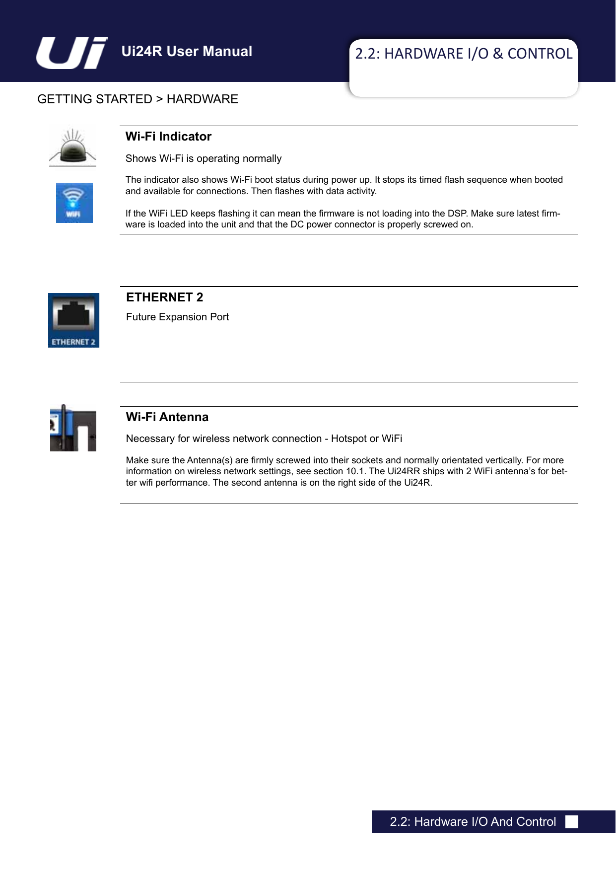
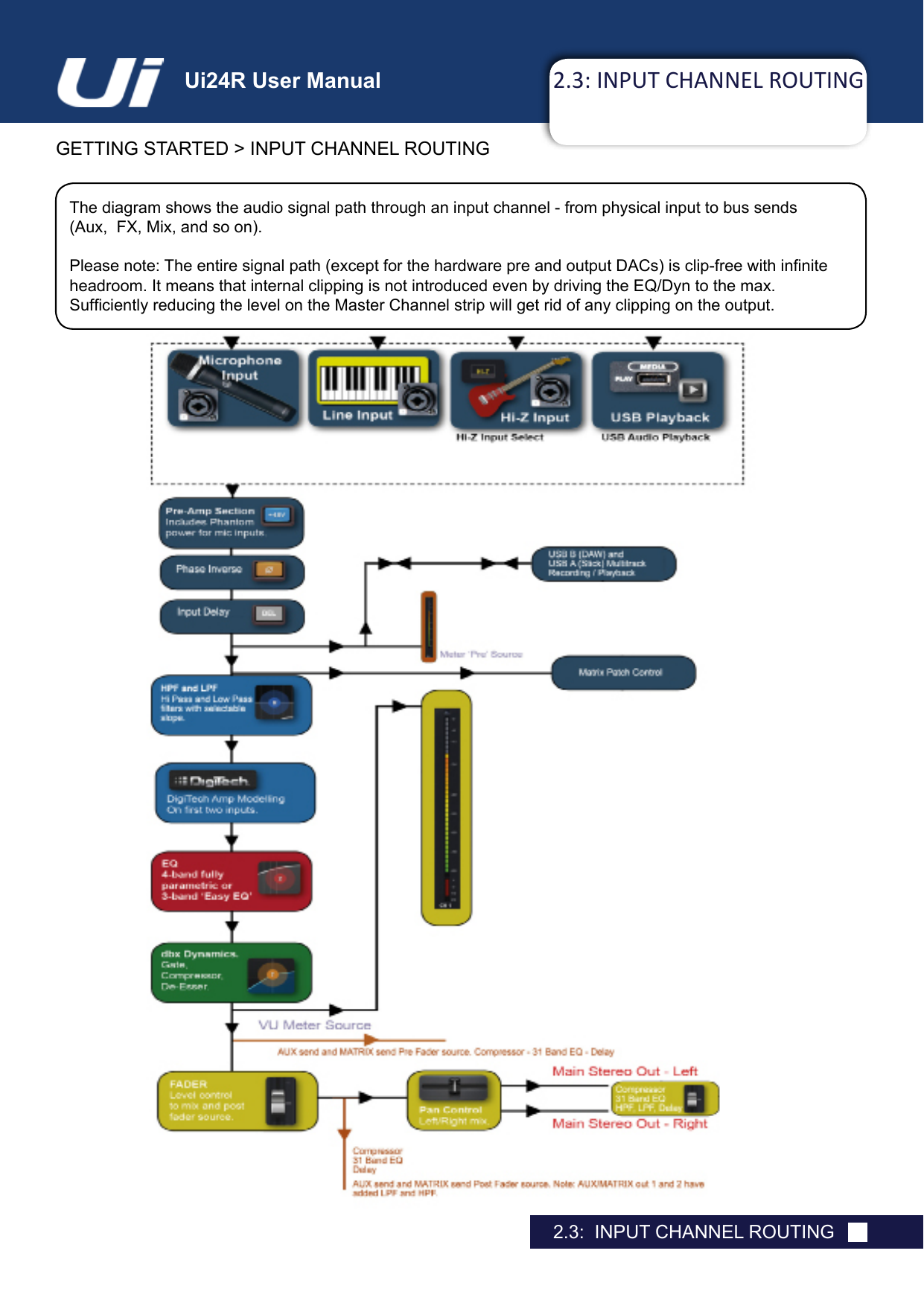
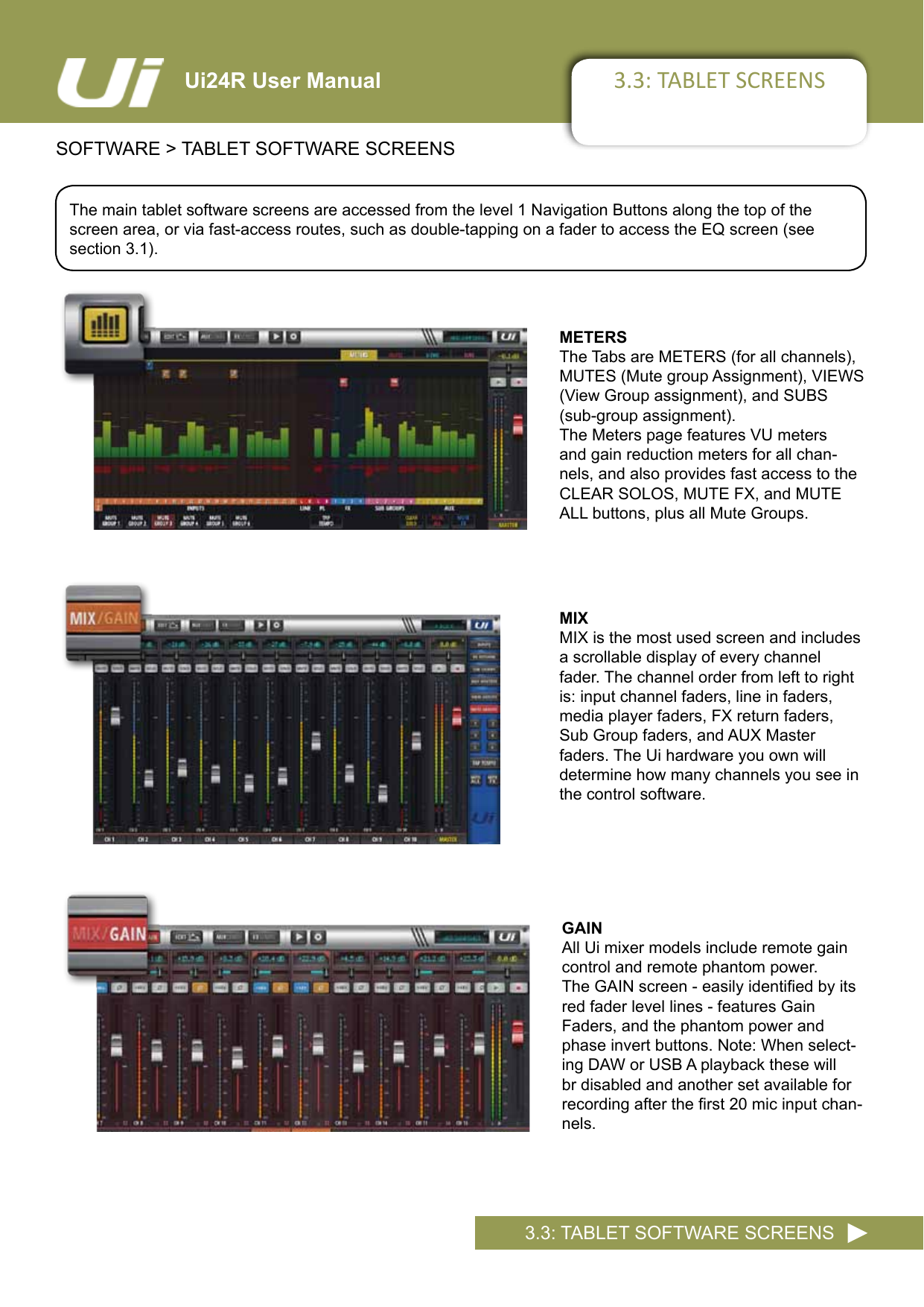
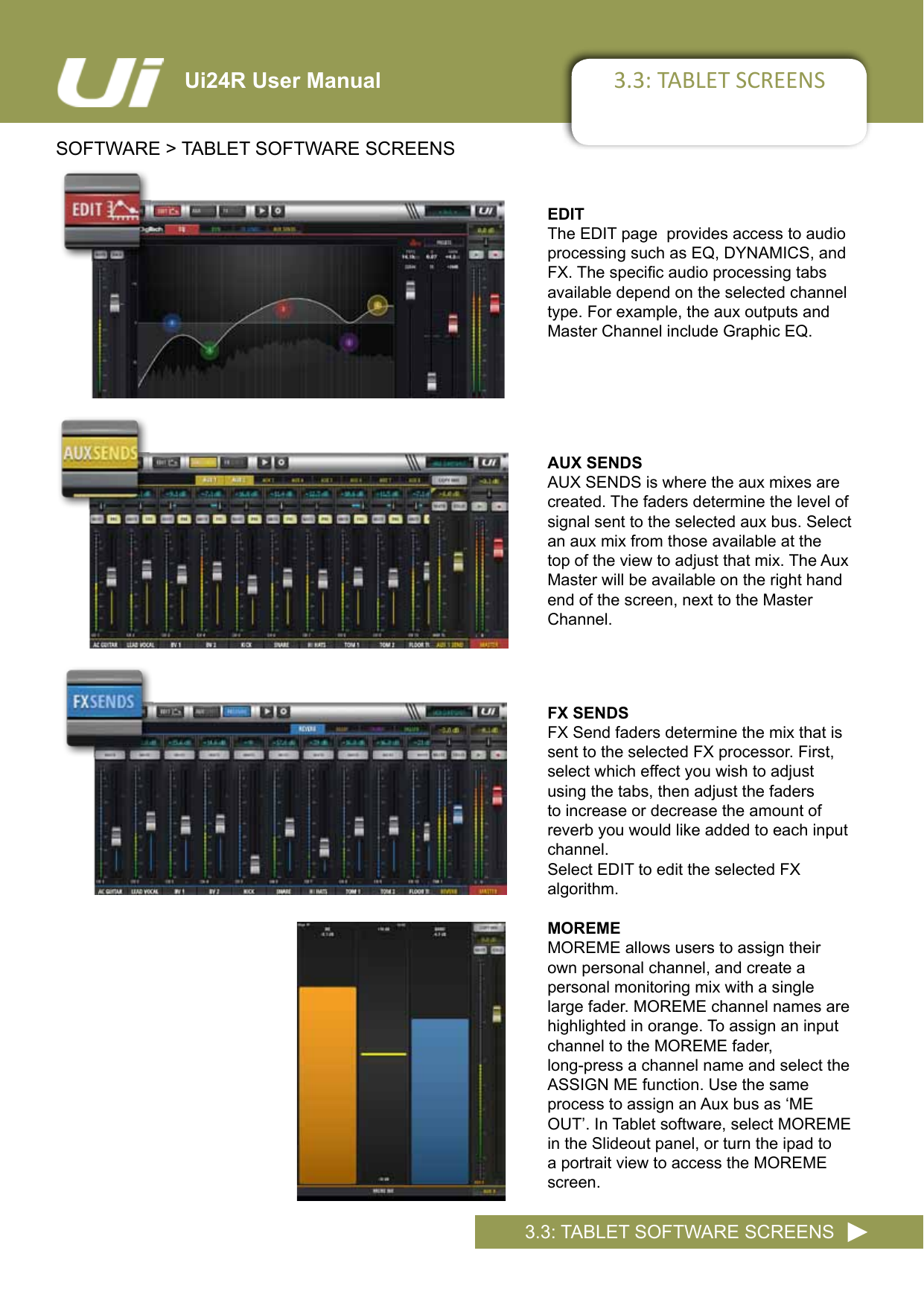
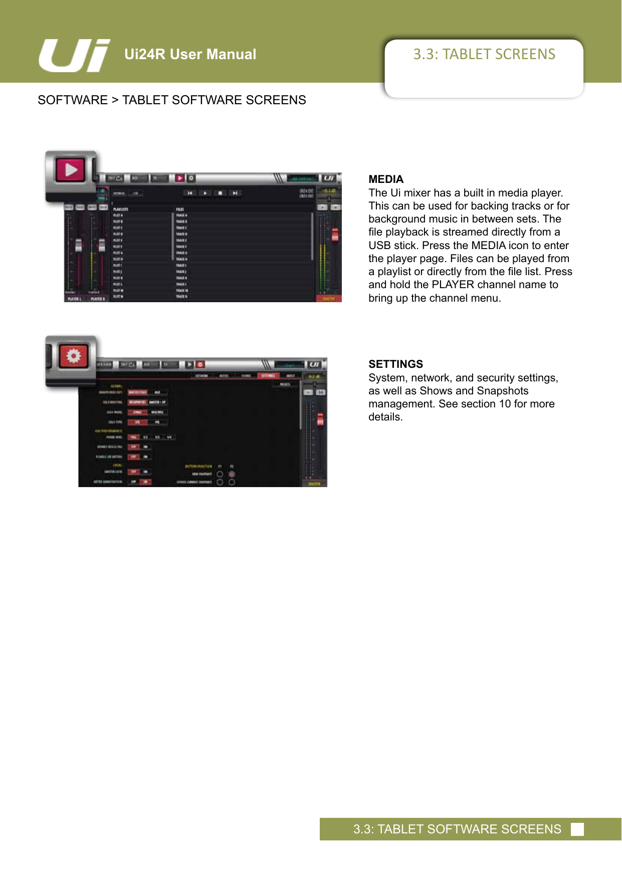
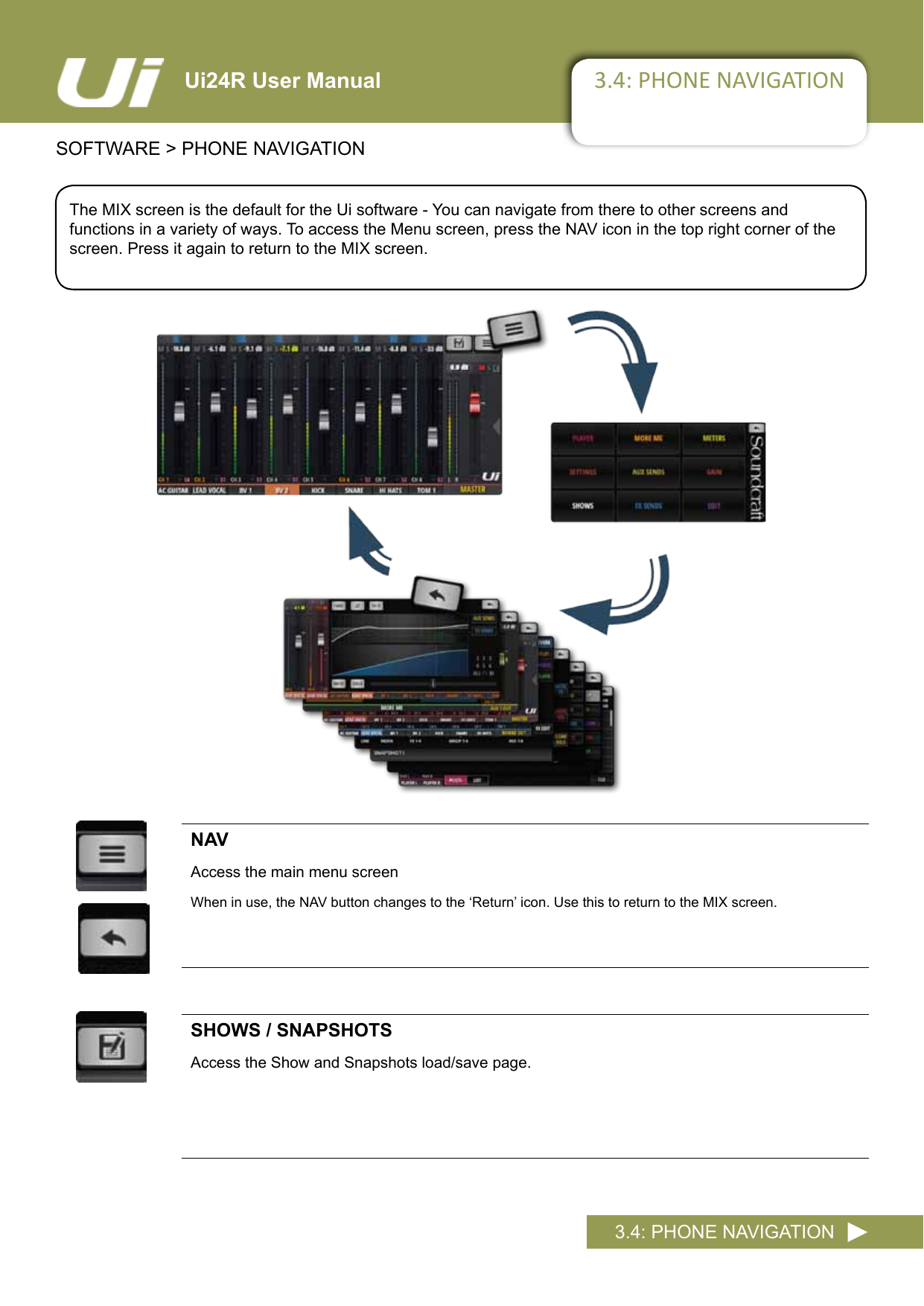
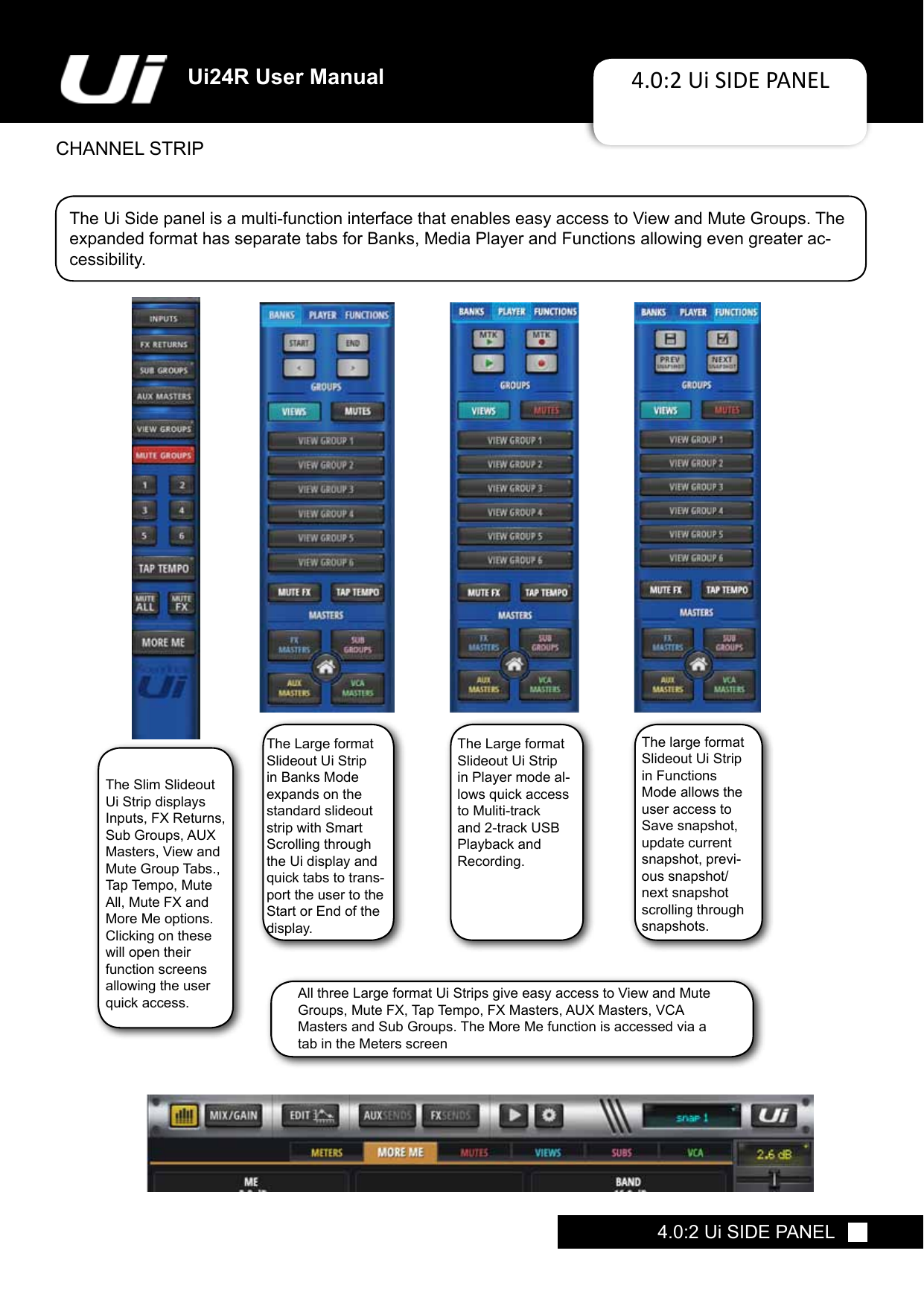
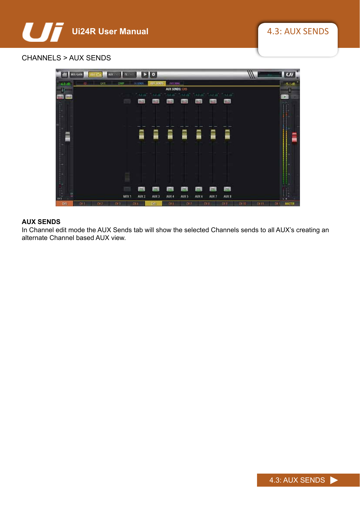
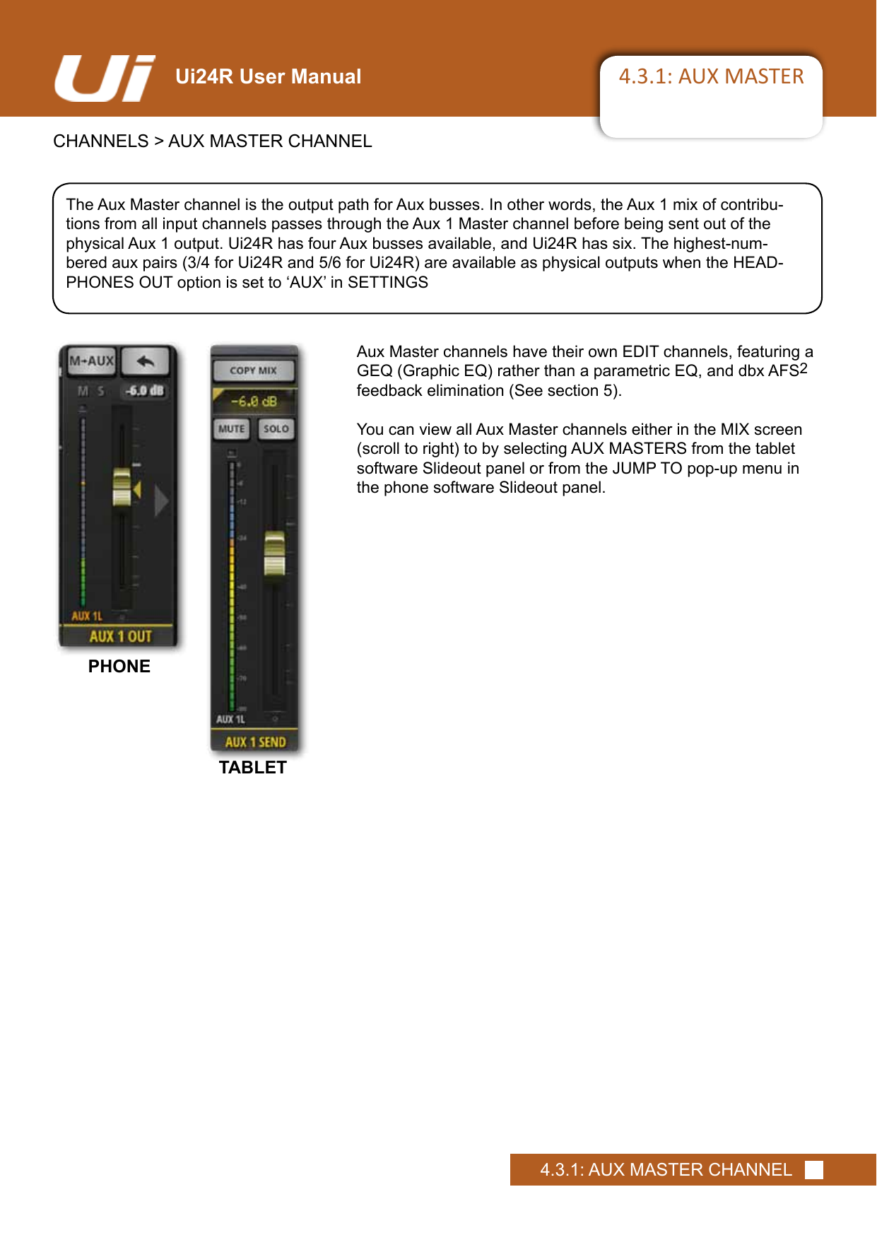
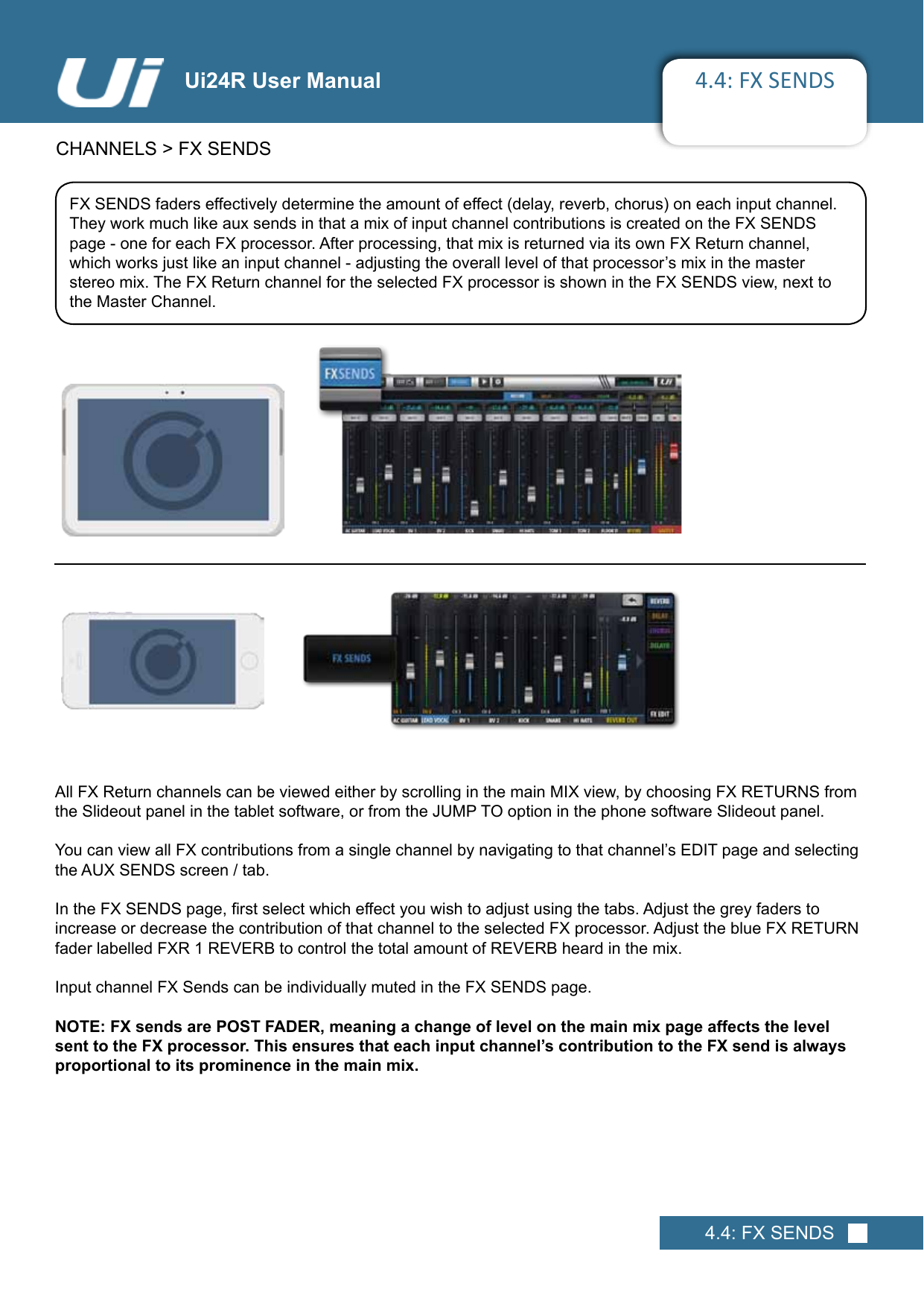
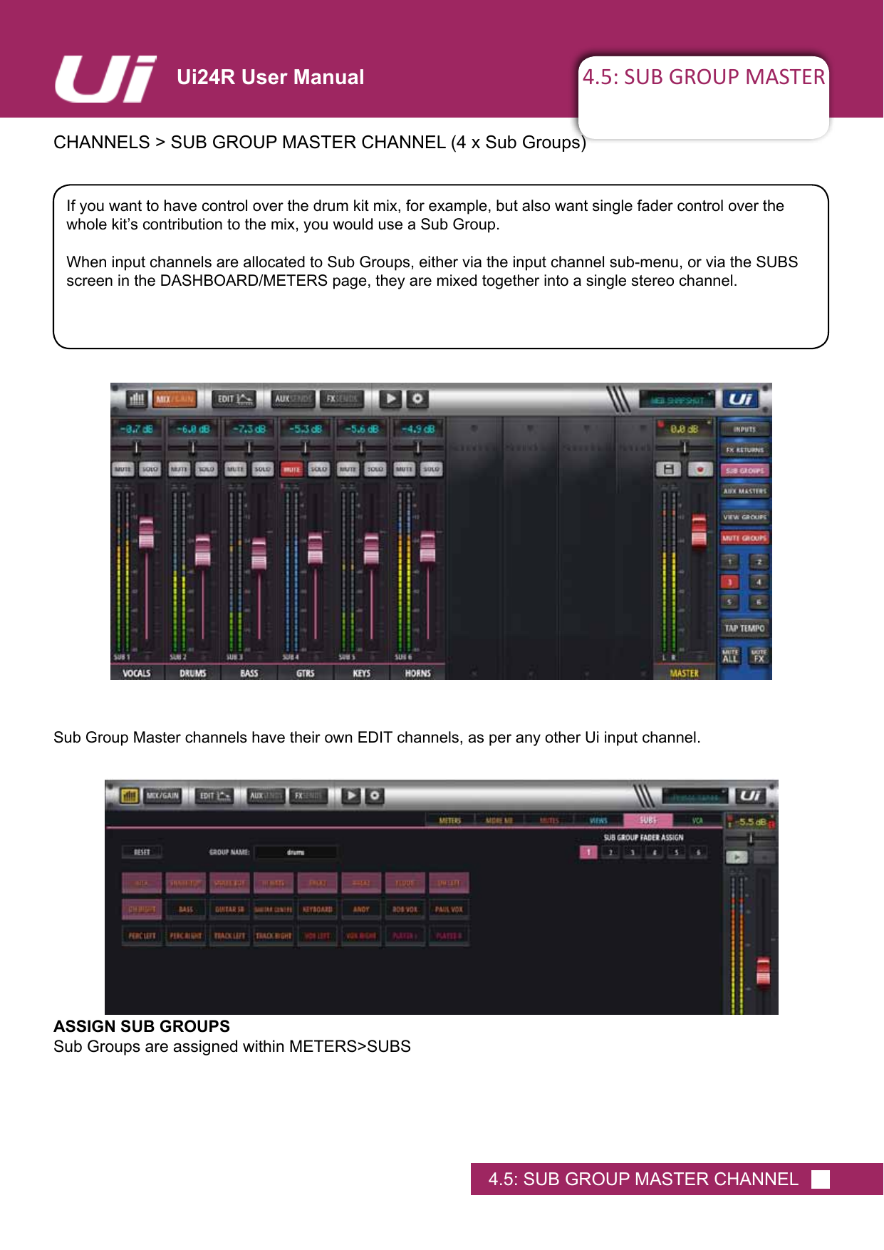
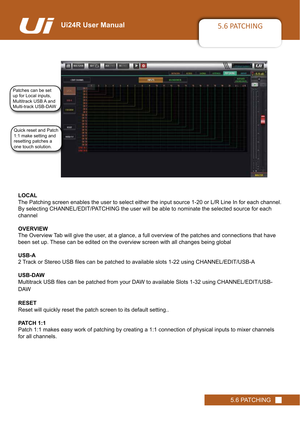
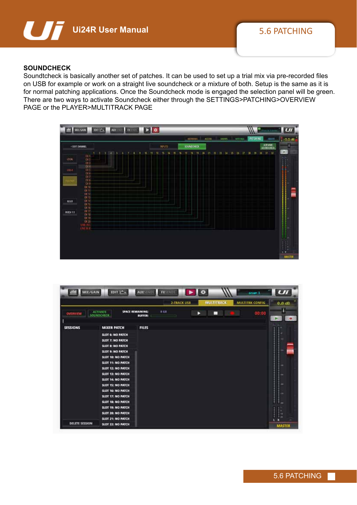
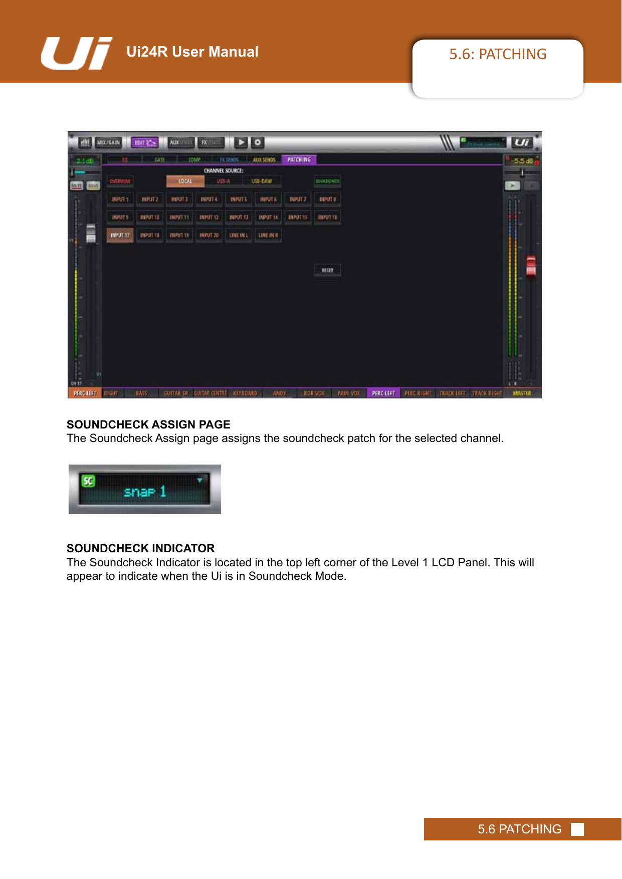
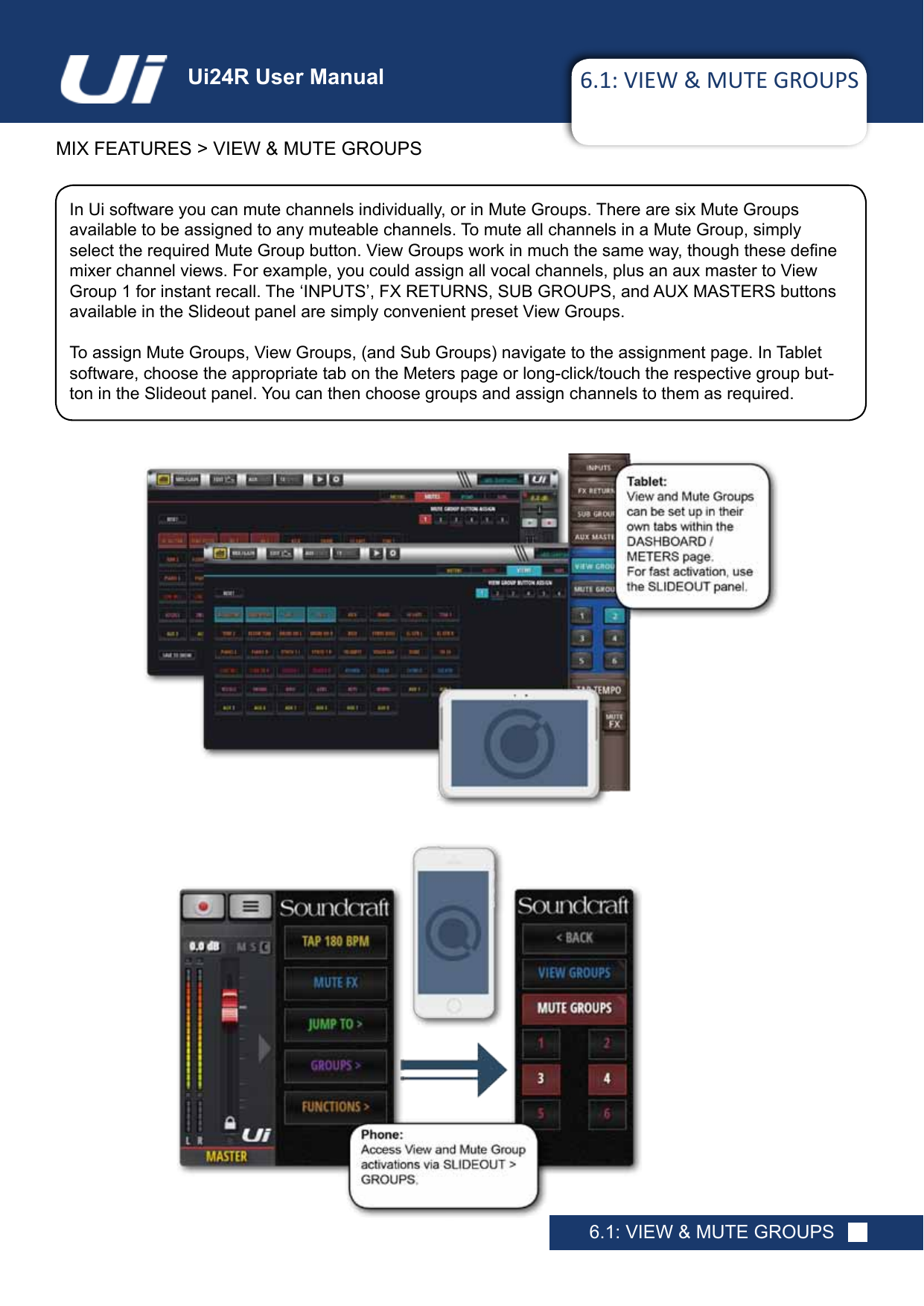
![Ui24R User Manual 8.0: SHOWS & SNAPSHOTSSHOWS & SNAPSHOTS8.0: SHOWS & SNAPSHOTSA SHOW is a collection of SNAPSHOTS. A SNAPSHOT is a record of every setting on the console. You can save and recall snapshots and shows via the Ui control software - Phone or Tablet.A snapshot remembers every setting of your mixer at one time. A common usage for snapshots is to have one snapshot per song. So your snapshot list could look exactly like your song list. At the end of each song, change to the next snapshot and every setting on the mixer is ready for that song to start. The SHOWS & SNAPSHOTS page is accessible in the tablet software from the SETTINGS page OR by tapping/clickingtheLEDdisplayinthetopnavigationbar(whichdisplaysthenameofthecurrentlyloadedsnapshot).Thequickkeytothesnapshotspop-upis[8].YoucanalsoassignanF1orF2key(topofMasterChannel)toupdatethecurrentsnapshotorcreateanewone.Inthephonesoftware,simplytapthedisk icon or assign the SlideOut F1 key to a snapshot function.](https://usermanual.wiki/Harman/UI24RMIXER/User-Guide-3356559-Page-95.png)