Harman UI24RMIXER 24 Channel Digital Mixer/Recorder User Manual
Harman International Industries, Inc 24 Channel Digital Mixer/Recorder
Harman >
User Manual
User Guide v1.1
For Soundcraft Ui24R
®
®
series
INFORMATION
INFORMATION
INFORMATION
IMPORTANT
Please read this manual carefully before using your mixer
for the rst time.
This equipment complies with the EMC directive 2004/30/EU and LVD 2014/35/EU
This product is approved to safety standards:
EN 60950-1:2006 + A11:2009 + A1:2010 + A12:2011 + A2:2013
And EMC standards
EN55032:2012+AC:2013
EN55103-2:2009
EN61000-3-3: 2013
EN61000-3-2: 2014
Warning: Any modication or changes made to this device, unless explicitly approved by Harman, will
invalidate the authorisation of this device. Operation of an unauthorised device is prohibited under Section
302 of the Communications act of 1934, as amended, and Subpart 1 of Part 2 of Chapter 47 of the Code of
Federal Regulations.
NOTE: This equipment has been tested and found to comply with the limits for a Class B digital device, pursuant to
Part 15 of the FCC Rules. These limits are designed to provide reasonable protection against harmful interference in
a residential installation. This equipment generates, uses and can radiate radio frequency energy and, if not installed
and used in accordance with the instructions, may cause harmful interference to radio communications. However,
there is no guarantee that interference will not occur in a particular installation. If this equipment does cause harmful
interference to radio or television reception, which can be determined by turning the equipment off and on, the user is
encouraged to try to correct the interference by one or more of the following measures:
* Reorient or relocate the receiving antenna
* Increase the separation between the equipment and the receiver
* Connect the equipment into an outlet on a circuit different from that to which the receiver is connected.
* Consult the dealer or an experienced radio/TV technician for help.
For further details contact:
Harman Professional Inc, 8500 Balboa Blvd. Northridge,CA 91329 USA
email: soundcraft@harman.com
© Harman International Industries Ltd. 2017 All rights reserved
Parts of the design of this product may be protected by worldwide patents.
Part No. 5076585 USA, 5076586 EU, 5085429 AU
Rev 1.0
E&OE January 2017
Soundcraft is a trading division of Harman International Industries Ltd. Information in this manual is subject to change
without notice and does not represent a commitment on the part of the vendor. Soundcraft shall not be liable for any
loss or damage whatsoever arising from the use of information or any error contained in this manual. No part of this
manual may be reproduced, stored in a retrieval system, or transmitted, in any form or by any means, electronic,
electrical, mechanical, optical, chemical, including photocopying and recording, for any purpose without the express
written permission of Soundcraft.
Harman International Industries Limited
8500 Balboa Blvd. Northridge,CA 91329 USA
http://www.soundcraft.com
Ui24R User Manual

CONTENTS
CONTENTS
CONTENTS
1.0 AN INTRODUCTION TO Ui
1.1: Safety
1.2: Warranty
1.3:Specications
2.0: GETTING STARTED
2.1: System Overview
2.2: Hardware I/O & Control
2.3: Input Channel Routing
2.4: Getting Connected
3.0: SOFTWARE CONTROL
3.0.1: Updates & Requirements
3.0.2: Reset The Mixer
3.1: Software Navigation
3.1.1: Control / Gesture Summary
3.2: Tablet Navigation
3.2.1: Keyboard Control
3.3: Tablet Screens
3.4: Phone Navigation
3.5: Phone Screens
4.0: MIXER CHANNELS
4.0.1: Channel Strip
4.0.2: Ui Side Panel
4.1: Input Gain Page
4.2: Input Mix Page
4.2.1: Input Sub Menu
4.2.2: VCA Groups
4.2.3: Matrix
4.2.4: Meters
4.3: Aux Sends
4.3.1: Aux Master
4.4: FX Sends
4.5: Sub Group Master
4.5.1: View/Mute Groups
4.6: Master Channel
4.6.1: Master Channel Sub-Menu
5.0: CHANNEL EDIT
5.1: DigiTech
5.2: Parametric EQ
5.3: Graphic EQ
5.3.1 AFS2 - Feedback Elimination
5.4:1: Gate
5.4.2: Compressor
5.5: Aux / FX Sends
5.6: Patching
6.0: MIX FEATURES
6.1: View & Mute Groups
6.2: MOREME
7.0: LEXICON FX EDIT
7.1: Reverb
7.2: Delay
7.3: Chorus
7.4: Effects Screen
8.0: SHOWS & SNAPSHOTS
9.0: MEDIA PLAYER & RECORDER
9.0.1: Multitrack Playback & Recording
9.0.2: USB Playback & Recording
10.0: SETTINGS
10.1:NetworkConguration
10.1.1: Hotspot Settings
10.1.2: Wi-Fi Settings
10.1.3: LAN Settings
10.1.4: Access control
APPENDIX 01: Troubleshooting: No Sound?
APPENDIX 02: Troubleshooting: System FAQ
For clarity, this manual uses section references rather than page numbers. In some instances, one section reference
may extend to several pages.
Ui24R User Manual
1.0: INTRODUCTION
INTRODUCTION TO Ui
1.0: INTRODUCTION TO Ui
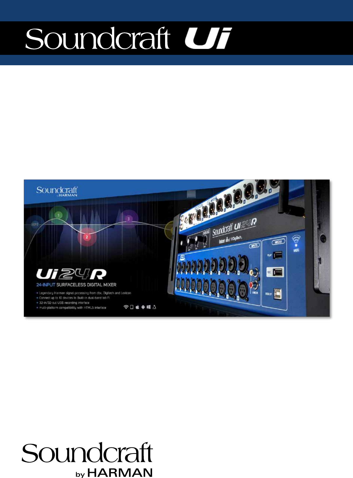
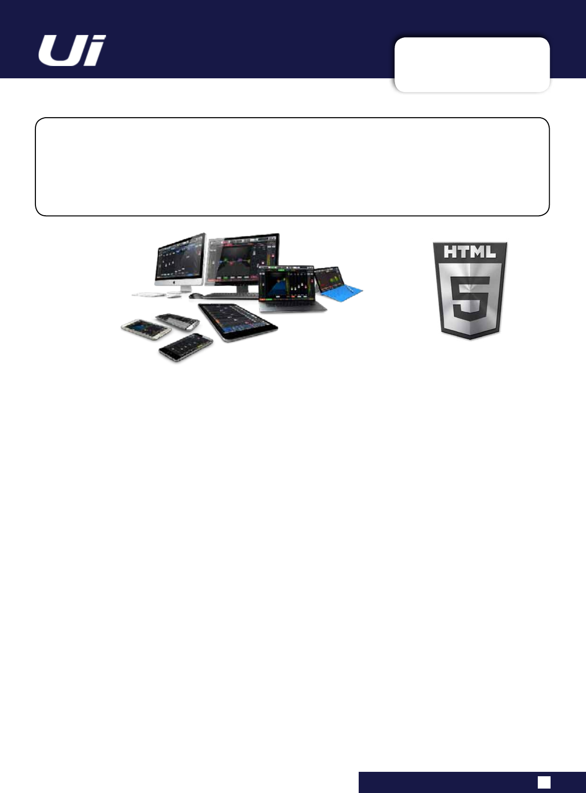
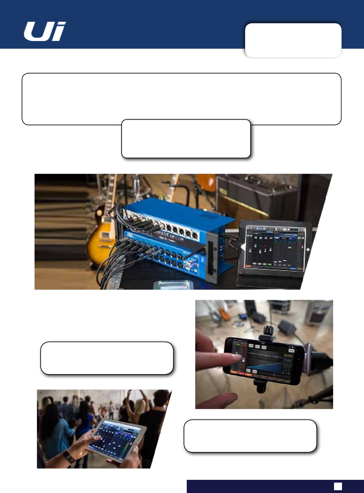
The Ui Series mixers feature cross-platform compatibility with iOS, Android, Windows, Mac OS, and
Linux devices, and can use up to 10 control devices simultaneously. In addition, the Ui24R features
built-in HARMAN signal processing from dbx, DigiTech and Lexicon, including dbx AFS2, DigiTech
Amp Modeling, and more. The Ui24R features fully recallable and remote-controlled mic pre-amps and
phantom power designed by Studer.
MAIN FEATURES
•Tablet/PC/SmartphoneControlledDigitalMixer
•IntegratedDualAntenna2.4Gand5GWi-FiandLANconnection
•Cross-platformcompatibilitywithiOS,Android,Windows,MacOS,andLinuxdevices
•Useupto10controldevices(tablets,phones,PCs)simultaneously
•LegendaryHarmanSignalProcessingfromdbx®,Digitech®,andLexicon®
•Fullyrecallableandremote-controlledmicpreamps
•4-bandParametricEQ,High-PassFilte,Low-PassFilerr,Compressor,De-esserandNoiseGateoninputchannels
•31-bandGraphicEQ,NoiseGateandCompressoronalloutputs(MasterL/RandAUX1/2featureLPFancdHPFlters)
•Real-TimeFrequencyAnalyser(RTA)oninputsandoutputs
•4dedicatedLexicon®FXeffectsprocessors:Reverbs,Delays,Chorus
•4xSubgroups,6xVCA’s,MuteGroups,ViewGroups,andMOREMEmixercontrols
•Show/Snapshotrecallwithchannelsafesandsecuritylockout
•2-channelUSBaudioplaybackandrecordingand22multi-trackUSBrecording
•32x32USBAudioInterface
•IntergratedswitchmodeIECconnectionpowersupply
Ui24R User Manual
The Ui24R boasts 22 mic/line inputs, 10 x XLR combo mic/line inputs, 10 x XLR mic inputs, two channels of
Hi-Z/instrument inputs, as well as a stereo RCA line input. A 2-channel USB media player is included, along
with eight balanced XLR Aux/Matrix outputs, two quarter-inch headphone outputs with level control, plus
balanced stereo XLR and quarter-inch main outputs. Two-channel USB audio playback is compatible with
MP3, WAV and AIFF formats. It also includes a 22 multi-track recorder/player, 32 x 32 low latency audio
interface and direct HDMI display connection output.
1.1: SAFETY
INTRODUCTION > SAFETY
1.1: INTRODUCTION > SAFETY
The internal power supply unit contains no user serviceable parts. Refer all servicing to a qualied service
engineer, through the appropriate Soundcraft dealer.
Radio frequency exposure
This equipment complies with FCC radiation exposure limits set forth for an uncontrolled environment. End users must
followthespecicoperatinginstructionsforsatisfyingRFexposurecompliance.Thistransmittermustnotbeco-locat-
edoroperatinginconjunctionwithanyotherantennaortransmitter.NomodicationsChangesormodicationsnot
expresslyapprovedbythepartyresponsibleforcompliancecouldvoidtheuser’sauthoritytooperatetheequipment.
The minimum distance required away from the Ui24R mixer and or any antenna is 20cm.
Canada Statement
ThisdevicecomplieswithIndustryCanada’slicence-exemptRSSs.Operationissubjecttothefollowingtwocondi-
tions:
(1)Thisdevicemaynotcauseinterference;and
(2)Thisdevicemustacceptanyinterference,includinginterferencethatmaycauseundesiredoperationofthedevice.
LeprésentappareilestconformeauxCNRd’IndustrieCanadaapplicablesauxappareilsradioexemptsdelicence.
L’exploitationestautoriséeauxdeuxconditionssuivantes:
(1)l’appareilnedoitpasproduiredebrouillage;
(2)l’utilisateurdel’appareildoitacceptertoutbrouillageradioélectriquesubi,mêmesilebrouillageestsusceptible
d’encompromettrelefonctionnement.
This End equipment should be installed and operated with a minimum distance of 20 centimeters between the radiator
and your body.
Cetéquipementdevraitêtreinstalléetactionnéavecunedistanceminimumde20centimètresentreleradiateuret
votre corps.
SAFETY NOTICES
For your own safety and to avoid invalidation of the warranty
please read this section carefully.
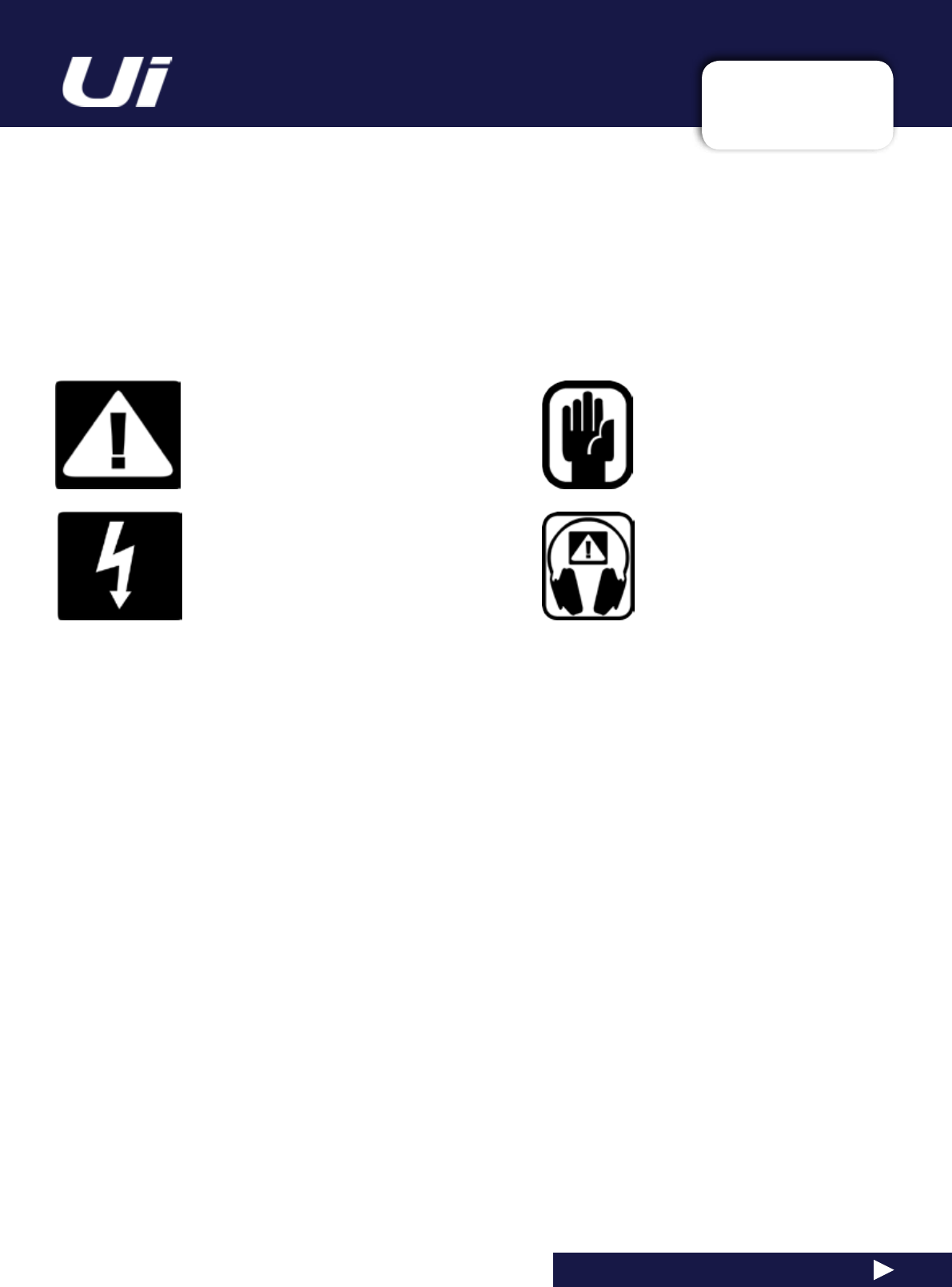
Important Symbols
Warnings
Alerts the user to the presence of uninsulated
‘dangerousvoltage’withintheproduct’s
enclosurethatmaybeofsufcientmagnitude
to constitute a risk of electric shock to persons.
Cautions
Alerts the user to the presence of important
operatingandmaintenance(servicing)
instructions in the literature accompanying
the appliance.
Ui24R User Manual

1.1: SAFETY
INTRODUCTION > SAFETY
1.1: INTRODUCTION > SAFETY
WARNINGS
•Read these instructions.
•Keep these instructions.
•Heed all warnings.
•Follow all instructions.
•Clean the apparatus only with a dry cloth.
•Do not install near any heat sources such as radiators, heat resistors, stoves, or other apparatus
(includingampliers)thatproduceheat.
•Do notblockanyventilationopenings.Installinaccordancewiththemanufacturer’sinstructions.
•Do not use this apparatus near water.
•Do not defeat the safety purpose of the polarized or grounding type plug. A polarized plug has two
blades with one wider than the other. A grounding type plug has two blades and a third grounding
prong. The wide blade or the third prong are provided for your safety. When the provided plug does not
tintoyouroutlet,consultanelectricianforreplacementoftheobsoleteoutlet.
•Protect the power cord from being walked on or pinched particularly at plugs, convenience
receptacles and the point where they exit from the apparatus.
•Onlyuseattachments/accessoriesspeciedbythemanufacturer.
•Unplug this apparatus during lightning storms or when unused for long periods of time.
•Referallservicingtoqualiedservicepersonnel.Servicingisrequiredwhentheapparatushasbeen
damaged in any way such as power-supply cord or plug is damaged, liquid has been spilled or objects
have fallen into the apparatus, the apparatus has been exposed to rain or moisture, does not operate
normally, or has been dropped.
•Useonlywiththecart,stand,tripod,bracket,ortablespeciedbythemanufacturer,orsoldwiththe
apparatus. When the cart is used, use caution when moving the cart/apparatus combination to avoid
injury from tip-over.
•Nonakedamesources,suchaslightedcandlesorcigarettesetc.,shouldbeplacedonthe
apparatus.
•No user serviceable parts.Referallservicingtoaqualiedserviceengineer,throughthe
appropriate Soundcraft dealer.
•The socket-outlet shall be installed near the equipment and shall be easily accessible.
• It is recommended that all maintenance and service on the product should be
carried out by Soundcraft or its authorised agents. Soundcraft cannot accept any
liability whatsoever for any loss or damage caused by service, maintenance or repair
by unauthorised personnel.
• WARNING: To reduce the risk of re or electric shock, do not expose this
apparatus to rain or moisture. Do not expose the apparatus to dripping or splashing
and do not place objects lled with liquids, such as vases, on the apparatus. No
naked ame sources, such as lighted candles, should be placed on the apparatus.
• Ventilation should not be impeded by covering the ventilation openings with items
such as newspapers, table cloths, curtains etc or mounting in enclosures where ari
cannot circulate to an appropriate level to keep the Ui24R under 40C or 104F.
Ui24R User Manual
1.1: SAFETY
INTRODUCTION > SAFETY
1.1: INTRODUCTION > SAFETY
WARNINGS
ADVICE FOR THOSE WHO PUSH THE BOUNDARIES
Although your new console will not output any sound until you feed it signals, it has the capability
toproducesoundswhich,whenmonitoredthroughanamplierorheadphones,candamagehear-
ing over time.
Pleasetakecarewhenworkingwithyouraudio—ifyouaremanipulatingcontrolswhichyoudon’t
understand(whichwealldowhenwearelearning),makesureyourmonitorsareturneddown.Rememberthat
your ears are the most important tool of your trade, look after them, and they will look after you.
Mostimportantly—don’tbeafraidtoexperimenttondouthoweachparameteraffectsthesound—thiswill
extend your creativity and help.
NOTE: The packaging, in which your console arrived, forms part of the product and must be retained
for future use.
NOTE: This equipment has been tested and found to comply with the limits for a Class B digital de-
vice, pursuant to Part 15 of the FCC Rules. These limits are designed to provide reasonable protec-
tion against harmful interference when the equipment is operated in a commercial environment. This
equipment generates, uses and can radiate radio frequency energy and, if not installed and used in
accordance with the instruction manual, may cause harmful interference to radio communications.
Operation of this equipment in a residential area is likely to cause harmful interference in which
case the user will be required to correct the interference at his own expense.
This Class B digital apparatus meets the requirements of the Canadian Interference-Causing
Equipment Regulations.
CetappareilnumériquedelaClasseBrespectetouteslesexigencesduRèglementsurlematérielbrouilleurdu
Canada.
Ui24R User Manual
This device for operation in the band 5150–5250 MHz is only for indoor use to reduce the potential for harmful
interference to co-channel mobile satellite systems.
The maximum antenna gain permitted for this device in the band 5725-5850 MHz complies with the e.i.r.p.
limits specied for non-point-to-point operation.
This radio transmitter (IC: 6132A-UI24RMIXER) has been approved by Industry Canada to operate with the
antenna types listed below with the maximum permissible gain indicated. Antenna types not included in this
list, having a gain greater than the maximum gain indicated for that type, are strictly prohibited for use with
this device.
Antenna used by this product:
(SMA-2.4/5.8G-178-L108MM) ; peak gain 3.74dBi

1.2: WARRANTY
INTRODUCTION > SAFETY
1.2: INTRODUCTION > WARRANTY
WARRANTY
1 Soundcraft is a trading division of Harman International Industries Ltd.
EndUsermeansthepersonwhorstputstheequipmentintoregularoperation.
DealermeansthepersonotherthanSoundcraft(ifany)fromwhomtheEndUserpurchasedtheEquipment,
provided such a person is authorised for this purpose by Soundcraft or its accredited Distributor.
Equipment means the equipment supplied with this manual.
2 If within the period of twelve months from the date of delivery of the Equipment to the End User it shall prove
defective by reason only of faulty materials and/or workmanship to such an extent that the effectiveness and/or
usability thereof is materially affected the Equipment or the defective component should be returned to the
Dealer or to Soundcraft and subject to the following conditions the Dealer or Soundcraft will repair or replace
the defective components. Any components replaced will become the property of Soundcraft.
3AnyEquipmentorcomponentreturnedwillbeattheriskoftheEndUserwhilstintransit(bothtoandfromthe
DealerorSoundcraft)andpostagemustbeprepaid.
4 This warranty shall only be available if:
a)TheEquipmenthasbeenproperlyinstalledinaccordancewithinstructionscontainedinSoundcraft’smanual.
b)TheEndUserhasnotiedSoundcraftortheDealerwithin14daysofthedefectappearing;and
c)NopersonsotherthanauthorisedrepresentativesofSoundcraftortheDealerhaveeffectedanyreplacement
ofpartsmaintenanceadjustmentsorrepairstotheEquipment;and
d)TheEndUserhasusedtheEquipmentonlyforsuchpurposesasSoundcraftrecommends,withonlysuch
operatingsuppliesasmeetSoundcraft’sspecicationsandotherwiseinallrespectsinaccordanceSoundcraft’s
recommendations.
5 Defects arising as a result of the following are not covered by this Warranty: faulty or negligent handling, chemi
calorelectro-chemicalorelectricalinuences,accidentaldamage,ActsofGod,neglect,deciencyinelectrical
power, air-conditioning or humidity control.
6.ThebenetofthisWarrantymaynotbeassignedbytheEndUser.
7. End Users who are consumers should note their rights under this Warranty are in addition to and do not affect
any other rights to which they may be entitled against the seller of the Equipment.
Ui24R User Manual

1.3: SPECIFICATIONS
INTRODUCTION > SAFETY
1.3: SPECIFICATIONS
Ui24R User Manual
SOUNDCRAFT Ui TYPICAL SPECIFICATIONS
• Frequency Response
20Hz-20kHz +/- 0.5 dB
• THD
Micinput(Mingaintobus)@1kHz<0.005%
Micinput(Maxgaintobus)@1kHz<0.008%
• Noise
Residual Noise -96dBu
Mic Input E.I.N.22Hz-22kHz unweighted:
-128dB EIN
• Input Gain
Mic/LineGain-6dBto+58dB(Stepaccuracy
dependsonsizeoffaderinGUI)
• Gate
Threshold -inf to +6dB
Attack 1ms to 400ms
Release 5ms to 2000ms
Hold 1ms to 2000ms
Depth -inf to 0dB
• Compressor
Threshold -90dB +6dB
Ratio 1:1 - 50:1
Attack 1ms - 400ms
Release 10ms - 2000ms
Makeup Gain -24dB - +48dB
• EQ Channel
4 band parametriq EQ
Each Band Freq 20Hz to 22kHz
Q .05 - 15
Gain -20dB to +20dB
HPF20Hzto1kHz(selectableslopes)
LPF22kHzto1kHz(selectableslopes)
• De-esser
Threshold -90dB to 6dB
Ratioinnityto1:1
Frequency 2kHz to 15kHz
• EQ Outputs
31 band GEQ, 20Hz - 20KHz +-15dB
• Compressor outputs
Threshold -90dB +6dB
Ratio 1:1 - 50:1
Attack 1ms - 400ms
Release 10ms - 2000ms
Makeup Gain -24dB - +48dB
• dbx® AFS on all outputs
12parametricEQ’s(6xed,6oating)
• Latency
All Processing ON for inputs and outputs 3.2ms
• Input and Output Levels
Mic Input +19.5dBu max
Line input +19.5dBu max
Mix output +20.5dBu max
Headphone outputs 500mW 1 output used
(@120Ω),380mwbothoutputsused
• Input and Output Impedances
Micinput1-24.2kΩinput3-206kΩ
LineInput12kΩ
Hi-ZInput>600kΩ
BalancedOutputs<150Ω
• USB
Max Current 500mA
Max Current available to all ports: 900mA
• Power
Consumption(typical)<65W
AC input voltage range 88-265VAC auto sensing
AC frequency 47-63Hz
• Operating Conditions
Temperature range 5°C - 40°C
Humidity0%-90%
Storage Temperature -20°C to 60°C
E & OE.Soundcraft reserves the right to change
specicationsandorimagesinthismanualwith-
out notice.
Ui24R User Manual 2.0: GETTING STARTED
GETTING STARTED - AN INTRODUCTION TO THIS MANUAL
2.0: INTRODUCTION TO THIS MANUAL
Anyone with minimal audio experience should be able to operate the Soundcraft Ui Series consoles
without reading too much of this manual, though we do recommend you take the time to go through it.
Anexcellentplacetostartwouldbethefeaturelistontheintroductorypage(section1.0),theWi-Fi
andsoftwareset-upguide(3.1),andthesoftwarecontrolguidesforphone(3.2)andtablet(3.3)soft-
ware.
PDF
Ifyou’rereadingthePDFversionofthemanual,
you can use the thumbnail view and links from
the Contents page to navigate quickly.
For clarity, this manual uses section references
rather than page numbers. In some instances,
one section reference may extend to several
pages.
To get started with Ui control,
go to the ‘Getting Connected’
section: 2.4
2.1: SYSTEM OVERVIEW
GETTING STARTED > SYSTEM OVERVIEW
2.1: SYSTEM OVERVIEW
This Soundcraft Ui console uses a compact main unit with built-in I/O, processing, and web server. Phones,
tablets, and PCs can connect to the web server via Wi-Fi for platform-independant software control.
Ui24R User Manual
NOTE: When mouting the Ui24R in any kind of enclosure make sure you
have sufcient space above, bellow and on bothsides of the Ui24R for pas-
sive cooling of the device. In exterme environments a fan may need to be
added to your enclosure!
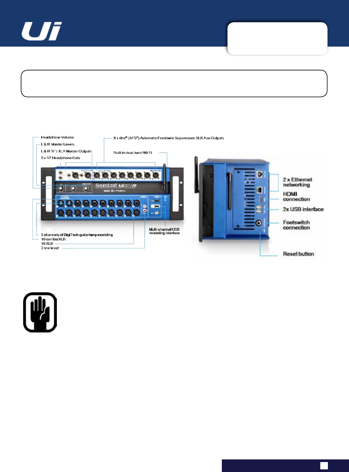
2.2: HARDWARE I/O & CONTROL
GETTING STARTED > HARDWARE
2.2: Hardware I/O And Control
TheUimainunit’sfrontpanelhostsalllocalaudioinputsandoutputsplusthreemasterlevelcontrols.
Ononesidepanelyouwillndthepowerconnectorandpowerswitch;ontheotheryouwillndthe
RESETbutton,FOOTSWITCHconnection,twoUSBports,andtheEthernet(wiredLAN)connection).
COMBO INPUT
Connectionfor1/4”TRS/TSJack(Line)orXLR(Miclevel)
The input number corresponds to channel number in the Ui control software.
XLR Input
Mic XLR Input
The input number corresponds to channel number in the Ui control software.
Ui24R User Manual
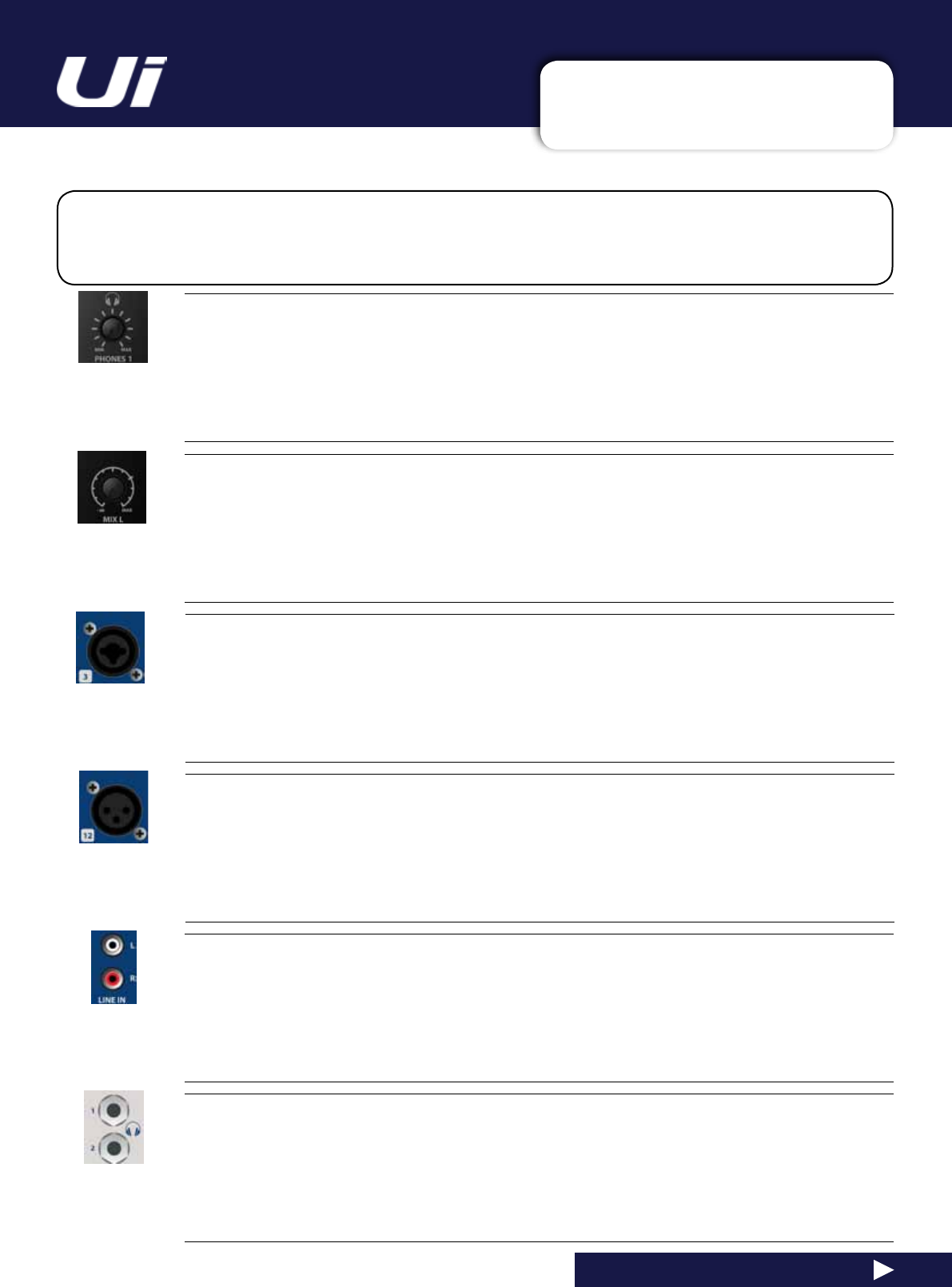
PHONES
Set level for headphones outputs
This controls the overall level of headphone output one. Individual headphone volume control can be
achieved through the SETTINGS control page. The headphone source signal defaults to the main stereo
signal but switches to the Solo bus when AFL or PFL is selected.
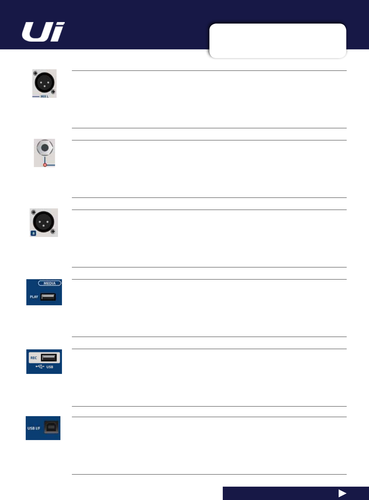
MIX L / MIX R
Set levels for MIX L and Mix R outputs
TheMixoutputistheUi’smainleft/rightstereooutputandappearsonboththeXLRandJackMixL/Rout-
puts.
LINE IN
Line level RCA inputs
The RCA inputs feed the Line In L and Line In R channels in the UI mixer.
HEADPHONES OUT
Headphone sockets
These are not independent, meaning each output receives the same signal. The headphone outputs receive
the same audio signal as the main outputs unless a channel Solo is active note the volumes can be inde-
pendently controlled in the SETTINGS page as well as the SOLO level.
2.2: HARDWARE I/O & CONTROL
GETTING STARTED > HARDWARE
2.2: Hardware I/O And Control
MIX L/R OUTPUT - JACK
Master Channel Jack outputs
TheMasterChannelXLRandjackoutputsareparallelconnections(identical).
AUX/MATRIX OUTPUTS
Physical outputs for the Aux/Matrix outputs
The Ui24R has 8 x Aux/Matrix outputs. Aux/Matrix outputs are assigned in software.
2 TRK MEDIA - PLAY
USBSocketforUSBFlashDrivewithaudioplaybackles
2trackAudiolesmustbesavedtotheUSBstickaseitherMP3,AAC,.WAV,.OGG,.AIFF,or.FLACles.
See section 9.0.
This USB socket can also be used for Show File and Snaphot import/export, and software updates. There
are two additional USB sockets on the side of the unit.
Ui24R User Manual
MIX L/R OUTPUT - XLR
Master Channel XLR outputs
TheMasterChannelXLRandjackoutputsareparallelconnections(identical).
MEDIA - REC plus Multi-track Play and Record
USB Socket for USB Flash Drive - for multi-track play and record audio
TheSoundcraftUi24RRmixerwillrecordtheMasterChannelstereooutputasastereoleormultitrack
recording onto the storage device. See guide for playback and recording instructions - section 9.0.
USB B (DAW Connection)
USB Socket for connection directly to PC/Mac
The Soundcraft Ui24RR mixer can be used as a 32 x 32 USB Audio Interface with CORE Audio and ASIO
drivers.
2.2: HARDWARE I/O & CONTROL
GETTING STARTED > HARDWARE
2.2: Hardware I/O And Control
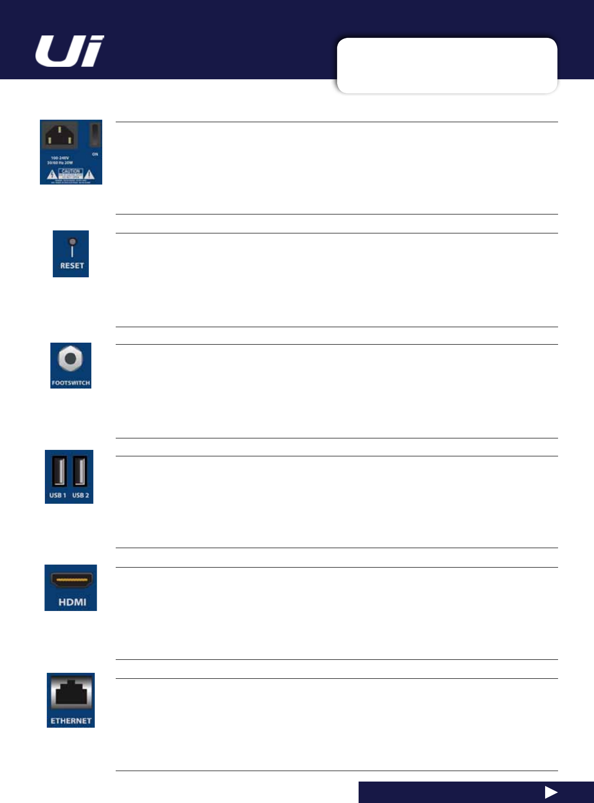
RESET
Recessed push switch used to reset the unit.
To reset Network settings ONLY, switch the unit on while holding down the reset button for at least ten sec-
onds. For a full system reset, see section 3.0.2.
FOOTSWITCH
Footswtichconnectorusedtotoggleselectedcongurations.
Use a footswitch with a quarter-inch jack connection. The unit will auto-detect the connector type, though
the footswitch itself must be a non-latching type. The SETTINGS page has a variety of functions that can be
assigned.
Side USB Connectors 1 & 2
May be used for Connecting Keyboard, Mouse and Touchscreen
There are USB connections on the front panel of the unit for audio recording and playback.
ETHERNET
Standard RJ45-wired connector for use with wired Ethernet.
A wired Ethernet conenction to the Ui is the most secure. See section 10.1 for more details on network set-
tingsandcongurations.BydefaulttheIPaddressis10.10.2.1.
HDMI Connector
Supports HDMI Video standard
Complete Mixer Web Interface is displayed on HDMI screen. Please note if using DVI and VGA adaptors
they must be active. Performance will depend on other concurrent functions which are being used in the
mixer.(eg.whilerecordingtoUSBMTKstickyoumayseeaslowdowninscreenupdate)
Ui24R User Manual
PWR
Power Connector & Switch
The Ui mixer has an AC IC connection universal power supply. Use the power switch with the reset button
(othersidepanel)toresettheunittofactorydefaultsettingsifrequired.
2.2: HARDWARE I/O & CONTROL
GETTING STARTED > HARDWARE
2.2: Hardware I/O And Control
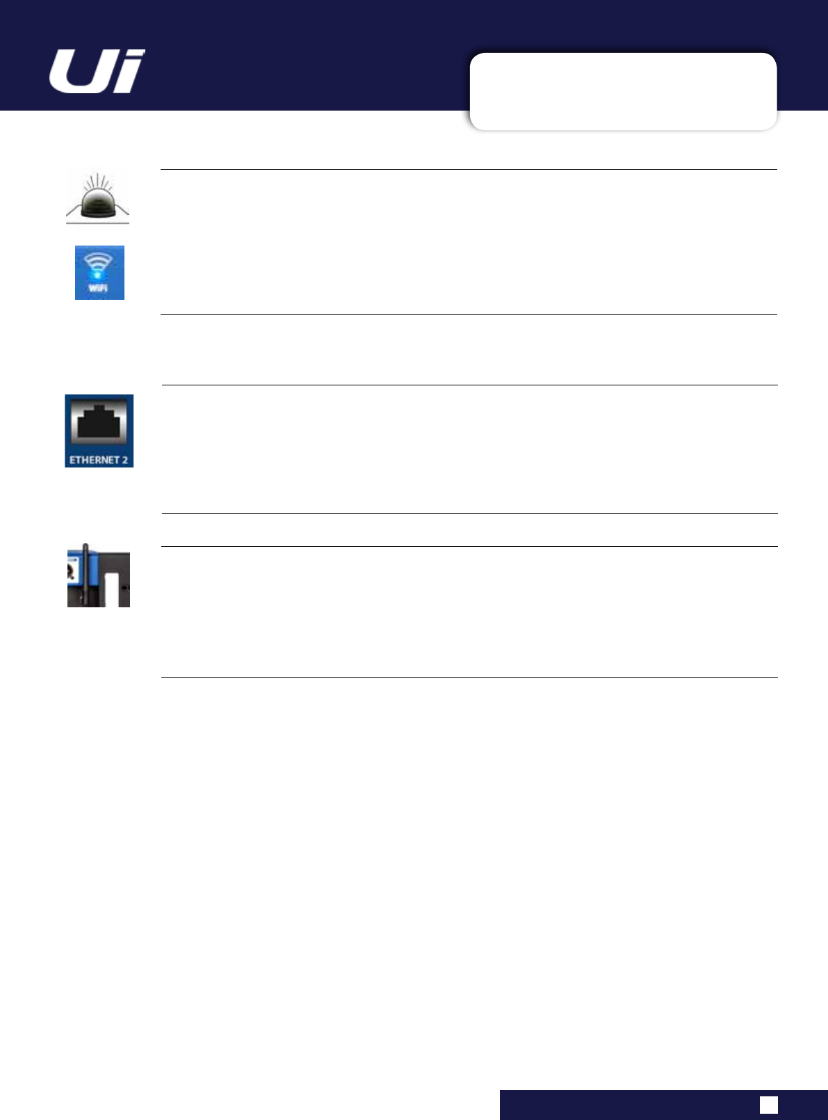
Wi-Fi Indicator
Shows Wi-Fi is operating normally
TheindicatoralsoshowsWi-Fibootstatusduringpowerup.Itstopsitstimedashsequencewhenbooted
andavailableforconnections.Thenasheswithdataactivity.
IftheWiFiLEDkeepsashingitcanmeanthermwareisnotloadingintotheDSP.Makesurelatestrm-
ware is loaded into the unit and that the DC power connector is properly screwed on.
Ui24R User Manual
ETHERNET 2
Future Expansion Port
Wi-Fi Antenna
Necessary for wireless network connection - Hotspot or WiFi
MakesuretheAntenna(s)arermlyscrewedintotheirsocketsandnormallyorientatedvertically.Formore
informationonwirelessnetworksettings,seesection10.1.TheUi24RRshipswith2WiFiantenna’sforbet-
terwiperformance.ThesecondantennaisontherightsideoftheUi24R.
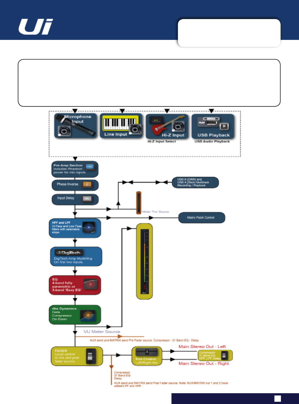
2.3: INPUT CHANNEL ROUTING
GETTING STARTED > INPUT CHANNEL ROUTING
2.3: INPUT CHANNEL ROUTING
The diagram shows the audio signal path through an input channel - from physical input to bus sends
(Aux,FX,Mix,andsoon).
Pleasenote:Theentiresignalpath(exceptforthehardwarepreandoutputDACs)isclip-freewithinnite
headroom. It means that internal clipping is not introduced even by driving the EQ/Dyn to the max.
SufcientlyreducingthelevelontheMasterChannelstripwillgetridofanyclippingontheoutput.
Ui24R User Manual
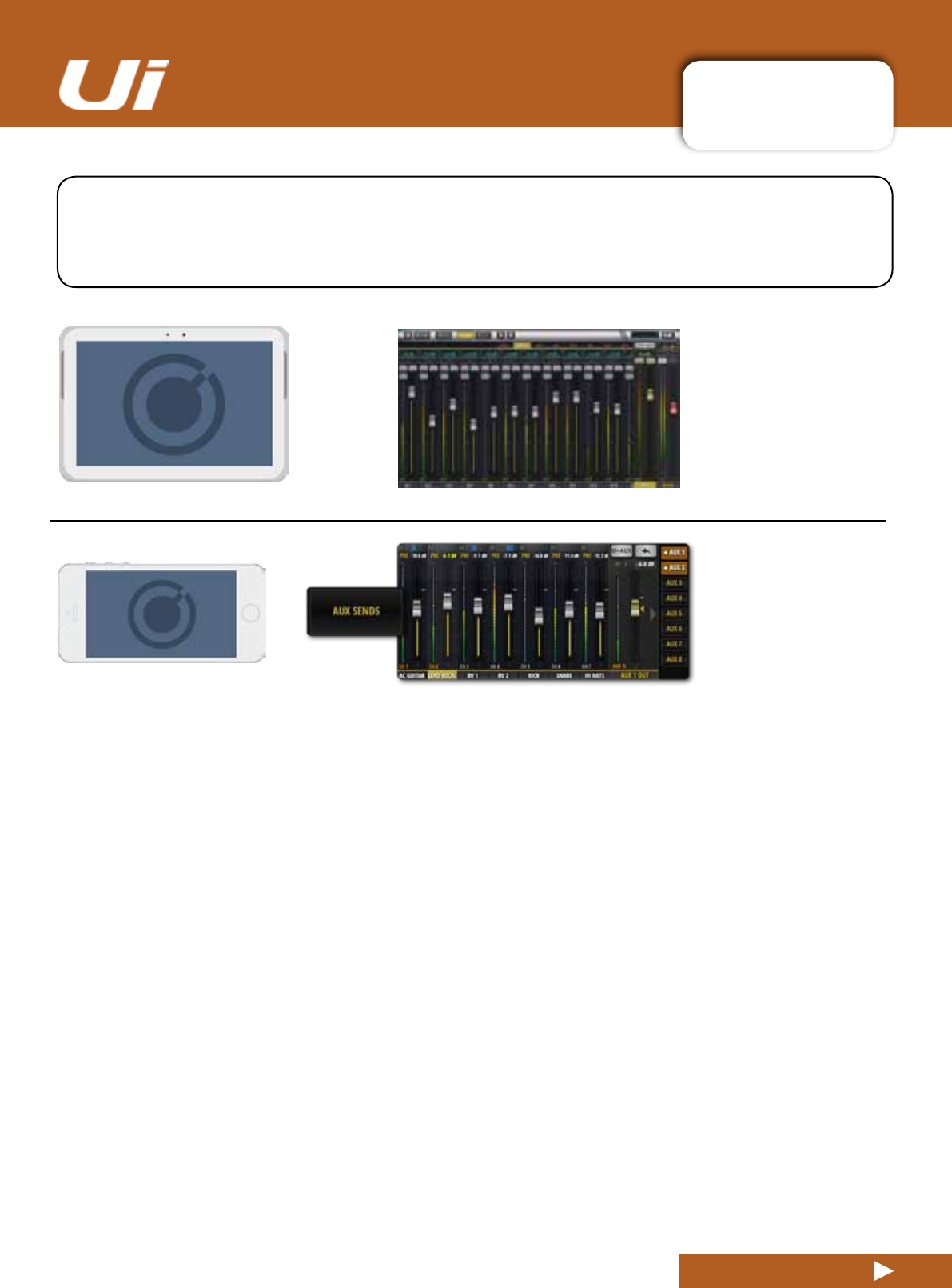
2.4: GETTING CONNECTED
GETTING STARTED > GETTING CONNECTED
2.4: GETTING CONNECTED - SOFTWARE CONTROL
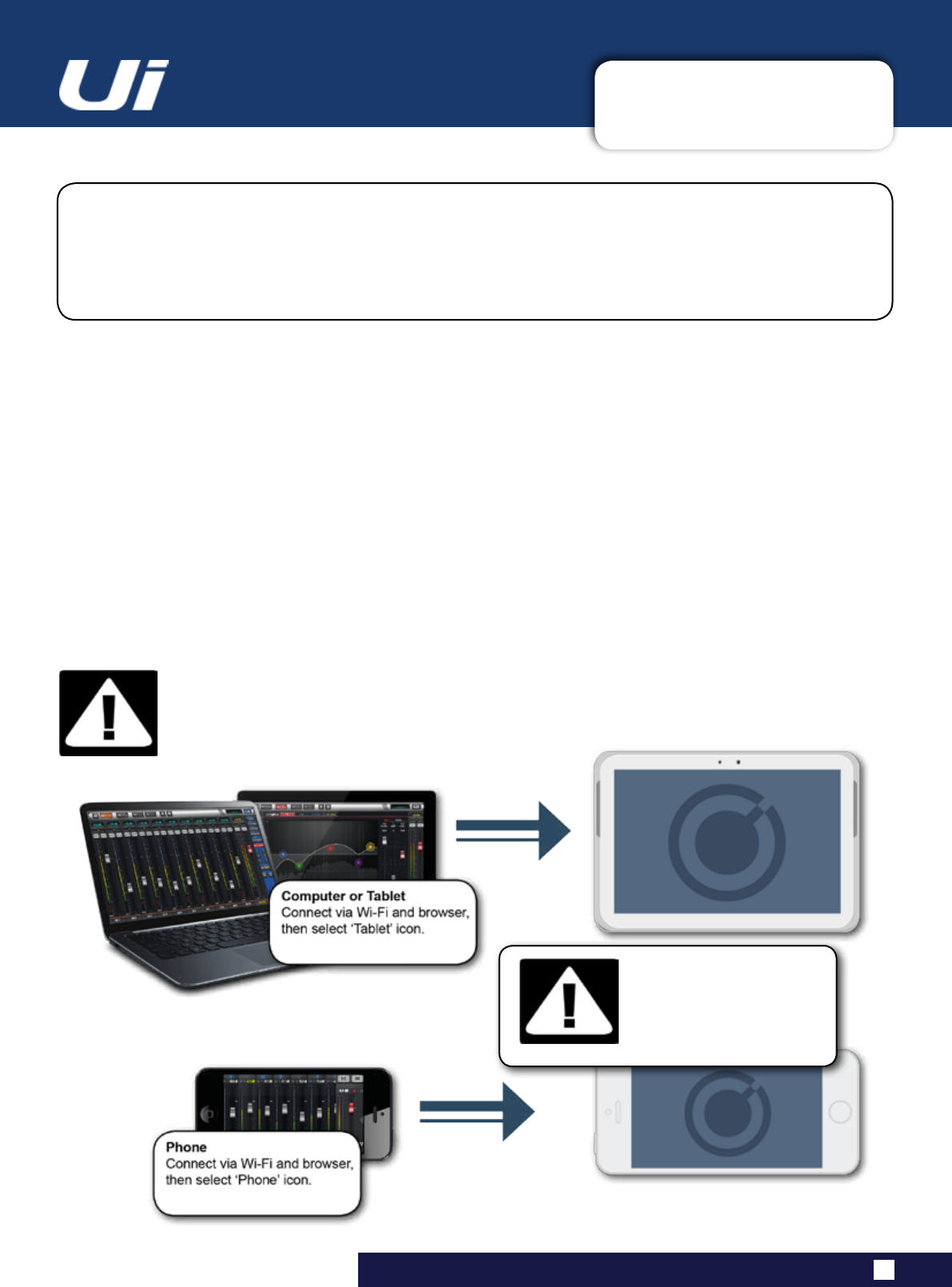
The Soundcraft Ui series uses built-in web server technology to enable computer, tablet, and
phone-basedin-browsercontrolofallfunctions-simplyconnecttotheUiWi-Fiaccesspoint(hotspot)
and browse to the appropriate URL. Alternatively, you can connect via an existing Wi-Fi network, or via
awiredLAN(LocalAreaNetwork)usingtheEthernetportonthesideoftheunit.SeeSection10.1for
detailsonnetworkconguration.
Ui24R User Manual
Connecting To Ui Hotspot with computer, tablet, or phone.
1)EnsuretheWi-Fiantennaisattachedtotheunit,connecttheexternalpowersupply,andturnonthe
powertoyourmixer.YouwillseeanLEDlightupinsidetheWi-FilogoonyourUihardware;thiswillash
until booted successfully.
2)NavigatetoWi-Fiset-uponyourdeviceandconnecttothe“SoundcraftUi24”accesspoint.Ifthisisthe
rsttimeyouhaveconnected,thedefaultpasswordwillbe‘scuiwlan’. (by default it will not have a pass-
word, please assign one that you can remember)
3)Launchyourdevice’sbrowser,andentertheURLui.io. For Android users, you must use Android brows-
er 4.4 or later, or other modern browsers like Chrome to use the Ui web app. In some cases where certain
protection software is running on a system you may need to enter the ip address 10.10.1.1
4)Youshouldseethedeviceselectionscreenshowingiconsforlargescreen(tabicon)andsmallscreen
IMPORTANT!
Thersttimeyouconnect,itisimportanttosetupanewpasswordforWi-Fiaccess.Press
theSettingsicon,thenchoosethersttab:‘NETWORK’toaccessthepasswordeld.
DEFAULT HOTSPOT
PASSWORD:
scuiwlan
Ui24R User Manual 3.0: SOFTWARE CONTROL
SOFTWARE CONTROL
3.0: SOFTWARE CONTROL
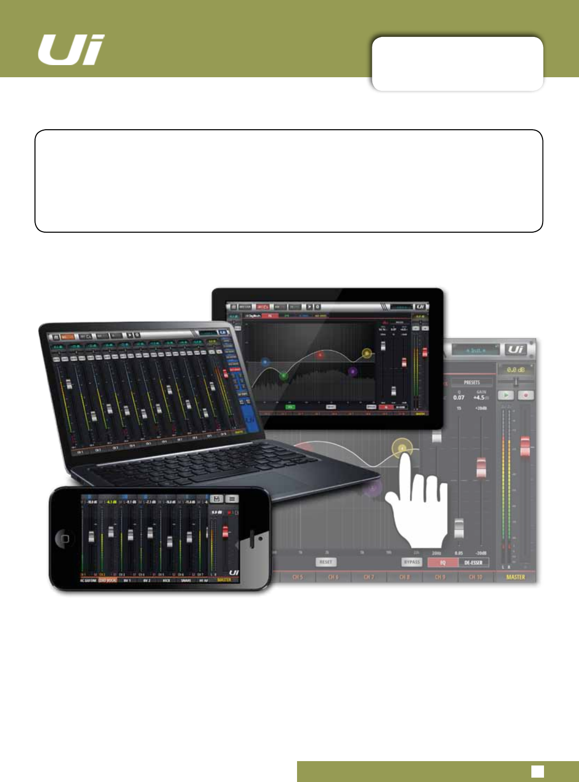
The browser-based software control for the Ui Series is available to any device in two versions.
Thesmall-screenversionisoptimisedforphone-sizeddevices;thelarge-screenversionisoptimised
for tablets and computers.
In order to make best use of your Ui mixer, please read this section of software control. There are
several navigation and menu access functions that will greatly simplify Ui control.
Ui24R User Manual 3.0.1: UPDATES & REQUIREMENTS
SOFTWARE UPDATES & REQUIREMENTS
3.0.1: SOFTWARE UPDATES & REQUIREMENTS
The browser-based software control for the Ui Series actually runs from a virtual web server in the
main Ui unit itself and is compatible with any modern browser software running on your control
device. For Android users, you must use Android browser 4.4 or later, or another modern browser like
Chrome to use the Ui web app.
Upto10controldevicescanbeusedsimultaneously.(Dependingonavailablebandwidth)
Software Updates
Regular software updates are posted on the Soundcraft website and are available from the product page.
In the Tablet software you can check your current Ui software version by navigating to the SETTINGS page
and selecting the ABOUT tab. In the Phone software you can check your current Ui software version by
navigating to the SETTINGS page and selecting the HELP tab.
To update the Ui software:
1.DownloadtheUiupdatelefromthewebsiteandleavein.zipformat.
2.Copythe.zipletoaUSBmediadevicesuitableforconnectiontoaUimixer’sUSBport.Note:Thele
can reside in any directory. Any USB port on the mixer is also acceptable.
3. Ensure your client device is connected to the Ui mixer GUI
4. Connect the USB media
5.TheGUIdisplaywilldisplaythattheUSBdevicehasbeenmounted.Afterthestickhasbeenread(may-
be10moreseconds)theupdatewillberecognised.
6. The GUI will ask if you would like to update. Choose OK.
7. The mixer will perform the update
8. The GUI will present a message stating whether the update has been successful or not.
9. You must power-cycle the unit and reconnect a client device.
10. You can browse to the about page to see the new Firmware version information.
IMPORTANT!
Notethatifyouhaveanytypeofziple(otherthantheupdatele)inanydirectoryonthe
USB key already, the software update will not work. Note Mac OS by default unzips down-
loadedleswhichwillrenderthermwareupdateincompatible.
USB AUDIO DRIVER
The Ui24R requires the use of the Soundcraft SI Impact Audio Driver for multichannel USB playback and
recording.
It can be downloaded via:
http://www.soundcraft.com/en/softwares/soundcraft-multichannel-usb-audio-driver-v3-20 or above

Ui24R User Manual 3.0.2: RESET THE MIXER
SOFTWARE > RESET THE MIXER
3.0.2: RESET THE MIXER
TherearetwolevelsofresetfortheUimixer.Therstwillresetnetworksettingsintheeventthatyou
areunabletoconnect.Thesecond(usesafullreset.txtleonaUSBmemorystickinconjunctionwith
theresetbutton.Thiswillfullyresettheunitbacktoitsfactoryrmwareanddefaultsettings.
Full Reset
This method removes all updates you may have performed on the mixer and returns the unit to its
defaultfactoryshippingrmwareandstate.Allsettings,snapshots,users,prolesandshowswillbelost.
Please ensure you have saved/backed up any shows before resetting your Ui.
1)Createatestlenamedfullreset.txt(nocontentsnecessary)andcopytoaUSBstick
2)InserttheUSBstickintooneoftheUi’sUSBports.
3)Useaslim,longobjecttoholdtheresetbuttondownforapproximately10secondswhileyoupoweron
the unit.
4)TheUiwillrecognisethefullreset.txtleontheUSBstickandperformafullfactoryreset.
5)Youmustpowercycletheunitandreconnecttheclientdevice.Poweroffforatleast10-15secondsbe-
fore powering back on.
Note: Aickofthepoweroff/onwillalmostalwaysfailtobootproperly,andcangetstuck(withcontinuous
ashingblueWi-FiLED).Makesuretopoweroff,wait10-15seconds,thenpoweron.TheblueWi-FiLED
willpulse/ashforaround10-15secondsthenremainon.
Networking Reset
Reset Networking and Admin password if you have forgotten the admin password or if you are no longer
able to connect to the Ui.
Useapaperclip(orsimilar)toholddowntherecessedresetbutton(sidepanel)downforapproximately
10secondswhileyoupowerontheunit.ThiswillinitialisetheUi’snetworkingandadminpasswordtothe
default state.
3.1: SOFTWARE NAVIGATION
SOFTWARE > SOFTWARE NAVIGATION
3.1: SOFTWARE NAVIGATION
Ui24R User Manual
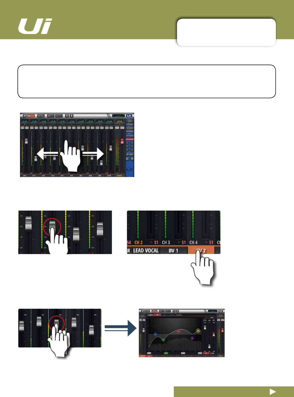
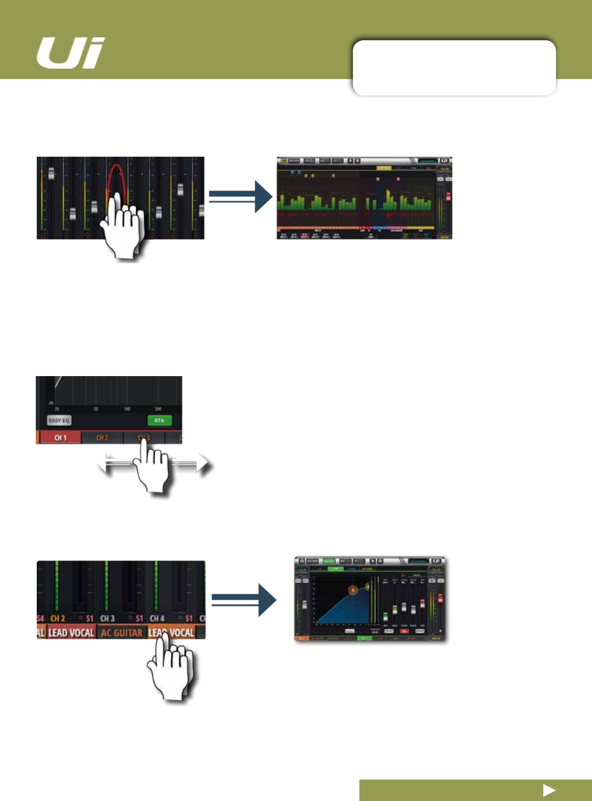
Scroll Mixer
Touch /Click and slide on the mixer screen to scroll
along to whole available mixer - including FX Send, Aux
Send and Group masters.
Fader / Channel Name
Select a channel by touching or clicking on a fader or channel name.
Theselectedchannelwillremainactive(keepfocus)regardlessof
function screen until a new channel is selected.
Double Tap Fader
Access the channel EQ from MIX Screen. Double tap or double click.
There are many navigation / gesture techniques common to both the Tablet and Phone versions of the Ui
control software. This section describes the main ones. Section 3.7 summarises all control gestures.
Please Note: The screen shots shown are from the phone version of the software, except where the two
differsignicantlyincontent.
3.1: SOFTWARE NAVIGATION
SOFTWARE > SOFTWARE NAVIGATION
3.1: SOFTWARE NAVIGATION
Ui24R User Manual
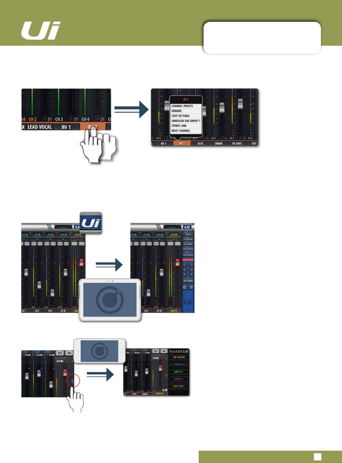
Scroll Channel Names
Touch/click-hold and slide on channel names to access channel
names across the whole mixer, including FX Sends, Aux Sends, and
Group Faders.
Double Tap Channel Name
Phone: Access the Dashboard screen for that channel - access to
EQ, dynamics, Aux and FX Sends, and more.
Tablet: Access EDIT Page > Dynamics tab.
Double Tap Channel Strip
Double tap anywhere except the fader to access the METERS screen or switch back to the MIX screen from the
GAIN screen.
3.1: SOFTWARE NAVIGATION
SOFTWARE > SOFTWARE NAVIGATION
3.1: SOFTWARE NAVIGATION
Ui24R User Manual
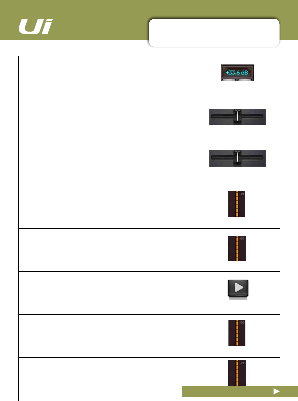
Long (held) Tap/Click
Alongtap/clickoncertaincontrolsbringsupasub-menuspecictothatcontrol.Forexample,alongholdor
click on a channel name gives access to channel presets, renaming, copy/paste settings, sub group assignment,
stereo linking, channel reset, and the ASSIGN ME function.
Slideout View
Touch the Slideout Arrow to the right of the
MIX screen to access the Slideout View
panel.
For the tablet software Slideout panel,
click/touch the Ui button in the top right
corner of the screen. The tablet Slideout
offers fast mixer navigation to common
channel groups, MUTE and VIEW group
access, the TAP TEMPO button, plus
MUTE ALL and MUTE FX functions.
On the phone software this gives fast ac-
cess to the TAP TEMPO and MUTE FX
buttons,plusJUMPTO(mixernavigation),
GROUPS(Mute&ViewGroups),and
FUNCTIONS(fastfunctionssuchas
playbackandrecord)options.
You can pin the Slideout View in place via
the SETTINGS Screen.
3.1.1: CONTROL / GESTURE SUMMARY
SOFTWARE > CONTROL SUMMARY:MIX PAGE SHORTCUTS
3.1.1: CONTROL SUMMARY
Ui24R User Manual
Double Click/Tap on
Virtual LCD Display
to return Channel Volume to 0db
Single click/tap on channel Pan or
Balance control zone
to temporarily display channel Pan
or Balance value in relative virtual
channel LCD display
Double click/tap on channel Pan
or Balance control
to centre channel Pan or Balance.
Double click/tap in INPUT channel
stripzone(excludingfadercap)
to navigate to METERS Page
Double click/tap in LINE INPUT
channelstripzone(excludingfader
cap)
to navigate to METERS Page
Double click/tap in PLAYER chan-
nelstripzone(excludingfadercap)
to navigate to PLAYER/MEDIA
Page.
Double click/tap in FX RETURN
channelstripzone(excludingfader
cap)
to navigate to FX SENDS Page
Double click/tap in SUG GROUP
channelstripzone(excludingfader
cap)
to navigate to METERS Page
3.1.1: CONTROL / GESTURE SUMMARY
SOFTWARE > CONTROL SUMMARY:MIX PAGE SHORTCUTS
3.1.1: CONTROL SUMMARY
Ui24R User Manual
Double click/tap in AUX MASTER
channelstripzone(excludingfader
cap)
to navigate to AUX SENDS Page
Double click/tap on channel fader
cap to navigate
to channel EDIT mode EQ tab
Double click/tap on channel label
(channeltypes:INPUT,LINEIN,
PLAYER,SUBGROUP,AUX)
to navigate to selected channel
EDIT page DYN tab.
Double click/tap on channel label
(channeltype:FXRETURN)
to navigate o selected channel
EDITpageFXtab(GlobalFXpa-
rameters)
Long click/press and hold on
channel label
to engage channel pop-up menu.
Single click/tap on top level navi-
gation panel virtual LCD display.
to engage shows/snapshot pop-up
list short-cut activator
Long click/press-and-hold on top
level navigation panel virtual LCD
display
to navigate to SETTINGS page
SHOWS tab
Single click/tap on MASTER
channel virtual LCD display
to navigate to METERS Page
3.1.1: CONTROL / GESTURE SUMMARY
SOFTWARE > CONTROL SUMMARY:CHANNEL EDIT PAGE PARAMETRIC EQ
3.1.1: CONTROL SUMMARY
Ui24R User Manual
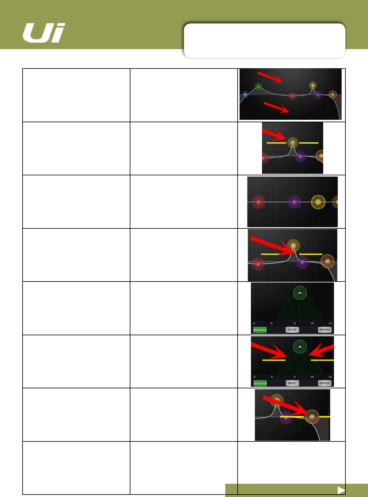
Double click/tap in vacant space to navigate to MIX page.
Drag PEQ frequency balls toadjustdBgain(upanddown)
andfrequencyvalues(leftand
right)
Double click/tap frequency balls to reset selected frequency band to
0dB and default frequency.
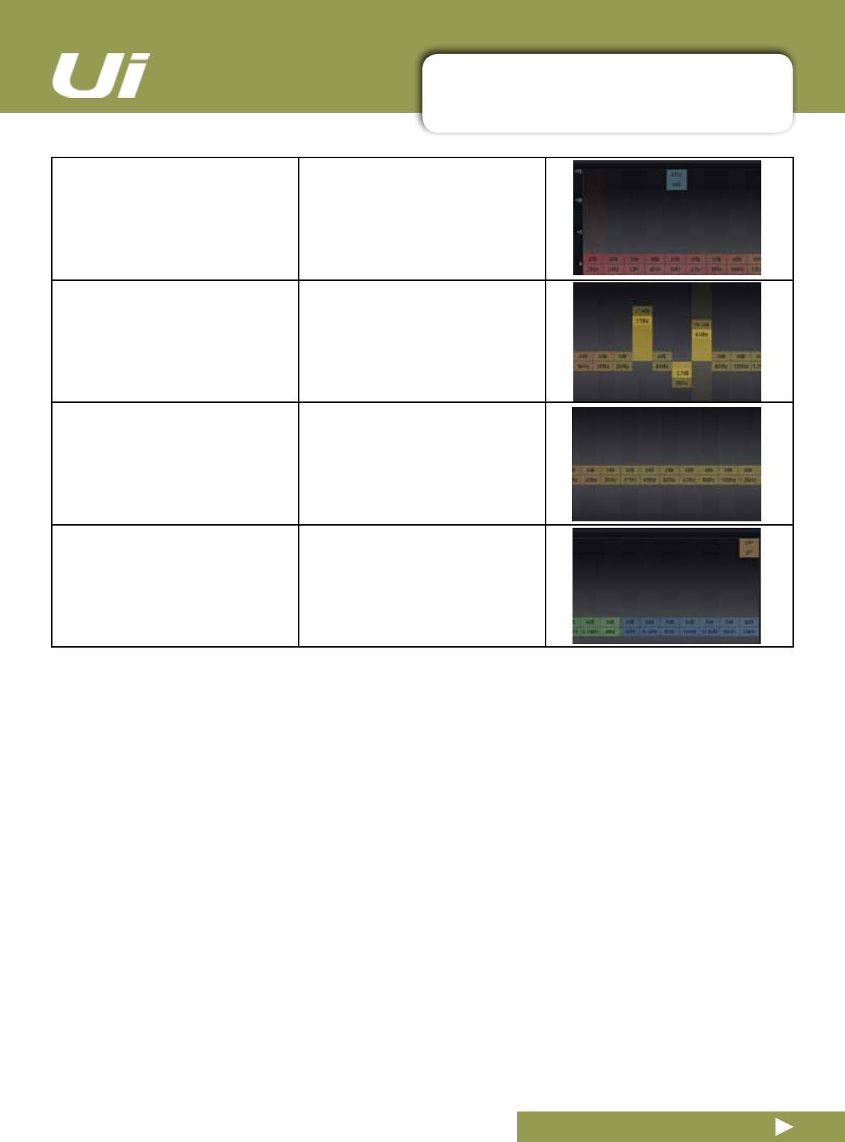
Pinch-gesture or mousewheel/
trackpad scroll on selected fre-
quency ball
to adjust Q value
Drag DE-ESSER frequency ball to adjust frequency and dB thresh-
old values.
Pinch-gesture or mousewheel/
trackpad scroll on DE-ESSER
frequency ball
to adjust ratio value.
Drag LPF/HPF frequency ball to adjust LC/HPF frequency value.
Note: The slope of the curve can
also be adjusted by selecting the
desired curve from the right panel
menu.
3.1.1: CONTROL / GESTURE SUMMARY
SOFTWARE > CONTROL SUMMARY:CHANNEL EDIT PAGE GRAPHIC EQ
3.1.1: CONTROL SUMMARY
Ui24R User Manual
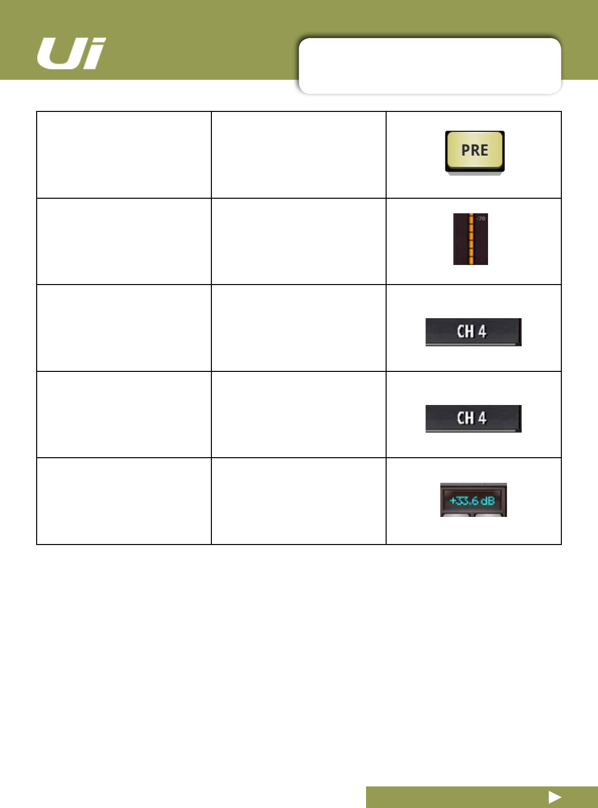
On Master EQ and AUX1-2 you
may also DRAG HPF and LPF
EQ’s to select the desired fre-
quency.
Note, only available on MASTER
Left/Right and AUX/MATRIX 1 and
2.
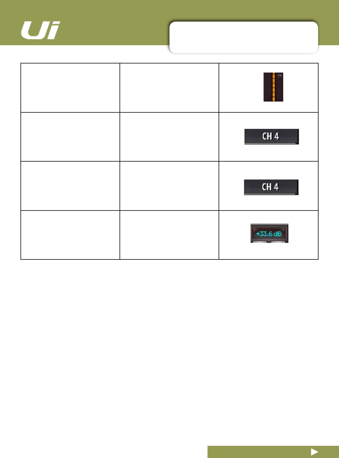
GEQ frequency to adjust dB gain of selected fre-
quency.
Double click/tap GEQ frequency to reset selected frequency to 0dB.
Drag GEQ to see the rest of the
frequencies (size depends on
screen size being used)
Top Left hand corner you will see a
representation of all 31 bands
3.1.1: CONTROL / GESTURE SUMMARY
SOFTWARE > CONTROL SUMMARY:CHANNEL EDIT:AUX SENDS
3.1.1: CONTROL SUMMARY
Ui24R User Manual
Long click/press-and-hold chan-
nel strip PRE/POST button
for‘setallPreorPost’option.
Double click/tap in channel send
stripzone(excludingfadercap)
to navigate to MIX Page.
Double click/tap on channel label to navigate to selected channel
EDIT page DYN tab.
Long click/press-and-hold on
channel label
to engage channel pop-up menu
Double click/tap in channel LCD to‘ReturnToZeroLevel’
3.1.1: CONTROL / GESTURE SUMMARY
SOFTWARE > CONTROL SUMMARY:CHANNEL EDIT:FX SENDS
3.1.1: CONTROL SUMMARY
Ui24R User Manual
Double click/tap in channel send
stripzone(excludingfadercap)
to navigate to MIX Page.
Double click/tap on channel label. to navigate to selected channel
EDIT page DYN tab
Long click/press-and-hold on
channel label
to engage channel pop-up menu.
Double click/tap in channel LCD to‘ReturnToZeroLevel’
3.1.1: CONTROL / GESTURE SUMMARY
SOFTWARE > CONTROL SUMMARY:CHANNEL EDIT:FX SENDS
3.1.1: CONTROL SUMMARY
Ui24R User Manual
Double click/tap in channel strip
zone(excludingfadercap)
to navigate to MIX Page.
Double click/tap on channel fader
cap
to navigate to channel EDIT mode
EQ tab.
Double click/tap on channel label to navigate to selected channel
EDIT page DYN tab
Long click/press-and-hold on
channel label
to engage channel pop-up menu.
3.1.1: CONTROL / GESTURE SUMMARY
SOFTWARE > CONTROL SUMMARY:SLIDEOUT PANEL SHORTCUTS
3.1.1: CONTROL SUMMARY
Ui24R User Manual
List selectors
Item selections available in list
boxes can be made by double
clicking/tapping on a selection
inadditiontousinga‘load’button
trigger.
Long click/press-and-hold on
SUB GROUPS
tonavigatetoSubGroupcongu-
ration(METERSpage,SUBStab.)
Long click/press-and-hold on
VIEW GROUPS
tonavigatetoViewsconguration
(METERSpage,VIEWStab)
Long click/press-and-hold on
MUTE GROUPS
to navigate to Mute Groups con-
guration(METERSpage,MUTES
tab).
Long click/press-and-hold on
TAP TEMPO
for numeric tempo entry.
At anytime you may click on the HOME button to get back to the main mixer. It is recommeded for
easy use to select the BIGGER SLIDOUT panel from the settings menu and PIN it to the mixer so
it is available at any time.
3.1.1: CONTROL / GESTURE SUMMARY
SOFTWARE > CONTROL SUMMARY:CHANNEL EDIT PAGE
3.1.1: CONTROL SUMMARY
Ui24R User Manual
Digitech Tab:
Single click/tap on amp head
to bring up amp list selector
Digitech Tab:
Single click/tap on cabinet
to bring up cab list selector
DYN Tab:
Double click/tap in vacant space
to navigate to MIX page.
DYN Tab:
Drag threshold ball.
to adjust dynamics threshold value
DYN Tab:
Drag ratio ball
to adjust dynamics ratio value
FX Tab:
Double click/tap in vacant space.
to navigate to MIX page
FX Tab:
Single click/tap in virtual FX rack
for Preset Manager
AUX Tab:
Double click/tap in vacant space
to navigate to MIX page.
3.1.1: CONTROL / GESTURE SUMMARY
SOFTWARE > CONTROL SUMMARY:METERS PAGE
3.1.1: CONTROL SUMMARY
Ui24R User Manual
Single click/tap on any channel
meter VU zone
to navigate to relevant channel on
MIX page.
Long click/press-and-hold on
TAP button
for numeric tempo entry.
3.1.1: CONTROL / GESTURE SUMMARY
SOFTWARE > CONTROL SUMMARY/SHORTCUTS
3.1.1: CONTROL SUMMARY
Ui24R User Manual
SLO-MO FINE ADJUSTMENT
Hold on fader
Allowsuneadjustmentofparam-
eters for greater accuracy.
SET TO ZERO
Double Click
Double click on any parameter will
reset back to zero
JUMP TO METERS/AUX
Double Click
Double click on any channel will
open up same channel in Meters/
Aux pages
JUMP TO EQ/DYN
Double Click
Double Click etc.
CHANGE FX
Press and Hold
Will bring up pop menu for quick
change of effects
DOTTED TABS
Press and Hold
Any tab with dot in right corner will-
have a shortcut function that can be
activated via pressing and holding.
3.2: TABLET NAVIGATION
SOFTWARE > TABLET / LARGE SCREEN NAVIGATION
3.2: TABLET NAVIGATION
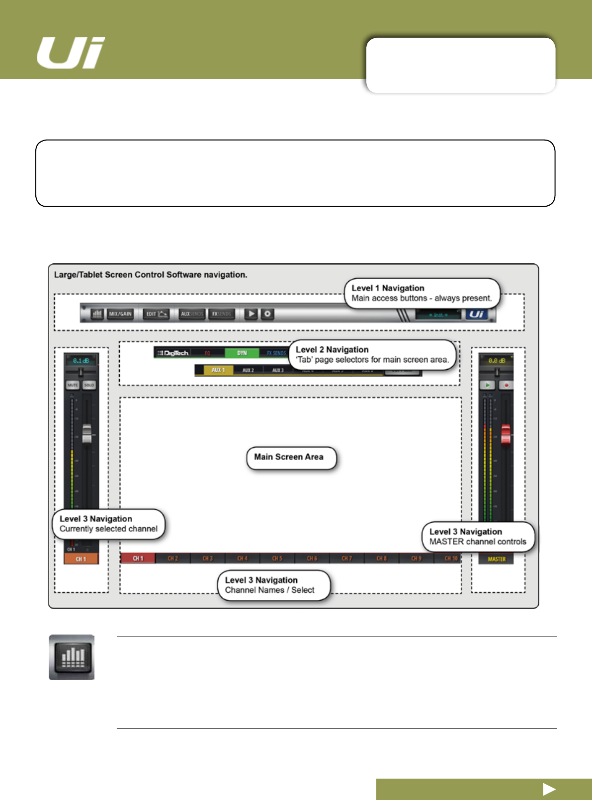
The MIX Screen is the default for the Ui tablet / large screen software - You can navigate from there to
other screens and functions in a variety of ways. The Level 1 Navigation controls take you directly to
variousprimaryscreens,Level2navigation(pagetabs)switcheslayerswithintheselectedscreen,and
Level 3 navigation controls select individual channels.
Ui24R User Manual
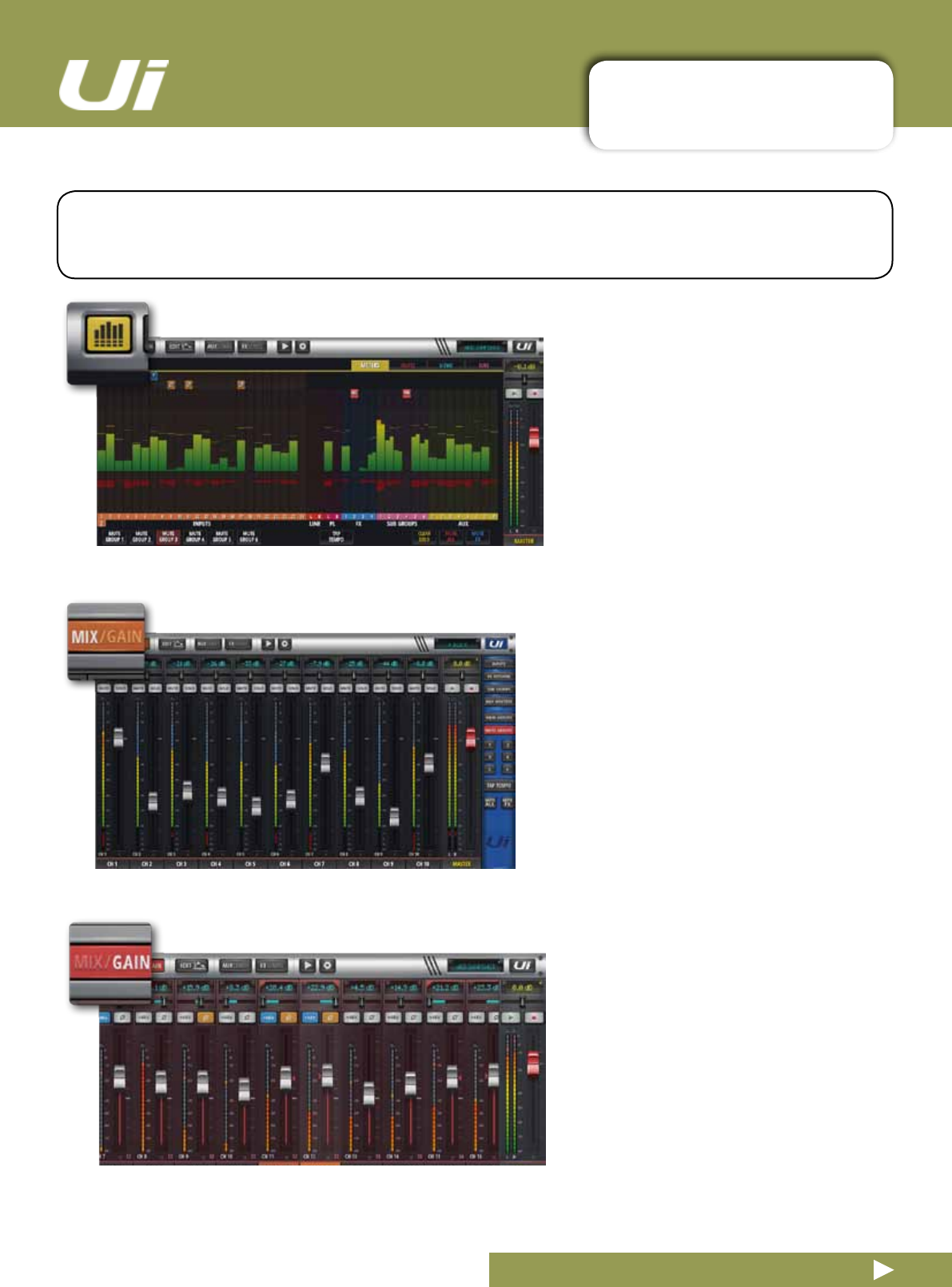
METERS
Access the METERS page
TabsonthispageareMETERS,(meters&status),MUTES,VIEWS,,VCA’sandSUBS(SubGroups).The
default meters page shows status for phantom power, phase, mute, and solo, plus bargraph metering for
level,gainreduction(dynamics).Youcanactivatemutegroups,useTapTempo,andCLEARSOLO,MUTE
ALL, AND MUTE FX directly from this page.
3.2: TABLET NAVIGATION
SOFTWARE > TABLET / LARGE SCREEN NAVIGATION
3.2: TABLET NAVIGATION
Ui24R User Manual
EDIT
Access the EDIT page for the selected channel
Resultingpagecongurationdependsonselectedchannel.Forexample,theEDITpageforaninputchan-
nel will have EQ, Dynamics, Aux Sends, and FX Send tabs. Certain Tabs will be preselected if you navigate
from certain views. For example, selecting EDIT from the FX Sends main page will preselect the FX Sends
tab in for the
highlighted channel.
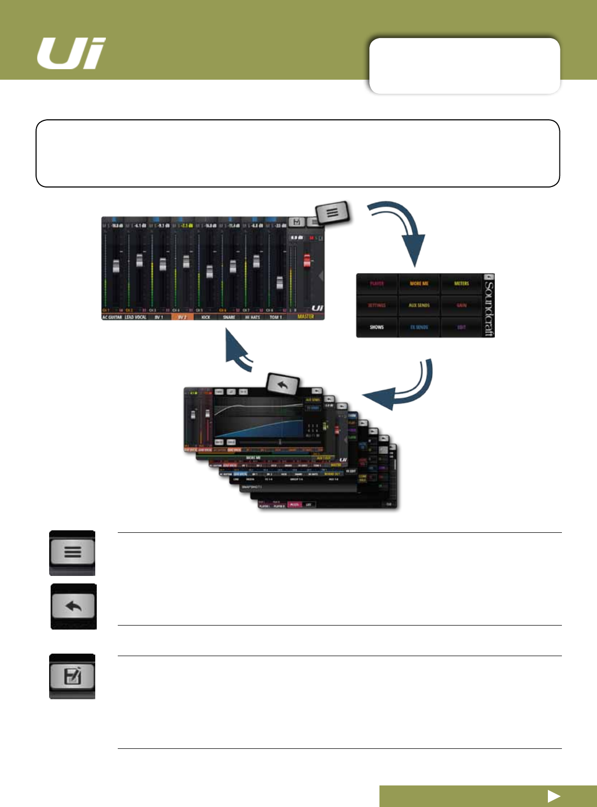
FX SENDS
Access the FX SENDS page
Shows a fader based view of all FX send levels for the selected FX Send Bus. Also shows FX Return
channel on right hand side. Selecting EDIT from the FX SENDS page will preselect the FX Send tab for the
selected input channel.
SETTINGS
Access the SETTING page
Systemandmixersettingsandcongurations.
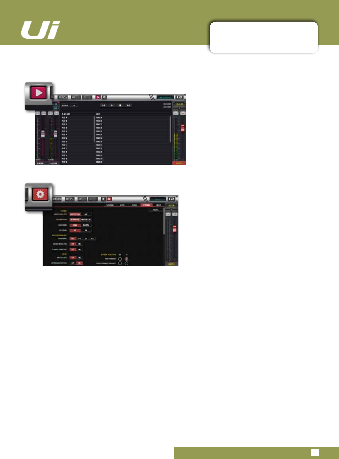
AUX SENDS
Access the AUX SENDS page
Shows a fader based view of all aux send levels for the selected aux bus. Also shows the Aux Master chan-
nel on right hand side. Selecting EDIT from the AUX SENDS page will preselect the AUX SENDS tab for the
selected input channel.
MEDIA
Access the MEDIA page
Playback and record controls, plus playlist and track selections. Also shows Playback L and Playback R
channels on left hand side.
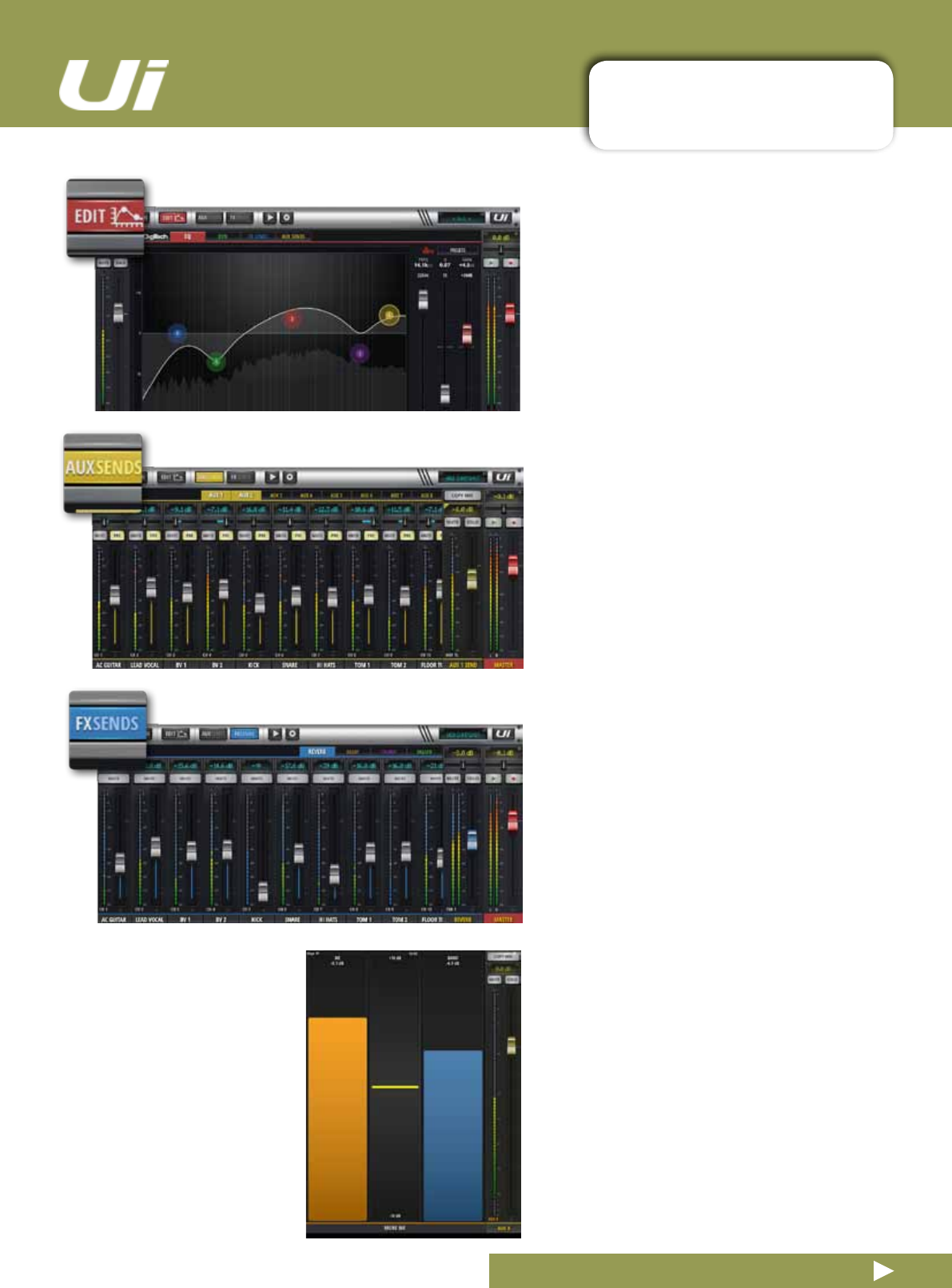
MIX / GAIN
Access the MIX and GAIN pages
Whenthebuttonisorange,theMIXpageisshown(channelfaders)andwhenthebuttonisRed,theGAIN
pageisshown(remotegainfadersandinputstagecontrols).
3.2: TABLET NAVIGATION
SOFTWARE > TABLET / LARGE SCREEN NAVIGATION
3.2: TABLET NAVIGATION
Ui24R User Manual
SNAPSHOT
Access the Show and Snapshots pop-up selector
Load shows and snapshots directly from this pop-up.
SLIDEOUT
Access the SLIDEOUT view on the right hand side of the screen
Offersfastviewandstatusswitchingfunctionality.TheSlideoutviewcanbeconguredas‘pinned’
(permanent)intheSETTINGSpageforMixandAux/FXSendspagesindependently.

3.2.1: KEYBOARD CONTROL
SOFTWARE > KEYBOARD CONTROL and shortcuts
3.2.1: KEYBOARD CONTROL
For users mixing with a device that has a keyboard, please see below a set of easily accessible key com-
mands,makingitquickandefcienttoaccessthemostusedfeaturesonthemixer.
Ui24R User Manual
Keys
1 = Meters
2 = Toggle Mix/Gain
3 = Edit
4 = Aux Sends
5 = FX Sends
6 = Player
7 = Settings
8 = Slide Out
9 = Meters
q = Toggle Inputs
w = Toggle FX Masters
e = Toggle Sub Group Masters
r = Toggle Aux Masters
t = Toggle VCA Masters
p=channelpresets(forchannelsthathavechannelpresets)
a = Mute All
s = solo currently selected hannel
f = Mute FX
x = 2-track record
c = Currently selected channel pop menu
m = Mute currently selected channel
Space bar = Slide Out
tab = toggle through L2 tabs
Back space = last page
Right Arrow = Select next channel
Left Arrow = Select previous channel
Up Arrow = Bank jump forward to next visible channel
Down Arrow = Bank jump backwards to next visible channel
ESC key = Take me home

3.2.1: KEYBOARD CONTROL
SOFTWARE > GUI shortcuts
3.2.1: KEYBOARD CONTROL
Ui24R User Manual
Nav bar LCD - long click to jump to SETTINGS->SHOWS
Master channel strip LCD - click to toggle view between MIX and METERS page
Pan slider - single click to show value in LCD
Pan slider - Double click to reset to CENTER
Fader cap - Double click fader cap to jumpt to EDIT->GEQ
Fader cap if MASTER LOCK ENABLED and HOLD FADER FOR FINE TUNING ON in Settings:
- Long click 2 sec to temporarily unlock and adjust fader value
-Longclick4sectoHOLDFADERFORFINETUNING(ifmasterlockinnotON,HOLDFADERFOR
FINETUNINGissetto2seconds)
Channel label - long click to enable channel pop menu
Meters page
Channel meters - click to select channel and jump to MIX page
Free space in METERS->MUTES/VIEWS/SUBS/VCA - Double click in free speace to return to MIX page
MIX page
Channel Strip
Channel LCD - Double click to reset to 0dB
Channel LCD - Long click to manually enter value
Pan slider - single click to show value in LCD
Pan slider - Double click to reset to CENTER
Channel strip Inputs/LINE/SUB GROUPS - Double click strip/VU zone to go to Meters
Channel strip PLAYER - Double click to go to Player page
Channel strip FX Master strip zone - Double click to go to FX Sends
Channel strip AUX Masters - Double click to go to AUX Sends
Fadercaps-DoubleclickfadercapstojumpttoEDIT->EQ(exceptVCA)
Channel labels - long click to enable channel pop menu
Channellabels-doubleclicktojumptoEDIT->COMP(excludesFXMasters)
Channel labels FX Masters - double click to jump to EDIT->FX SENDS
EDIT PAGE
Generally double clicking in free space will return the user to the MIX page
AUX Sends
Tab key to toggle through AUX Master channels
Channel strip zones - Double click to go to Mix page
FX Sends
Tab key to toggle through FX Master channels
Channel strip zones - Double click to go to Mix page
Small Slide Out
Sub group button - Long click to jumpt to METERS->SUBS
View group button - Long click to jump to METERS->VIEWS
Mute group button - Long click to jump to METERS->MUTES
Tap Tempo button - Long click to manuall enter Tempo
Big Slide Out
Mute group buttons - Long click to jump to METERS->MUTES of the currently selected group
View Group buttons - Long click to jump to METERS->VIEWS of the currently selected group
Tap Tempo button - Long click to manuall enter Tempo value
Generally double clicking in free space will return the user to the MIX page
Tap tempo button - long click to enter manual value
3.3: TABLET SCREENS
SOFTWARE > TABLET SOFTWARE SCREENS
3.3: TABLET SOFTWARE SCREENS
The main tablet software screens are accessed from the level 1 Navigation Buttons along the top of the
screenarea,orviafast-accessroutes,suchasdouble-tappingonafadertoaccesstheEQscreen(see
section3.1).
Ui24R User Manual
MIX
MIX is the most used screen and includes
a scrollable display of every channel
fader. The channel order from left to right
is: input channel faders, line in faders,
media player faders, FX return faders,
Sub Group faders, and AUX Master
faders. The Ui hardware you own will
determine how many channels you see in
the control software.
METERS
TheTabsareMETERS(forallchannels),
MUTES(MutegroupAssignment),VIEWS
(ViewGroupassignment),andSUBS
(sub-groupassignment).
The Meters page features VU meters
and gain reduction meters for all chan-
nels, and also provides fast access to the
CLEAR SOLOS, MUTE FX, and MUTE
ALL buttons, plus all Mute Groups.
GAIN
All Ui mixer models include remote gain
control and remote phantom power.
TheGAINscreen-easilyidentiedbyits
red fader level lines - features Gain
Faders, and the phantom power and
phase invert buttons. Note: When select-
ing DAW or USB A playback these will
br disabled and another set available for
recordingaftertherst20micinputchan-
nels.
3.3: TABLET SCREENS
SOFTWARE > TABLET SOFTWARE SCREENS
3.3: TABLET SOFTWARE SCREENS
Ui24R User Manual
AUX SENDS
AUX SENDS is where the aux mixes are
created. The faders determine the level of
signal sent to the selected aux bus. Select
an aux mix from those available at the
top of the view to adjust that mix. The Aux
Master will be available on the right hand
end of the screen, next to the Master
Channel.
EDIT
The EDIT page provides access to audio
processing such as EQ, DYNAMICS, and
FX.Thespecicaudioprocessingtabs
available depend on the selected channel
type. For example, the aux outputs and
Master Channel include Graphic EQ.
FX SENDS
FX Send faders determine the mix that is
sent to the selected FX processor. First,
select which effect you wish to adjust
using the tabs, then adjust the faders
to increase or decrease the amount of
reverb you would like added to each input
channel.
Select EDIT to edit the selected FX
algorithm.
MOREME
MOREME allows users to assign their
own personal channel, and create a
personal monitoring mix with a single
large fader. MOREME channel names are
highlighted in orange. To assign an input
channel to the MOREME fader,
long-press a channel name and select the
ASSIGN ME function. Use the same
process to assign an Aux bus as ‘ME
OUT’.InTabletsoftware,selectMOREME
in the Slideout panel, or turn the ipad to
a portrait view to access the MOREME
screen.
3.3: TABLET SCREENS
SOFTWARE > TABLET SOFTWARE SCREENS
3.3: TABLET SOFTWARE SCREENS
Ui24R User Manual
MEDIA
The Ui mixer has a built in media player.
This can be used for backing tracks or for
background music in between sets. The
leplaybackisstreameddirectlyfroma
USB stick. Press the MEDIA icon to enter
the player page. Files can be played from
aplaylistordirectlyfromthelelist.Press
and hold the PLAYER channel name to
bring up the channel menu.
SETTINGS
System, network, and security settings,
as well as Shows and Snapshots
management. See section 10 for more
details.
3.4: PHONE NAVIGATION
SOFTWARE > PHONE NAVIGATION
3.4: PHONE NAVIGATION
The MIX screen is the default for the Ui software - You can navigate from there to other screens and
functions in a variety of ways. To access the Menu screen, press the NAV icon in the top right corner of the
screen. Press it again to return to the MIX screen.
Ui24R User Manual
NAV
Access the main menu screen
Wheninuse,theNAVbuttonchangestothe‘Return’icon.UsethistoreturntotheMIXscreen.
SHOWS / SNAPSHOTS
Access the Show and Snapshots load/save page.
3.4: PHONE SCREENS
SOFTWARE > PHONE SOFTWARE SCREENS
3.4: PHONE SOFTWARE SCREENS
FromtheMENUscreenyoucanaccesstheMIXscreen(Returnbutton,toprightcorner)andnineother
primary screens via the large colour-coded buttons.
Ui24R User Manual
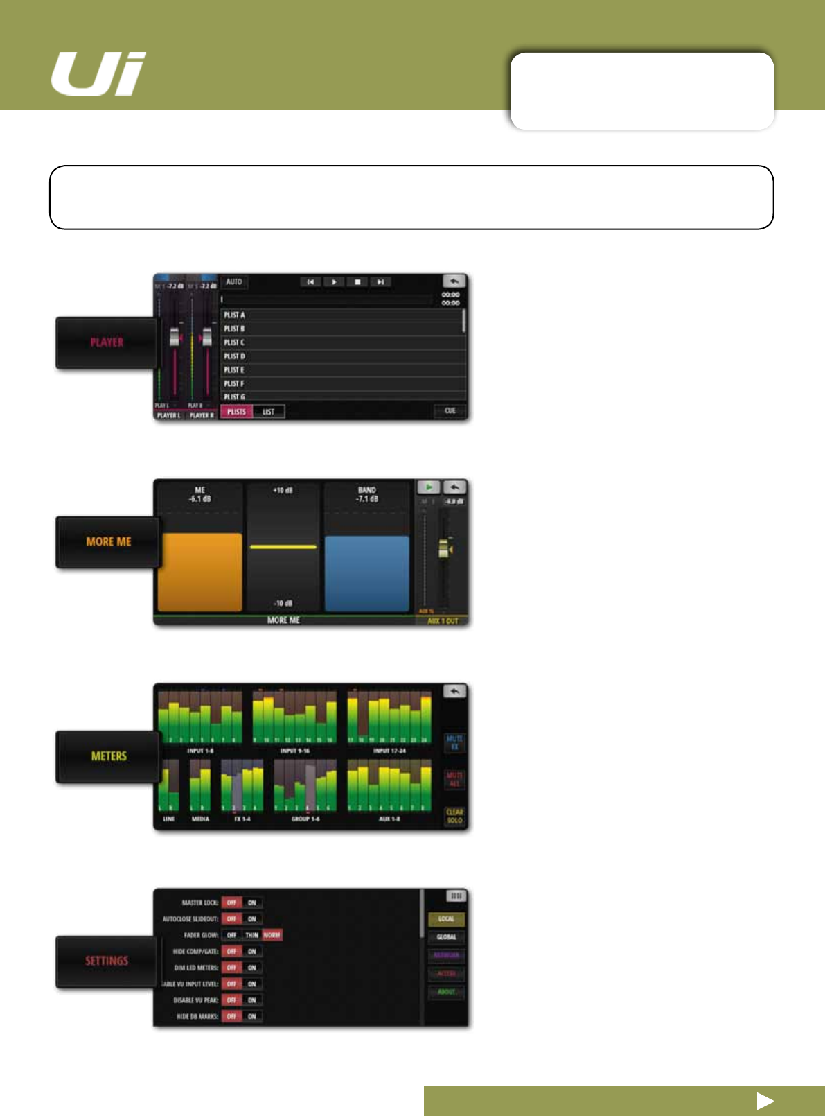
PLAYER
The Ui mixer has a built in media player.
This can be used for backing tracks or for
background music in between sets. The
leplaybackisstreameddirectlyfrom
a USB stick. Files can be played from a
playlistordirectlyfromthelelist.Press
and hold the PLAYER channel name to
bring up the channel menu.
MOREME
MOREME allows users to assign their
own personal channel, and create a per-
sonal monitoring mix with a single large
fader. MOREME channel names are
highlighted in orange. To assign an input
channel to the MOREME fader, long-
press a channel name and select the AS-
SIGN ME function. Use the same process
toassignanAuxbusas‘MEOUT’.
METERS
VU Meters for all Mixer channels, plus
status LEDs for Phantom power, Phase,
Clip, Mute, and Solo. If you press on any
meter bank, it will take you to the faders
of those channels on the MIX page. This
page also provides fast access to the
CLEAR SOLOS, MUTE FX, and MUTE
ALL buttons.
SETTINGS
A range of system settings and
congurationoptionsundertheheadings
SETUP(mixpreferences),GUI(inter-
face),NETWORK(Wi-Fihotspotand
passwordsettings),ACCESS(multi-user
security),andHELP.
3.5: PHONE SCREENS
SOFTWARE > PHONE SOFTWARE SCREENS
3.5: PHONE SOFTWARE SCREENS
Ui24R User Manual
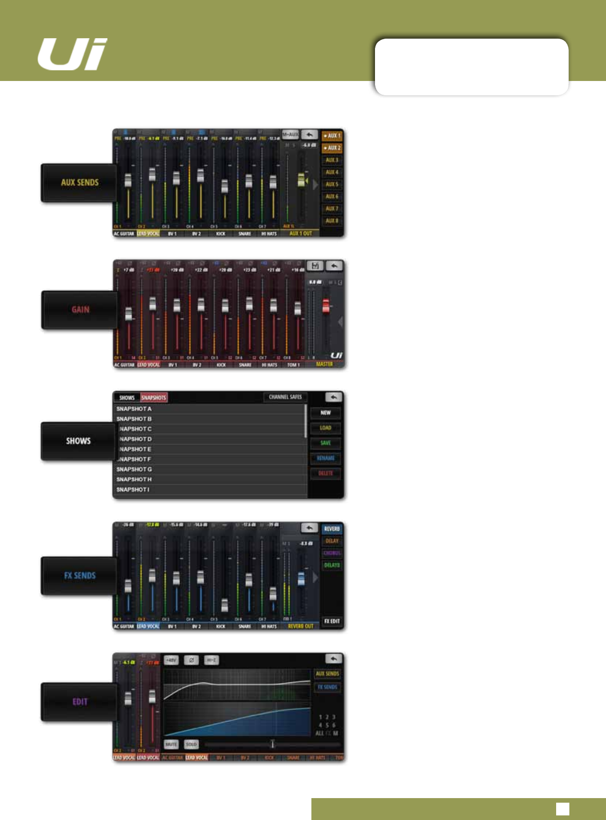
AUX SENDS
AUX SENDS is where the AUX mix is
created. The AUX input channel faders
determine the signal level sent to that
aux bus. Select an aux mix on the right to
adjust the mix from all channels.
GAIN
All Ui mixer models include remote gain
control and remote phantom power.
TheGAINscreen-easilyidentiedbyits
red fader level lines - features Gain
Faders, and the 48V phantom power and
PHASE buttons.
SHOWS
Shows and Snapshots management,
saving, and recall etc. A Show is a
collection of Snapshots. A Snapshot is a
stored set of full mixer settings.
FX SENDS
FX Send faders determine the mix that is
sent to the selected FX processor.
First, select which effect you wish to
adjust using the tabs, then adjust the
faders to increase or decrease the
amount of reverb you would like added
to each input channel. Select FX EDIT to
edit the selected FX algorithm.
EDIT
Double-Tap a channel name or select
EDIT screen to open the channel
Dashboard. This screen allows editing of
EQ, dynamics, FX and aux sends. Simply
click on the display you want and it will
open that feature in full screen.
Double-Tap the Master Channel name for
the Master EDIT page.
Ui24R User Manual 4.0: MIXER CHANNELS
MIXER CHANNELS
4.0: MIXER CHANNELS
The Ui mixers has a variety of input and output channel types. You can view all channels in the main
MIX screen and drag-scrolling along the virtual console. You can also use the MIX page Slideout
panelstoselectspecicchanneltypesandpresetviews.
INPUT CHANNEL - sections 4.1 and 4.2
AUiInputchannelconsistsofaGAINsection(physicalinput,pre-amp,phase,phantompoweretc)andthe
MIXsection.Inputchannelsfeedthemainstereobus(totheMasterChannel),theauxsendbusses(totheAux
Masterchannels),andtheFXsendbusses(andontotheFXReturns).Aninputchannel’scontributiontothese
bussesiscontrolledontherelevantsoftwarepage,orinthechannel’sEDITscreen.
AUX SENDS / AUX MASTER CHANNEL - section 4.3
AuxOutputs(shortforAuxiliary)aretheoutputsonthetoprightoftheUihardware.Theseoutputseachhave
their own mix of input sources, separate from the master mix. Generally, aux outputs are used for musicians to
heartheirownmixonstageviaastagemonitorspeakerortoheadphoneampliersforin-earmonitoring.
Alternatively, the aux outputs can be sent to external hardware FX units.
SUB GROUP MASTER CHANNEL - section 4.5
If you want to have individual control over the drum kit mix components, for example, but also want single fader
controloverthewholekit’scontributiontothemix,youwoulduseaSubGroup.
FX SENDS / FX RETURN CHANNEL - section 4.4
FX SENDS faders effectively determine the amount of effect on each input channel. They work much like aux
sends in that a mix of input channel contributions is created on the FX SENDS page - one for each FX
processor.
MASTER CHANNEL - section 4.6
TheMasterStereoChannelistheoutputchannelforthemainstereo(left&right)mix-determinedbytheinput
channel and FX Return channel faders and pan/balance controls.
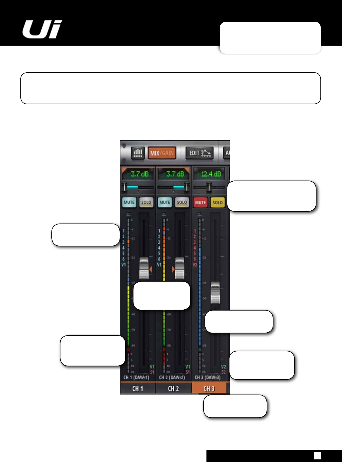
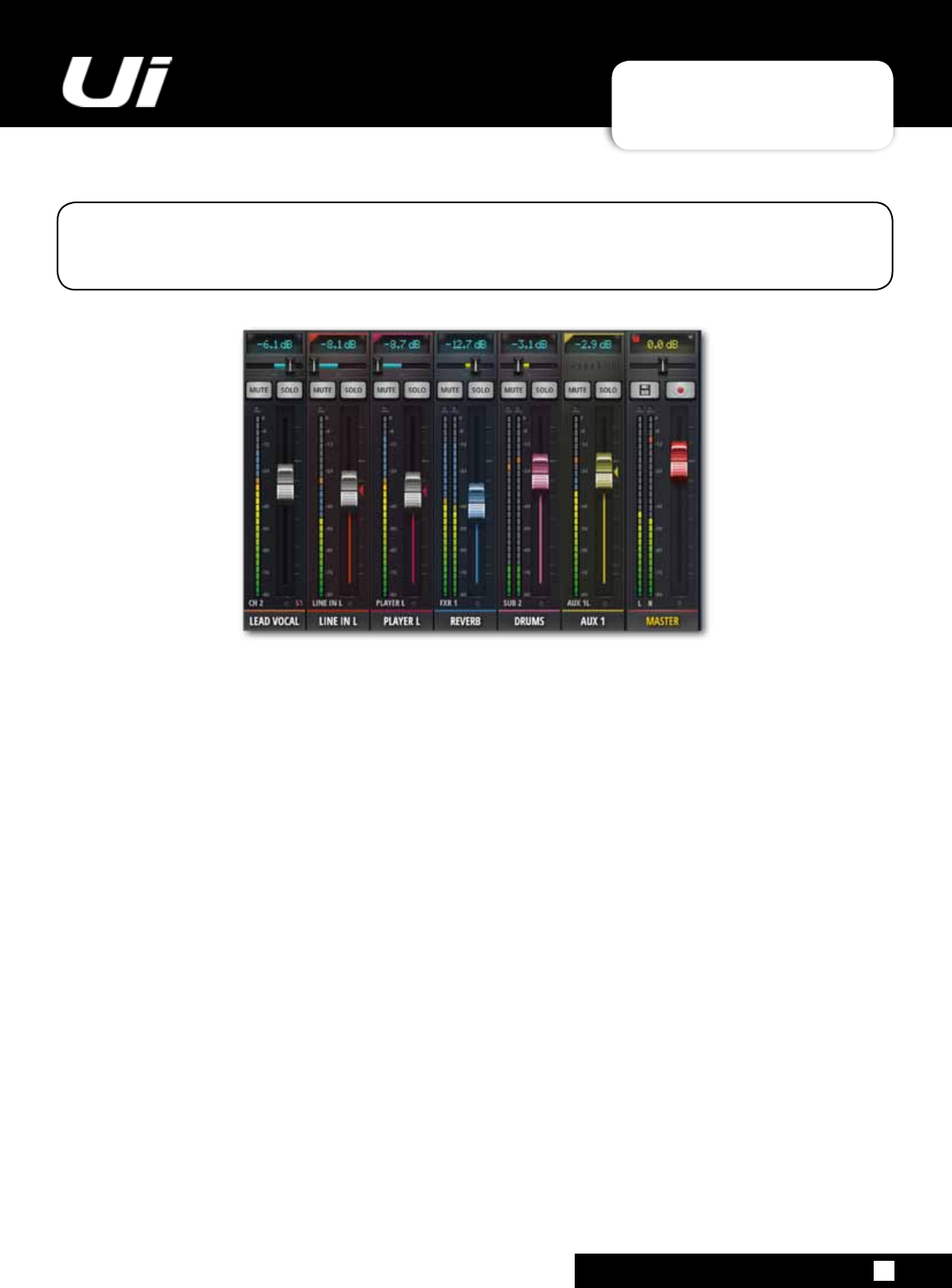
Ui24R User Manual 4.0:1 CHANNEL STRIP
CHANNEL STRIP
4.0:1 CHANNEL STRIP
TheChannelStriphasahostofinformationrightatyourngertips.Thefollowingisabreakdownof
whatausercanexpecttond.
VCA and Subgroup
indicators are displayed in
bottom RH corner when
activated.
When channel mute is
activated the gain meter is
displayed in blue.
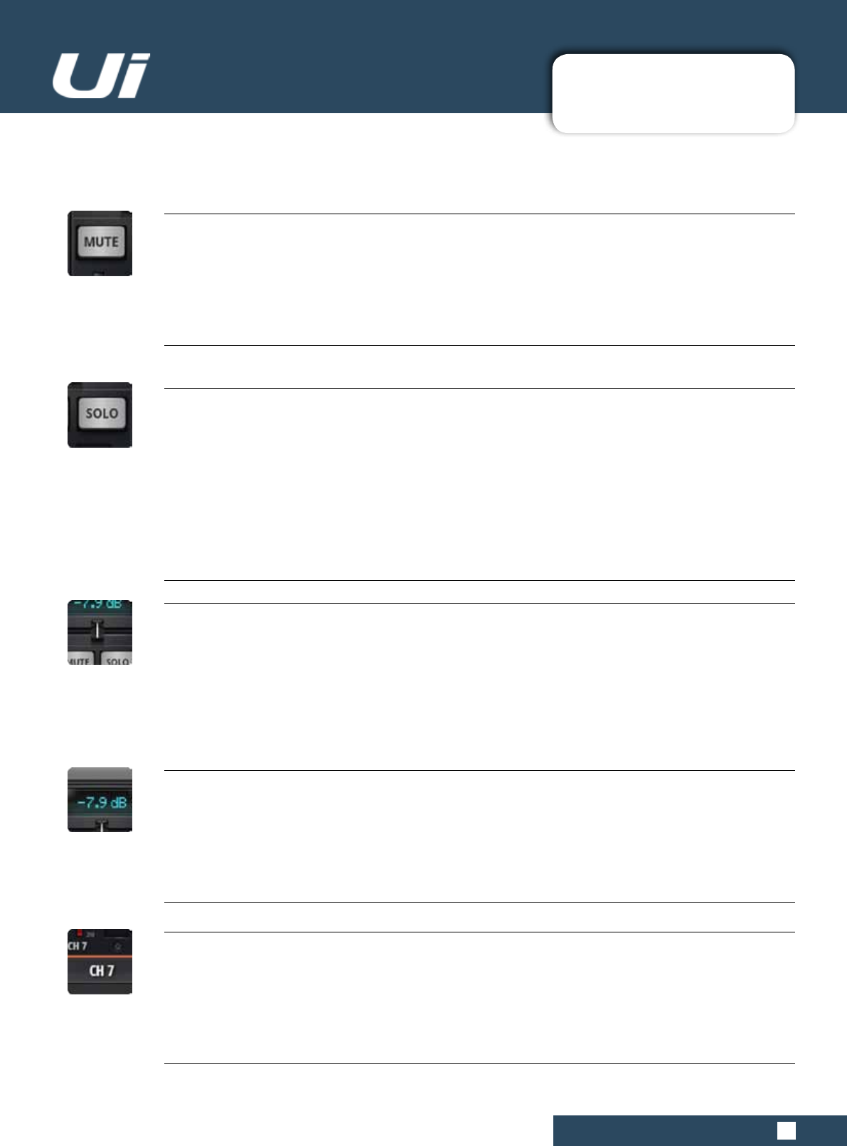
Mute and Solo buttons when acti-
vated will either Mute the channel,
removing it from the mix or Solo it
by removing all other channels.
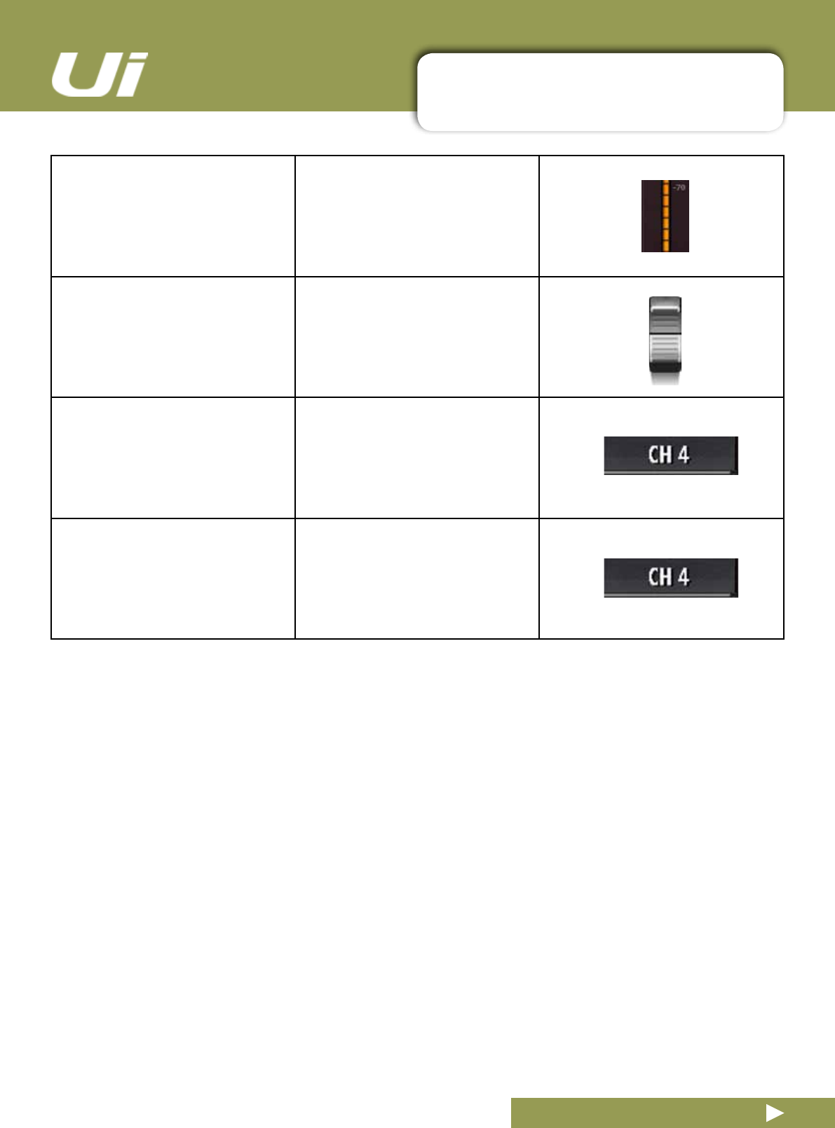
Channel Gain LED
indicators display gain
level. Peak levels are
displayed in Red.
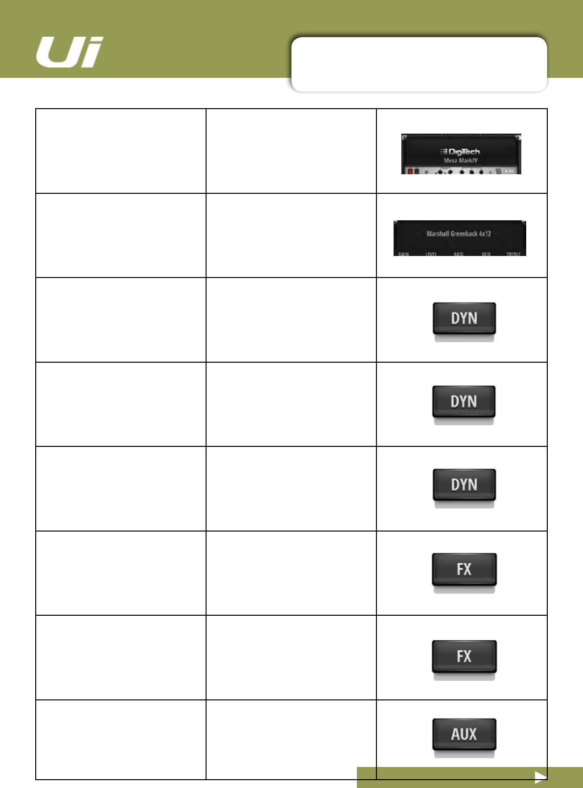
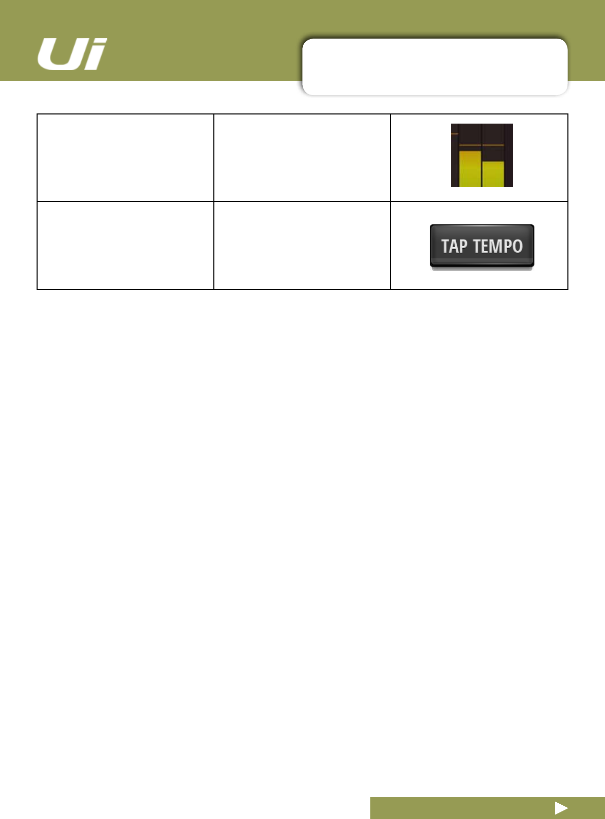
Channels can be named
by double-clicking on
the channel number
VCA group information
is displayed top LH for
multiple VCA groupings
Stereo pairing when
activated will pair two
adjacent channels and
pan them left/right
Ui24R User Manual 4.0:2 Ui SIDE PANEL
CHANNEL STRIP
4.0:2 Ui SIDE PANEL
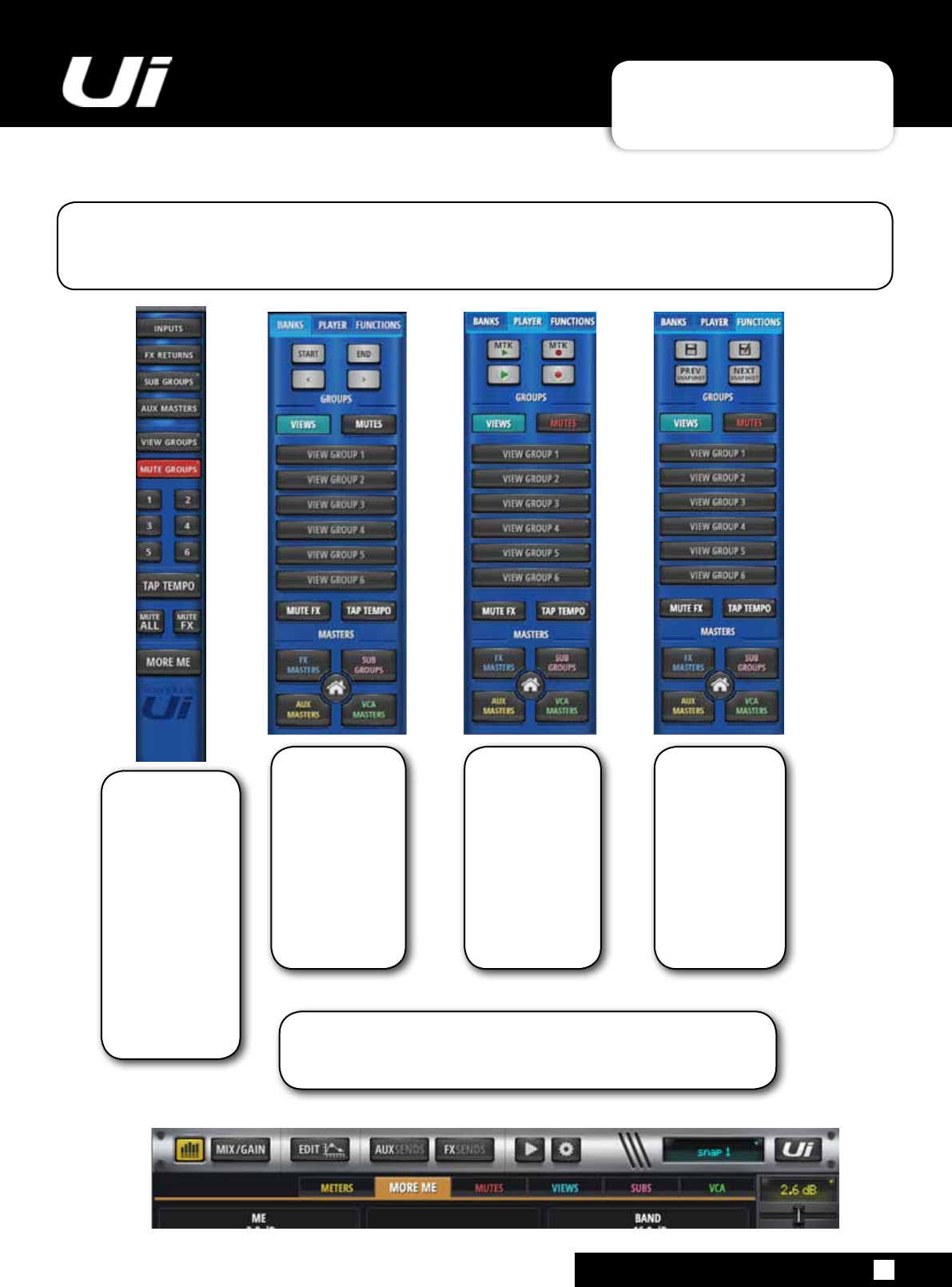
The Ui Side panel is a multi-function interface that enables easy access to View and Mute Groups. The
expanded format has separate tabs for Banks, Media Player and Functions allowing even greater ac-
cessibility.
The Large format
Slideout Ui Strip
in Banks Mode
expands on the
standard slideout
strip with Smart
Scrolling through
the Ui display and
quick tabs to trans-
port the user to the
Start or End of the
display.
The Large format
Slideout Ui Strip
in Player mode al-
lows quick access
to Muliti-track
and 2-track USB
Playback and
Recording.
The Slim Slideout
Ui Strip displays
Inputs, FX Returns,
Sub Groups, AUX
Masters, View and
Mute Group Tabs.,
Tap Tempo, Mute
All, Mute FX and
More Me options.
Clicking on these
will open their
function screens
allowing the user
quick access. All three Large format Ui Strips give easy access to View and Mute
Groups, Mute FX, Tap Tempo, FX Masters, AUX Masters, VCA
Masters and Sub Groups. The More Me function is accessed via a
tab in the Meters screen
The large format
Slideout Ui Strip
in Functions
Mode allows the
user access to
Save snapshot,
update current
snapshot, previ-
ous snapshot/
next snapshot
scrolling through
snapshots.
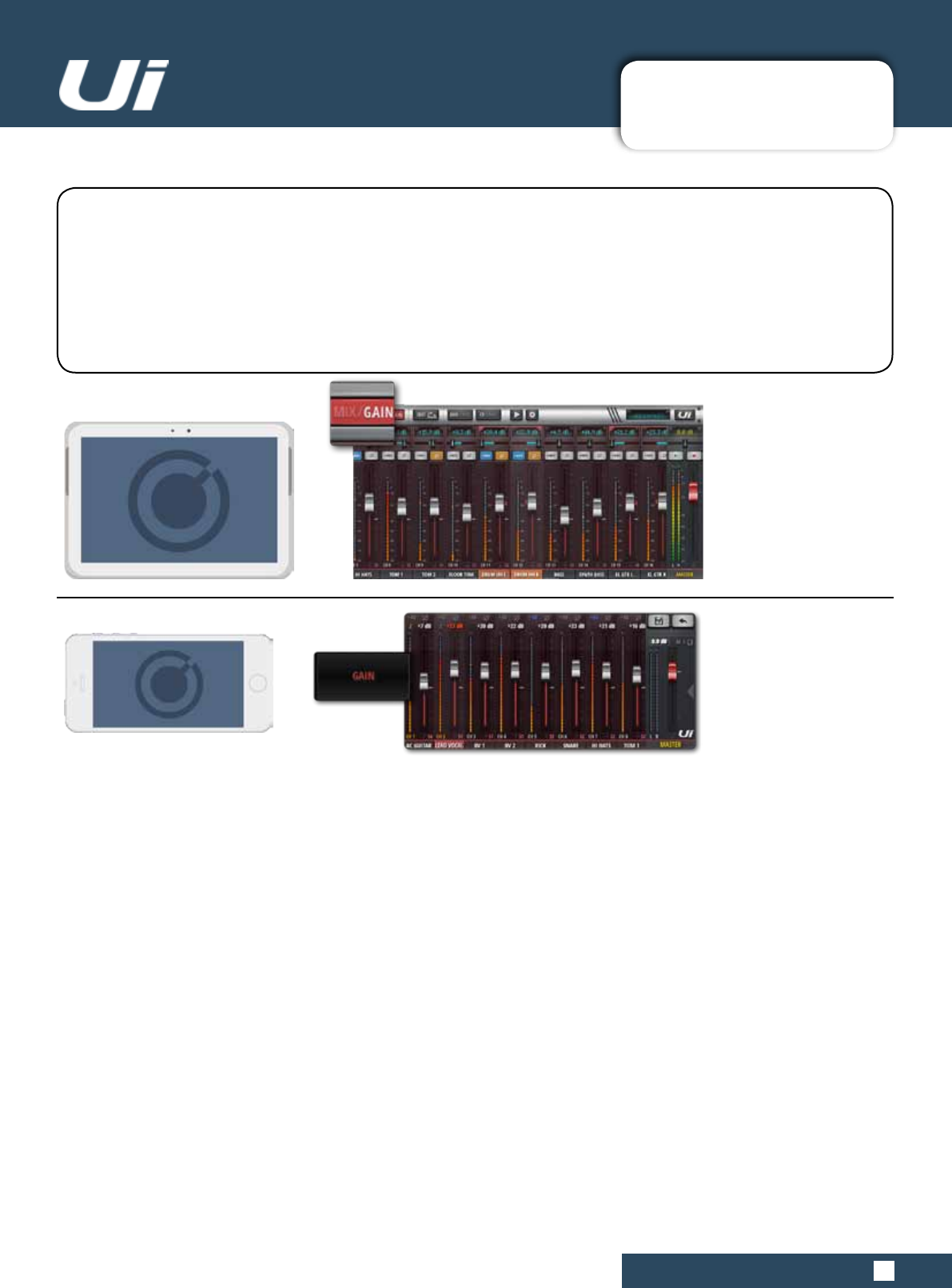
4.1: INPUT: GAIN PAGE
CHANNELS > INPUT: GAIN PAGE
4.1: INPUT: GAIN PAGE
Ui24R User Manual
The Gain page allows you to control the input stage aspects of a Ui input channel. It is a channel strip-type
display with red fader level indicators.
TABLET: Click/tap MIX/GAIN button to toggle MIX and GAIN pages.
PHONE: Use the GAIN menu button to navigate to the GAIN page.
NOTE: The GAIN screen has the Input Display and Pan/Balance controls in common with the MIX screen -
please see section 4.2 for details.
All Ui mixer models include remote gain control and remote phantom power. This great feature allows you to
change the Microphone input Gain and Phantom Power remotely on your Ui software without needing to touch
thehardware).
GAIN
Theaudioinputshaveaninputgainrangefrom-10dBupto+60dB.It’sagoodideatomakesurethegain
fader is down when plugging in new sources. Avoid ‘clipping ‘ the input - when you see the red clip light
constantly registering, the signal will be distorted. Simply reduce the gain to avoid this.
WhenyouswitchtoMIXfromGAIN,thevolumefaderschangetoGAINfaders(redlineunderneaththefader
knob).Inthetabletsoftware,theMUTEandSOLObuttonschangeto+48V(Phantompower)andϕ(Phase
Reverse)andDelaybuttons.InthephonesoftwarethosecontrolsareintheEDITpage(youcandouble-tapa
channelnametoswitchtotheEDITpagefaster).NotewhenaDAWinputisselectedtoachannelthegaincon-
trol will be moved to the DAW gain section.
4.1: INPUT: GAIN PAGE
4.1: INPUT: GAIN PAGE
Ui24R User Manual
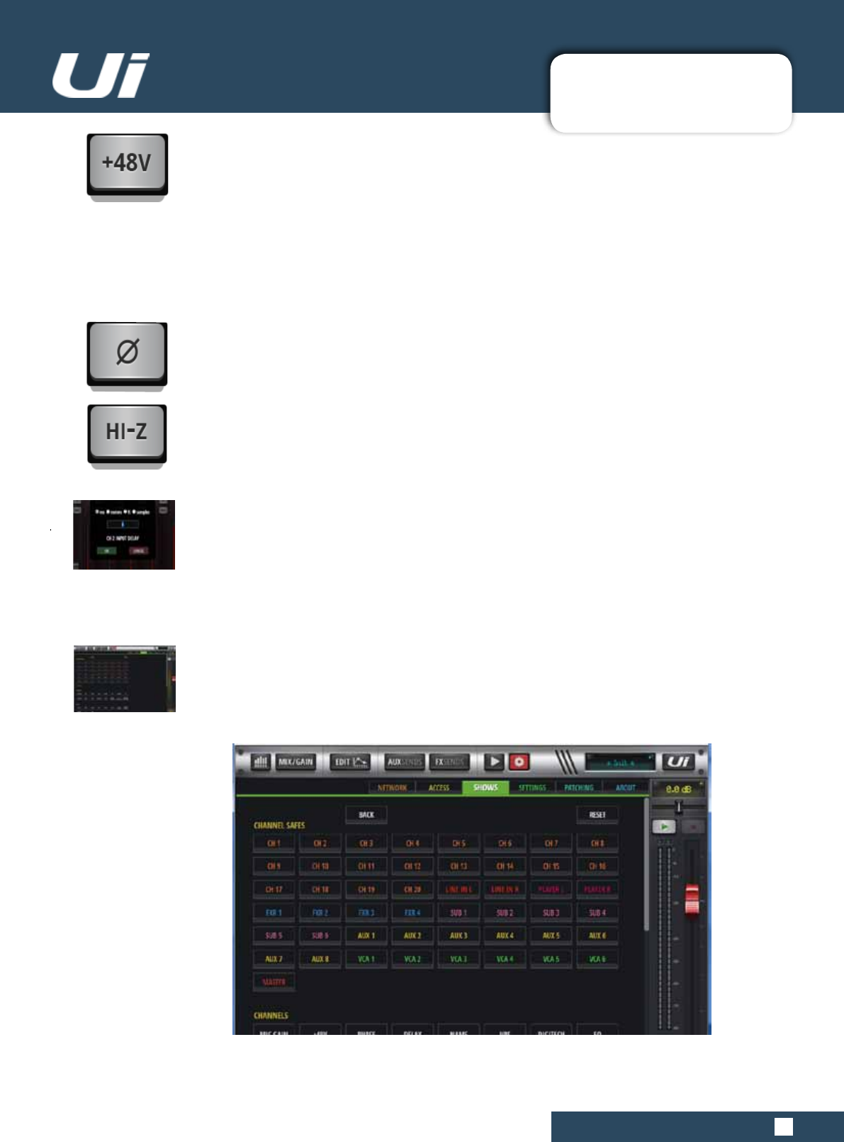
PHANTOM POWER
Phantom Power is required to power certain microphones such as condenser microphones,
or other active
devices such as an active DI. It is activated per channel. You can get an overview of phan-
tompowerstatusintheMETERSscreen(blueindicator).
When phantom power is activated, the channel output is momentarily muted to avoid tran-
sients being
transmittedtotherestoftheaudiochain(protectingyourPAspeakers).
PHASE REVERSE
Reversing the phase can help eliminate unwanted frequencies that may result in feedback
orsimplyhelpcorrectthesoundwhenitsounds‘outofphase’ornotquiteright.
HI-Z (Only available on CH1 and CH2)
Highvoltage,Lowcurrentsourceslikeguitars,keyboardsandbasseswillbenetfromusing
the Hi-Z input on CH1 and CH2.
INPUT DELAY
The Input delay can be varied from 1-250ms. This will enable the user to allow for different
microphone placements on a large stage for example. By delaying the input signals form
various sources, the user can create a more coherent mix.
Enter the GAIN tab. Each input fader bay will offer a delay button. When pressed a delay
entry modal will open allowing user input of selected delay value.
The user enters a delay value in ms, meters, ft, or samples.
ISOLATE
Isolate channel parameters from changing with show or snapshot revisions. This protects
the parameter from being overridden by snapshot changes.
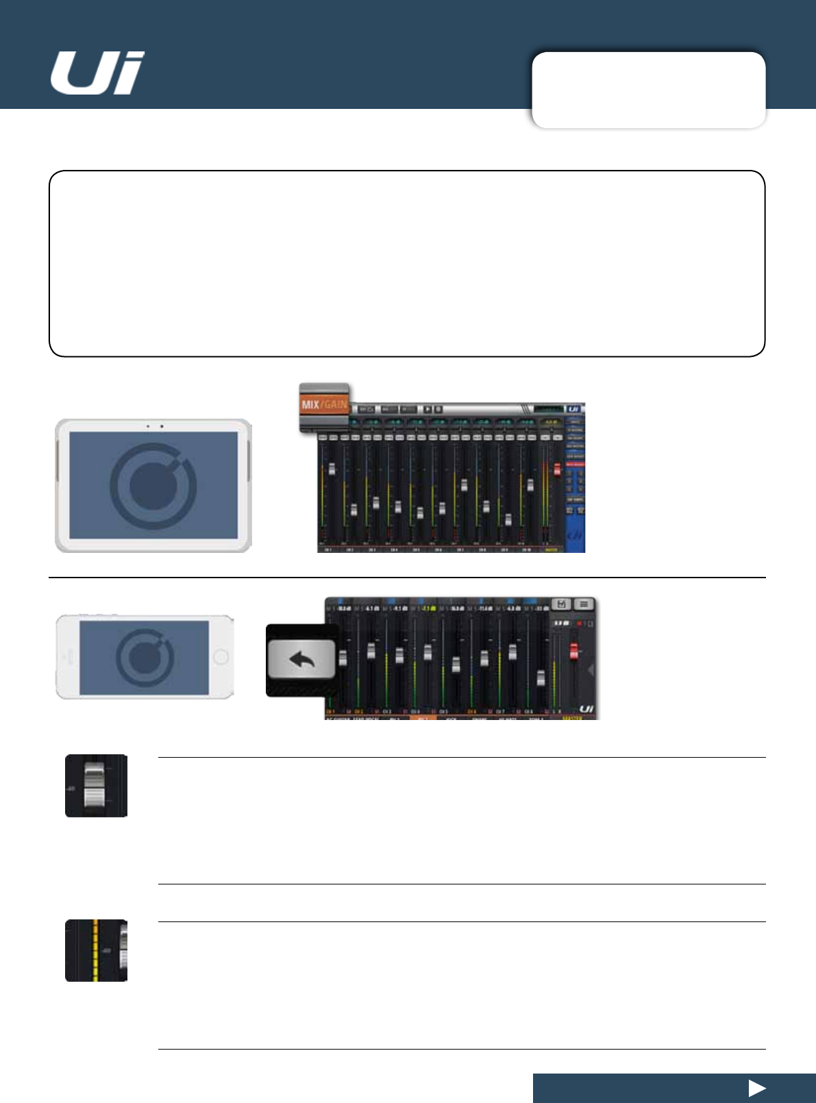
4.2: INPUT: MIX PAGE
CHANNELS > INPUT: MIX PAGE
4.2: INPUT: MIX PAGE
Ui24R User Manual
TheMIXpageistheUicontrolsoftware’sdefaultpageandallowsyoutocontroltheroutingandpanning
and fader of a Ui input channel. Please note - the phone software displays panning/balance, solo, and mute
status, but for control you should use the EDIT page. Those controls are described in this section.
TABLET: Click/tap MIX/GAIN button to toggle MIX and GAIN pages.
PHONE: The RETURN button will always return you to the MIX page.
Adoubleclick/taponaGAINchannelstrip(notthefadercap)willreturnyoutotheMIXpage.
A double click/tap on a channel name will take you to the EDIT page for that channel.
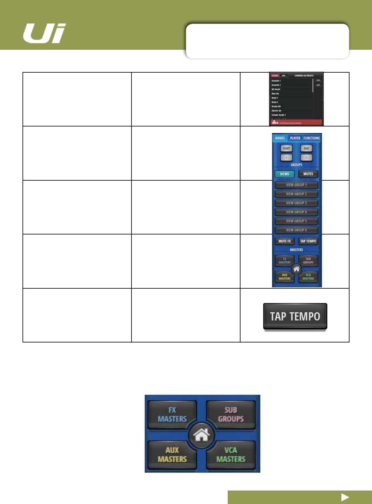
FADER
Adjust the level of this channel in the master stereo mix.
METERING
VU metering for input level and volume level.
TheVUmetersontheMIXpageshowtwocolours.Thebluemetersshowtheinputgain(fromtheGAIN
page)andtheyellowmetersoverthetopshowthevolumelevel.Pleasenote,EQ&DYNaffectsthevolume
meters.
4.2: INPUT: MIX PAGE
CHANNELS > INPUT: GAIN PAGE
4.2: INPUT: MIX PAGE
Ui24R User Manual
MUTE
Turn off the audio signal of a channel
MUTEisanimmediateaudiooff,ratherthanhavingtoslidedownthefader(andremovesthepossibilityof
forgettingitsoriginalposition).TheMUTEbuttonmutesthechanneloutputtothemainstereobus.Itcan
alsomuteanauxoutput,dependingontheaux’sPREorPOSTstatus(postfaderauxwillbemuted).
SOLO
Solo this channel
The SOLO button is grey when not in use and yellow when operational. Press the SOLO button to only hear
the Soloed channel. In SETTINGS the SOLO button signal can be routed to the headphones or to the Mas-
teroutputs+headphones.Therearealsotwosolomodes:SOLO1(pressingaSOLObuttondeactivates
aprevioussolo)andSOLO+(solosarecumulativeanddonotcancelprevioussolos).NOTE:Ifthe‘AUX’
optionissetfortheHEADPHONESOUTparameter(SETTINGS),theheadphonesoutputwillnotreectthe
Solo selection.
Thedefaultroutingis‘PFL’(PreFadeListen.However,SoloscanbesettoAFL(AfterFaderListen)inthe
SOLOTYPEparameterinGLOBALSETTINGS(seesection10).
PAN / BALANCE
Adjust the Pan / Balance
CHANNEL DISPLAY
Numeric fader level and pan
Shows the input as a dB level. It also shows the Pan position for three seconds after the pan slider is
moved.
CHANNEL NAME
Channel sub menu access, channel name scrolling, channel select
The Channel Name is usually a name/description of that channel. You can click on channel names to select
that channel, double click/tap a channel name to go to the EDIT screen for that channel, or you can Long-
Click/Taponachannelnametoaccessthechannelsub-menu(Seesection4.3).
4.2.1: INPUT SUB-MENU
CHANNELS>INPUTSUB-MENU(AddVCAafterAssignSubGrouponimagegrab)
4.2.1: INPUT SUB-MENU
Ui24R User Manual
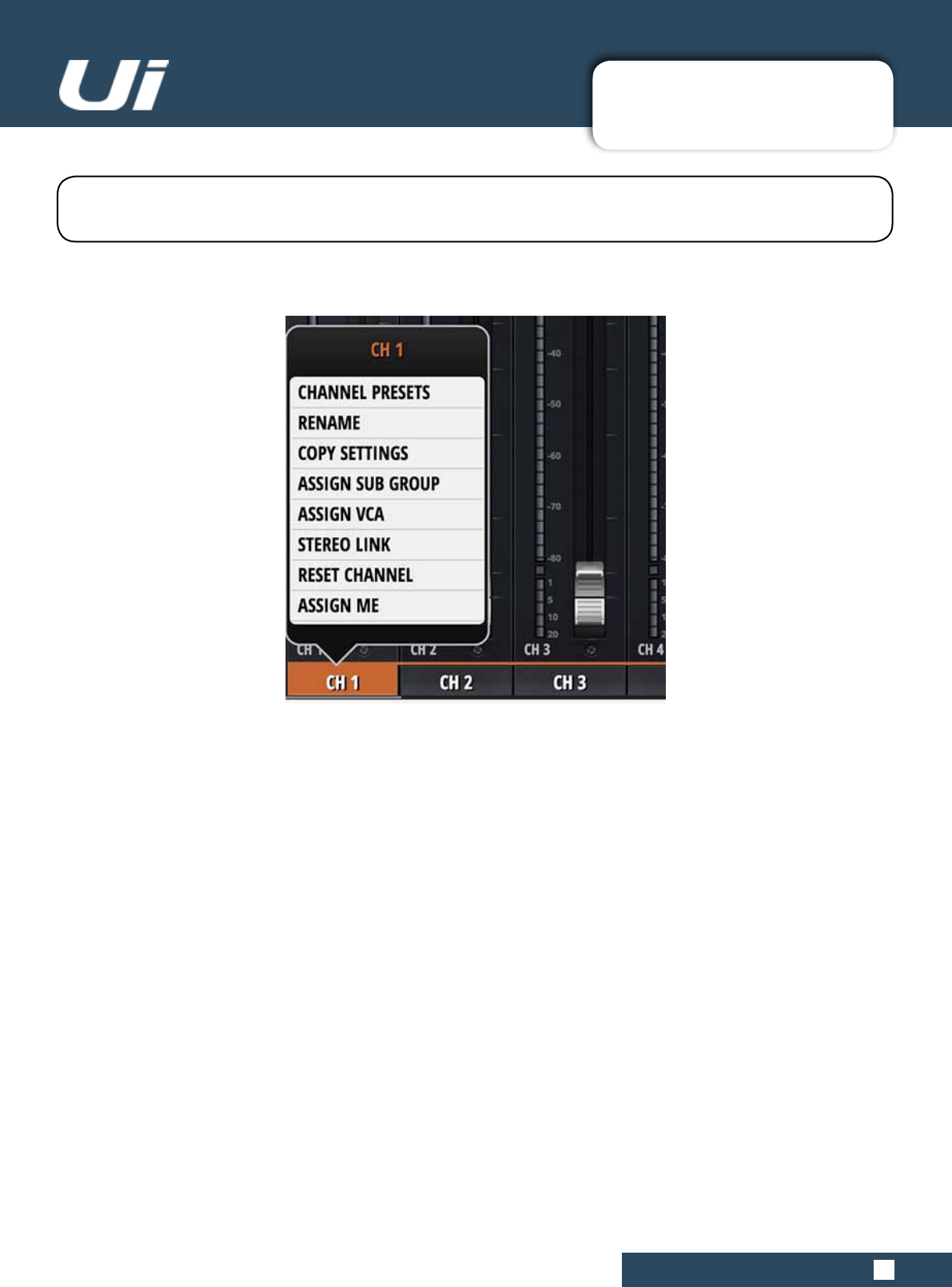
By long-clicking/tapping on a channel name you can access the channel sub-menu for access to various
channel parameters...
CHANNEL PRESETS
Recall and save whole channel settings - Factory and User preset banks.
RENAME
Renamethechannel.ThenewnamewillbeshownintheChannelNameelds.
COPY / PASTE SETTINGS
Copythechannelsettingstothepasteboard.A‘PASTESETTINGS’optionwillappearwhenyouselectanother
input channel sub menu. Use that to paste the copied settings to that channel.
ASSIGN SUB GROUP
Choose a sub group for this channel. For example, you might want to assign all drum kit microphones to a ‘Drum
Kit’subgroup.Onceassigned,thesubgroupassignmentgridwillbereplacedwithan‘UNASSIGN
SUBGROUP’option.
4.2.2: VCA GROUPS
4.2.2: VCA GROUPS
Ui24R User Manual
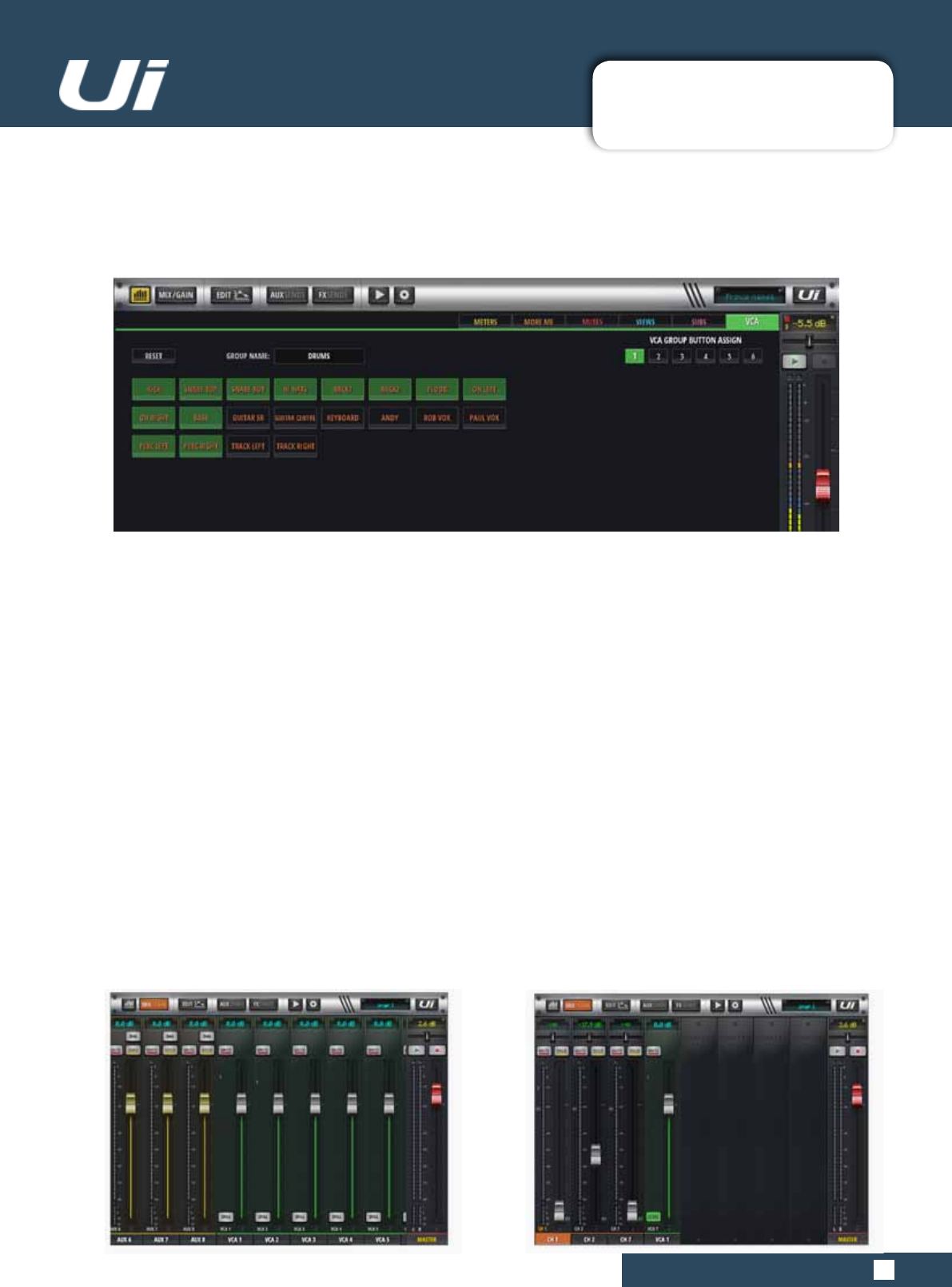
HOW TO ADD/REMOVE MEMBER CHANNELS
VCA channels are assigned via the pop menu accessible by holding down on the desiired channel. All
changes can be made through this menu.
VCA INDICATORS ON CHANNEL STRIP
Color indicator for channel virtual LCD panel turns green when VCA is engaged for that channel. Also the chan-
nel strip will display V1-6 in green depending on which VCA is engaged.
VCA MUTE
When mute is placed on a VCA master, all member channels are also muted.
STEREO LINK
Createandstereochannelfromtwomonochannels.Odd/even(L/R)pairsarelinked,soifyoulinkchannel2
(right),itwillcreateastereochannelwithchannel1(left).
RESET CHANNEL
Reset channel sends a channel back to its default setting.
VCA SPILL
By clicking on the Spill tab on the VCA channel strip, the user can expand the entire VCA spread for that
channel.
ASSIGN VCA
VCA Groups allow you to control groups of Input Channels from a single VCA Master. For example, you could
put the whole drum kit under the control of a single VCA Master, or if you have a multiple mics on a guitar cabi-
net you could set the ratios with individual channels and then create a Guitar VCA Master - move the VCA Mas-
terChannelandallGroupMemberlevelswillbe‘offset’fromcurrentlevelsbytheVCAMasterlevel.TheUi24R
isabletoassignVCA’sfromtheMETERSSubMenuorfromindividualChannelSub-Menu’s.
4.2.3: MATRIX
4.2.3: MATRIX
Ui24R User Manual
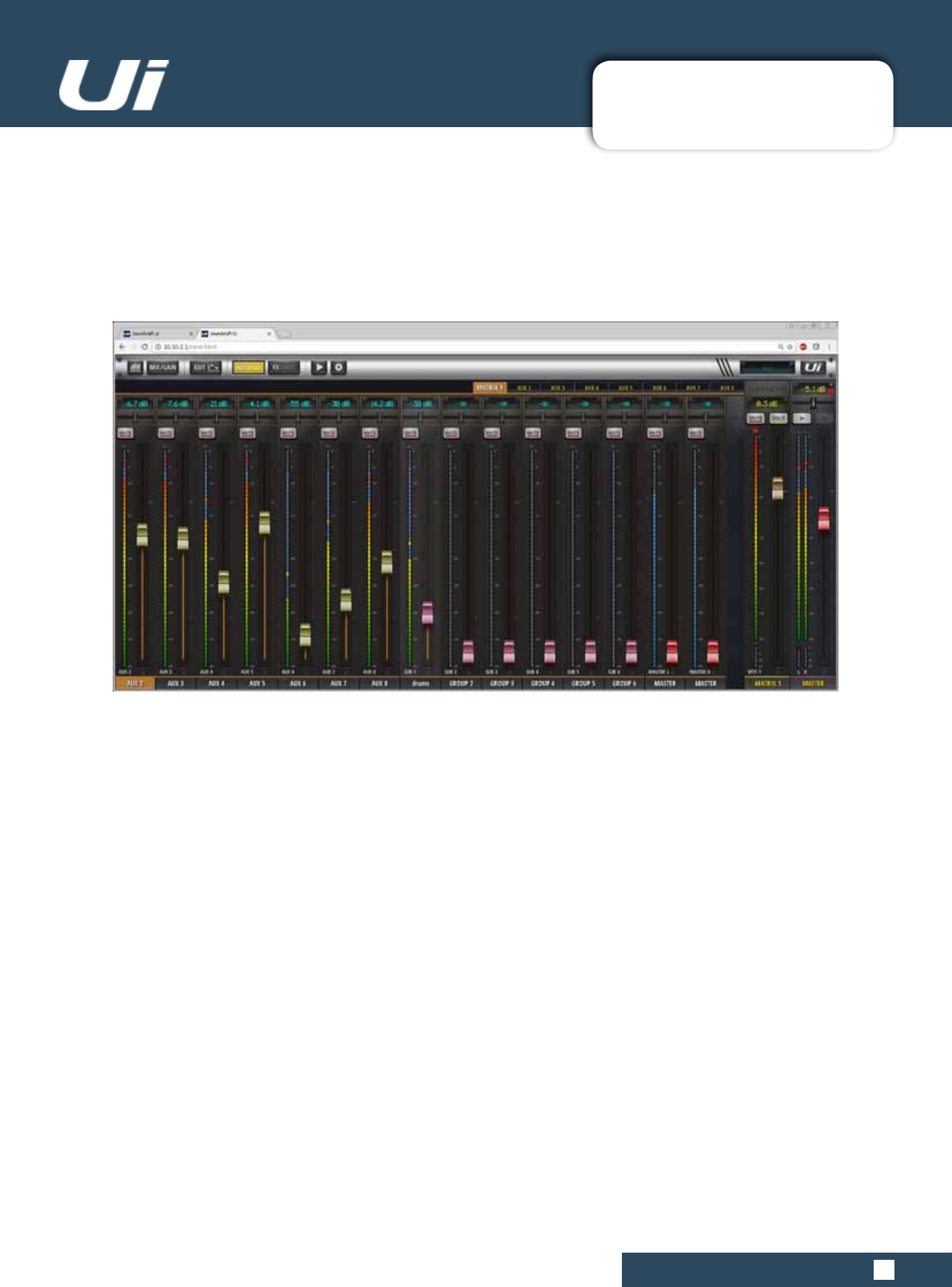
MATRIX CONTRIBUTIONS
Matrix Contributions can come from:
AUX Sends
Sub Groups
MasterL/R(canbePre/Postfader)
NotethatXLRoutputs1/2whichareautomaticallyassignedtoAUX1/2orMatrix1/2haveHPFandLPFlters
which can be used as crossovers.
MATRIX
A Matrix can best be described as a mixer inside the mixer. In its most simple form, a matrix takes a selec-
tionofinputs(usuallyderivedfromthegroupandmainoutputbuses)andallowsroutingofthosesignals,
complete with level control, to a series of outputs.
Matrix systems offer the ability to choose from a variety of inputs including external sources, and offer sig-
nal processing including EQ, compression, noise gate and delay/reverb. Contributions stuff

4.2.4: METERS
4.2.4: METERS
Ui24R User Manual
METERS
The Meters page displays all active channels meter readings along with indicators for Mute, Solo,
Phantom 48v power and Phase Reverse.
Users can click on any channel meter and they will be brought to directly to that channel. Alterna-
tively, double clicking in an input channel will bring the user back to the Meters page.
Color coded indicators
for 48v Phantom power,
Inverse, Mute and Solo.
At a glance the user can
keep an eye on peak
levels for all channels
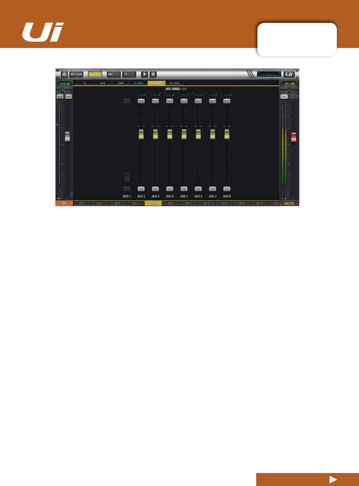
4.3: AUX SENDS
CHANNELS > AUX SENDS
4.3: AUX SENDS
Ui24R User Manual
AuxOutputs(shortforAuxiliary)aretheoutputsonthetoprightoftheUihardware.Theseoutputseach
have their own mix of input sources, separate from the master mix. Generally, aux outputs are used for
musicianstoheartheirownmixonstageviaastagemonitorspeakerortoheadphoneampliersforin-ear
monitoring. Alternatively, the aux outputs can be sent to external hardware FX units.
AUX SENDS is where the aux mixes are created - these can be for monitor outputs, for external FX sends, and
more. They have dedicated outputs on the Ui hardware. The aux faders have orange level indicator lines and
determine how much of each input channel is contributed to the Aux bus. Ui24R has 8 main Aux busses
available.Youcanviewallauxcontributionsfromasinglechannelbynavigatingtothatchannel’sEDITpageand
selecting the AUX SENDS screen / tab.
SelecttheAUXtabyouwishtomix(AUX1toAUX8),andthenadjustthechannelvolumes(contributionsfrom
inputchannels).TheAUXSENDfaderontheright(orangefader)istheAuxMasterchannelfader-the
overall output volume for your AUX mix.
Aux Master channel faders can be viewed together either with the AUX MASTERS button in the Tablet version
Slideout panel, or from the JUMP TO option in the phone software slideout panel. You can also scrolling to the
right-handendoftheMixpagechannels.AuxMasterchannelscanberenamedandstereo-linked(seebelow).
STEREO AUX
Stereo-linking channels is possible for both the input channel sends and the Aux Masters. To stereo link Auxes,
usetheAuxMasterchannelsub-menu(long-click/taponthechannelname).
Gotothechannelpop-upmenu(longclickchannelname)toaccesstheStereoLinkfeature.When2monoinput
channels are stereo-linked on the main MIX page, those channels will also be stereo-linked on the AUX SENDS
page.(2channelspannedleft&rightwithagreenlinklineabovethedBdisplay).
FX ON AUX
It is possible to send FX to your aux mix. Scroll to the end of the channel list and you will see the FX RETURN
faders.When adding the FX you are adding a global FX signal from the main mix.
4.3: AUX SENDS
CHANNELS > AUX SENDS
4.3: AUX SENDS
Ui24R User Manual
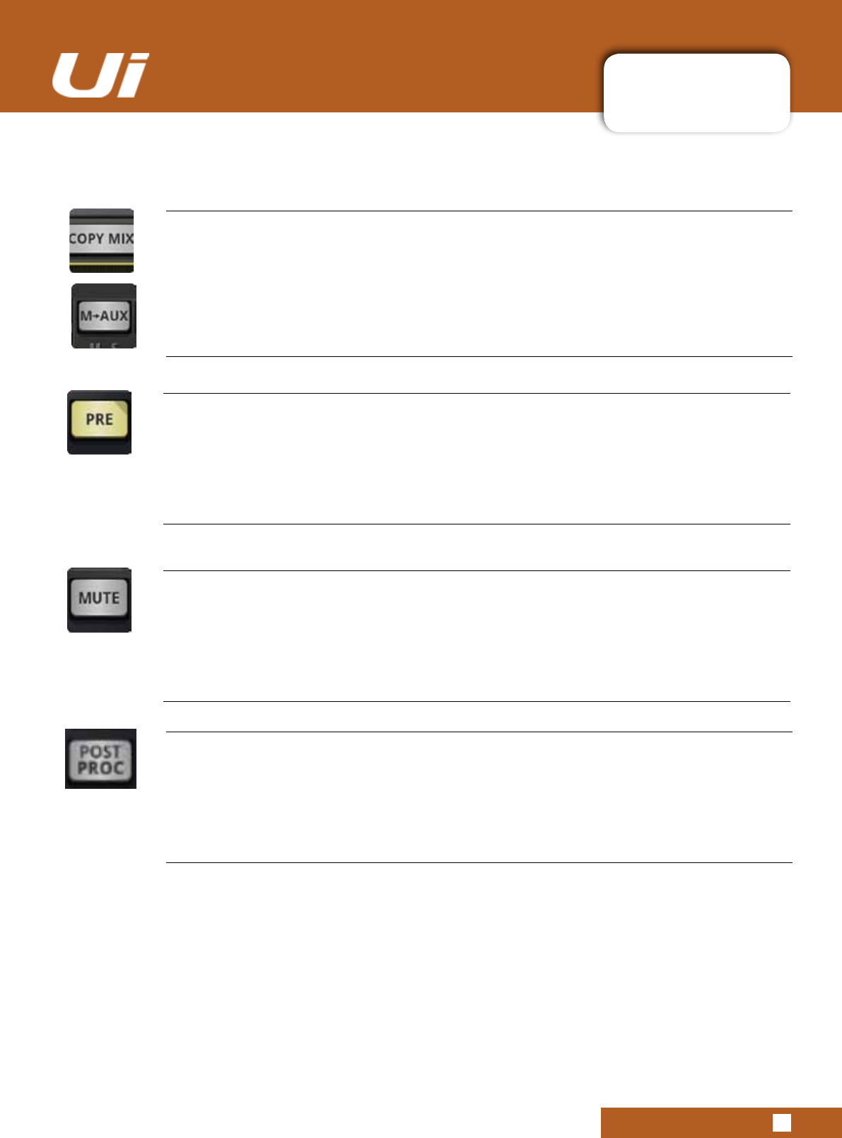
PRE/POST (Tablet software)
Switchinputchannel’sAuxcontributionbetweenPREandPOSTsources
AUX channels are pre-fader by default, meaning the volume faders on the MIX page do not affect the aux
levels. Press the PRE button to change individual channels to POST fader. A long press on the PRE/POST
button opens a dialog for ALL CHANNELS TO PRE or POST.
AUX SEND MUTE (Tablet software)
Mutetheinputchannel’scontributiontothisauxmix.
Separate to the normal input channel mute - only affects contribution to the selected aux mix.
M-AUX / COPY MIX
Copy the main mix to this aux mix
This button copies the fader positions from the MIX page and moves all aux send faders to the same posi-
tion on the AUX SENDS page. This is a handy starting point for an AUX mix rather than starting from all
faders down.
You can press this button at any time if you want your monitor mix fader positions to resemble the MAIN mix.
Forsafety,userconrmationisrequired.
PRE/POST PROCESSING
Allows for selection for pre or post processing of the channel to be sent to the aux mix
4.3: AUX SENDS
CHANNELS > AUX POP MENU
4.3: AUX SENDS
Ui24R User Manual
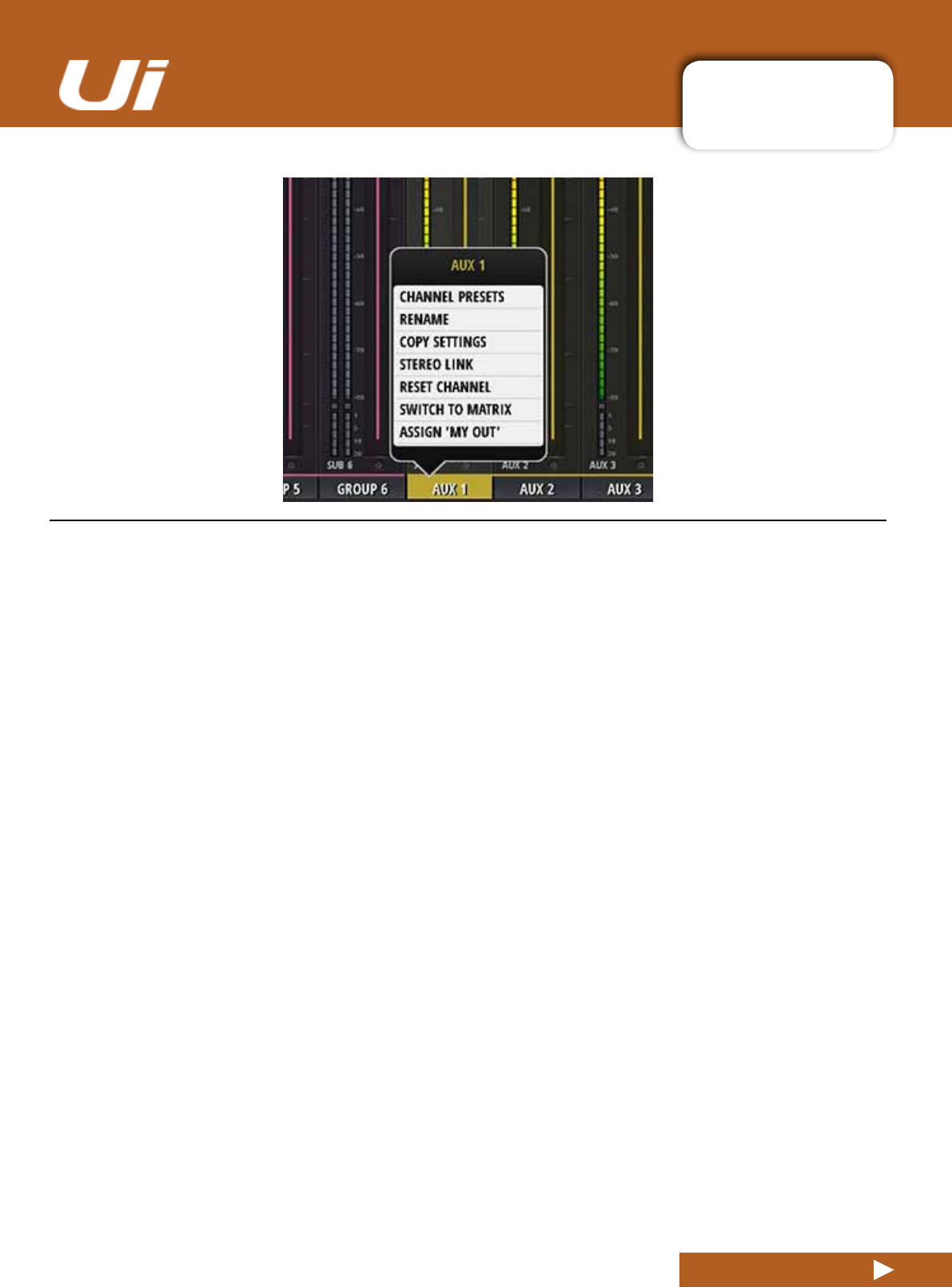
CHANNEL PRESETS
Recall and save whole AUX channel settings - Factory and User preset banks.
RENAME
RenametheAUXchannel.ThenewnamewillbeshownintheAUXNameelds.
COPY / PASTE SETTINGS
CopytheAUXchannelsettingstothepasteboard.A‘PASTESETTINGS’optionwillappearwhenyouselect
another AUX channel sub menu. Use that to paste the copied settings to that AUX channel.
STEREO LINK
Link two AUX channels in Stereo. Left and Right channels will automatically pan hard Left and Right.
RESET CHANNEL
Resets channel to default setting.
SWITCH TO MATRIX
Switch selected AUX channel to Matrix mode.
AUX mode channel contributions to output > All input channels inc line in, Player and FX Masters
Matrix Mode> AUX, Subgroups and Master Left/Right
ASSIGN MY OUT
AUXchannelscanbeassignedasyourpersonalmonitoror“MYOUT”fromthechannelpopmenu.Only
one“MYOUT”canbeassignedperuserbutindividualuserscanhavedifferentAUXchannelssetastheir
personal“MyOUT”.‘MYOUT”willalsoworkforstereolinkedchannelswhichisperfectforIEMs.
4.3: AUX SENDS
CHANNELS > AUX SENDS
4.3: AUX SENDS
Ui24R User Manual
AUX SENDS
InChanneleditmodetheAUXSendstabwillshowtheselectedChannelssendstoallAUX’screatingan
alternate Channel based AUX view.
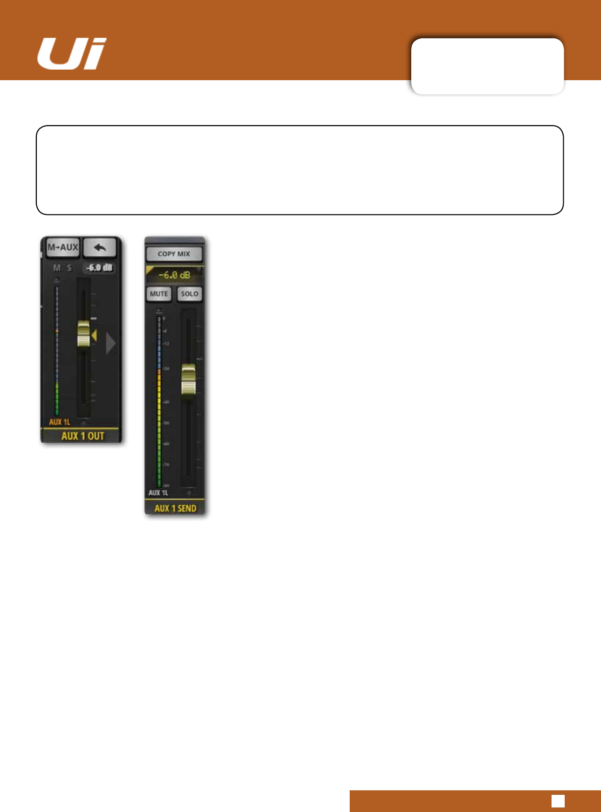
4.3.1: AUX MASTER
CHANNELS > AUX MASTER CHANNEL
4.3.1: AUX MASTER CHANNEL
Ui24R User Manual
The Aux Master channel is the output path for Aux busses. In other words, the Aux 1 mix of contribu-
tions from all input channels passes through the Aux 1 Master channel before being sent out of the
physical Aux 1 output. Ui24R has four Aux busses available, and Ui24R has six. The highest-num-
beredauxpairs(3/4forUi24Rand5/6forUi24R)areavailableasphysicaloutputswhentheHEAD-
PHONESOUToptionissetto‘AUX’inSETTINGS
Aux Master channels have their own EDIT channels, featuring a
GEQ(GraphicEQ)ratherthanaparametricEQ,anddbxAFS2
feedbackelimination(Seesection5).
You can view all Aux Master channels either in the MIX screen
(scrolltoright)tobyselectingAUXMASTERSfromthetablet
software Slideout panel or from the JUMP TO pop-up menu in
the phone software Slideout panel.
PHONE
TABLET
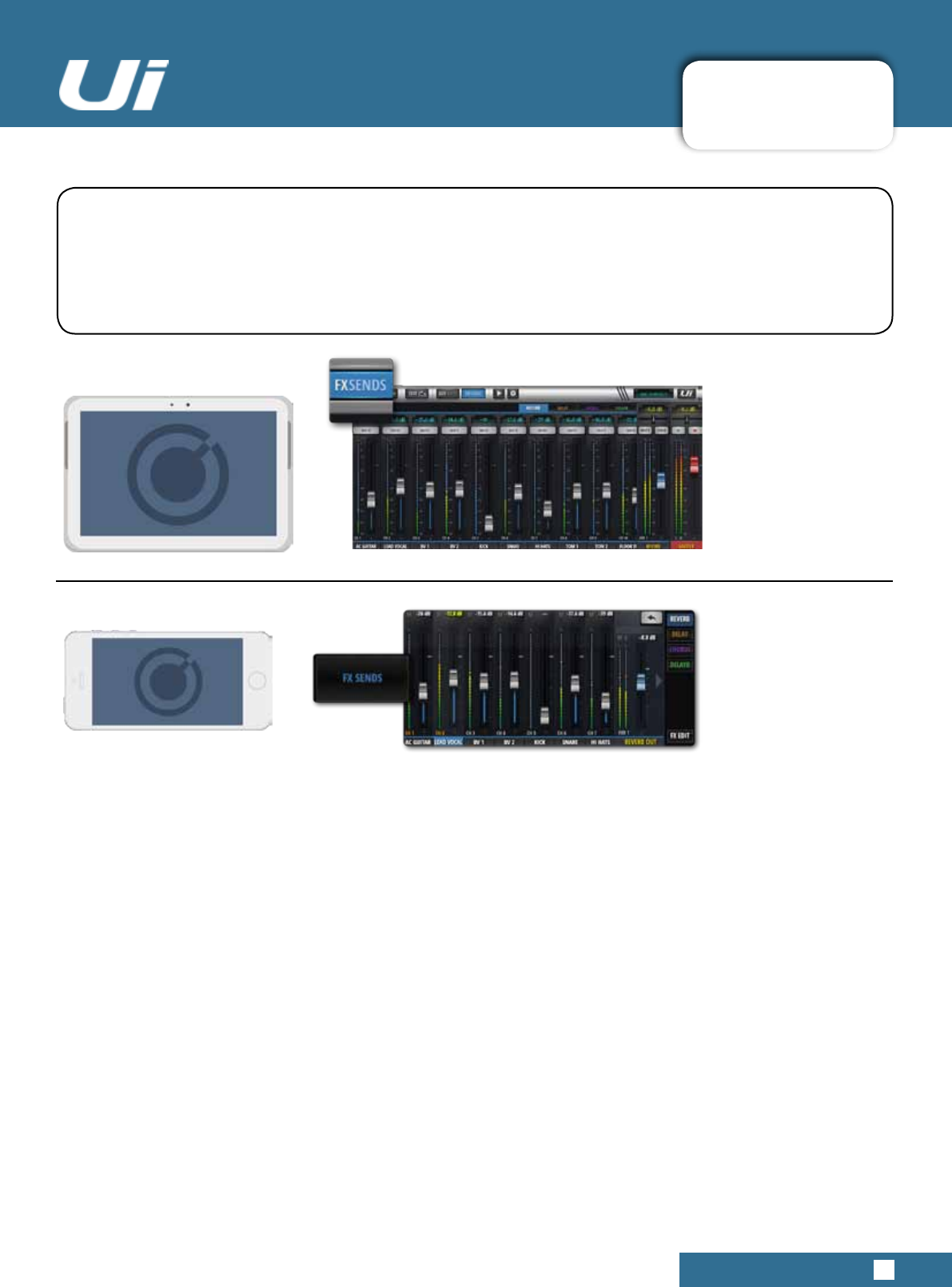
4.4: FX SENDS
CHANNELS > FX SENDS
4.4: FX SENDS
Ui24R User Manual
FXSENDSfaderseffectivelydeterminetheamountofeffect(delay,reverb,chorus)oneachinputchannel.
They work much like aux sends in that a mix of input channel contributions is created on the FX SENDS
page - one for each FX processor. After processing, that mix is returned via its own FX Return channel,
whichworksjustlikeaninputchannel-adjustingtheoveralllevelofthatprocessor’smixinthemaster
stereo mix. The FX Return channel for the selected FX processor is shown in the FX SENDS view, next to
the Master Channel.
All FX Return channels can be viewed either by scrolling in the main MIX view, by choosing FX RETURNS from
the Slideout panel in the tablet software, or from the JUMP TO option in the phone software Slideout panel.
YoucanviewallFXcontributionsfromasinglechannelbynavigatingtothatchannel’sEDITpageandselecting
the AUX SENDS screen / tab.
IntheFXSENDSpage,rstselectwhicheffectyouwishtoadjustusingthetabs.Adjustthegreyfadersto
increase or decrease the contribution of that channel to the selected FX processor. Adjust the blue FX RETURN
fader labelled FXR 1 REVERB to control the total amount of REVERB heard in the mix.
Input channel FX Sends can be individually muted in the FX SENDS page.
NOTE: FX sends are POST FADER, meaning a change of level on the main mix page affects the level
sent to the FX processor. This ensures that each input channel’s contribution to the FX send is always
proportional to its prominence in the main mix.
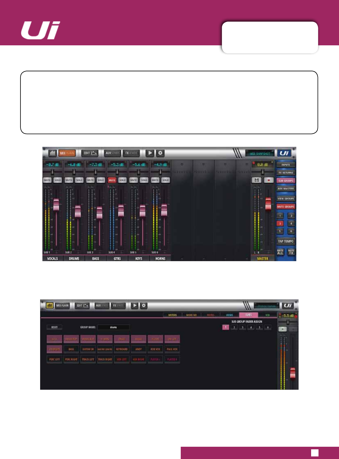
4.5: SUB GROUP MASTER
CHANNELS>SUBGROUPMASTERCHANNEL(4xSubGroups)
4.5: SUB GROUP MASTER CHANNEL
Ui24R User Manual
If you want to have control over the drum kit mix, for example, but also want single fader control over the
wholekit’scontributiontothemix,youwoulduseaSubGroup.
When input channels are allocated to Sub Groups, either via the input channel sub-menu, or via the SUBS
screen in the DASHBOARD/METERS page, they are mixed together into a single stereo channel.
Sub Group Master channels have their own EDIT channels, as per any other Ui input channel.
ASSIGN SUB GROUPS
Sub Groups are assigned within METERS>SUBS
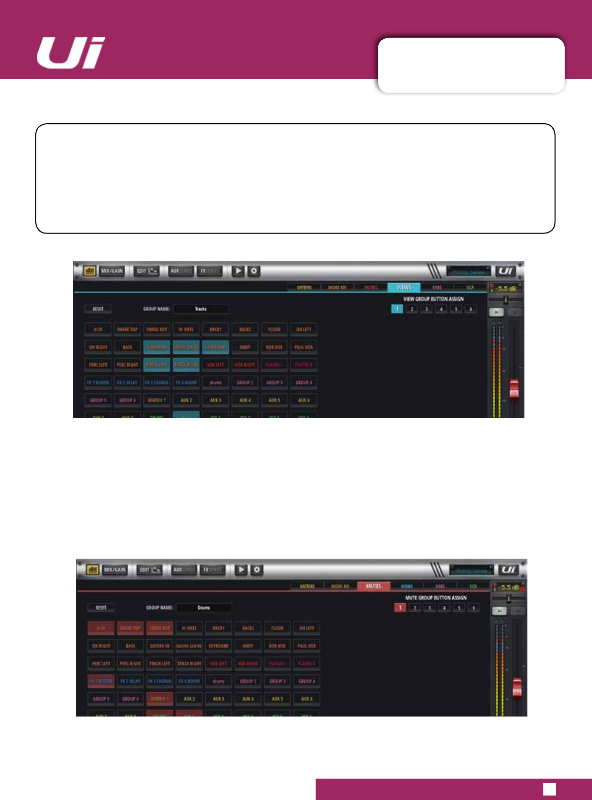
4.5.1: VIEW/MUTE GROUPS
CHANNELS > VIEW & MUTE GROUPS
4.5.1: VIEW/MUTE GROUPS
Ui24R User Manual
VIEW & MUTE GROUPS
There are 6 View and 6 Mute groups available for users on the Ui24R. These can be navigated to via
the Ui24R sidebar. Users can name the group, set the group number and elements of the group with this
screen.
MUTE GROUPS
VIEW GROUPS
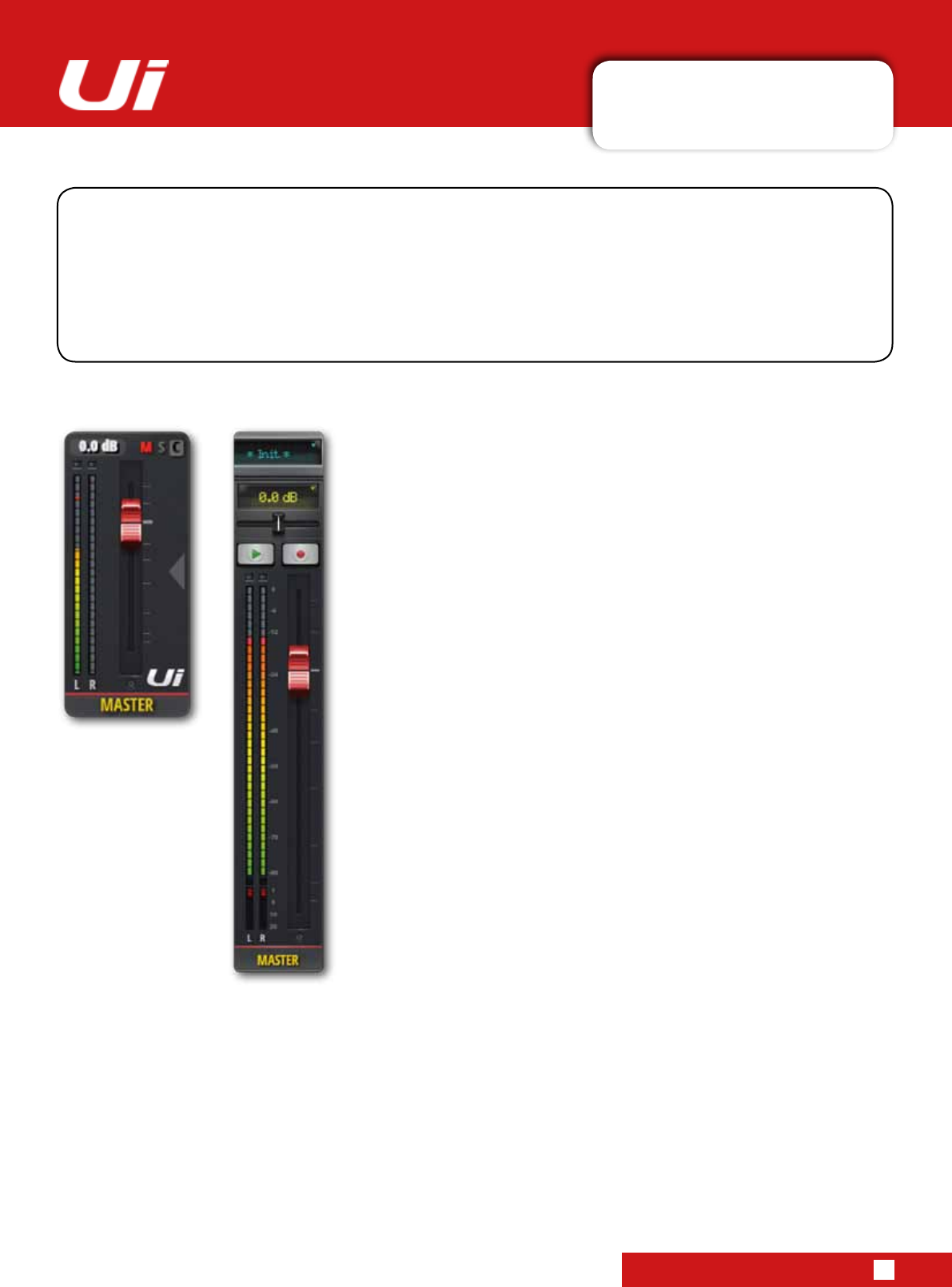
4.6: MASTER CHANNEL
CHANNELS > MASTER CHANNEL
4.6: MASTER CHANNEL
Ui24R User Manual
TheMasterStereoChannelistheoutputchannelforthemainstereo(left&right)mix-determinedbythe
input channel and FX Return channel faders and pan/balance controls. The Master Channel has its own
EDITpagetabs,justlikeotherchannels(seesection5).TheEQforUiOutputchannels(includingAux
Masters)isaGraphicEQ(GEQ)ratherthanaparametricEQ(inputchannelsandsubgroupmasters).
TheMasterFader(redfaderknob)controlstheoveralloutputvolumeofyourmixer.Theactuallevelsetby
thefaderisshowninthetopdisplayabovethefaderindB(decibels).
Display & Indicators
As well as dB, this display also has 3 useful indicators:
CLIP (C)
Notiesyouofanyinputgainclipping.Whenaninputchannelsignal
is too hot and likely to be distorting, press this display to jump to the
DASHBOARD page. In DASHBOARD, press the word GAIN in the
top right corner of the bank that is clipping, then reduce the channel
GAIN fader.
MUTE (M)
This indicates that a channel is muted. Press the display to see the
DASHBOARD overview where all mutes are viewable.
SOLO (S)
This indicates that a channel is in solo mode. Press the display to
see the DASHBOARD overview where all SOLOS are viewable.
BALANCE (Tablet Software)
The horizontal Balance fader allows the volume of left and right
to be increased or decreased, but the mix of left and right is un-
changed. Double press the balance slider to return it to the centre
position. To adjust balance in Phone Software, double tap the
Master Channel name to access its EDIT page.
F1 & F2 Buttons (Tablet Software)
ThepictureshowsF1andF2setasPLAYandRECORD(Ui24R).
F1 and F2 are programmable buttons that can be used for multiple
options. These options are selectable in SETTINGS > CONFIGU-
RATION. The options are: New Snapshot, Update Current Snap-
shot,Play,Record(Ui24RlatestFirmware,Ui24R).
If Record is selected, press record to start recording directly to your
USB stick. The REC button will highlight in red. You must have a
USB stick mounted to make a recording.
DIM
WhenshowntheDIMbuttonwillDIM(reduce)theoutputlevelby
20dB, this is generally used when monitoring in the Studio.
PHONE
TABLET
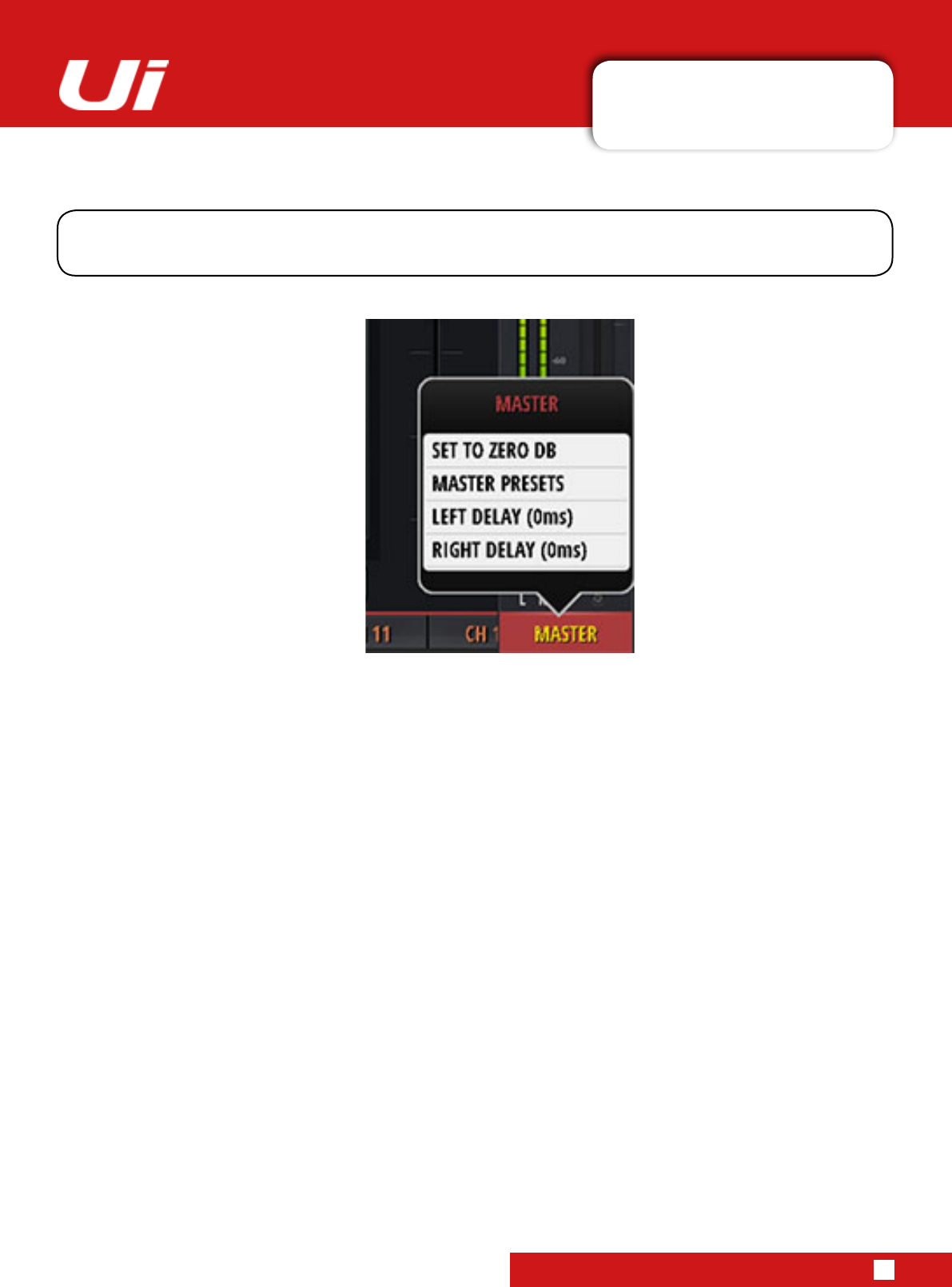
4.6.1: MASTER SUB-MENU
CHANNELS > MASTER CHANNEL > SUB MENU
4.6.1: MASTER CHANNEL SUB-MENU
Ui24R User Manual
SET TO ZERO DB
This is a fast way to set the channel fader level back to zero dB. Click and Hold the MASTER channel name,
then touch SET TO ZERO DB.
MASTER PRESETS
SaveMasterChannelsetupsaspresets.Usefulforbuildingupalibraryofnal-stageprocessingset-ups.
LEFT DELAY/RIGHT DELAY
Delay can be placed on the left and right output channels to allow for uneven speaker placement or odd shaped
rooms. Click and Hold the MASTER channel name and then select Left or Right Delay and enter value in the entry
modal and click OK.
By long-clicking/tapping on a the Master Channel name you can access the Master Channel sub-menu for
accesstothe‘SetToZero’functionandtheMasterChannelPresetManager.
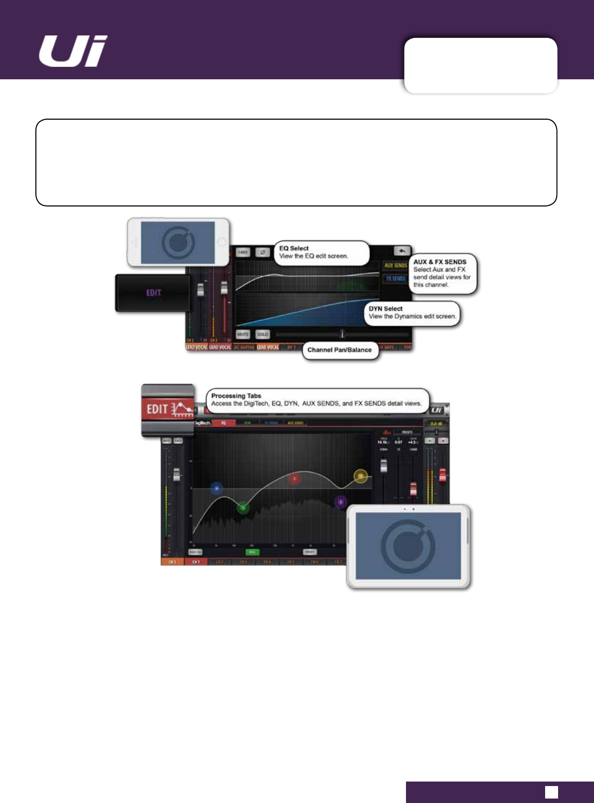
Ui24R User Manual 5.0: CHANNEL EDIT
CHANNEL EDIT
5.0: CHANNEL EDIT
The EDIT page is the basic access point for channel-based signal processing: EQ, dynamics, and FX
and auxiliary sends. The actual processing and options available depend on the channel type.
The selected channel strip will be shown on the left of the EDIT screen. In the phone software, the
default EDIT page is a via-point for more detailed views and also offers access to basic channel
parameters such as pan/balance, phase, phantom power, and more.
EDIT PAGE ACCESS
The EDIT page is available from a number of different Ui Software screens. To select the EDIT page directly
eitherclick/taptheEDITbuttoninthetop-linenavigationbar(tabletsoftware)orselecttheEDITmenuitem
(phonesoftware).
Alternatively you can:
•Doubleclick/taponachannelfadercaptonavigatetochannelEDITmodeEQtab.
•Doubleclick/taponchannellabel(channeltypes:INPUT,LINEIN,PLAYER,SUBGROUP,AUX)tonavigateto
selected channel EDIT page DYN tab.
•Doubleclick/taponachannellabel(channeltype:FXRETURN)tonavigatetoselectedchannelEDITpageFX
tab(GlobalFXparameters).
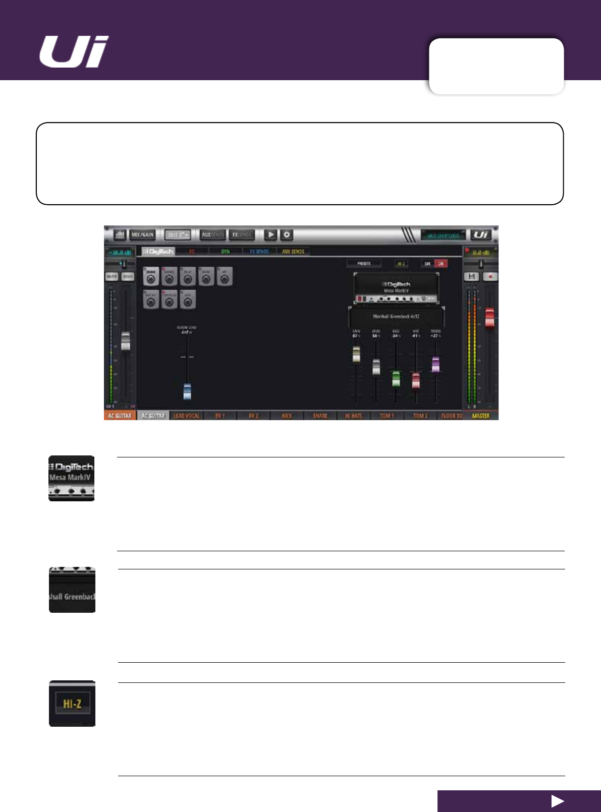
Ui24R User Manual 5.1: DIGITECH
CHANNEL EDIT > DIGITECH
5.1: DIGITECH
DigiTechinputprocessingandchannelviewisavailabletothersttwoUimixerchannels,and
includesHi-Z(highinputimpedance)selectionforsourcessuchdirect-inputguitarpick-ups.
TheDigiTechprocessingincludesampmodelling:Emulationsofguitaramps(withassociatedparam-
eters)andcabinets.TheDigiTechviewalsoallowssingle-vieweditingofselectedchannelfeaturesvia
the‘Jack-PlugButtons’.Note:ThisisanAMPsimulator,it’snotacompleteFXchain.
AMP SELECT
Choose a guitar amp model
Clicking or tapping anywhere on the guitar amp graphic will bring up a pop-up menu of available guitar amp
models.
CAB SELECT
Choose a guitar speaker cabinet model
Clicking or tapping anywhere on the guitar cab graphic will bring up a pop-up menu of available guitar cab
models.
HI-Z ON/OFF
Turn the Hi-Z input on or off
If you have an input source that requires a high impedance input - such as the direct output from electric
guitar pick-ups - turn the Hi-Z option on.
Ui24R User Manual 5.1: DIGITECH
CHANNEL EDIT > DIGITECH
5.1: DIGITECH
DIGITECH ON/OFF
Turn DigiTech processing on or off
When DigiTech processing is turned off, the channel will revert to its standard input stage.
PRESETS
Open the PRESETS management pop-up
You can save and load settings presets for the DigiTech processing using this pop-up.
AMP CONTROLS
Adjust detailed settings for the selected amp model
The controls include GAIN, LEVEL, BASS, MID, and TREBLE. Use the GAIN control to overdrive the amp
model.
CHANNEL CONTROLS
Single view editing of selected input channel controls
Available input channel sections are: FX, High Pass Filter, Notch Filter, Compressor, Gate
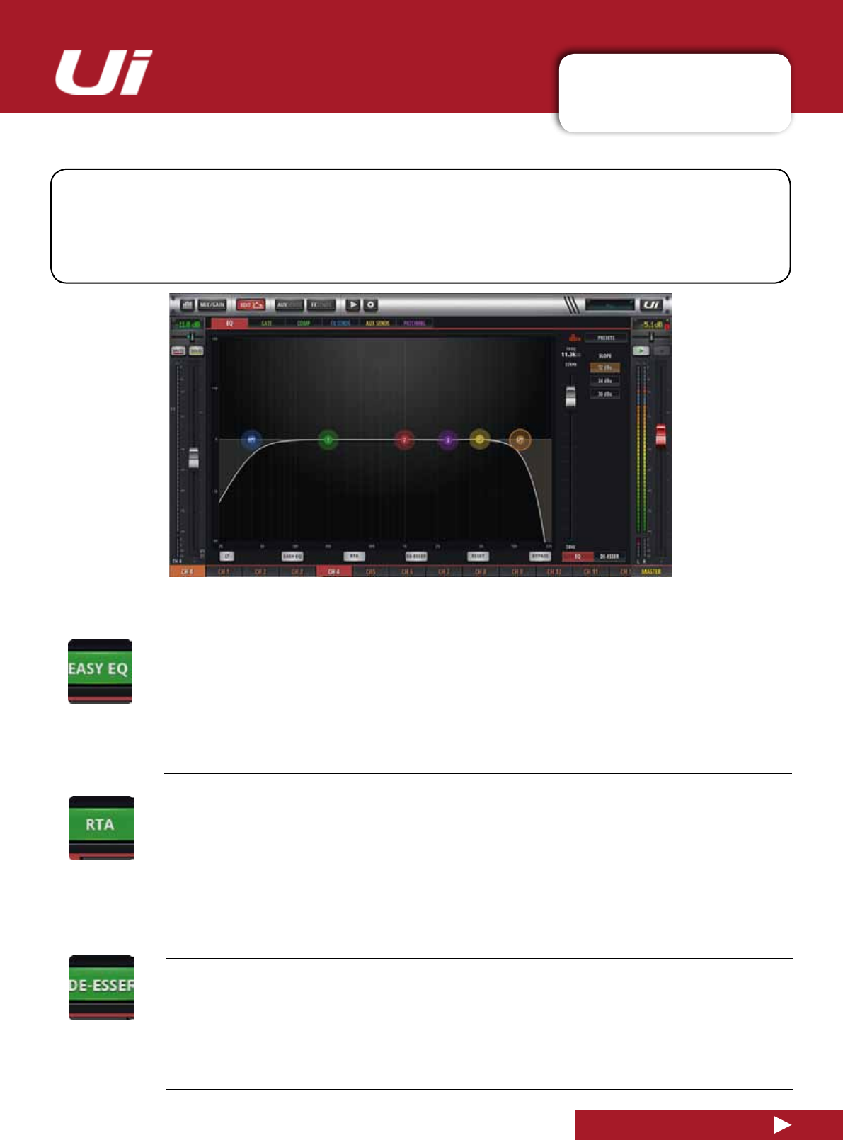
Ui24R User Manual 5.2: PARAMETRIC EQ
CHANNEL EDIT > PARAMETRIC EQ
5.2: PARAMETRIC EQ
EQ adjusts the amplitude of an audio signal at particular frequencies. Ui input channels, FX Return
channels, and Sub Group master channels have a four-band parametric EQ, plus High Pass Filter
(HPF),andaDe-Essercontrolledfromthesamescreen.Thedisplayalsoincorporatesanoptional
RealTimeAnalyser(RTA),whichshowsaspectralviewoftheincomingsignal.Inaddition,theEQcan
beswitchedtoathree-band(xedfrequency,xedQ)‘EasyEQ’.
EASY EQ ON/OFF
Turn Easy EQ feature on or off
EasyEQisathree-band,xedfrequency,xedQmodewithaMidbell-typebandpluslowandhighshelving
bands.SwitchingEasyEQOFFpreservesthe‘curve’intheparametricEQ,However,turningEasyEQON
resets the current curve because parametric EQ settings cannot be mapped to the Easy EQ format.
RTA - REAL TIME ANALYSER
Turn RTA feature on or off
The RTA display shows a real-time spectral view of incoming audio. This is sometimes useful for targeting
speciccharacteristicswithEQbandsquickly.NotethatRTAisonlyactiveononechannelatatime.Ifacti-
vateditwilldeactivateanyotherchannel’sactiveRTA(onotherclients)
DE-ESSER ON/OFF
Turn De-Esser processing on or off
When off, no draggable De-Esser ball will be shown in the main EQ graphic interface.
Ui24R User Manual 5.2: PARAMETRIC EQ
CHANNEL EDIT > PARAMETRIC EQ
5.2: PARAMETRIC EQ
RESET
Reset the EQ to default values
TheEQisset‘at’,andfrequencyandQvaluesareresettodefaults.
BYPASS
Bypass the EQ section of channel processing
This control bypasses only the parametric EQ. HPF and De-Esser processing is unaffected.
EQ / DE-ESSER FADER CONTROL
Choose EQ or De-Esser fader control
Controls for whichever is selected are assigned to the three control faders. For EQ, the faders show values
for the currently selected band.
DS - DE-ESSER BALL
Draggablegraphic‘ball’forDe-Essercontrol
Dragthisgraphicelementtocontrol.UP/DOWNadjustsThreshold,LEFT/RIGHTadjustsfrequency;usea
pinch-gesture or mouse-wheel/track-pad scroll on DE-ESSER ball to adjust the ratio value. Double-click/tap
to reset.
1/2/3/4 - EQ BAND BALL
Draggablegraphic‘ball’forEQbandcontrol
Dragthisgraphicelementtocontrol.UP/DOWNadjustsGain,LEFT/RIGHTadjustsfrequency;useapinch-
gestureormouse-wheel/track-padscrollontheEQballtoadjust‘Q’value.Double-click/taptoresetan
individual band.
Ui24R User Manual 5.2: PARAMETRIC EQ
CHANNEL EDIT > PARAMETRIC EQ
5.2: PARAMETRIC EQ
HPF/LPF BALL
Draggablegraphic‘ball’forHighPassandLowPassFiltercontrols
Drag this graphic element to control. Left/Right adjusts Cut-Off frequency. Double-click/tap to reset. Right
Hand side of the screen displays selectable slope.
DE-ESSER THRESHOLD
Fader control of De-Esser Threshold
De-EsserthresholdisthelevelatwhichtheDe-Esserstartstoattenuatethe‘ess’band.ToaccesstheDe-
Esser fader controls in phone software, tap the DE-ESSER SETUP button.
DE-ESSER RATIO
Fader control of De-Esser Ratio
De-EsserRatioistheamountbywhichthe‘ess’bandisattenuatedwhentheaudiolevelcrossesthe
Threshold. To access the De-Esser fader controls in phone software, tap the DE-ESSER SETUP button.
DE-ESSER FREQUENCY
Fader control of De-Esser Frequency
DeterminesthecentrefrequencyoftheDe-Esserdynamiclter-thefrequencyonwhichthede-essing
process is focussed. To access the De-Esser fader controls in phone software, tap the DE-ESSER SETUP
button.
HPF/LPF SLOPE CONTROL
HighpassandlowpasslteringisavailabletoUi24RusersandisaccessiblethroughtheParametricEQ.
High Pass means only allowing the higher frequencies to play through, Low Pass means only allowing lower
frequenciestoplaythrough.ByusingthesetwoltersontheParametricEQtheusercantailorthesoundto
suittheirspecicPAsetup.TheSlopecontrolaltersthedegreeofltering.
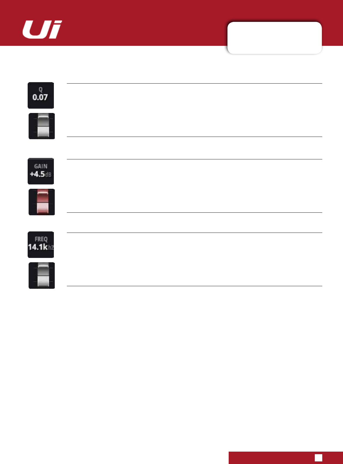
Ui24R User Manual 5.2: PARAMETRIC EQ
CHANNEL EDIT > PARAMETRIC EQ
5.2: PARAMETRIC EQ
EQ Q
FadercontrolofEQ‘Q’
Q is effectively a measure of how tall and thin the bell shape of the EQ band is - the lower the Q, the wider
the bandwidth affected, and vice versa. Fader control of EQ is only available with tablet software. Double-
click/tap to reset.
EQ GAIN
Fader control of EQ Gain
The amount by which the selected EQ band is either boosted or attenuated. Fader control of EQ is only
available with tablet software. Double-click/tap to reset.
EQ FREQUENCY
Fader control of EQ band Frequency
Fader control of EQ is only available with tablet software. Double-click/tap to reset.
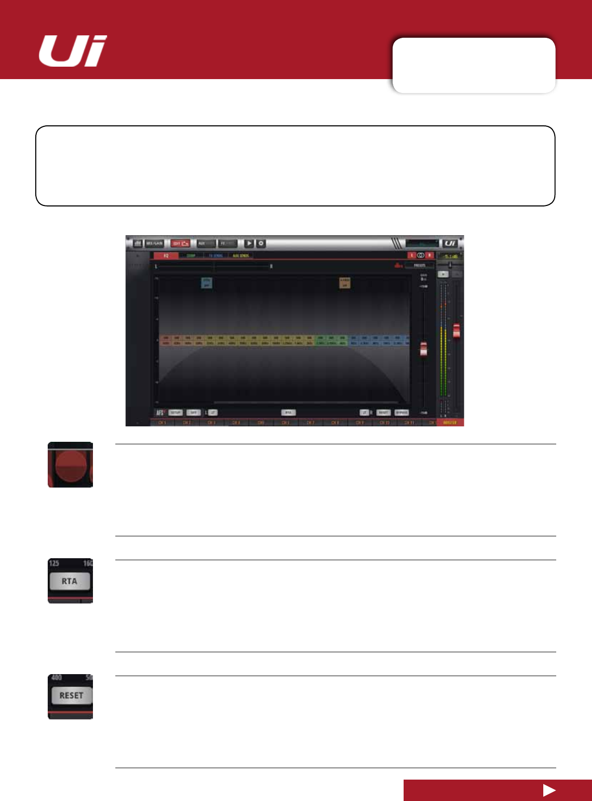
Ui24R User Manual 5.3: GRAPHIC EQ
CHANNEL EDIT > GRAPHIC EQ
5.3: GRAPHIC EQ
UiAuxSendMasterchannelsandtheStereoMasterChannelincorporateGraphicEQ(GEQ)instead
oftheparametricEQoftheinputchannels.Thisincludes31xedfrequencybands(whichcanbe
scrolledacrossthescreen)withadjustableboost/cut.Inaddition,theGEQscreengivesaccesstothe
dbx AFS2(AutomaticFeedbackSuppression)processing.Thedisplayalsoincorporatesanoptional
RealTimeAnalyser(RTA),whichshowsaspectralviewoftheincomingsignal.
HPF/LPF
Master Outputs and Aux/Matrix Out 1/2
HPFandLPFcanbedraggedtosetupcrossoverpointsandlters
RTA
Activate the Real Time Analyser feature
The RTA display shows a real-time spectral view of incoming audio. This is sometimes useful for targeting
speciccharacteristicswithEQbandsquickly.
RESET
ResettheGEQto‘at’
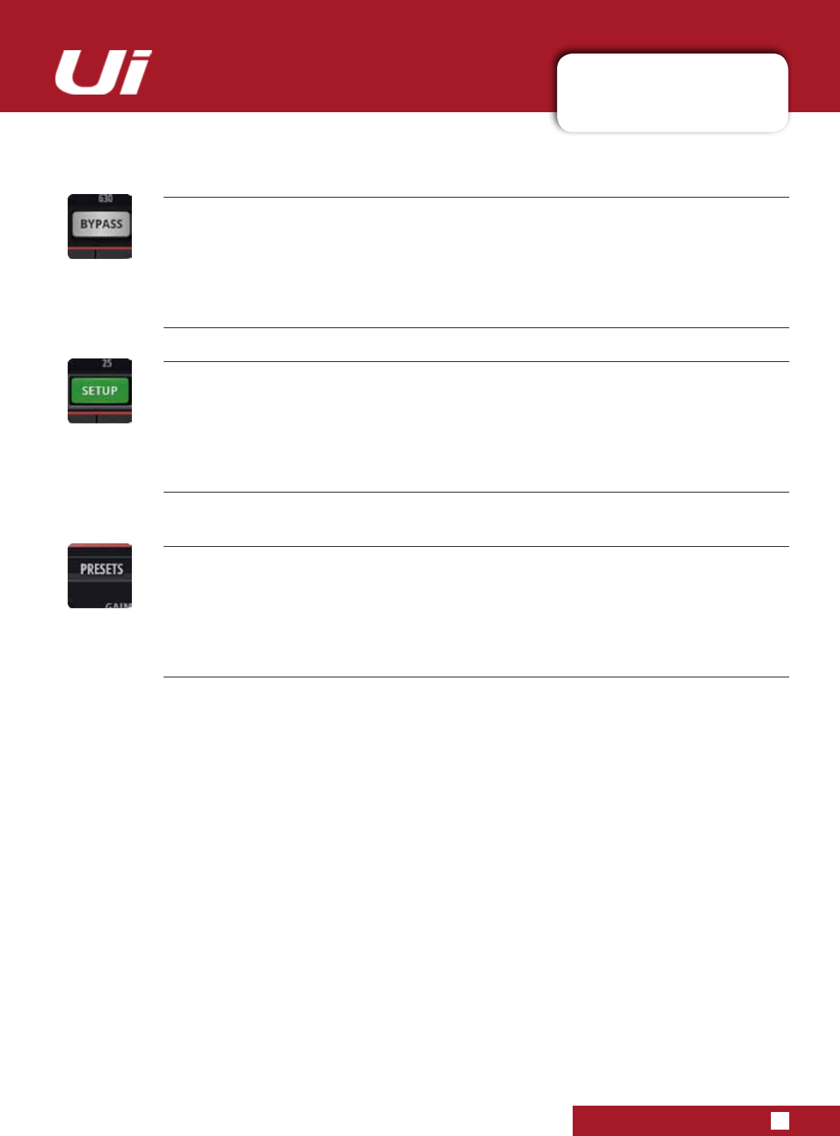
Ui24R User Manual 5.3: GRAPHIC EQ
CHANNEL EDIT > GRAPHIC EQ
5.3: GRAPHIC EQ
BYPASS
Bypass the GEQ processing
dbx AFS2 SETUP
Set up and operate the feedback elimination system for this bus.
Only available with tablet software. See section 5.3.1 for more detail.
PRESETS
Save / load GEQ presets
Brings up a standard preset management pop-up box.
SCROLLING SCREEN
InthosescenarioswheretheusersinterfaceisunabletotthefullGraphicEQ.Itcanbeaccessedby
scrolling along the parameters to make use of the full range of frequencies.
HPF and LPF
The Graphic EQ of AUX/Matric 1 and 2 and Master out can be used to set up crossover frequencies for the
Aux/Master channels.
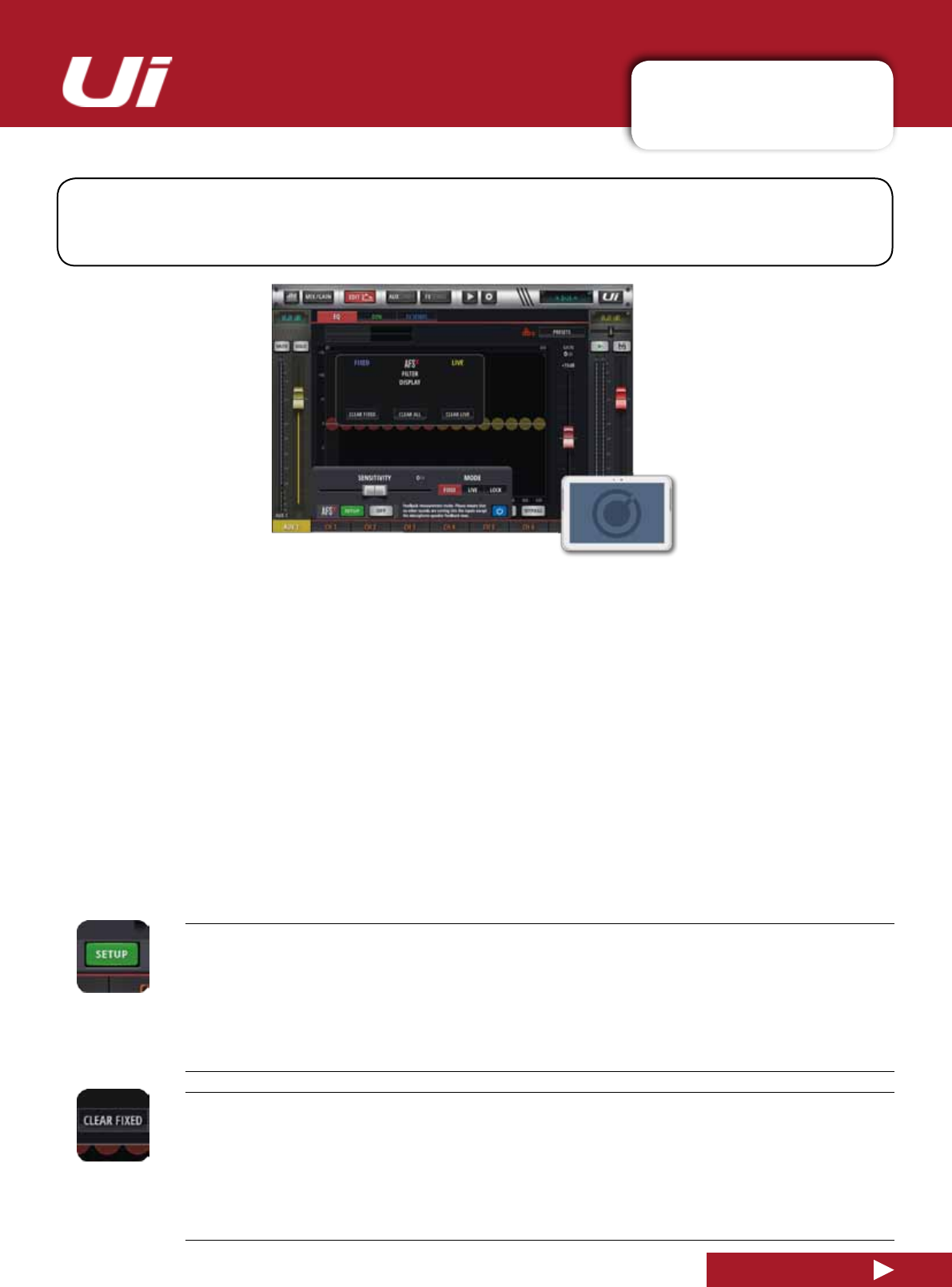
Ui24R User Manual 5.3.1: AFS2
CHANNEL EDIT > GRAPHIC EQ > AFS2
5.3.1: AFS2
AFS2isadbxfeedbacksuppressionsystemthatuses12intelligentlterstodetectandeliminate
feedback across the audio spectrum. You can set AFS2 up on the master stereo output and/or Aux bus
masterchannelsbynavigatingtothechannel’sEditscreenandselectingtheEQtab.
AFS2 works in two modes. Fixed modeisusedfor‘ringingout’asystembefore a performance to ensure
maximum headroom. Live Mode,continuouslyupdateslterplacementandisusedduring a performance.
LiveltersaresmarterthanFixedlters.Theyhavetheabilitytodetectfeedbackwithincomplexprogram
material. This makes them ideal for protecting the system from feedback as conditions change during the
performance.Livelterscanalsodetectwhentheyarenolongerneededandremovethemselvesfromthe
chain,effectivelyrestoringsonicdelityandfreeingupLiveltersforuseelsewhere.
In normal operation, you would setup AFS2 in Fixed mode before a performance, then switch to Live mode
for the actual performance.
Ringing Out The Sound System
Fixedltersaresetbeforeaperformanceinaprocesscalled‘ringingoutasystem’.Thisisdoneafterall
other system EQ has been performed. Ringing out the sound system for feedback before use allows you to
squeezemoregainoutofthesystembeforetheonsetoffeedbackandcanhelpensureyou’renotrightat
the edge of feedback during system use.
dbx AFS2 SETUP
Set up and operate the feedback elimination system for this bus.
A dialogue box will open up with setup options.
CLEAR FILTERS
Clear the AFS2ltersforanewperformance/set-up
Allltersneedtobeclearedbeforenormalset-up.However,youcanalsoresettheLiveandFixedlters
independently, depending on need.
Ui24R User Manual 5.3.1: AFS2
CHANNEL EDIT > GRAPHIC EQ > AFS2
5.3.1: AFS2
AFS2 MODE
Choose LIVE, FIXED, or LOCK
Fixed mode is for pre-performance set-up, Live mode is for use during performance, and LOCK prevents
changestothecurrentltersstatus.
SENSITIVITY
Adjust the input level feeding the AFS2 detector and make AFS2 more or less prone to mark a
signal as feedback.
Setting this parameter high will allow AFS2 to detect the feedback and notch it out more quickly. Conversely,
setting it low will cause AFS2tobealittlemorehesitanttosetalteronthefeedbackuntilitreachesa
higher level.
ON/OFF
Turn ON the AFS2 process.
You must make sure AFS is switch ON to use the process.
Manual AFS2 Set-up in FIXED mode (Ringing Out The System)
1)MakesureallltersareclearedandsettheAFS2 process to Bypass using the blue bypass button.
2)Performasoundcheckandsetuparoughmixforallmicrophonesthatwillbeactiveduringthe
performance. Take note of the output fader position for the aux master or stereo master that you are ringing out – your
TARGETGAINwillbearound5dBabovethis(seestep6).
3)Ifnoisegatesarebeingusedonactivemics–includinginsideFXprocessors,bypassthembefore
ringing out the system. You can re-enable them once the ring-out procedure is complete.
4)Havethemusiciansstopplayingandfullylowerthemasterbusfaders.NOTE:Whenringingoutthesystemin
Fixed Mode, any sustained sound detected by AFS2willtriggerFixedlterstobeset.Therefore,makesurethemicro-
phones are active, but there is no appreciable signal present at the mics.
5)Ensurethemusiciansarenotplaying,thensettheFILTERMODEparametertoFIXED.
6)Un-bypasstheAFS2 process then slowly raise the master fader until you reach your target gain
(describedinstep2)orrunoutofFixedModelters,whicheverhappensrst.
7)LowertheMasterbusfaderbacktoperformancelevel.
8)SettheFILTERMODEparametertoLIVE.ThesystemisnowreadyforuseandanyavailableLivelterswillbe
availableforon-the-yfeedbacksuppressionduringtheperformance.
AFS2 has a dedicated preset manager whereby users LOAD/SAVE/RENAME/DELETE AFS2 presets to connected
USB media.
To load/save/rename/delete AFS2 PRESETS:
- Go to any AUX or the MASTER EQ edit page
- Click/tap the AFS2 SETUP button
-Click/taponthePRESETSbuttonfoundinthemiddleoftheAFS2lterdisplaymodal
- Use the PRESETS manager to LOAD/SAVE/RENAME/DELETE AFS2 presets to connected USB media
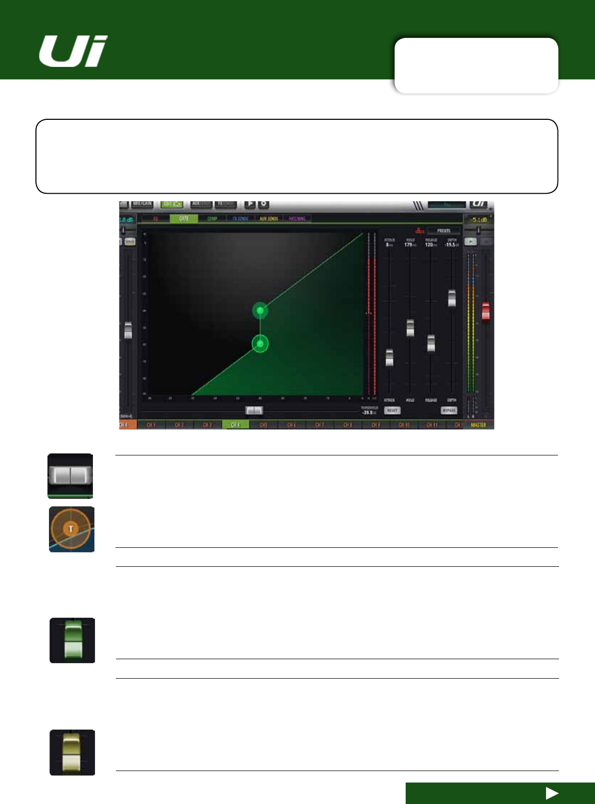
Ui24R User Manual 5.4.1: GATE
CHANNEL EDIT > GATE
5.4.1: GATE
The Ui24R Gate section is accesible via the Edit Tab on the top toolbar. A Gate is a threshold-driven
gain reduction process normally used to attenuate a signal when its level falls below the Threshold.
SettingtheThresholdjustaboveanoiseoororbackgroundnoise,forexample,willallowtheGateto
attenuatethesourceduringperiodswhenthemaininput(voice,instrumentetc)issilent.
THRESHOLD
Adjust the Threshold of the gate
ThetabletversionofthesoftwareincludesahorizontalTHRESHOLDfader.Youcandragtheorange‘T’ball
in the dynamics graphic in both phone and tablet versions.
ATTACK
Adjust the Attack of the gate
The attack time controls the speed of the gate opening. The time is in microseconds, under one second.
A gate that opens too quickly on a slower signal attack can produce a click sound. The simple solution is
to extend the attack time until the click sound disappears. Consider very fast attack times for percussive
instrumentsandslowertimes(10msormore)foreverythingelse.
HOLD
Adjust the Hold time.
The hold time is the minimum time the gate is held open. Hold time is often set to a minimum of 20-30
milliseconds to prevent chatter. Chatter is the constant opening and closing of a gate due to a high-speed
uctuatingsignallevel.
Gate Screen Grab
Ui24R User Manual 5.4.1: GATE
CHANNEL EDIT > DYNAMICS
5.4.1: GATE
DEPTH
Adjust the gate Depth
RELEASE
Adjust the Gate Release
Thisisthespeedatwhichthegatereturnsto‘noattenuation’afterthesignallevelhasfallenbelowthe
threshold level.
GRM - METERING
Gain reduction metering
There are three meters: Input signal, output signal, and a meter showing the amount of attenuation currently
being applied due to the dynamics processing.
RESET
Reset the Dynamics for this channel to default values
BYPASS
Bypass the Dynamics for this channel
SOFT KNEE / HARD KNEE
Set SOFT KNEE or HARD KNEE mode for the compressor
This determines how threshold level is interpreted. HARD KNEE mode means that the threshold represents
an abrupt transition. SOFT KNEE means that it represents a gradual transition.

Ui24R User Manual 5.4.1: GATE
CHANNEL EDIT > DYNAMICS
5.4.1: GATE
PRESETS
Save / load Dynamics presets
Brings up a standard preset management pop-up box.
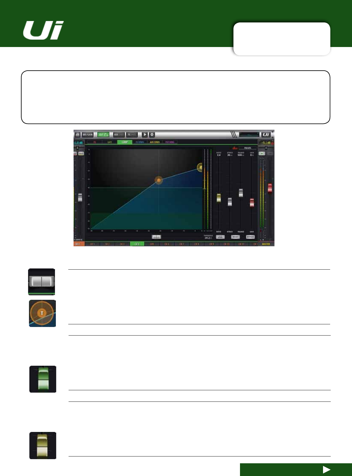
Ui24R User Manual 5.4.2: COMPRESSOR
CHANNEL EDIT > COMPRESSOR
5.4.2: COMPRESSOR
The Ui24R Compressor section is accesible via the Edit Tab on the top toolbar. A compressor is a
threshold driven process used to reduce the dynamic range of a signal by applying gain reduction
whenthesignallevelexceedsthethresholdandapplying‘make-upgain’tokeeptheoveralllevelcon-
sistent. You can use compression to increase the apparent loudness of a signal without increasing the
peak level, or to control overly dynamic sources.
THRESHOLD
Adjust the Threshold of the compressor
ThetabletversionofthesoftwareincludesahorizontalTHRESHOLDfader.Youcandragtheorange‘T’
ball in the dynamics graphic in both phone and tablet versions. This refers to how loud the signal is before
compression is applied.
ATTACK
Adjust the Attack of the compressor
The attack time controls how quick it takes for the compressor to work. The time is in microseconds, under
one second.
RATIO
Adjust the compression Ratio
How much compression is applied. For example, if the compression ratio is set for 6:1, the input signal will
have to cross the threshold by 6 dB for the output level to increase by 1dB.
Compressor Screen Grab
Ui24R User Manual 5.4.2: COMPRESSOR
CHANNEL EDIT > COMPRESSOR
5.4.2: COMPRESSOR
RELEASE
Adjust the Release of the compressor
How soon after the signal dips below the threshold the compressor stops.
GAIN
Adjust the Gain of the compressor
Allowsyoutoboostthecompressedsignal.ascompressionoftenattenuatesthesignalsignicantly
HOLD
Adjust the Hold time.
The hold time is the minimum time the gate is held open. Hold time is often set to a minimum of 20-30
milliseconds to prevent chatter. Chatter is the constant opening and closing of a gate due to a high-speed
uctuatingsignallevel.
PRESETS
Save / load Dynamics presets
Brings up a standard preset management pop-up box.
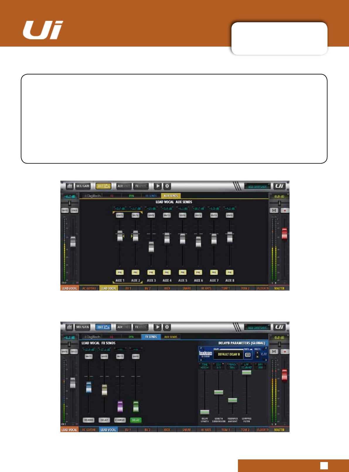
Ui24R User Manual 5.5: AUX/FX SENDS
CHANNEL EDIT > AUX/FX SENDS
5.5: AUX/FX SENDS
The AUX and FX SENDS tabs in the EDIT screen are a convenient way to access all output
contributionsforasinglechannel-asopposedtothe‘mixview’approachofthededicatedAUXSEND
and FX SEND pages. The AUX SENDS view/tab for both phone and tablet software versions includes
PRE/POST and MUTE buttons for each send.
The FX SENDS view/tab for both phone and tablet software versions offer MUTE buttons and
selections for editing the settings of the different FX processors. In the phone software, clicking/
touching one of these takes you to an additional detail view to edit that FX processor.
For details on the internal FX processors, please see section 7.
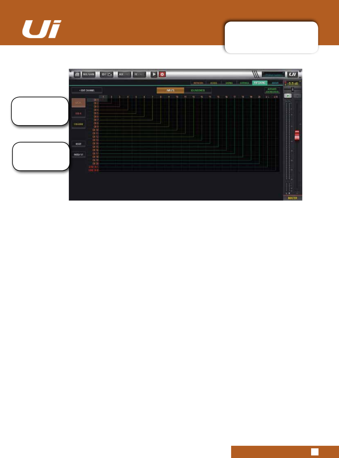
Ui24R User Manual 5.6 PATCHING
5.6 PATCHING
LOCAL
The Patching screen enables the user to select either the input source 1-20 or L/R Line In for each channel.
By selecting CHANNEL/EDIT/PATCHING the user will be able to nominate the selected source for each
channel
OVERVIEW
The Overview Tab will give the user, at a glance, a full overview of the patches and connections that have
been set up. These can be edited on the overview screen with all changes being global
USB-A
2TrackorStereoUSBlescanbepatchedtoavailableslots1-22usingCHANNEL/EDIT/USB-A
USB-DAW
MultitrackUSBlescanbepatchedfromyourDAWtoavailableSlots1-32usingCHANNEL/EDIT/USB-
DAW
RESET
Reset will quickly reset the patch screen to its default setting..
PATCH 1:1
Patch 1:1 makes easy work of patching by creating a 1:1 connection of physical inputs to mixer channels
for all channels.
Patches can be set
up for Local inputs,
Multitrack USB A and
Multi-track USB-DAW
Quick reset and Patch
1:1 make setting and
resetting patches a
one touch solution.
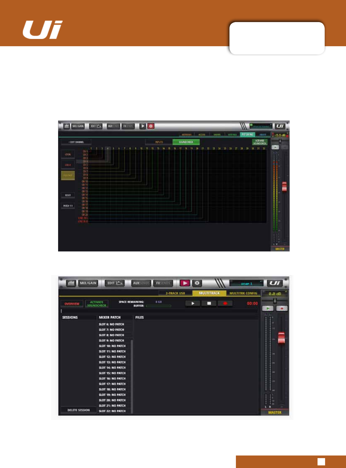
Ui24R User Manual 5.6 PATCHING
5.6 PATCHING
SOUNDCHECK
Soundtcheckisbasicallyanothersetofpatches.Itcanbeusedtosetupatrialmixviapre-recordedles
on USB for example or work on a straight live soundcheck or a mixture of both. Setup is the same as it is
for normal patching applications. Once the Soundcheck mode is engaged the selection panel will be green.
There are two ways to activate Soundcheck either through the SETTINGS>PATCHING>OVERVIEW
PAGE or the PLAYER>MULTITRACK PAGE
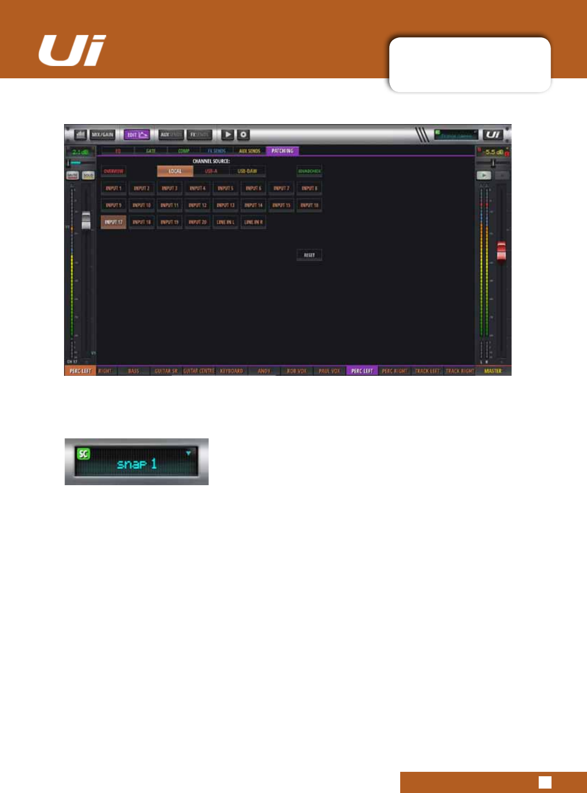
Ui24R User Manual 5.6: PATCHING
5.6 PATCHING
SOUNDCHECK ASSIGN PAGE
The Soundcheck Assign page assigns the soundcheck patch for the selected channel.
SOUNDCHECK INDICATOR
The Soundcheck Indicator is located in the top left corner of the Level 1 LCD Panel. This will
appear to indicate when the Ui is in Soundcheck Mode.
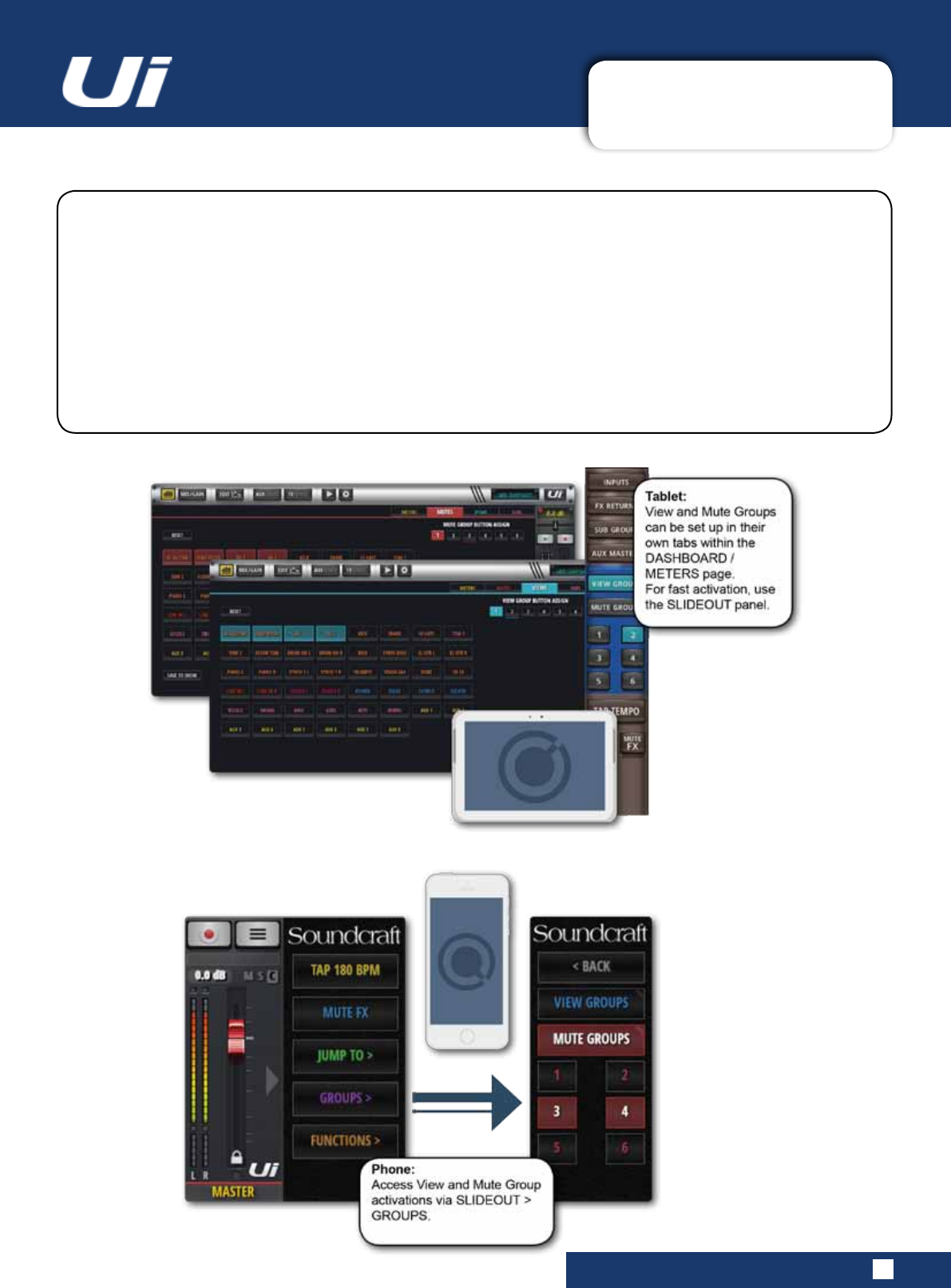
Ui24R User Manual 6.1: VIEW & MUTE GROUPS
MIX FEATURES > VIEW & MUTE GROUPS
6.1: VIEW & MUTE GROUPS
In Ui software you can mute channels individually, or in Mute Groups. There are six Mute Groups
available to be assigned to any muteable channels. To mute all channels in a Mute Group, simply
selecttherequiredMuteGroupbutton.ViewGroupsworkinmuchthesameway,thoughthesedene
mixer channel views. For example, you could assign all vocal channels, plus an aux master to View
Group1forinstantrecall.The‘INPUTS’,FXRETURNS,SUBGROUPS,andAUXMASTERSbuttons
available in the Slideout panel are simply convenient preset View Groups.
ToassignMuteGroups,ViewGroups,(andSubGroups)navigatetotheassignmentpage.InTablet
software, choose the appropriate tab on the Meters page or long-click/touch the respective group but-
ton in the Slideout panel. You can then choose groups and assign channels to them as required.
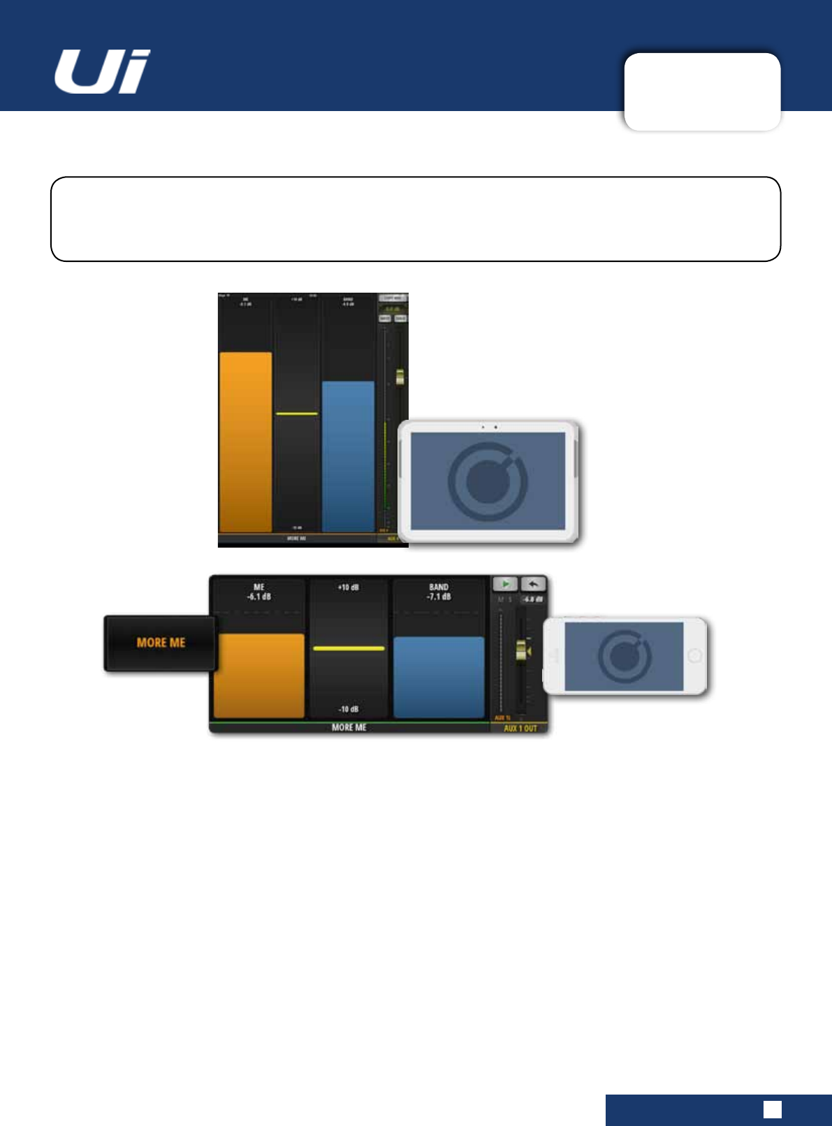
Ui24R User Manual 6.2: MOREME
MIX FEATURES > MOREME
6.2: MOREME
MOREMEallowsuserstoassigntheirownchannels(whichmayincludeavocalmicandan
instrumentchannelforexample)andmixthebalanceofthosechannelswithasinglelargefader.
This is a simple way to mix your own sound against other band members.
To view MOREME in the phone software, open the NAV menu and press MOREME, or it can be accessed
from the AUX SENDS screen with a double press on the green AUX MASTER fader. Double press the
blank section in between the MOREME faders to return to the AUX SENDS screen. In the Tablet software,
choose MOREME from the Slideout panel.
MOREME can be displayed in both landscape and portrait orientations. Landscape is accessed from the
NAV menu, whereas anytime you turn your phone to portrait orientation, the MOREME page is shown in
portrait view.
ForMOREMEtowork,yourstneedtoassignyourMEchannels.Dothisfromachannelsub-menuinthe
MIX page. Long-press a channel name for the channel sub-menu, then select ASSIGN ME.
Next you need to assign your aux output. Still in the MIX screen, scroll along to the AUX MASTER faders,
Long press on your AUX Master output channel and select ASSIGN ME OUT.
When a channel is assigned to MOREME, its channel name is displayed in orange colour.

Ui24R User Manual 6.2: MOREME
MIX FEATURES > MOREME
6.2: MOREME
“MOREME” Portrait Mode ON/OFF
ItisnowpossibletodenewhetherMOREMEisdisplayedautomaticallyinportraitmodeondevices
offeringorientationsupport.Someusersprefertooperatefaderviewpages(MIX,AUX,FX)inpor-
traitdisplayorientationsothefadersare“longthrow”.
MOREME Modes:
MOREME ON - Portrait mode orientation will automatically display the MOREME page
MOREME OFF - Portrait mode orientation will display the regular GUI with extended faders. Some
featuresoftheGUIdisplaywillbe“grayedout”andrestrictedfromviewduetothedimensionlimita-
tions.
Changing the MOREME Mode:
- Go to the SETTINGS-->SETTINGS tab page
- Set the MOREME PORTRAIT MODE option to ON/OFF
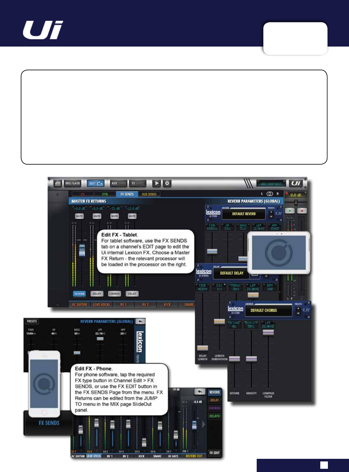
Ui24R User Manual 7.0: FX EDIT
FX EDIT
7.0: FX EDIT
Digital FX are used in all types of audio to help create depth and colour to a mix. The Ui24R has three
internal Lexicon FX processors: Reverb, Delay, and Chorus. The Ui24R has an additional processor
that can either be an additional reverb or delay.
There are dedicated FX Sends and Returns for the internal FX - simply adjust the corresponding FX
Send level and bring up the level of the FX Return channel to incorporate FX into your mix.
See section 4.4 for more details of FX Sends.
FX Edit panels have Preset Save / Recall, and Fader-based parameter adjustment with numeric LCD-
style numeric display.
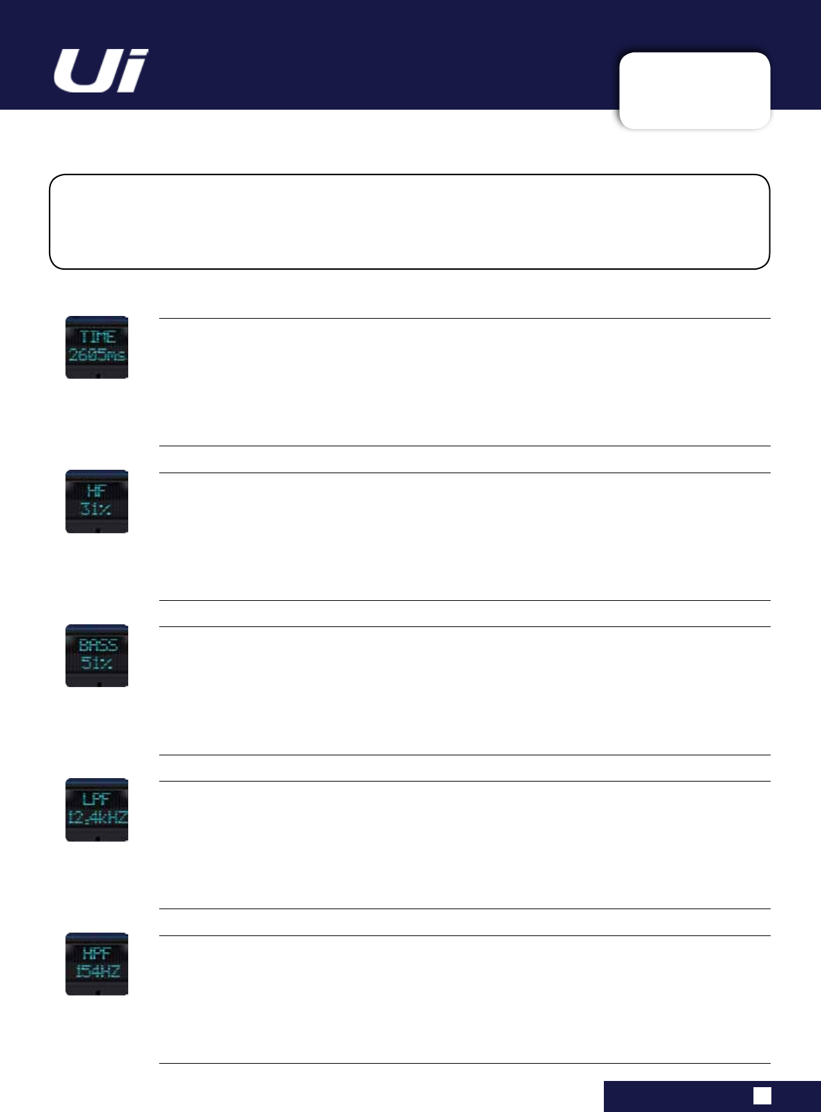
Ui24R User Manual 7.1: REVERB
FX EDIT > REVERB
7.1: REVERB
Reverberation(or“reverb”forshort)isthecomplexeffectcreatedbythewayweperceivesoundinanenclosed
space. Reverb is dependent on many features of that space, including the size, shape and the type of materials
that line the walls. Reverb is a natural component of the acoustic experience, and most people feel that
something is missing without it.
HF
HF Damping
Bydampingthehighfrequenciesyoucan‘tunein’amorenaturalreverberation.
TIME
ReverbTime(milliseconds)
The amount of time it takes for the reverberation tail to decay. Reverb time is an aural indication of the type
of space - large effective spaces have longer reverb times than small absorbent ones.
BASS
Bass Gain
Adding bass to a reverberant signal can help thicken audio that is been weakened by the reverberation algo-
rithm, or create greater clarity in low frequencies that is sometimes masked by reverberation.
LPF
Low Pass Filter Frequency
Higherfrequencysettingsincreasehighfrequencyresponse,creatingbrighterreverbs;lowerfrequencyset-
tings create darker reverbs with more bass frequency emphasis.
HPF
High Pass Filter Frequency
Reduce‘rumble’andundesirablemuddinessbycuttingthelowfrequencies.
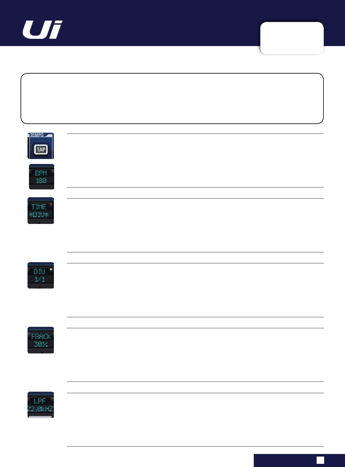
Ui24R User Manual 7.2: DELAY
FX EDIT > DELAY
7.2: DELAY
Delaysrepeatasoundashorttimeafteritrstoccurs.Delaybecomesechowhentheoutputisfedbackinto
theinput(feedback).Thisturnsasinglerepeatintoaseriesofrepeats,eachalittlesofterthanthelast. The Ui
delay time is set in Milliseconds or in musical values. Press the DIV display to access a drop down box with the
availablemusicalnotevalues.PresstheTAPTEMPObuttonrepeatedlytotapinthedesireddelaytime.(Thisis
usuallydoneintimewiththemusic.)PressandholdtheTAPTEMPObuttontomanuallytypeinthedelaytime
in BPM.
TIME
Delay Length
Delay time set in milliseconds.
TAP / BPM
Delay Tempo
Adelaytimesettingthatusesa‘tapped’tempoasaguide.Tapthe‘TAPTEMPO’buttontosetthedelay
time.
The TAP TEMPO button is also available in the control software SlideOut panel.
DIV
Length Subdivision
Delay time set as a musical sub-division of the tempo. Press the DIV display to access a drop down box with
the available musical note values.
FBACK
Controls the number of delay repeats by feeding the delay output signal back into the delay input
This creates a series of delay repeats, each slightly attenuated until they become inaudible. Higher settings
createmorerepeats;lowersettingsreducethenumberofrepeats.Whenthisknobisturnedfullyclockwise,
itengagesRepeatHold–delayrepeatsplaybackinaninniteloop,butnofurtherinputsignalisintroduced
into the delay effect. Repeat Hold is available only on Studio, Mono and Pong Delay.
LPF
LowPassFilter-Frequenciesabovethisareltered/removed
Cutthehighfrequencycontentbyadjustingthecut-offfrequencyofashelvinglter.
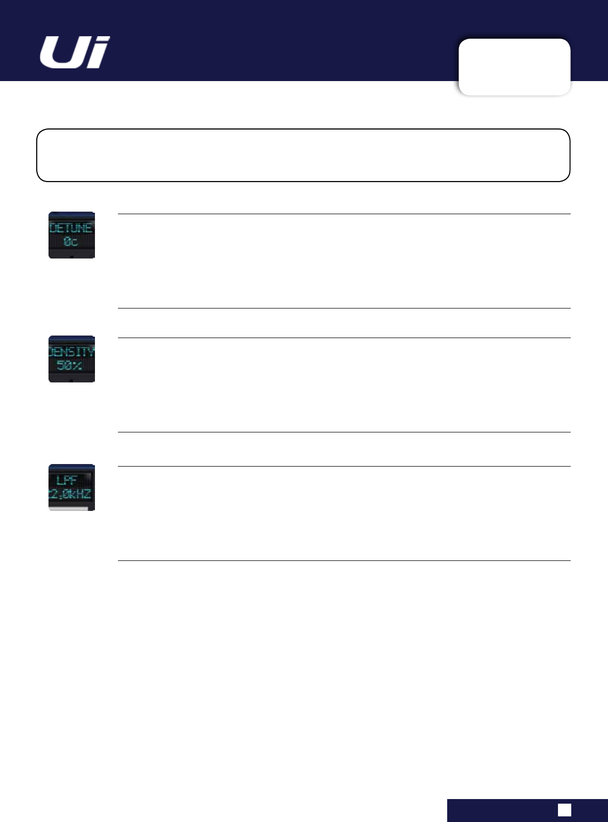
Ui24R User Manual 7.3: CHORUS
FX EDIT > CHORUS
7.3: CHORUS
Chorus creates a lush, full sound by combining two or more signals together where one is unaffected and the
other signals vary in pitch very slightly over time. Chorus is commonly used to fatten up tracks and to add body
to guitars without colouring the original tone. Chorus can also be used with discretion to thicken a vocal track.
DENSITY
Adjust the density of the chorus effect
The more dense the chorus, the thicker and richer the result will be.
DETUNE
Amount of deviation from the pitch of the original signal
LPF
LowPassFilter-Frequenciesabovethisareltered/removed
Cutthehighfrequencycontentbyadjustingthecut-offfrequencyofashelvinglter.
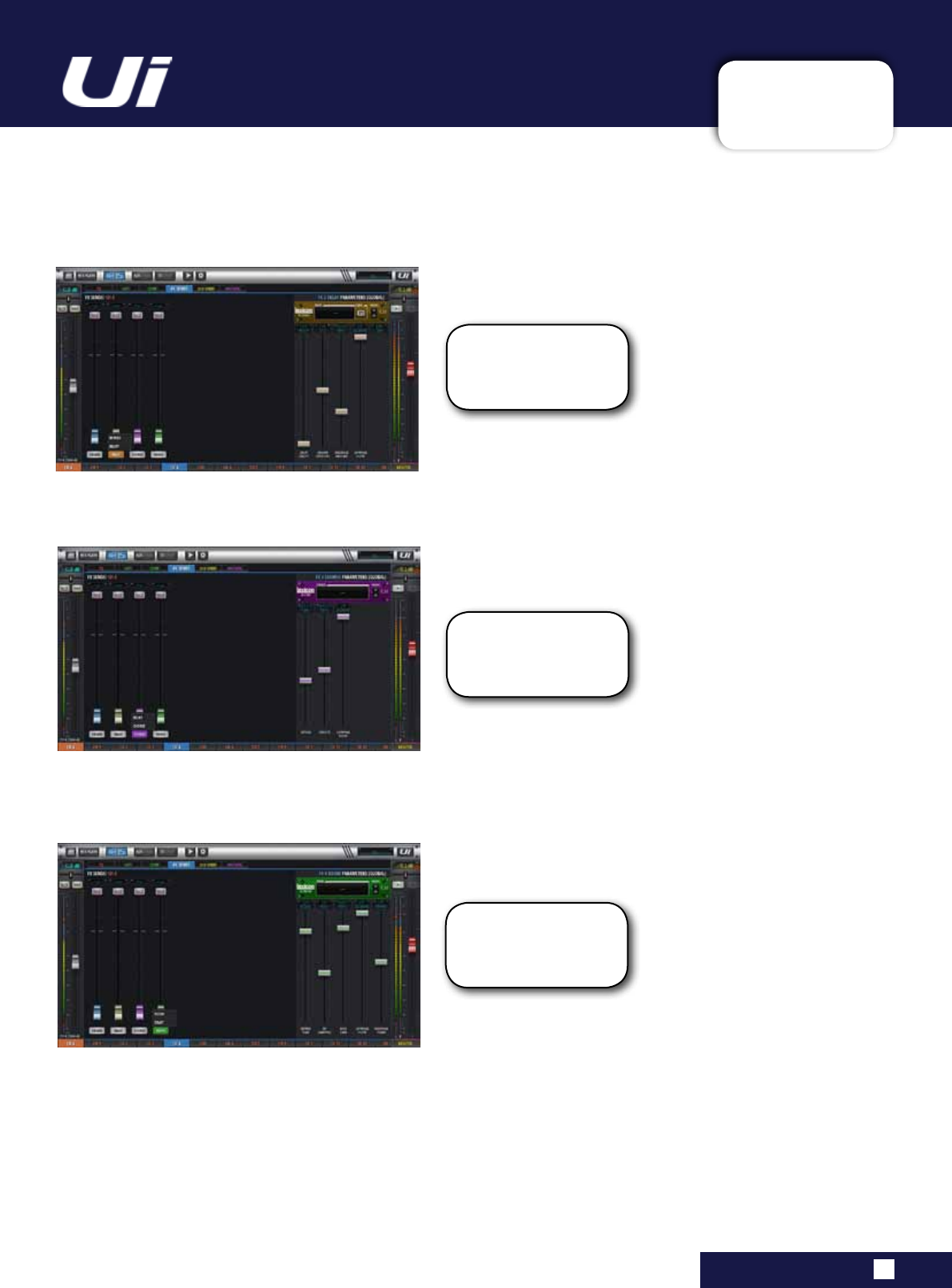
Ui24R User Manual 7.4: FX SCREEN
FX EDIT >
7.4: FX SCREEN
Click and Hold on the ef-
fect name will bring up a
menu for quick selection
of Reverb or Delay
Click and Hold on the ef-
fect name will bring up a
menu for quick selection
of Delay or Chorus
Click and Hold on the ef-
fect name will bring up a
menu for quick selection
of Room or Delay
EFFECTS SCREEN
TheEffectsScreenhasfoureffectspatches.TherstpatchisxedwithahighqualityLexiconreverbbut
the other three are assignable.
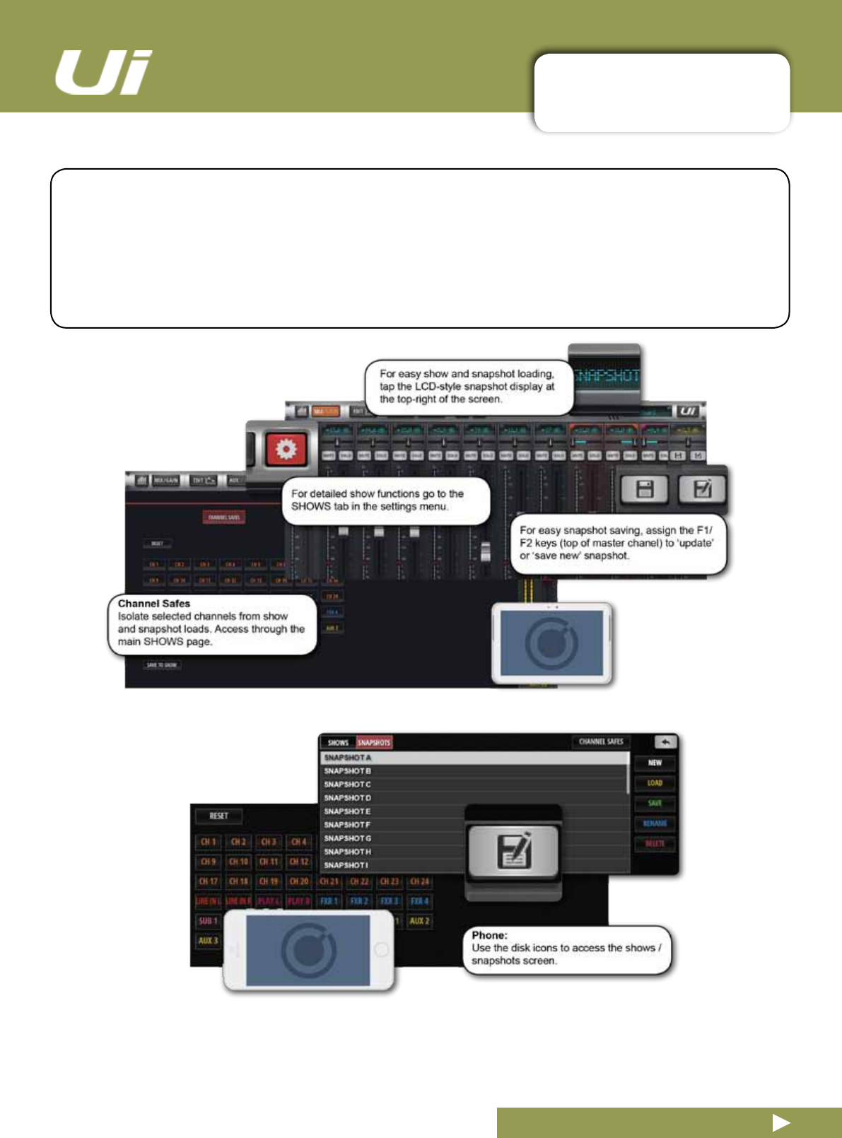
Ui24R User Manual 8.0: SHOWS & SNAPSHOTS
SHOWS & SNAPSHOTS
8.0: SHOWS & SNAPSHOTS
A SHOW is a collection of SNAPSHOTS. A SNAPSHOT is a record of every setting on the console.
You can save and recall snapshots and shows via the Ui control software - Phone or Tablet.
A snapshot remembers every setting of your mixer at one time. A common usage for snapshots is to
have one snapshot per song. So your snapshot list could look exactly like your song list.
At the end of each song, change to the next snapshot and every setting on the mixer is ready for that
song to start.
The SHOWS & SNAPSHOTS page is accessible in the tablet software from the SETTINGS page OR by
tapping/clickingtheLEDdisplayinthetopnavigationbar(whichdisplaysthenameofthecurrentlyloaded
snapshot).Thequickkeytothesnapshotspop-upis[8].YoucanalsoassignanF1orF2key(topof
MasterChannel)toupdatethecurrentsnapshotorcreateanewone.Inthephonesoftware,simplytapthe
disk icon or assign the SlideOut F1 key to a snapshot function.

Ui24R User Manual 8.0: SHOWS & SNAPSHOTS
SHOWS & SNAPSHOTS
8.0: SHOWS & SNAPSHOTS
The unit ships with the Default Show loaded, and the * Init * snapshot. It is a good idea to create a new
Show to work with and use the Default Show is an easy route back to default settings.
Tosetupashow,fromaSHOWS&SNAPSHOTSview(Settings)selectSHOWSandpresstheNEWbut-
ton. Then name your show.
In the SHOWS AND SNAPSHOTS page you can create, load, delete, and rename shows and snapshots.
NowtakeasnapshotbypressingtheSAVEbutton(nexttotheSNAPSHOTScolumnorinthe
SNAPSHOTSview).YoucanalsoassigntheUpdateSnaphotandNewSnapshotfunctionstotheF1and
F2keys(Settingsmenu).
Loaded Shows and Snapshots are shown in red text.
When you take a snapshot, it is saved inside the current Show.
Snapshot delete operations only work on Snapshots in the curent show. If you try to delete a Snapshot
from a Show that is not loaded, an error message will appear.
USB Import / Export
You can export shows to and import Shows from a USB drive inserted into the USB port in the main unit.
To Export, select the Show in the Show List, Touch EXPORT, then select the USB drive and touch OK. To
import, touch IMPORT, select the Show you wish to import, then touch OK.
Channel Safes
Activating a channel safe means the highlighted channel will not change when a new snapshot is recalled.
YoucancongureselectChannelSafes,andsavethemtothecurrentshow,viatheCHANNELSAFES
view(accessedthroughthemainSHOWS&SNAPSHOTSpage).
AFS2 Preset manager
AFS2 settings are no longer saved in a SNAPSHOT /SHOW.
AFS2 now has a dedicated preset manager whereby users LOAD/SAVE/RENAME/DELETE AFS2 presets
to connected USB media.
To load/save/rename/delete AFS2 PRESETS:
- Go to any AUX or the MASTER EQ edit page
- Click/tap the AFS2 SETUP button
-Click/taponthePRESETSbuttonfoundinthemiddleoftheAFS2lterdisplaymodal
- Use the PRESETS manager to LOAD/SAVE/RENAME/DELETE AFS2 presets to connected USB media
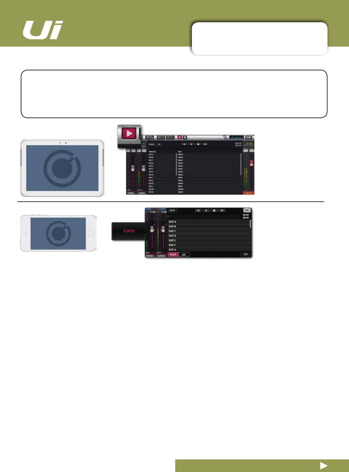
Ui24R User Manual 9.0: MEDIA PLAYER & RECORDER
PLAYBACK & RECORDING
9.0: MEDIA PLAYBACK & RECORDING
The Ui mixer has built-in media factilities. The Ui24R can playback via a USB memory stick, and the
Ui24R can play and record. The player can be used for backing tracks or for background music in
between sets, for example, while the Record facility records the main stereo mix. Playback is via the
PLAYBACK L and PLAYBACK R channels - these are normal input channels dedicated to the USB
playback function.
TheRecord(Ui24R)andPlaybackfeaturesuseoneortwoUSBMemorysticksplacedintheUSBsockets
on the Ui hardware. The Ui24R has both play and record sockets on the front panel, the Ui24R has a USB
‘PLAY’socket.TherearetwomoreUSBsocketsonthesidepaneloftheunit.
Press the MEDIA icon to enter the player page, or go via the PLAYER menu button in Phone software.
Filescanbeplayedfromaplaylistordirectlyfromthelelist.
Menu Pop-up
Press and hold the PLAYER channel name to bring up the channel menu. The menu items are:
Disable Stereo Link
This feature separates the stereo channel into two mono faders. This is useful for musicians who want the
audioononechannelandaclick(tempo)trackontheotherchannel.
Place Before Inputs
This useful feature moves the Player fader before Channel 1, so it is the 1st fader in the mixer.
File Types
AudiolesmustbesavedtotheUSBstickaseitherWAV,AAC,MP3,OGG,AIFF,orFLACles.Oncethis

Ui24R User Manual 9.0: MEDIA PLAYER & RECORDER
PLAYBACK & RECORDING
9.0: MEDIA PLAYBACK & RECORDING
is completed, insert your USB stick into the USB slot labelled PLAY on the top of the Ui hardware and your
songleswillbeshownintheUSBmedialescolumn.
F1 & F2 PLAY
InthetabletsoftwaretheF1&F2buttonsabovetheMasterfader(andinthephonesoftwaretheF1button
intheSlideOutpanel)canbeassignedtoplaynextsong(intheSETTINGS>CONFIG/SETUPscreens).
Iftheplayerissettomanual,thentheplayerwillstopatthenishofeachsong.PressingtheF1/F2play
button will play the next song in the list. This allows the musician to play the next song in his set without
having to view the player page.
Manual / Auto
Manual mode means the player will stop playing at the end of each song.
Automodemeanstheplayerwillautomaticallystartplayingthenextsonginthelelist.
Cue
The Cue button is a jump to next song feature. CUE is only needed when working in manual mode.
ItallowsthenextsongtobeplayedusingtheF1orF2PLAYbutton(abovetheMasterfader),withouthav-
ing to jump to the media player page before every song.
Recorder
Recording of the Master Stereo Output can be activated with a RECORD button. You can assign F1 and/or
F2 buttons to this function or use the large side panel view player mode.
2TK USB
2-Track Stereo USB recording is available on the Ui24R.
Newshufebutton.
MTK USB Record
Along with 2-Track stereo recording, the Ui24R can also multitrack record up to 22 separate tracks which
can then be imported into any DAW software for further processing or mastering.
MTK USB Playback
Individual multitrack recordings can be played back through the GUI and remixed. Perfect for making a trial
mix in a new venue before the musicians roll up or for use as backing tracks.
Note. MTK Playback and Record USB stick needs to be inserted in the front recording slot and
to enable 22 simultaneous tracks to be recorded, the USB write and read speed off the inserted
media must be compliant ( the buffer setting in the mixer interface will indicate buffer size and any
write speed issues.
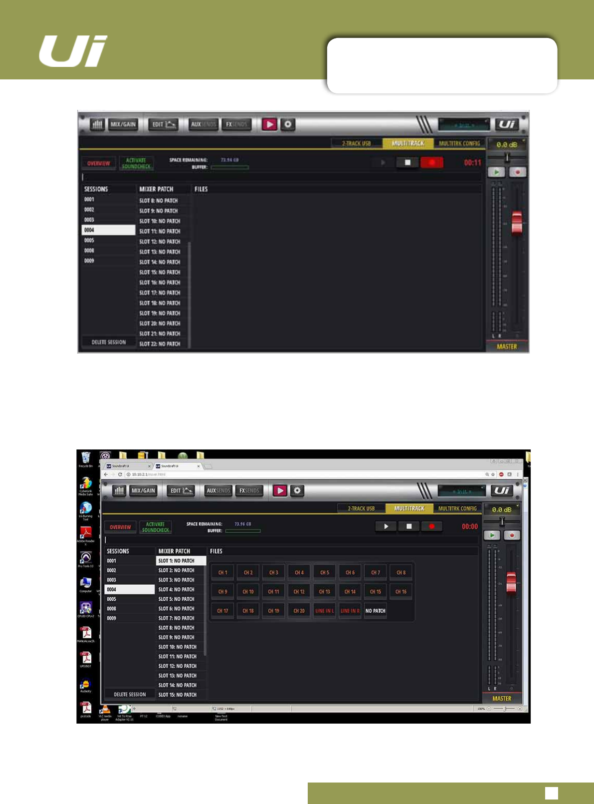
Ui24R User Manual 9.0.1: MTK PLAYER & RECORDER
MTK PLAYBACK & RECORDING
9.0.1: MTK PLAYBACK & RECORDING
MULTI-TRACK PLAYBACK & RECORDING FROM USB
The Ui24R can playback and record multi-track from USB up to 22 tracks. Patches will be set by dou-
ble clicking a mixer patch slot which will open up the mixer patch assignment modal. Any changes will
be universal. Sessions, Mixer Patches and Files are all displayed on this screen.
By clicking on a session number, playback will commence once the play icon is activated and
stopped with the stop button, Recording will commence or stop by activating the record button.
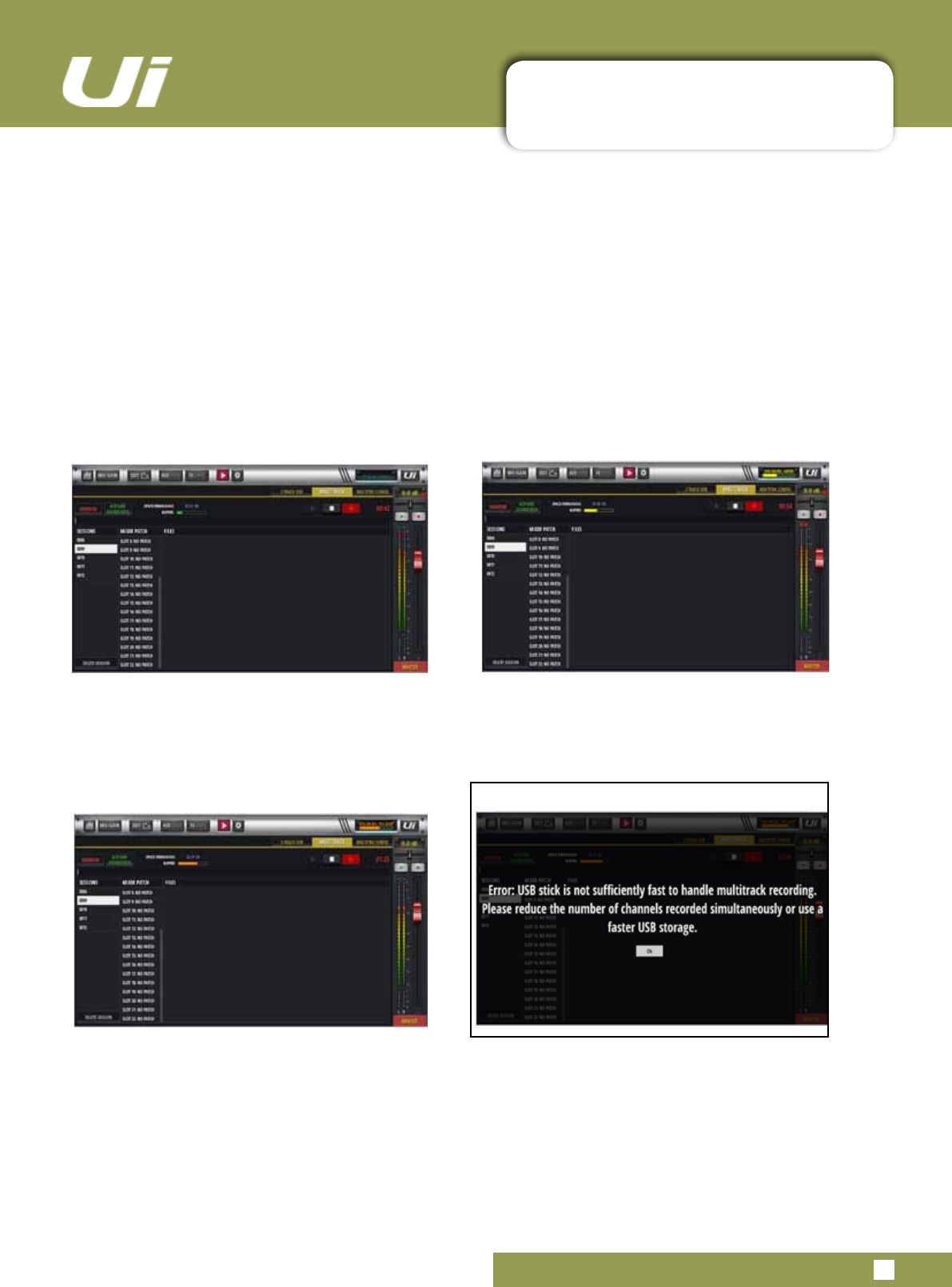
Ui24R User Manual 9.0.2: USB PLAYBACK & RECORDING
PLAYBACK & RECORDING
9.0.2: USB PLAYBACK & RECORDING
USB STICK COMPATIBILITY
The Ui24R is compatible with most USB sticks for 2 track playback and recording. Multi-track USB Play-
back will require a minimum of USB 3.0 with a transfer rate of 25mb/s.
SPEED BUFFER INDICATOR
The Speed buffer indicator will monitor the transfer rate during USB Playback and Recording. As
the buffer value increases the Speed buffer indicator will change from Green to Yellow to Orange
tonallydisplayinganerrormessage.TheminimumrequirementforMulti-tracktransferrateis
25mb/s.
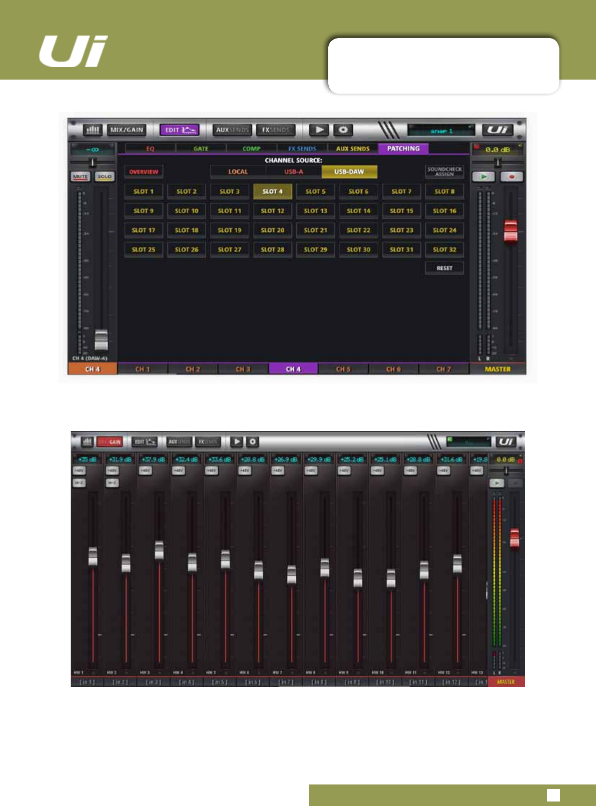
Ui24R User Manual 9.0.2: USB PLAYER & RECORDER
PLAYBACK & RECORDING FROM USB-DAW
Patching of USB-DAW can be done within an individual channels Patching Screen
9.0.2: USB PLAYBACK & RECORDING
USING THE USB-DAW PROCESSING AS AN INSERT WITHIN THE Ui24R
This screen allows the user to adjust the input level when they are using their DAW processing as an insert
on an input channel.
SELECTING INPUT CHANNELS ON YOUR DAW
When recording to DAW via USB
Channels 1 - 2 will be Master Left/Right fader
Channels 3 - 10 will be AUX 1-8
Channels 11 - 32 will be Channel 1 onwards
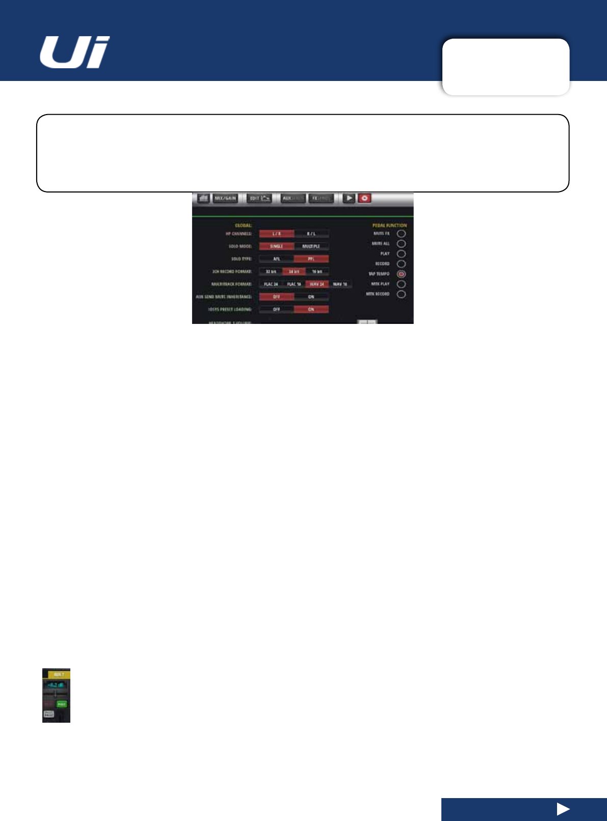
Ui24R User Manual 10.0: SETTINGS
SETTINGS
10.0: SETTINGS
TheSETTINGSpageallowstheusertomanagebasicsetupcongurations,networkparameters
(includingthepasswordsettingfortheWiFiaccesspoint),GUIpreferences,andaccesspermissions
on a per-user basis. Phone and tablet software versions display the settings in slightly different forms,
but al are accessible on either platform. The sub headings used in this section refer to the Tablet
software.
SETTINGS PRESETS
You can save your GUI settings to, and load your GUI settings from a USB memory stick by touching the PRESETS
button in the corner of the Settings page. This will open up a standard save / load screen.
GLOBAL
HEADPHONES OUT
HP CHANNELS
Select between L/R or R/L headphone split.
SOLO MODE
SINGLE, MULTIPLE
SINGLE deactivates any previous solo when a new one is pressed. MULTIPLE is an accumulative solo mode
(previoussolosarenotdeactivated).
SOLO TYPE
AFL, PFL
ChooseaSolotypeforchannelsolos.PFL(PreFadeListen)isa‘tap’beforethechannelfader,soyoucanmonitor
thechannelsignalwithouthavingtopushthefaderup.AFL(After-FadeListen)isatapafter(andaffectedby)the
channel fader.
2 TRK RECORD MODE
32-bit, 24-bit, 16-bit
Choose a sample rate for the media recording function.
AUX SEND MUTE INHERITENCE
Aux mute affecting global settings can be set to on or off in post mode only. The inheritance means taking
the mute button status from the main mixer to the Aux send as well or mute should be handled individually
ineachmixer(MainandAux)
HEADPHONE 1 and 2 VOLUME CONTROLLERS and SOLO level
The volume for Headphone out 1 and 2 can be controlled within the GUI. The headphone volume pot on
the interface controls the volume for Headphone 1 output only. Solo controls the level of Solo to the head-
phones
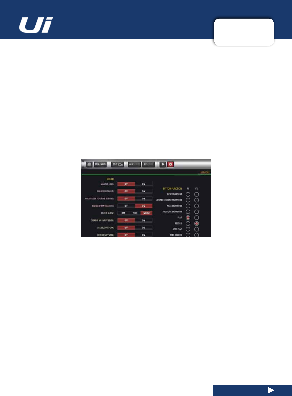
Ui24R User Manual 10.0: SETTINGS
SETTINGS
10.0: SETTINGS
GUI PERFORMANCE
FRAME RATE
FULL, 1/2, 13, 1/4
Choose the highest frame rate that your device can reproduce for best performance.
DISABLE RESCALING
ON, OFF
Enable/Disable display rescaling. Disable this if your display is struggling with GUI movements..
DISABLE LED METERS
OFF, ON
If you are using a slower CPU, you may wish to turn off the LED channel meters to reduce CPU usage.
LOCAL
MASTER LOCK
ON, OFF
When ON, the Master Channel fader is locked in place. Other parameters are still changeable.
HOLD FADER FOR FINE TUNING
OFF, ON
Allowfadernetuningmode.
METER QUANTISATION
OFF, ON
Choosebetweenquantisedmetering-ratherlikeanLEDbargraph-ornon-quantised(continuous).
FADERGLOW
OFF, THIN, NORM
Options for the coloured lines under the faders. 1. On, 2. Thin and 3. Off. These lines are handy to quickly
seewhichgroupoffadersyouareviewing(blueforFX,orangeforAUX,andsoon).

Ui24R User Manual 10.0: SETTINGS
SETTINGS
10.0: SETTINGS
DISABLE VU INPUT LEVEL
OFF,ON
Disable/Enable input level VU meters.
DISABLE VU PEAK
OFF, ON
Disable / Enable the peak indicators for VU meters.
HIDE COMP/GATE
OFF, ON
When off, the channel meters include shorter red LED gain reduction metering below the primary meters.
DIM LED METERS
OFF, ON
Turn on to lower the intensity of the metering colours.
PIN SLIDEOUT IN MIX MODE
OFF, ON
When this option is on, your mixer page will always display the Ui SlideOut without having to re-open it
each time you go back to the main mix screen.
PIN SO FOR AUX/FX SENDS
OFF, ON
When this option is on, your Aux Sends page will always display the Ui SlideOut without having to re-open
it each time you go to that screen.
KINETIC SCROLL
OFF, ON
Allow screen to continue scrolling after release. Ensure the screen is not scrolling for channel sub-menu
selection.
MIXER SCROLLING
1 FINGER, 2 FINGERS
Formorestabilityacrossthemixscreen,youcanyettheswipemodetotwongers.
PATTERNED BACKGROUND
OFF, ON
Enable, disable patterned background.
MOREME PORTRAIT MODE
OFF, ON
Enable,disable Moreme portrait mode.
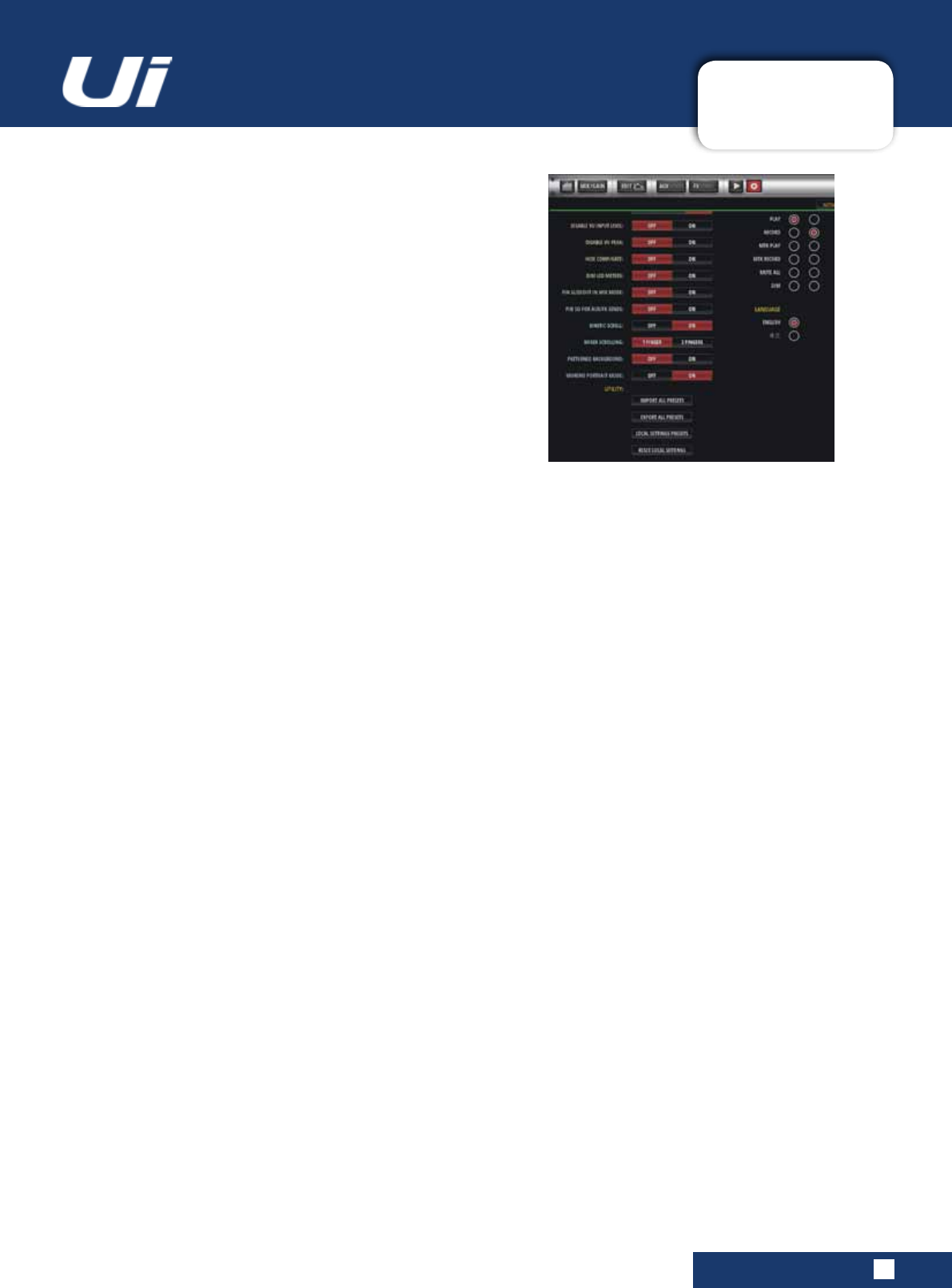
Ui24R User Manual 10.0: SETTINGS
SETTINGS
10.0: SETTINGS
PEDAL FUNCTION
MUTE FX
Enable pedal to mute FX
MUTE ALL
Enable pedal to mute all channels
PLAY
Enable pedal to activate USB playback
RECORD
Enable pedal to activate USB record
TAP TEMPO
Enable pedal to set delay tempo via tap tempo function
MTK PLAY
Enable pedal to activate MTK playback from USB or DAW
MTK RECORD
Enable pedal to activate MTK record to USB or DAW
BUTTON FUNCTION
F1, F2
NEW SNAPSHOT, UPDATE CURRENT SNAPSHOT, PLAY, RECORD, MTK PLAY, MTK RECORD
Choose functions to assign to the F1 and F2 buttons. On the tablet software these buttons appear at the top of the
MasterChannel.InthephonesoftwareonlyF1isavailable;F2isalwaystheMENUorRETURNbutton.
LANGUAGE
ENGLISH, CHINESE
The default language for Ui software is English, but here you can change to Chinese language version. The browser
will automatically refresh when these options are selected.
GLOBAL PRE-FADE AUX SEND POINT – PRE-PROCESSING OR POST-PROCESSING
TheAUXsendsignalcannowbedenedgloaballyasPre-ProcessingorPostProcessing.
Pre-Processing - The AUX send signal does not include any EQ/DYNAMICS that has been applied to the channel
Post-Processing - The AUX send signal includes any EQ/DYNAMICS that has been applied to the channel
Setting the GLOBAL AUX SEND POINT:
- Go to SETTINGS--SETTINGS tab page
Set the CLOBAL AUX SEND POINT option to PRE PROCESSING or POST PROCESSING
SYNC ID
Sync ID allows users to maintain channel sync across multiple browser windows/tabs on the same computer/device,
across different displays or even between devices.
YoucannowopenmultipleGUIwindowsinanyviewmode(MIX,EQ,DYN,FX,etc)andmaintainchannelsyncbe-
tween them once SYNC ID is enabled and set to the same nominal SYNC ID. Selection of a channel on any GUI page
will result in all other synced browser windows to update channel sync accordingly.
To enable Sync ID:
- Go to the SETTINGS-->SETTINGS tab page
-SettheSYNCSELECTEDCHANNELoptionto“ON”
-Click/tapinthe“SYNCID:”eldandsetanIDofyourchoice.Eg.“YourName”
-OpenanotherGUIonanotherdevice,browsertab,etc.EnableSYNCSELECTEDCHANNELandensureit’sSYNC
ID:isconguredtothesamenominalIDyouchoseontherstGUI.
You can now have different views on each of your tabs or devices that will remain in channel sync. Note that multiple
SYNCID’scanrunconcurrentlyontheUimixer.

Ui24R User Manual 10.0: SETTINGS
SETTINGS
10.0: SETTINGS
LOCAL USER GUI PRESETS
Local client side user settings can now be save/loaded as presets to connected media. This al-
lowsuserstochangedeviceswithease,takingtheirpredenedlocaluserpresetswiththem,
without having to set up their GUI every time they change devices!
Local client side GUI settings can be found in the SETTINGS-->SETTINGS tab page, under LO-
CAL. GUI options relating to a users client side application such as Pinning the slide out panel,
HidingtheComp/Gate,1or2ngerscroll,MOREMEportraitmode,etccannowbesavedasa
LOCAL SETTINGS PRESET.
To load/save/rename/delete LOCAL SETTINGS PRESETS:
- Go to the SETTINGS-->SETTINGS tab page
- Scroll down and click/tap the LOCAL SETTINGS PRESETS button
- Use the PRESETS manager to LOAD/SAVE/RENAME/DELETE your LOCAL SETTINGS PRE-
SETS to connected USB media
LOCAL USER GUI RESET TO DEFAULT
Local client side user settings can now be reset to default values.
To reset LOCAL SETTINGS to default value:
- Go to the SETTINGS-->SETTINGS tab page
- Scroll down and click/tap the RESET LOCAL SETTINGS button
- Local GUI settings will now be reset to default values and the GUI will be restarted automatically
MONITOR ACCESS LIMIT
This Tab/View manages access permissions - limiting feature access per user. Given that a typical setup may have
multiple users logged into the Ui software, each doing their own monitor mix, it makes sense to limit their access to
reduce the possibility of accidentally changing a front of house mix.
This feature is not password protected, it is intended as a safety measure to protect accidental corruption of your mix
by other users. It is especially helpful for setting up monitor permissions.
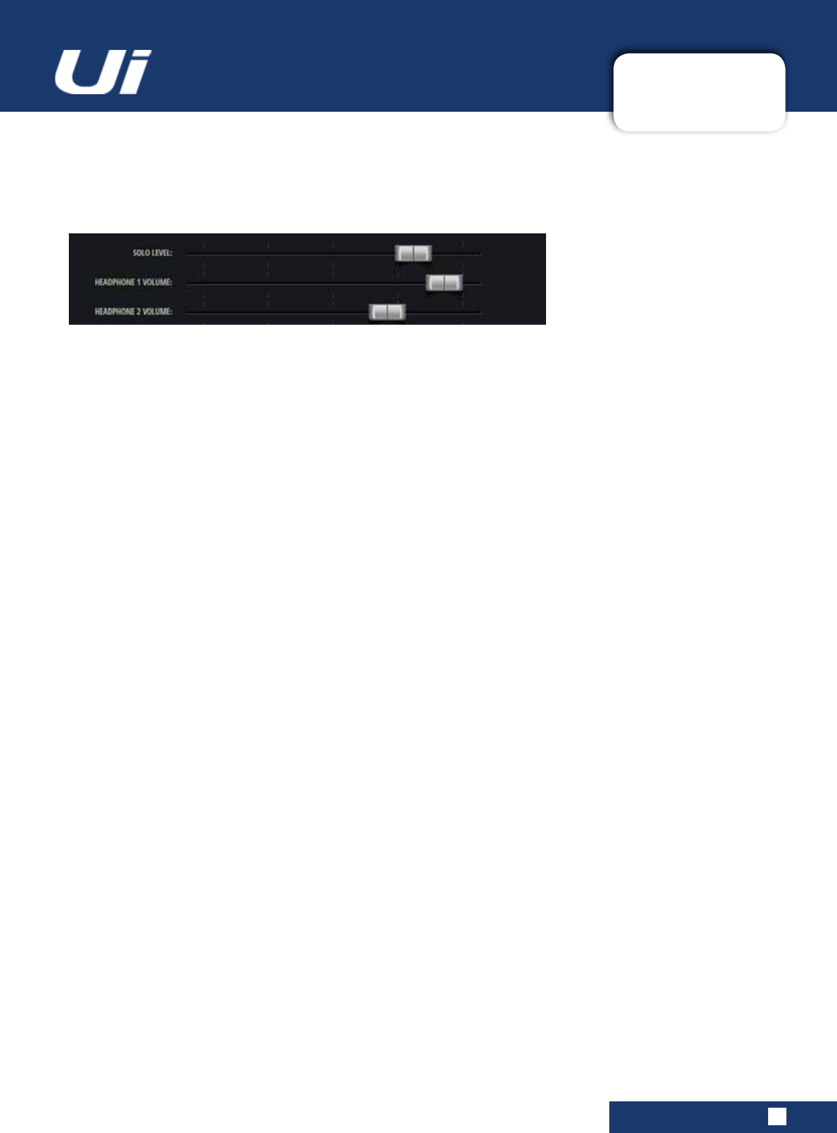
Ui24R User Manual 10.0: SETTINGS
10.0: SETTINGS
Solo and headphone levels
You can digitally set the output volume for Headphone 1 or 2 as well as the relative SOLO level.
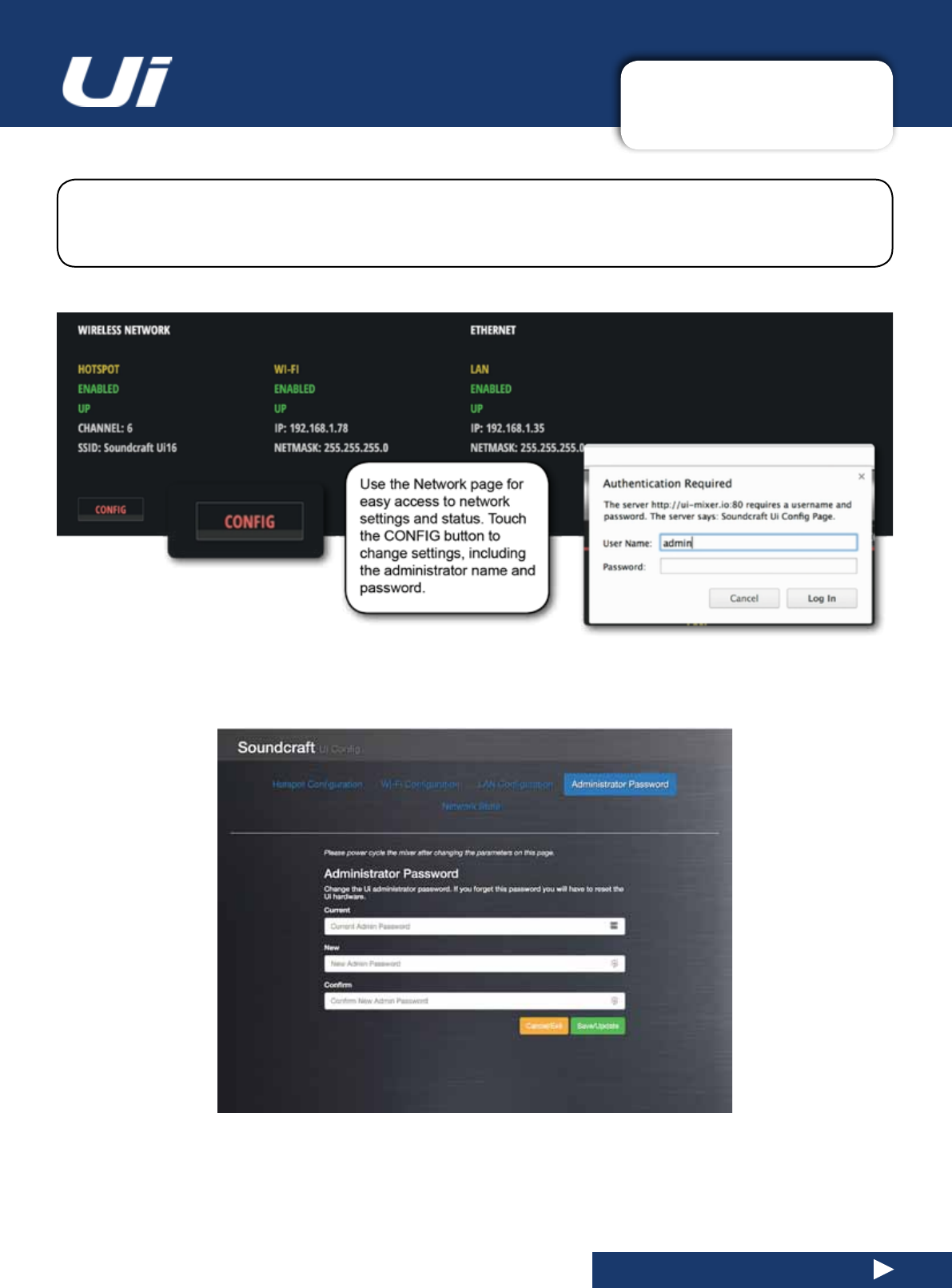
Ui24R User Manual 10.1: NETWORK CONFIG
SETTINGS > NETWORK CONFIG
10.1: NETWORK CONFIG
TheUiCongpageallowsyoutoenable/disableandeditsettingsforHotspotwirelessconnectionto
theUihotspot),WiFi(connectiontoanexistingWiFinetwork),andLAN(wiredconnectionviaEthernet).
ThereisalsoanAdministrationpasswordchangepage,andasummary‘NetworkState’page.
IMPORTANT:Thedefaultadministrationusernameis‘admin’andthedefaultadministrationpasswordis‘admin’.
You will be asked for these when you touch the CONFIG button. You can either use the UI24R as a hotspot or
connect to an external Wi network. LAN is available at anytime unless disabled.
You can change the password using the Administrator Password page once you are in the CONFIG area.
Inordertoresettheunit’snetworksettingsbacktothefactorydefaultsettingsyoucanusethehardwarereset
procedure, detailed in section 3.0.2.
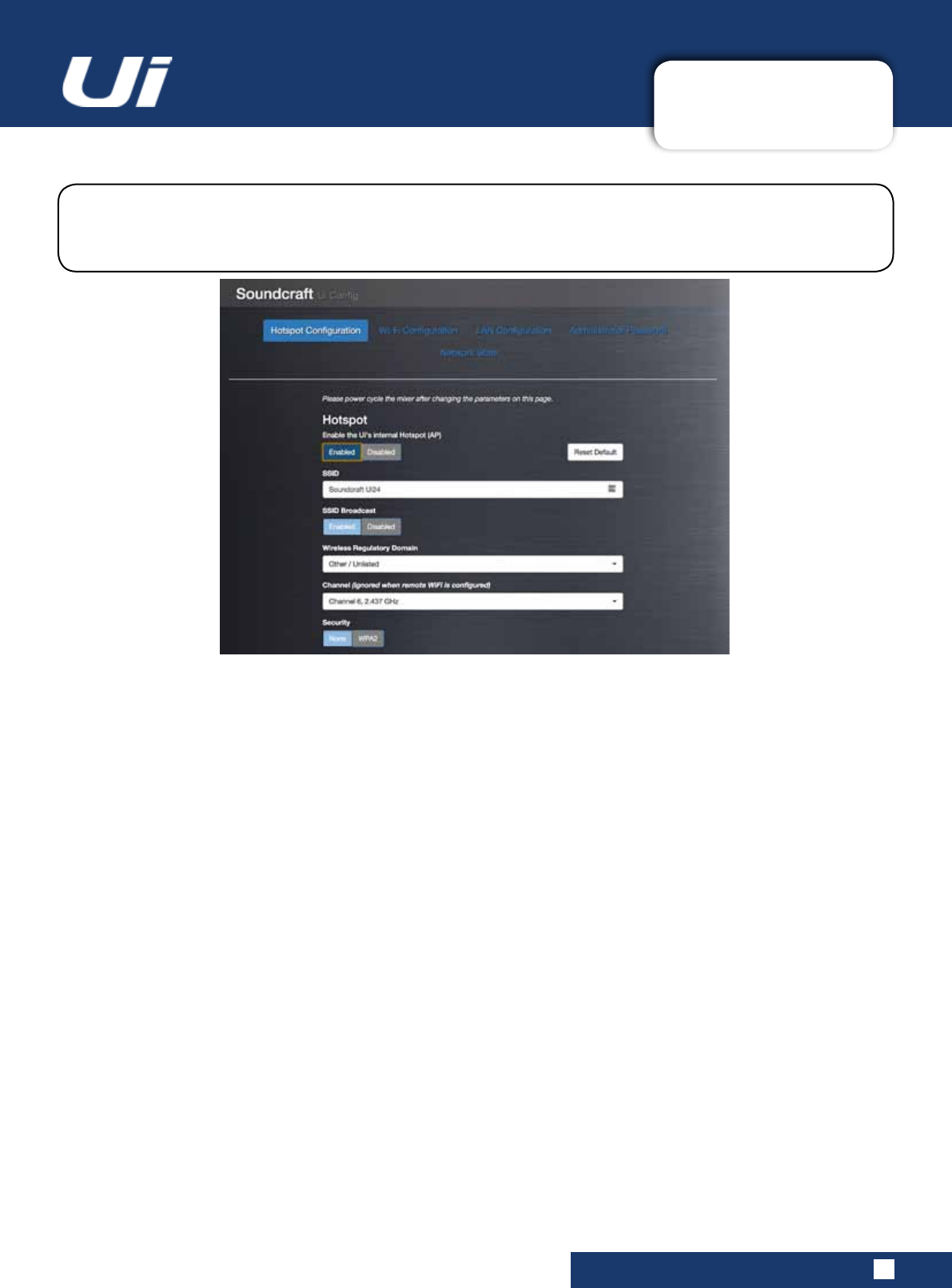
Ui24R User Manual 10.1.1: HOTSPOT
SETTINGS > NETWORK CONFIG > HOTSPOT
10.1.1: HOTSPOT SETTINGS
Use the Save/Update button to save Hotspot settings.
IMPORTANT: You cannot have both Hotspot and Client WIFI enabled at the same time.
TheUihasit’sownhotspot,soitcancreateit’sownnetworksootherdevicescanconnecttoitandac-
cessthesoftwareinit’sbuilt-inwebserver.SelecttheHotspotCongurationmenuinNetworkCongto
edit the Hotspot settings.
Hotspot
Enabled / Disabled
EnableordisabletheUI’sownHotspot.Pleasenote,iftheHotspotisdisabledyouwillneedtoconnecttotheUivia
eitheranexistingWi-Finetwork,orawiredLANconnection(Ethernet).
SSID (Service Set Identier)
Text Entry
ThisisthenameoftheUiHotspot.Thedefaultis‘SoundcraftUi’
Wireless Regulatory Domain
Region Selection
Select the correct region - your current location. This will help select the correct channel selection.
Channel
Channel Selection
A number of channels are available within the Wi-Fi spectrum, depending on the Regulatory Domain - 13 for Europe
(ETSI),and11forNorthAmerica(FCC),forexample.Third-partysoftwareisavailabletohelpselectWi-Fichannels.
Security
None / WPA2
Chooseeithernosecurity,orWPA2(Wi-FiProtectedAccessII)protection.INthelattercase,youwillhavetochoose
a password.

Ui24R User Manual 10.0.1: HOTSPOT
SETTINGS > NETWORK CONFIG > HOTSPOT
10.1.1: HOTSPOT SETTINGS
ENABLE/DISABLE BROADCAST OF THE UI’s HOTSPOT NETWORK SSID
There is now an option to enable or disable the broadcasting of the Ui networks hotspot SSID.
To enable/disable broadcast of the Ui’s hotspot SSID:
- Go to the SETTINGS-->NETWORK tab page
-SelectCONFIG(youmaybeedtologinwithyourAdmincredentials,Thedefaultisadmin/admin)
- Select HOTSPOT CONFIGURATION
- Set the SSID BROADCAST option to ENABLED or DISABLED
- Restart the Ui mixer for settings to take effect.
NETWORK INTERFACE MAC ADDRESS VISIBILITY
Network interace MAC addresses are now displayed in the web application GUI.
To view network interface MAC addresses:
- Go to the SETTINGS-->NETWORK tab page
- MAC addresses of active interfaces are displayed in the network details list of each interface.
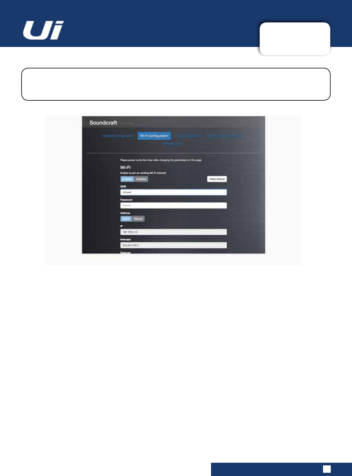
Ui24R User Manual 10.1.2: WI-FI
SETTINGS > NETWORK CONFIG > WI-FI
10.1.2: Wi-FI SETTINGS
Use the Save/Update button to save Wi-Fi settings.
IMPORTANT:YoumustrecycletheUipower(turntheunitoffandon)forsettingstotakeeffect.
The Ui can connect to an existing Wi-Fi network / Hotspot, and you can access the control software via
theunit’sIPnumber(showninSettings>Network).SelecttheWi-FiCongurationmenuinNetwork
CongtoedittheWi-Fisettings.
Wi-Fi
Enabled / Disabled
Enable or disable the Wi-Fi connection.
SSID (Service Set Identier)
Text Entry
This is the name of the network you wish to connect to.
Password
Text Entry
This is the password for the network you wish to connect to.
Master Password Protection
Address
DHCP / Manual
You can choose dynamic IP allocation, in which case the Ui will automatically allocate an IP, Netmask, and Gateway.
IfyouchooseManualIPallocation,youwillneedtocompletetheseeldsyourself.Pleaserefertoyournetwork
administrator for manual IP allocation.
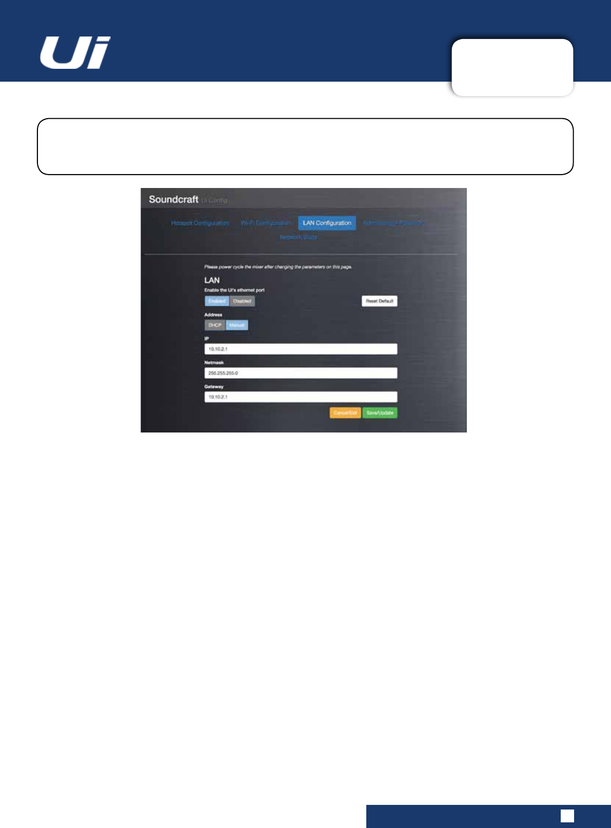
Ui24R User Manual 10.1.3: LAN
SETTINGS > NETWORK CONFIG > LAN
10.1.3: LAN SETTINGS
Use the Save/Update button to save LAN settings.
IMPORTANT:YoumustrecycletheUipower(turntheunitoffandon)forsettingstotakeeffect.
Default Settings
LAN IP: 10.10.2.1
Subnet mask: 255.255.255.0
Direct Connection
MostcomputerswithaGigaBitadapterwillAutoNegotiateandsowhenconnecteddirectlytotheunit(notviaa
switch)therewillbenoneedforanEthernetcrossovercable.UseastaticIPforthecomputer,inthesamerange
astheunit,suchas10.10.2.5andentertheIPaddressoftheunitinthecomputer’sbrowser.
TheUicanconnecttoanexistingwiredLAN(LocalAreaNetwork)byconnectiontheEthernetporton
the side of the unit. This is the fastest, most secure method of connection to the Ui. Select the LAN
CongurationmenuinNetworkCongtoedittheLANsettings.
LAN
Enabled / Disabled
EnableordisabletheUi’sEthernetport.
Address
DHCP / Manual
You can choose dynamic IP allocation, in which case the Ui will automatically allocate an IP, Netmask, and Gateway.
IfyouchooseManualIPallocation,youwillneedtocompletetheseeldsyourself.Pleaserefertoyournetwork
administrator for manual IP allocation.
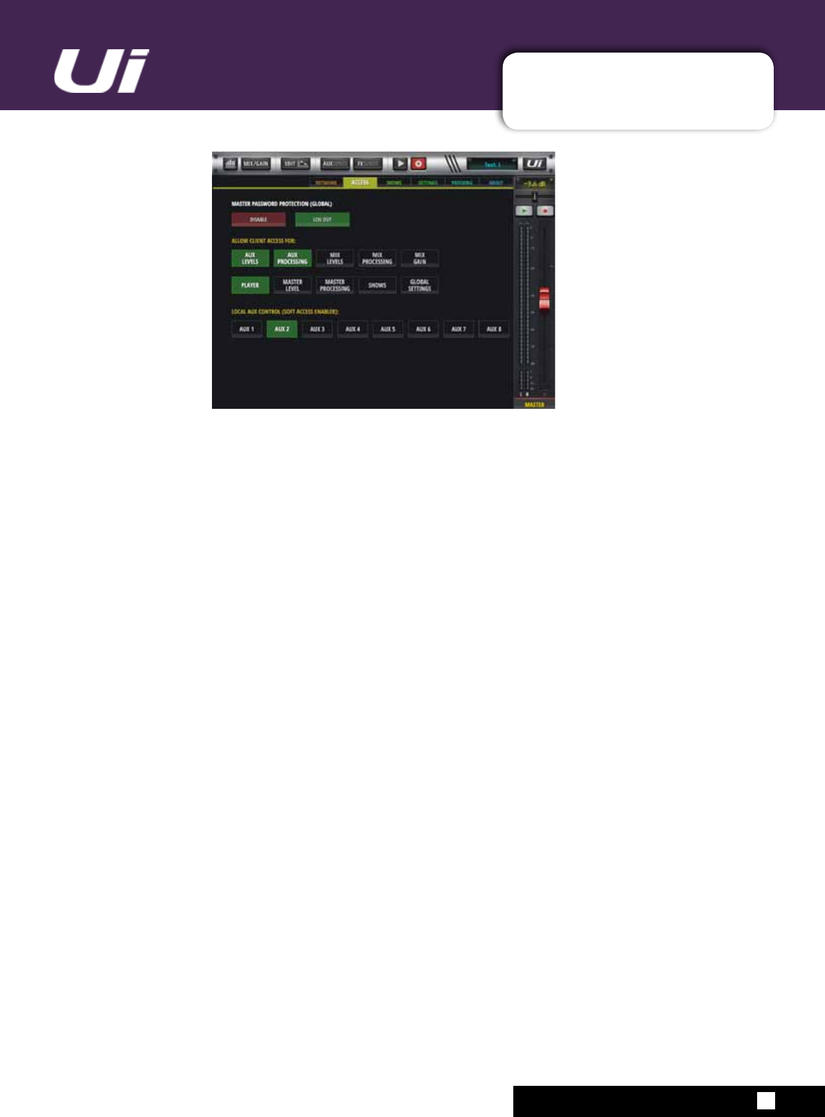
Ui24R User Manual MASTER PASSWORD
10.1.4 MASTER PASSWORD
HARD LOCK (ADMIN/PASS) ACCESS LIMITATIONS
A master password protection access limitation feature has been designed to allow a user logged in with
amasterpasswordtheabilitytodeneawiderangeofmixeraccesslimitationsforotherconnectedusers
(withoutknowledgeofthepassword.ienotloggedin).
Enabling MASTER PASSWORD PROTECTION:
- Go to SETTINGS-->ACCESS tab page
- Select the ENABLE button
- Set a master password of your choice to enable MASTER PASSWORD PROTECTION
Note: Enabling MASTER PASSWORD PROTECTION will automatically log a user in.
Disabling MASTER PASSWORD PROTECTION:
- Go to SETTINGS-->ACCESS tab page
- Select the DISABLE button
- Enter the master password to disable MASTER PASSWORD PROTECTION
LogginginandconguringALLOWCLIENTACCESSFOR:
AloggedinusercandeneGLOBALclientaccesslimitationsfornonloggedinusersbyallowingaccessto
certainpartsofthemixerasdenedbelow:
AUX LEVELS - AUX PROCESSING - MIX LEVELS - MIX PROCESSING - MIX GAIN - PLAYER - MASTER
LEVEL - MASTER PROCESSING - SHOWS - GLOBAL SETTINGS
LOCAL AUX CONTROL (SOFT ACCESS ENABLER)
AlocalclientsoftaccesseablerforAUXcontrolisprovidedfornonloggedinusers.Theusercandene
whichAUX’stheywanttocontrolifthemasterpassuserhasallowedaccessforeitherAUXLEVELSor
AUX PROCESSING.
Resetting a lost MASTER PASSWORD:
ToresetalostmasterpasswordtheusercanconnectaUSBdrivewithanemptylenamedmasterpass.txt
(topdirectory)andpowercycletheunitwiththeRESETbuttononthesideoftheunitdepressed.Holdthe
RESETbuttondpressedstateuntiltheblueWiFiledonthetoppannelstopsashing.TheMasterPassword
will be reset.
Ui24R User Manual APPENDIX 01: NO SOUND?
NO SOUND? A TROUBLESHOOTING GUIDE
APP01: NO SOUND?
A Troubleshooting Guide.
Oneofthemostcommonproblemsexperiencedwithmixingconsolesisndingthataninputisn’t
appearing at an output. There are many possible reasons for this, but the best way to troubleshoot it is
togothroughtheexpectedsignalpathandworkoutwherethe‘break’is...
It is also important that you double checking all routing, assignments, and Solo / Mute Group status.
You can check the exact audio path of any signal by referring to the input signal path diagram in
Section 2.3.
Are Solos inactive?
Checkfortheyellow‘S’isshownintheMasterChanneldisplayorayellowactivesoloindicatorinthe
DASHBOARD page, If a channel is soloed then all other channels may be muted.
Thisshouldn’taffectamainLeft/RightorMonooutputunlesstheMASTER+HPsolomodeisenabledinthe
SETTINGS.
Clear all active Solos either individually, or by using CLEAR SOLO in the DASHBOARD screen.
Check The input!
The physical input should be correctly connected. The physical input numbers correspond to the input channel
numbers in the Ui Control Software.
Is there anything on the meters?
By checking the Input and Output path meters, you should be able to localise a problem to a large extent.
The Input channel metering comes after the Mic/Line input but before the rest of the Input Channel. Therefore, if the input signal
is valid, and you have applied enough Gain, you should see a level indication on the input meters.
Output Channel metering is tapped just before the physical output.
Are they ‘in phase’?
Phase is only likely to cause an issue if coherent signals are applied to more than one channel and they are both
routed the same way. For example, you might be using a test signal, or using two channels for the same signal.
YoucancheckifphaseisanissuebyswitchingthePhase(GAINpage)onONEofthosechannels.Iftheaudiocomesback,
then look for the cause of the phase issue - it may be that a balanced connection has been wired incorrectly, for example.
Ui24R User Manual APPENDIX 01: NO SOUND?
NO SOUND? A TROUBLESHOOTING GUIDE
APP01: NO SOUND?
Is the Gate shut?
It is possible for an incorrectly set Gate process to stop all signal.
This happens most often when the threshold is set too high and the signal never gets loud enough to 'open' the Gate. You can
easilycheckthisbybypassingactiveGatesinthedynamics(DYN)tabofthechannelEDITpage.
Are there any active mutes?
The Ui allows you to mute channels individually, via Mute Groups, or via MUTE ALL and MUTE FX buttons the in
the DASHBOARD.
Mute Group operation is described in section 6.1.
Is the Fader up?
The channel fader needs to be set high enough when routing to any post-fade destination. If your problem output
route is pre-fader, then fader position will have no effect.
Is the Output Master Channel Path valid?
Almostexactlythesamechecksasabovecanbedoneonanoutputchannel(AuxSends,MasterOutput).
Run through the same checks as above but for the Output channel.
Is the Physical Output Valid?
Check the connection, and your replay system.
If metering is showing a valid output, it is likely there is a problem at, or after, the physical output.

Ui24R User Manual APPENDIX 02: SYSTEM FAQ
SYSTEM FAQ
APP02: SYSTEM FAQ
The Ui is not just an audio mixer - it is a WiFi hotspot and a web server, and it runs sophisticated
control software for phone and tablet-type devices. The following FAQ addresses any issues you might
havewiththis‘system’aspectofUioperation.
Q: How do I download the Ui app?
A: The Ui series mixers do not need an app. Simply connect to the your Ui mixer via Wi-Fi from any device
(PC,Tablet,Phone).StartanHTML5Browser(GoogleChrome,MozillaFirefox,Safari,etc.)andtypeinthe
followingURLintoyourbrowser:“ui-mixer.io”.Fromthere,chooseeithertheLargeinterface(PCortablet)
orSmallInterface(phones).
Q: Why does my iOS Wi-Fi keep changing to another network when my device goes to
sleep?
A: How iOS decides which wireless network to auto-join: https://support.apple.com/en-us/HT202831
YoucancongureyouriOSdevicetoautomaticallyjoinaspecicwirelessnetworkwithaprole.
BothAppleConguratorandOSXServerProleManagersupportthisoptionintheuserinterface.
https://support.apple.com/en-au/HT4989
Q: The GUI doesn’t work on my android device?
A: TheUiwebapplicationrequiresa‘modern’browserthatsupportsHTML5featureslikecanvasand
websockets. Android devices using the stock built in Android browser prior to Version 4.4 do NOT support
websockets, and as such will not function. We suggest upgrading your device to a more current version of
OS and browser. We also recommend installing and using the Chrome browser which fully supports
modern browser features.
Q: How do I operate fullscreen just like an app?
A (iOS):LaunchtheSafaribrowseronApple’siOSandnavigatetothewebsiteorwebpageyouwantto
addtoyourhomescreen.TaptheSharebuttononthebrowser’stoolbar—that’stherectanglewithan
arrowpointingupward.It’sonthebaratthetopofthescreenonaniPad,andonthebaratthebottomof
the screen on an iPhone or iPod Touch. Tap the Add to Home Screen icon in the Share menu.
A (Android): Launch Chrome for Android and open the website or web page you want to pin to your home
screen.TapthemenubuttonandtapAddtohomescreen.You’llbeabletoenteranamefortheshortcut
and then Chrome will add it to your home screen.
The icon will appear on your home screen like any other app shortcut or widget, so you can drag it around
andputitwhereveryoulike.ChromeforAndroidloadsthewebsiteasa‘webapp’whenyoutaptheicon,
soitwillgetitsownentryintheappswitcherandwon’thaveanybrowserinterfacegettingintheway.
Other popular Android browsers also offer this feature. For example, Firefox for Android can do this if you
tap the menu button, tap the Page option, and tap Add to Home Screen.

Ui24R User Manual APPENDIX 02: SYSTEM FAQ
SYSTEM FAQ
APP02: SYSTEM FAQ
A (Windows 8, 8.1, RT): Thisisobviouslymostusefulontablets,notondesktopPCswhereyoudon’t
want to see the Start screen. Navigate to the website you want to pin, pull up the app bar by right-clicking
or swiping up from the bottom of your screen and tap the star icon. Tap the pin icon, enter a name for the
shortcut, and click Pin to Start. The website will appear as a tile on your Start screen.
A (Windows Phone): OpenthewebsiteyouwanttopininInternetExplorer.TaptheMore(…)button
and tap Pin to Start in the menu that appears.
Q: Can I charge my USB device from the Ui’s USB ports?
A: Yes, the Ui hardware USB ports can be used as a device power source.
Q: Can I connect a more powerful antenna?
A: Sure,theincludedantennawillsufceformanyenvironments.Howeveritiseasilyscrewedoffandcan
be replaced with a larger. more powerful booster antenna.
Q: How do I reset a Ui mixer?
A: There are several reset modes:
Reset Networking and Admin password only If you have forgotten the admin password, For hotspot or
Wi-Fi settings you can simply use the reset button on the left hand side panel. Use a paper clip to hold the
resetbuttondownforapproximately10secondswhileyoupowerontheunit.ThiswillinitialisetheUi’snet-
working and admin password to the default state.
Reset to the default factory rmware
This method removes all updates you may have performed on the mixer and returns it to the default fac-
toryshippingrmwareandstate.Createatestlenamedfullreset.txt(nocontentsnecessary)andcopyto
aUSBstick.InserttheUSBstickintooneoftheUi’sUSBports.Useapapercliptoholdtheresetbutton
downforapproximately10secondswhileyoupowerontheunit.TheUiwillrecognisethefullreset.txtle
on the USB stick and perform a full factory reset.
Q: How long does the Ui take to bootup?
A: Approximately 20-22 seconds.
Q: How do I update the Ui’s rmware?
A:
1) DownloadtheUiupdatelefromthewebsite.Theformatis:uiupdate-1.0.3434-Ui24R.zip(leaveinzip
format)
2)CopytheletoaUSBmediadevicesuitableforconnectiontoaUimixersUSBport.Note:Thelecan
reside in any directory. Any USB port on the mixer is acceptable.
3) Ensure a client device is connected to the Ui mixer GUI
4)ConnectUSBmediatotheUimixer5/TheGUIdisplaywilldisplaythattheUSBdevicehasbeen
mounted.Afterthestickhasbeenread(maybe10moreseconds)theupdatewillberecognised.
5) The GUI will prompt you if you would like to update the Ui mixer. Options are Ok/Cancel.
6)SelectOKtoconrm

Ui24R User Manual APPENDIX 02: SYSTEM FAQ
SYSTEM FAQ
APP02: SYSTEM FAQ
7)TheUimixerwillperformarmwareupdate
8) The GUI will present a message stating whether the update has been successful or not.
9) You must power cycle the unit and reconnect their client device.
10)Youcannowbrowsetotheaboutpagetoseethenewrmwareversioninformation.
Q: How do I attenuate the media player input? It is really hot signal?
A: You can use adjust the Compressor Gain control down -24dB to compensate for the incredibly hot signal
thatmanyaudiolesaremasteredat.ThisadjustmentwillactlikeaPADandallowyouadditionalrangeon
the level fader to operate.
Q: Why are some elements of the GUI semi transparent (greyed out)?
A: Agreyedoutgraphicalcontrolelementisonethatisdisplayedwithalightshadeofgrey(orsemitrans-
parentstate),toindicatethatitiscurrentlydisabled,andcannotbeoperatedorselectedbytheuser.This
convention is widely used in graphical user interfaces, to visually indicate which actions cannot be taken in
the current situation. This approach makes it possible to disable a control when it cannot be used, and give
a clear signal of that state, while maintaining the graphical control element in a consistent location, thereby
minimising confusion for the user.
Q: Can I use the same USB stick for playback and recording?
A:ForFASTspeedUSBmediadevicesthiswillwork.ForinsufcientlyfastUSBstickstherecordermay
skip samples and record crackle.
Q: Why can’t I connect after changing the WPA password?
A: When changing network password it is recommended to always forget the corresponding WiFi network
connection on clients prior to attempting to rejoin. Certain devices cache network information and do not
allow connections after changing the WPA password until network is forgotten on client.
ItcansometimesalsobebenecialtodisableandthenenableyourWiFiadaptertoensurefreshclient
network information.
Q: Why do I have lost connections?
When using the mixer in highly populated WiFi environments or extended distance we recommend using a
high powered antenna or external router.

Ui24R User Manual APPENDIX 02: SYSTEM FAQ
SYSTEM FAQ-HDMI
APP02: SYSTEM FAQ
HDMI connection issues:
The Ui24R requires that HDMI connected components be able to recognize and communicate with each
other. Thisisreferredtoasthe“HDMIhandshake”.Ifthe“handshake”doesn’twork,theHDCPencryption
that is imbedded in the HDMI signal is not being recognized properly by one, or more, of the connected
components.
This most often results in not being able to see anything on your monitor.
Beforefrustrationsetsin,therearesomethingsyoucandoyourselfifyoundthatyourHDMI-connected
components are not communicating properly.
1. Try A Different Turn-on Sequence For Your Components:
Inotherwords,ifyouhaveahabitofturningonyourMonitprrst,thenyourUi24Rtrythereverse
turn on sequence and see if that works.
Ifyoundasequencethatworks,rememberit.Ofcourse,makesurewheneverythingisturned
on, and that you have selected the correct input on your monitor.
Once you have determined the best turn-on sequence - write it down for future reference.
2. Check Your Source Device’s Video Resolution Output Setting:
Ui24Routputresolutionisxedat720pcheckthatyourmonitorissettothesameresolutionas
well, most monitors automatically scale to the right resolution although some need manual selec-
tion.
3. Troubleshooting HDMI-to-DVI or DVI-to-HDMI Connection Problems
Another HDMI connection issue sometimes arises when it is necessary to connect an HDMI-en-
abled device to a TV or monitor that has a DVI connection, or a DVI-enabled source device to an
HDMI-equipped TV.
Inthiscase,youneedtouseanHDMI-to-DVIconversioncable(HDMIononeend-DVIonother
other)oruseanHDMIcablewithanaddedHDMI-to-DVIadapteroraDVIcablewithaDVI-to-
HDMI adapter. Check out examples of DVI/HDMI adapters and cables on Amazon.com
The added requirement is that the DVI-equipped device you are connecting is HDCP-enabled.
This allows the proper communication between both the HDMI and DVI devices.
Ordinarily, there should not be a problem converting HDMI to DVI, but there can be. For example,
youwillndthat3Dand4Ksignalsarenotcompatible.Withstandard480p,720p,or1080preso-
lution video signals.
On the other hand, you can also run into a situation on older-DVI equipped TVs that even if they
areHDCPcompliant,theymaynothavetheproperrmwaretorecognizetheidentityoftheHDMI
source component you are trying to connect.
An ACTIVE HDMI to DVI or HDMI to VGA adapter normally works better than a passive one.
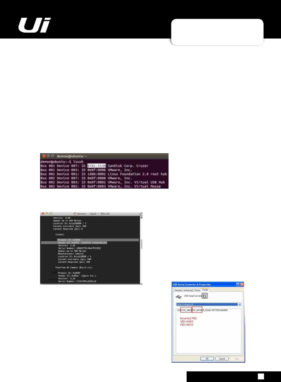
Ui24R User Manual APPENDIX 02: SYSTEM FAQ
SYSTEM FAQ-Touch screen
APP02: SYSTEM FAQ
Touch connection issues:
The Ui24R requires that the touch screen information be passed via a USB cable to one of the USB A con-
nections.
Eachscreenhasit’sownUSBIDnumbercalledVIDandPID,insomeinstanceseventhesamemodel
may have a different VID and PID depending on which country it was purchased from.
WehaveimplementedseveralsuchID’sintheUi24RbutitisimpossibleforustoknowalltheIDnumber
and all the screen that may be available at a future time.
In such cases please contact support and email your VID and PID, Screen model and version to Soundcraft
supportsowecanaddittothermwareoftheUi24R.
Linux:Justrunintheterminalandnddetailsofyourstick
lsusb
MAC OS:
system_prolerSPUSBDataType
Windoes PC:
Openthe“DeviceManager”.
FindtheUSBdevice,VIDandPIDwhichyouwanttodene.
Afterclickingtherightbutton,select“Properties”
Intheresultingwindow,selectthetab“Data”and,
if necessary,
choosefromthedrop-downlistline“DeviceInstanceId”
Please email this information to the Soundcraft Support email
address.

Ui24R User Manual APPENDIX 02: SYSTEM FAQ
Setting up a connection
APP02: SYSTEM FAQ
AlthoughtheUi24RhasWiconnectivity,caremustbetakeninusingsuchaconnectionwhereinterfer-
ence can occur and longer distance control is required.
In such situations it is recommended to use a more powerful external router with larger antennas or use an
Ethernet connection directly to the Ui24R.
UsingaWiscannerapplicationyoushoulddeterminewhichchannelsarefreeinyourareaandsetthe
Ui24R to use one of these channels.
YoushouldalsohaveadirectlineofsighttotheWiAntennaoftheUi24Rorrouteryouareusing.
DOM 18 error
IfyouaregettingthefollowingerrormessagewhenconnectingtotheUimixer’shotspotviaipad:498
SecurityerrorDOMexception18.Anattemptwasmadetobreakthrusecuritypolicyofuseragent.It’s
probably caused while running on SAFARI in IOS, in Safari, this likely means that your browser is currently
blocking cookies that are necessary for LastPass to work. Please enable cookies by going to Safari Prefer-
ences>Privacy>CookiesandWebsitedata>choose‘AlwaysAllow’.RestartSafariandtryagain.
How do I operate fullscreen just like an app?
iOS
LaunchtheSafaribrowseronApple’siOSandnavigatetothewebsiteorwebpageyouwanttoaddtoyour
homescreen.TaptheSharebuttononthebrowser’stoolbar—that’stherectanglewithanarrowpointing
upward.It’sonthebaratthetopofthescreenonaniPad,andonthebaratthebottomofthescreenonan
iPhone or iPod Touch. Tap the Add to Home Screen icon in the Share menu.
Android
Launch Chrome for Android and open the website or web page you want to pin to your home screen. Tap
themenubuttonandtapAddtohomescreen.You’llbeabletoenteranamefortheshortcutandthen
Chrome will add it to your home screen.
The icon will appear on your home screen like any other app shortcut or widget, so you can drag it around
andputitwhereveryoulike.ChromeforAndroidloadsthewebsiteasa“webapp”whenyoutaptheicon,
soitwillgetitsownentryintheappswitcherandwon’thaveanybrowserinterfacegettingintheway.
Other popular Android browsers also offer this feature. For example, Firefox for Android can do this if you
tap the menu button, tap the Page option, and tap Add to Home Screen.
Windows 8, 8.1, RT
Thisisobviouslymostusefulontablets,notondesktopPCswhereyoudon’twanttoseetheStartscreen.
Navigate to the website you want to pin, pull up the app bar by right-clicking or swiping up from the bottom
of your screen and tap the star icon. Tap the pin icon, enter a name for the shortcut, and click Pin to Start.
The website will appear as a tile on your Start screen.
Windows Phone
OpenthewebsiteyouwanttopininInternetExplorer.TaptheMore(…)buttonandtapPintoStartinthe
menu that appears.