Harrington Hoists Personal Lift Mr2 Users Manual
TS2 to the manual 8fcba9a4-6a26-419a-bfbb-7ce3e4788307
2015-02-09
: Harrington-Hoists Harrington-Hoists-Harrington-Hoists-Personal-Lift-Mr2-Users-Manual-564037 harrington-hoists-harrington-hoists-personal-lift-mr2-users-manual-564037 harrington-hoists pdf
Open the PDF directly: View PDF ![]() .
.
Page Count: 64
- IMPORTANT INFORMATION ON HOW TO USE THIS MANUAL
- Main Table of Contents
- I Conformance Clarification Statement
- II NER2 Electric Chain Hoist
- 1.0 Important Information and Warnings ……………………………………………………………..…….ER2OM
- 6.0 Maintenance & Handling ……………………………………...…………………………………………ER2OM
- 7.0 Troubleshooting ………………………………………………………………………………………….ER2OM
- 8.0 Warranty ………………………………………………………………………………………………….ER2OM
- 9.0 Parts List ………………………………………………………………………………………………………... 21
- Table 2-2 Hoist Dimensions
- III MR2 Motorized Trolley
- IV TS2 Manual Trolley
- 10.3 Hook Parts
- V Parts List
- 10.3 Hook Parts
- 10.3 Hook Parts
- 10.3 Hook Parts
--
ELECTRIC
CHAIN HOIST
NER2 / MR2 / TS2
FOOD GRADE MODEL
1/4 Ton through 2 Ton Capacities
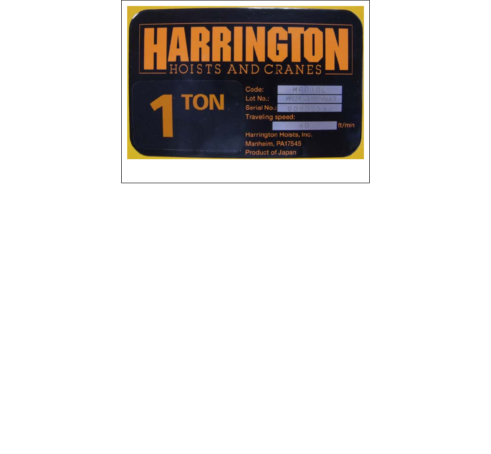
Code, Lot and Serial Number
This equipment should not be installed, operated or
maintained by any person who has not read and understood
all the contents of this manual. Failure to read and comply
with the contents of this manual can result in serious bodily
injury or death, and/or property damage.
EFFECTIVE: March 11, 2013

2
IMPORTANT INFORMATION ON HOW TO USE THIS MANUAL
This OWNER’S MANUAL SUPPLEMENT for Food Grade Hoists is intended for use in combination with:
“Owner’s Manual for Electric Chain Hoist ER2 and NER2 Series 1/8 through 5 Ton Capacity”
“Owner’s Manual for Motorized Trolley MR2 Series 1 Ton through 20 Ton Capacity”
“Owner’s Manual for Manual Trolley TS2/TF2 Series ½ Ton through 5 Ton Capacity”
Refer to the Main Table of Contents below to determine the location(s) of information pertaining to your hoist.
References to the Owner’s Manuals listed above will be designated by the use of the acronym “ER2OM”, “MR2OM”,
“TF2TS2OM”.
Main Table of Contents
Chapters Page Number
I Conformance Clarification Statement…………………………………………3
II NER2 Electric Chain Hoist………………………………………………..……….4
III MR2 Motorized Trolley……………………………………………………..……..11
IV TS2 Manual Trolley……………………………………………………..…………15
V Parts List……………………………………………………………………………..21
1.0 NER2……………………………………………………………………………..21
2.0 MR2……………………………………………………………………………….43
3.0 TS2………………………………………………………………………………..59

3
I Conformance Clarification Statement
1.1 Food Grade Options
Harrington ER2 Food Grade hoists are designed for applications which require food grade hoists. All
products should be tested for suitability on a particular application prior to actual use. The
occupational Safety and Health Act of 1970 places the burden of compliance with the
owner/employer, not the manufacturer. Many OSHA requirements are not concerned or connected
with the manufactured product but are associated with the final installation. It is the owner’s
and user’s responsibility to determine the suitability of a product for any particular use. It is
recommended that all applicable industry, trade association, federal, state and local regulations be
checked. Read all operating instructions and warnings before operation.
1.2 Corrosion Resistance:
Standard Product Features and Benefits
• Nickel plated load chain
• The formulation of NEVASTANE HT/AW WHITE greases complies with the FDA chapter
21 CFR, 178.3570.
• The formulation of NEVASTANE SL oils complies with the FDA chapter 21 CFR,
178.3570.
• White epoxy painted hoist body, hooks, and suspenders
• ASME H4 classification
• Stainless steel and nickel plated components
Optional Product Features and Benefits
• Nickel Diffused Load Chain
• Stainless Steel Trolley Wheels
• Nickel Plated shafts and suspenders
• NEMA 4 pendant
• Pendant Cover
• Stainless Steel bottom hook
• Stainless Steel chain spring and limiting plate
• Stainless Steel chain container

4
II NER2 Electric Chain Hoist
Section Page Number
1.0 Important Information and Warnings ……………………………………………………………..…….ER2OM
1.1 Terms and Summary
1.2 Warning Tags and Labels
2.0 Technical Information…………………………………………………………………………...……………6
2.1 Specifications
2.2 Dimensions
3.0 Preoperational Procedures …………………………………………………………………………..ER2OM
3.1 Gearbox
3.2 Chain
3.3 Mounting Location
3.4 Mounting the Hoist
3.5 Electrical Connections
3.6 VFD Setup (Dual Speed Only)
3.7 Preoperational Checks and Trial Operation
4.0 Operation …………………………………………………………………..……………………….....ER2OM
4.1 Introduction
4.2 Shall’s and Shall Not’s for Operation
4.3 Hoist Controls
5.0 Inspection ……………………………………………………………………………………..…..….. ER2OM
5.1 General
5.2 Inspection Classification
5.3 Frequent Inspection
5.4 Periodic Inspection
5.5 Occasionally Used Hoists
5.6 Inspection Records
5.7 Inspection Methods and Criteria

5
Section Page Number
6.0 Maintenance & Handling ……………………………………...…………………………………………ER2OM
6.1 Count/Hour Meter
6.2 Lubrication – Load Chain, Hooks and Suspension………………………..….8 and ER2OM
6.3 Lubrication – Gearbox…………………………………………………….....…..8 and ER2OM
6.4 Motor Brake
6.5 Load Chain……………………………………………………………………....10 and ER2OM
6.6 Friction Clutch and Mechanical Load Brake with Friction Clutch
6.7 Storage
6.8 Outdoor Installation
6.9 Operational Environment
7.0 Troubleshooting ………………………………………………………………………………………….ER2OM
8.0 Warranty ………………………………………………………………………………………………….ER2OM
9.0 Parts List ………………………………………………………………………………………………………... 21
6
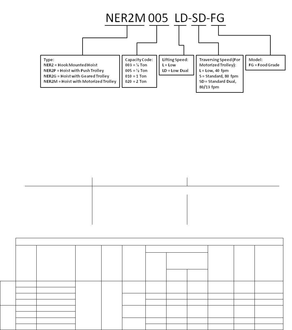
2.1 Specifications
2.1.1 Product Code
2.1.2 Operating Conditions and Environment
Temperature range:
-4° to +104°F (-20° to +40°C)
Humidity:
85% or less
Noise Level:
85 dB or less (A scale: measured 1 meter away from electric chain hoist
Enclosure Rating:
Hoist Meets IP 55
Supply Voltage: Single Speed Standard: Reconnectable 208/230-3-60 & 460V-3-60
Dual Speed Standard: 208/230V-3-60 or 460V-3-60
Single Speed Dual Speed
Hoist Duty Rating:
ISO M4/M5; ASME H4
Intermittent Duty
Rating:
60% ED
360 starts per hour
40/20% ED
120/240 starts per hour
Short Time Duty
Rating:
60 min. 30/10 min.
Table 2-1 Hoist Specifications
Cap.
(Tons) Product Code Standard
Lift
(ft)
Push
Button
Cord
L
(ft)
Lifting
Speed
(ft/min)
Lifting Motor 3 Phase 60 Hz Load
Chain
Diameter
(mm)
x
Chain Fall
Lines
Net
Weight
(lbs)
Weight for
Additional
One Foot
of Lift
(lbs)
Output
(Hp)
Rated Current
(amps)
@208 -
230V @460V
Single
Speed
1/4
NER2003L-FG
10 8.2
15 0.75 3.4 1.7 6.0 x 1 71 0.54
1/2
NER2005L-FG
1
NER2010L-FG
14
1.2
4.8
2.5
7.7 x 1
104
0.89
2
NER2020L-FG
2.4
8.6
4.2
10.2 x 1
161
1.6
Dual
Speed
1/4
NER2003LD-FG
15/2.5 0.75 3.6 1.8 6.0 x 1 68 0.54
1/2
NER2005LD-FG
1
NER2010LD-FG
14/2.5
1.2
5.1
2.7
7.7 x 1
99
0.89
2
NER2020LD-FG
2.4
9.1
4.5
10.2 x 1
161
1.6
7
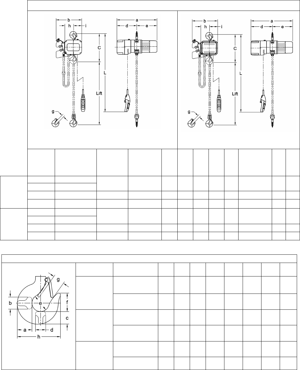
2.2 Dimensions
Table 2-2 Hoist Dimensions
Figure 2-1 Single Speed Hoist Dimensions
Figure 2-2 Dual Speed Hoist Dimensions
Capacity
(Tons) Product Code Headroom
C
(in)
Headroom
w/Stainless
Hook C
(in)
a
(in)
b
(in)
d
(in)
e
(in)
g
(in)
g
w/Stainless
Hook
(in)
h
(in)
i
(in)
Single
Speed
1/4
NER2003L-FG
14.6 17.7 20.2 13.7 9.5 10.6 1.1 1.2 4.4 4.2
1/2
NER2005L-FG
1 NER2010L-FG 16.9 21.2 23.2 14.8 11.4 11.7 1.2 1.5 5.1 4.6
2 NER2020L-FG 22.6 23.4 25.4 16.8 12.1 13.3 1.6 1.7 6.3 5.4
Dual
Speed
1/4
NER2003LD-FG
14.6 17.7 22.4 13.7 11.8 10.6 1.1 1.2 4.4 4.2
1/2
NER2005LD-FG
1
NER2010LD-FG
16.9
21.3
24.1
14.8
12.4
11.7
1.2
1.5
5.1
4.6
2 NER2020LD-FG 22.6 23.4 27.9 16.8 14.6 13.3 1.6 1.7 6.3 5.4
Table 2-3 Hook Dimensions
T = Top Hook
B = Bottom Hook
Capacity Code Hook a
(in) b
(in) c
(in) d
(in) e
(in) f
(in) g
(in) h
(in)
003L, 005L,
003LD, 005LD
Stainless Bottom 1.5 0.9 1.2 0.9 1.7 1.8 1.2 4.3
Epoxy Painted
Top & Bottom 1.1 0.7 0.9 0.7 1.4 1.5 1.1 3.7
010L, 010LD
Stainless Bottom 1.9 1.1 1.6 1.1 2.0 2.2 1.5 5.4
Epoxy Painted
Top & Bottom 1.5 0.9 1.2 0.9 1.7 1.8 1.2 4.3
020L, 020LD
Stainless Bottom 2.2 1.4 1.9 1.4 2.4 2.5 1.7 6.3
Epoxy Painted
Top & Bottom 2.0 1.3 1.7 1.3 2.1 2.2 1.5 5.7
8
6.2 Lubrication – Load Chain, Hooks, and Suspension
6.2.1 Load Chain
• For longer life, the load chain should be lubricated.
• The load chain lubrication should be accomplished after cleaning the load chain with an acid
free cleaning solution.
• Apply only Harrington Hoist, Inc. food grade lubricant (Part No. 2AFG003S1951) to the bearing
surfaces of the load chain links as indicated by the shaded areas in Figure 6-2. Also apply the
lubricant to the areas of the load chain (shaded areas in Figure 6-2) that contact the load
sheave. Ensure that the lubricant is applied to the contact areas in the load sheave pockets.
Figure 6-2 Chain Grease Application
• The load chain should be lubricated every 3 months (more frequently for heavier usage or
severe conditions).
6.2.2 Hooks and Suspension Components
• Hooks – Bearings should be cleaned and lubricated at least once per year for normal usage.
Use only Nevastane HT/AW 2 White Drum food grade lubricating grease. Clean and lubricate
more frequently for heavier usage or severe conditions.
• Suspension Pins – Lubricate at least twice per year for normal usage; more frequently for
heavier usage or severe conditions.
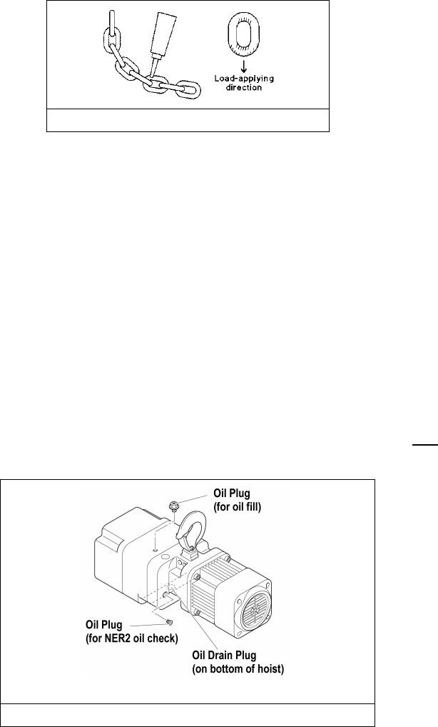
6.3 Lubrication - Gearbox
6.3.2 DETERMINING OIL LIFE - Refer to Section 6.1.3 in the ER2OM when estimating gear oil life
based on operations.
6.3.3 NER2 OIL LEVEL – The oil level is checked by removing the oil plug on the side of the hoist as
shown in Figure 6-3 for NER2 hoists. The oil level should be just below the hole when the hoist is
level.
NER2 Hoists
Figure 6-3 Oil Plug Locations
9
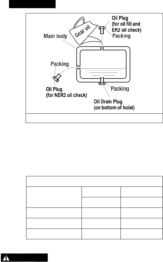
6.3.5 REPLACING OIL – Change gear oil at least once every 5 years. The oil should be
changed more frequently depending on the hoist's usage and operating environment. Refer to
Section 6.1.3. Follow the procedure below for replacing the gearbox oil for your hoist:
• To drain the current oil from the hoist remove “Oil Plug” on top of the hoist and the “Oil
Drain plug” on the bottom of the hoist. Allow the old oil to drain completely. Refer to
Figure 6-4 for oil plug locations.
•
Dispose of the used oil in accordance with local regulations.
Figure 6-4
Oil Filling Diagram
• Ensure that the oil plugs for the oil level check holes and the drain hole are reinstalled
and secured into the hoist body.
• Refill the gear case with the correct quantity and type of new oil or until the oil level is
within the range shown in Table 6-6. Refer to Figure 6-4.
Table 6-6 Amount of Gear Oil
Capacity Code Quarts Liters
NER2 NER2
003L/005L 0.57 0.54
010L 0.66 0.62
020L 1.37 1.30
Using an incorrect type/grade of gearbox oil or the wrong quantity of oil
may prevent the friction clutch from working properly and may affect the ability of the hoist to
hold the load. Only lubricants with NSF H1 compliance may be used in food grade hoists.
Refer to the following for the correct type of gearbox oil:
NER Gear Oil:
Harrington standard: Nevastane SL 320 (Total Lubricants)
10
6.5 Load Chain
6.5.2 After chaining a unit, be sure to clean any exposed portions of bottom yoke bolts that have been
treated with thread locking compound. Conduct a thorough inspection of these bolts after
torquing to ensure there is no excess thread locking compound on the exposed portions. Failure
to do so could affect the hoist’s compliance with the application’s food grade requirements.

11
III MR2 Motorized Trolley
Section Page Number
1.0 Important Information and Warnings………………...……………………………………….....….MR2OM
1.1 Terms and Summary
1.2 Warning Tag and Labels
2.0 Technical Information…………………………………………………….………….…………………..….13
2.1 Specifications
2.2 Dimensions
3.0 Pre-operational Procedures..……………………………………………………………................MR2OM
3.1 Assembly and Adjustment
3.2 Mounting Location
3.3 Installation of Trolley onto Beam
3.4 Electrical Connections
3.5 VFD Setup (Dual Speed Only)
3.6 Pre-operational Checks and Trial Operation
4.0 Operation………………………………………………………………………………………………MR2OM
4.1 Introduction
4.2 Shall’s and Shall Not’s for Operation
4.3 Trolley and Hoist Controls
5.0 Inspection………………………………………………………………………..…………………….MR2OM
5.1 General
5.2 Inspection Classification
5.3 Frequent Inspection
5.4 Periodic Inspection
5.5 Occasionally Used Trolleys
5.6 Inspection Records
5.7 Inspection Methods and Criteria

12
Section Page Number
6.0 Maintenance & Handling……………………………………………………………………………..MR2OM
6.1 Count/Hour Meter (Dual Speed Only)
6.2 Lubrication……………………………………………………..………………..14 and MR2OM
6.3 Brake
6.4 Storage
6.5 Outdoor Installation
6.6 Operational Environment
7.0 Troubleshooting……………………………………………………..………………………………..MR2OM
8.0 Warranty……………………………………………………………...………………………………. MR2OM
9.0 Parts List……………………………………………………………………………………………………...43
13
2.0 Specifications
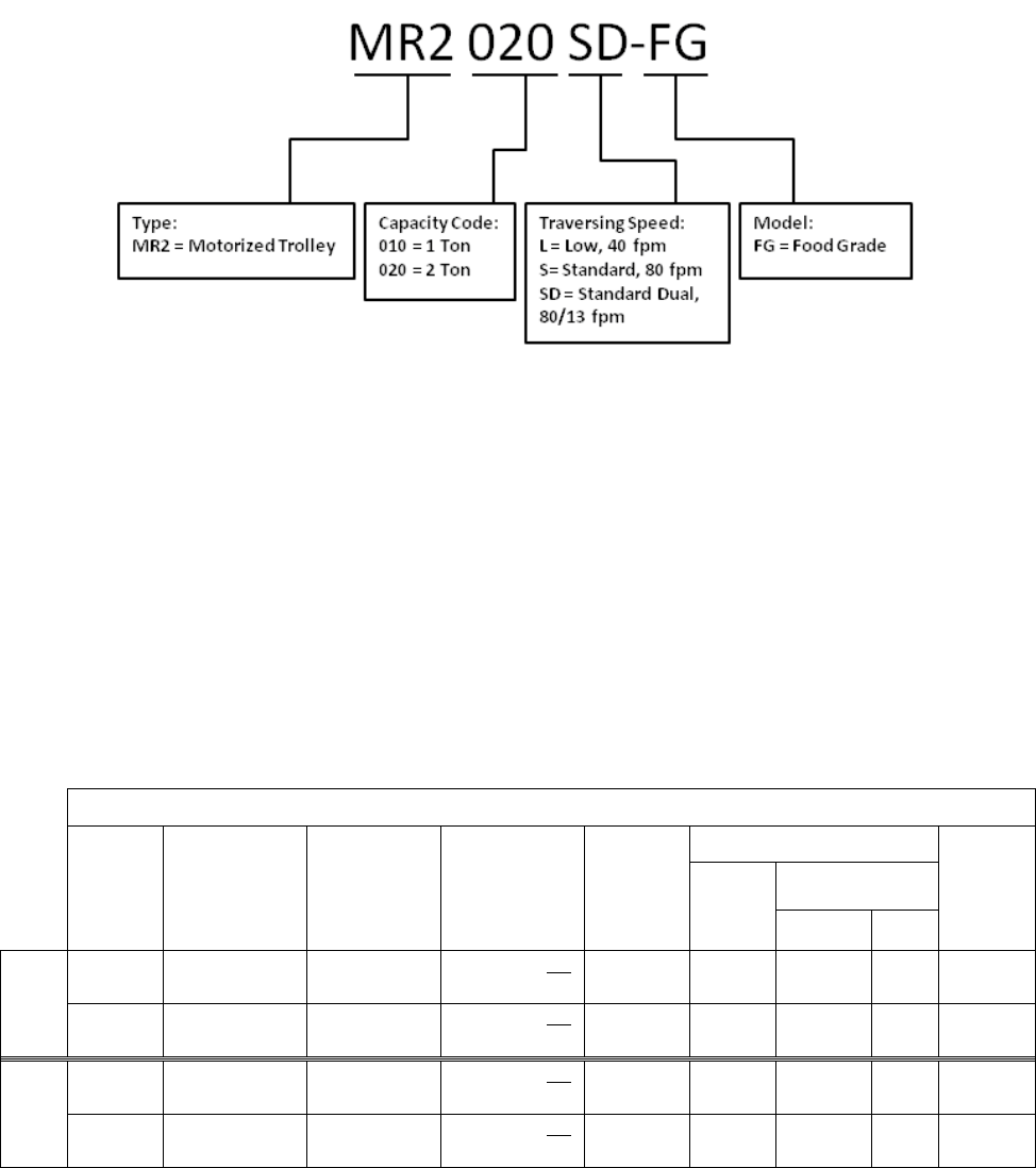
2.1.1 Product Code for MR2 Trolley Alone:
2.1.2 Operating Conditions and Environment
Temperature Range:
-4° to +104°F (-20° to +40°C)
Humidity:
85% or less (no condensation)
Noise Level: 85 dB or less (A scale: measured 1 meter away from the electric chain
hoist)
Enclosure Rating:
Trolley Meets IP55, Pendant Meets IP 65
Supply Voltage: Standard 208-230/460V-3-60, Optional 575V-3-60, Special Voltages
Available
Intermittent Duty Rating: Single Speed – 40% ED 240 starts per hour
Dual Speed – 27/13% ED with 78/162 starts per hour
Trolley Duty Rating:
ISO M4/5; ASME H4
Table 2-1 Trolley Specifications
Capacity
(Ton) Product Code
Standard
Beam Flange
Range
(in)
Optional Beam
Flange Range
(in)
Min.
Allowable
Radius
for Curve
(in)
Motor*** Approx.
Net
Weight
(lbs)
Output
(Hp)
Current Draw
(amps)
208V or
230V
460V
Single
Speed
1 MR2010L/S-FG 2.28 to 5.00 5.01 to 6.02 OR
6.03 to 12.00 31.5* 0.54 3.0 1.5 68
2 MR2020L/S-FG 3.23 to 6.02 6.03 to 7.02 OR
7.03 to 12.00
31.5** 0.54 3.0 1.5 84
Dual
Speed
1 MR2010SD-FG 2.28 to 5.00 5.01 to 6.02 OR
6.03 to 12.00
31.5 0.54 3.0 1.5 75
2 MR2020SD-FG 3.23 to 6.02 6.03 to 7.02 OR
7.03 to 12.00 31.5 0.54 3.0 1.5 93
14
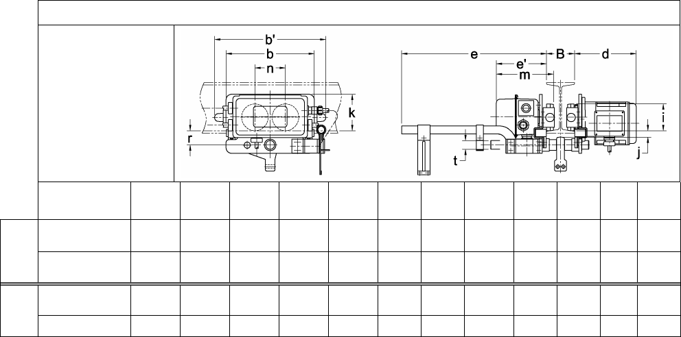
2.2 Dimensions
Table 2-2 Trolley Dimensions
For NER2003L-FG to
NER2020L-FG
Product
Code b b' d e e' i j k m n r t
Single
Speed
MR2010L/S-FG 12.4 15.6 8.7 20.3 7.1 3.74 0.9 5.1 8.1 4.3 2.0 1.22
MR2020L/S-FG 12.8 16.4 8.9 20.5 7.2 4.33 1.1 4.9 8.4 4.7 2.4 1.42
Dual
Speed
MR2010SD-FG 12.4 15.6 8.7 20.3 7.1 3.74 0.9 5.1 8.1 4.3 2.0 1.22
MR2020SD-FG 12.8 16.4 8.9 20.5 7.2 4.33 1.1 4.9 8.4 4.7 2.4 1.42
6.2 Lubrication
6.1.1 Lubricate the following trolley components with only Nevastane HT/AW 2 White Drum food grade
lubricating grease.
6.1.2 Track Wheel Gear – Clean and re-grease the Track Wheel gears and motor output pinion every
three months (more frequently for heavier usage or severe conditions). Do not use an excessive
amount of grease and avoid getting any grease on the running surfaces of the Track Wheels or
the beam.
6.1.3 Gear Box – The reduction gearing in the motor should be cleaned and lubricated at least once
per year for normal usage. Clean and lubricate the reduction gear assembly more frequently for
heavier usage or severe conditions. Gain access to the gears by removing the four bolts that
mount the motor assembly to the trolley Side Plate. Make sure to properly orient and reuse the
neoprene gasket between the motor and Side Plate.
6.1.4 Suspension Pins, Bolts and Shafts – Grease at least twice per year for normal usage (more
frequently for heavier usage or severe conditions).

15
IV TS2 Manual Trolley
Section Page Number
1.0 Important Information and Warnings………………….…………………………………………. TS2OM
1.1 Terms and Summary
1.2 Warning Tags and Labels
2.0 Technical Information …………………………………………….………………….……..........……. 17
2.1 Specifications
2.2 Dimensions
2.3 Optional Equipment
3.0 Pre-operational Procedures…………………………………………………………………….... TS2OM
3.1 Manual Hoist Adjustment for Trolley
3.2 Electric Hoist Adjustment for Trolley
3.3 Air Power Hoist Adjustment for Trolley
3.4 Trolley Assembly
3.5 Mounting Location
3.6 Installation of Trolley onto Beam
3.7 Electrical/Air Connections
3.8 Pre-operational Checks and Trial Operation
4.0 Operation………………………………………………………………………………………...…. TS2OM
4.1 Introduction
4.2 Shall’s and Shall Not’s for Operation
4.3 Trolley Controls
5.0 Inspection………………………………………………………………………………………….. TS2OM
5.1 General
5.2 Inspection Classification
5.3 Frequent Inspection

16
Section Page Number
5.4 Periodic Inspection
5.5 Occasionally Used Trolleys
5.6 Inspection Records
5.7 Inspection Methods and Criteria
6.0 Maintenance & Handling………………………………………………………………………….. TS2OM
6.1 Lubrication……………………………………………………….……………….19 and TS2OM
6.2 Storage
6.3 Outdoor Installation
7.0 Warranty…………………………………………………………………………………………..…TS2OM
8.0 Parts List…………………………………………………………………………………………………... 59
8.1 TS2 Push Trolley Parts – 1/4 to 2 Ton
8.2 TS2 Geared Trolley Parts – 1/4 to 2 Ton
17
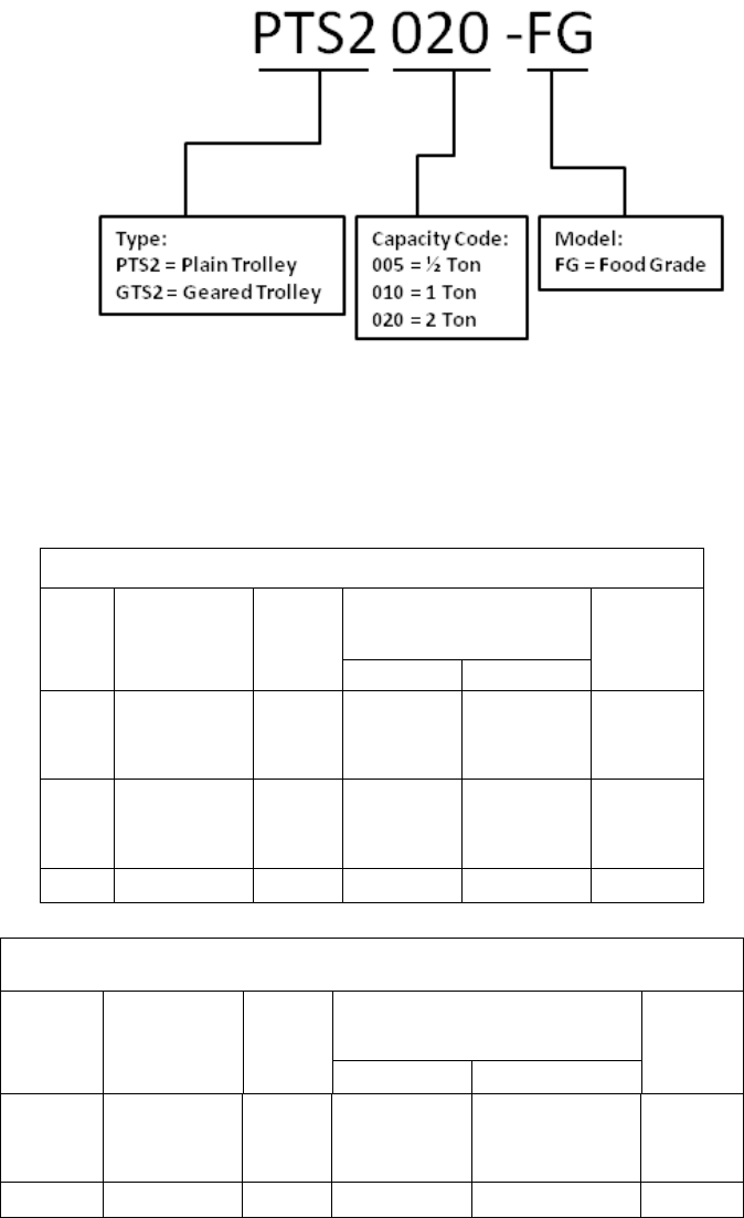
2.1 Specifications
Product Code for TS2 Trolley Alone:
Operating Conditions and Environment
Temperature Range:
-4° to +104°F (-20° to +40°C)
Humidity:
85% or less
Table 2-1 PTS2 Trolley Specifications
Cap.
(Tons) Product Code
Min.
Radius
for
Curve
(in)
Flange Width Adjustability
B
(in)
Approx. Net
Weight
(lbs)
Standard Option
1/2 PTS2005-FG 43.3 2.28 to 4.00
4.01 to 8.00
or
8.01 to 12.00
10
1 PTS2010-FG 51.2 2.28 to 5.00
5.01 to 8.00
or
8.01 to 12.00
18
2 PTS2020-FG 59.1 3.23 to 6.02 6.03 to 12.00 31
Table 2-2 GTS2 Trolley Specifications
Cap.
(Tons) Product Code
Min.
Radius
for
Curve
(in)
Flange Width Adjustability
B
(in)
Approx.
Net
Weight
(lbs)
Standard Option
1 GTS2010-FG 51.2 2.28 to 5.00
5.01 to 8.00
or
8.01 to 12.00
27
2 GTS2020-FG 59.1 3.23 to 6.02 6.03 to 12.00 42
18
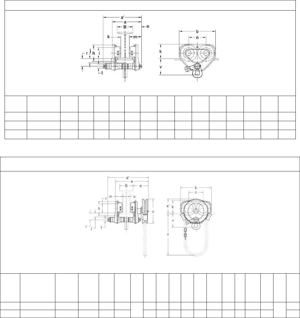
2.2 Dimensions
Table 2-3 PTS2 Trolley Dimensions
PTS2005 to PTS2020
Cap.
(Tons) Product
Code
a
max
(in)
a'
(in) b
(in) e
(ft) h
(in) i
(in) j
(in) k
(in) m
(in) n
(in) r
(in) s
(in) t
(in) v
(in)
1/2 PTS2005-FG 6.8 8.0 7.2 1.8 3.2 2.36 0.7 3.0 2.7 3.3 1.5 B-1.8 0.87 3.7
1 PTS2010-FG 8.5 9.8 9.3 2.2 4.2 2.80 1.1 3.7 3.1 4.4 2.0 B-1.9 0.98 4.2
2 PTS2020-FG 10.4 11.8 11.0 2.7 5.0 3.35 1.3 4.4 3.8 5.2 2.4 B-2.3 1.26 5.1
Table 2-4 GTS2 Trolley Dimensions
GTS2010 to GTS2020
Cap.
(Tons) Product Code a
max*
(in)
a’
max
(in)
b
(in) e
(in) f
(ft.) h
(in) i
(in) j
(in) k
(in) k'
(in) m
(in) n
(in) r
(in) s
(in) t
(in) u
(in) v
(in)
1/2-1 GTS2010-FG 10.8 13.6 9.3 6.0 10.5 4.2 2.80 1.1 3.7 4.2 2.2 4.4 2.0 B-1.8 0.98 7.2 4.2
2 GTS2020-FG 13.7 15.2 11.0 6.1 5.0 3.35 1.3 4.4 4.3 2.8 5.2 2.4 B-1.9 1.26 5.1
19
6.1 Lubrication
6.1.1 Lubricate the following trolley components with only Nevastane HT/AW 2 White Drum food grade
lubricating grease.
6.1.2 Track Wheel Gear – Clean and re-grease the Track Wheel gears and Hand Wheel output pinion every
three months (more frequently for heavier use). Do not use an excessive amount of grease and avoid
getting any grease on the running surfaces of the Track Wheels or the beam.
6.1.3 Trolley Wheel Bearings do not need to be lubricated and must be replaced if worn or damaged.
6.1.4 Suspension Pins, Bolts, and Shafts – Grease at least twice per year for normal usage (more frequently
for heavier usage or severe conditions).

20
This Page Intentionally Left Blank
21
V Parts List
1.0 NER2 Parts List
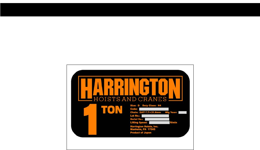
When ordering parts, please provide the hoist code number, lot number and serial number located on the hoist
nameplate (see fig. below).
Reminder: To aid in ordering parts and product support, record the hoist code number, lot number and serial
number in the space provided on the cover of this manual.
NER2 Series Nameplate
The parts list is arranged into the following sections:
Section Page
1.1 Housing and Motor Parts…………..…………….……………………………………………........ 22
1.2 Gearing Parts…………………………………………………………………………..................... 26
1.3 Hook and Chain Parts………………………………………………………………….…………... 30
1.4 Electric Parts (Single Speed)……………………………………………………………….……... 36
1.5 Electric Parts (Dual Speed)…………………………………………………………….………..... 38
1.6 Power Supply and Pendant Parts……………………………………...…………………………. 40
In the column "Parts Per Hoist" a designator is used for parts that apply only to a particular model or option.
Refer to Chapter 2, Section 2 for hoist model numbers and additional descriptions. The designators are:
S = Single Speed
D = Dual Speed
2V = 208/230 Volt Models
4V = 460 Volt Models
22
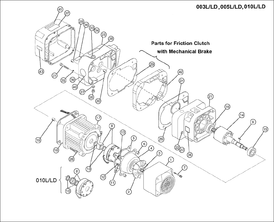
1.1 Housing and Motor Parts
Figure 1-1 Housing and Motor Parts

23
1.1 Housing and Motor Parts
Figure
No.
Part Name
Parts Per
Hoist
003L/LD 005L/LD 010L/LD
1
Fan Cover
1
2AFG005L9107
2AFG010L9107
2
Fan
1
ER2CL9108
ER2CS9108
3
Snap Ring
1
9047113
9047113
4 Brake Cover 1 ER2CL9115 ER2CS9115
5
Packing B
1
ER2CL9119
ER2CS9119
6
Set Pin S
2
ES120003
7
Socket Bolt
4
J1BEE0504522
8 Electromagnetic Brake
Assembly 1 MBABB0ENA MBABB09NA
9
Key B
1
ER2CL9360
ER2CS9360
10
Snap Ring
2
9047116
9047124
11
Socket Bolt
3
9091254
12
Spring Lock Washer
3
J1WB07420080
J1WB07420100
13
V Ring
1
ER2CS9210
ER2CS9210
14
Motor Shaft With Rotor
1
ER2CL5502
ER2DL5502
15
Ball Bearing
1
9000904
9000905
16
Ball Bearing
1
9000904
9000922
17 Motor Frame With
Stator
1 3AFG005L5501 3AFG010L5501
18
Packing M
1
ER2CS9118
ER2DS9118
19
Set Pin S
2
ES120010S
ER1DS9138
20
Socket Bolt
4
J1BEE0803535
J1BEE1003535
21 Body B Assembly 1 3AFG005S6101 3AFG010S6101
22
Oil Plug
1
E3S111003
23
Plug Packing
1
E3S112003
24
Snap Ring
1
9047262
9047268
25 Gear Case 1 3AFG005S6103 3AFG010S6103
26
Oil Plug
1
E3S111003
27
Plug Packing
1
E3S112003
28
Spring Pin
1
E3S129005S
29 Packing G 1 ER2CS9116 ER2DS9116
30 Set Pin S 2 ES120003
31 Socket Bolt 4 9091262
32
Toothed Lock Washer
4
9679709
33 Oil Fill Plug 1 ER1BS9135
34
Eyebolt Packing
1
ES127005S
35
Name Plate
Load Side E 1 ER1BS9960
36
Oil Full Tag
1
ER1BS9953
37
Warning Sticker E
(Disconnect Power)
1 ER2CS9936
38
Name Plate OF (Correct
Oil Required) 1 2AFG003S9845
40 Name Plate AD (Speed
Letter) 1 ER1BL9868 ER1BL9868
41
Warning Sticker HW
(Hot Surface) D 1 ER2CI9806
43 Check Voltage Label
S,2
V
1
ECP99NVVB
S,4
V
ECP99NVVA
D,2
V
ECP99NVWB
D,4
V
ECP99NVWA
24
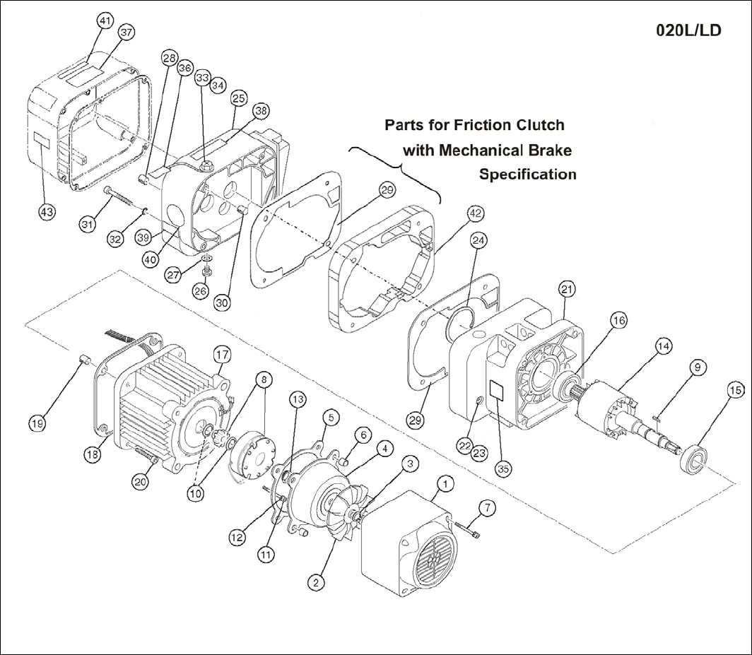
1.1 Housing and Motor Parts
Figure 1-2 Housing and Motor Parts

25
1.1 Housing and Motor Parts
Figure
No.
Part Name
Parts Per
Hoist
020L/LD
1
Fan Cover
1
2AFG020L9107
2
Fan
1
ER2DS9108
3
Snap Ring
1
9047116
4
Brake Cover
1
ER2DS9115
5
Packing B
1
ER2DS9119
6
Set Pin S
2
ES120003
7
Socket Bolt
4
J1BEE0504522
8
Electromagnetic Brake
Assembly 1 MBABB18NA
9
Key B
1
ER2DS9360
10 Snap Ring 2 9047124
11
Socket Bolt
3
9091254
12
Spring Lock Washer
3
J1WB07420120
13
V Ring
1
ER2DS9210
14
Motor Shaft With Rotor
1
ER2EL5502
15
Ball Bearing
1
9000905
16
Ball Bearing
1
9000906
17
Motor Frame With
Stator 1 3AFG020L5501
18
Packing M
1
ER2ES9118
19
Set Pin S
2
ER2ES9138
20
Socket Bolt
4
J1BEE1204040
21 Body B Assembly 1 3AFG020S6101
24
Snap Ring
1
9047280
25 Gear Case 1 3AFG020L6103
26
Oil Plug
1
E3S111003
27
Plug Packing
1
E3S112003
28
Spring Pin
1
E3S129005S
29 Packing G 1 ER2ES9116
30 Set Pin S 2 ES120010S
31 Socket Bolt 4 9091286
32 Toothed Lock Washer 4 9679711
33
Oil Fill Plug
1
ER1BS9135
34
Eyebolt Packing
1
ES127005S
35
Name Plate Load Side E
1
ER1BS9960
36 Oil Full Tag 1 ER1BS9953
37
Warning Sticker E
(Disconnect Power)
1 ER2CS9936
38 Name Plate OF (Correct
Oil Required) 1 2AFG003S9845
40
Name Plate AD (Speed
Letter)
1 ER1BL9868
41
Warning Sticker HW
(Hot Surface) D 1 ER2CI9806
43 Check Voltage Label
S,2V
1
ECP99NVVB
S,4V ECP99NVVA
D,2V ECP99NVWB
D,4V
ECP99NVWA

26
1.2 Gearing Parts
Figure 2-1 Gearing Parts

27
1.2 Gearing Parts
Figure
No. Part Name
Parts
Per
Hoist
003L/LD 005L/LD 010L/LD
1
Load Sheave
Assembly 1 ER2CS6241 ER2DS6241
2 Load Sheave 1 ER2DS9241 ER2DS9241
3
Oil Seal
1
ES221010S
ES221010S
4
Ball Bearing
1
9000508
5 Ball Bearing 1 9000302 9000304
6 Load Gear 1 ER2CL9240 ER2DS9240
7
Snap Ring
1
9047135
8
Ball Bearing
1
9000107
9
Oil Seal
1
ES232005S
10 Ball Bearing 1 9000201
11
Oil Seal
1
E6F235003S
12 Pinion Assembly 1 ER2CS5220 ER2DS5220
13 Socket Bolt 3 90912149
14 Friction Clutch
Complete
Assembly 1 ER2CL1223 ER2DL1223
15 Wave Washer 1 E1DBX20S9311
16 Nut Cover 1 ER1CS9235
17
Name Plate FP
(Adjustment Of
Friction Clutch
Prohibited)
1 ER1BS9892
18 Gear B Assembly 1 ER2DL5262
19 Gear Holder
Plate Assembly 1 ER2DL6261
20 Gear Holder
Plate 1 ER2DL9261
21 Ball Bearing 1 9000101
22 Ball Bearing 1 9000100
23 Set Pin S 2 ES120003
24 Socket Bolt 3 9091252
25 Spring Lock
Washer 3 9012709
28
1.2 Gearing Parts
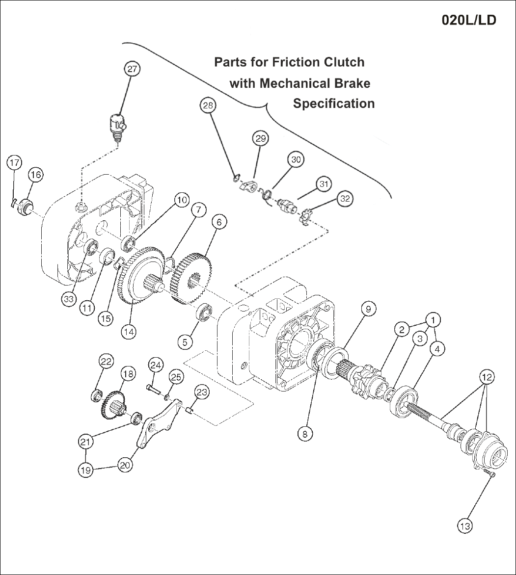
Figure 2-2 Gearing Parts

29
1.2 Gearing Parts
Figure
No. Part Name Parts
Per
Hoist 020L/LD
1 Load Sheave
Assembly
1 ER2ES6241
2
Load Sheave
1
ER2ES9241
3
Oil Seal
1
ER2ES9221
4
Ball Bearing
1
9000609
5 Ball Bearing 1 9000405
6 Load Gear 1 ER2EL9240
7
Snap Ring
1
9047150
8
Ball Bearing
1
9000110
9
Oil Seal
1
ER2ES9244
10
Ball Bearing
1
9000303
11
Oil Seal 22
1
ER1DS9233
12 Pinion Assembly 1 ER2EL5220
13
Socket Bolt
3
90912149
14
Friction Clutch
Complete
Assembly
1 ER2EL1223
15
Wave Washer
1
ER1DS9234
16
Nut Cover
1
ER1DS9235
17
Name Plate FP
(Adjustment Of
Friction Clutch
Prohibited)
1 ER1BS9892
18 Gear B Assembly 1 ER2EL5262
19 Gear Holder
Plate Assembly 1 ER2EL6261
20 Gear Holder
Plate 1 ER2EL9261
21 Ball Bearing 1 9000202
22 Ball Bearing 1 9000201
23 Set Pin S 2 ES120010S
24 Socket Bolt 3 9091275
25 Spring Lock
Washer 3 9012711
30
1.3 Hook and Chain Parts
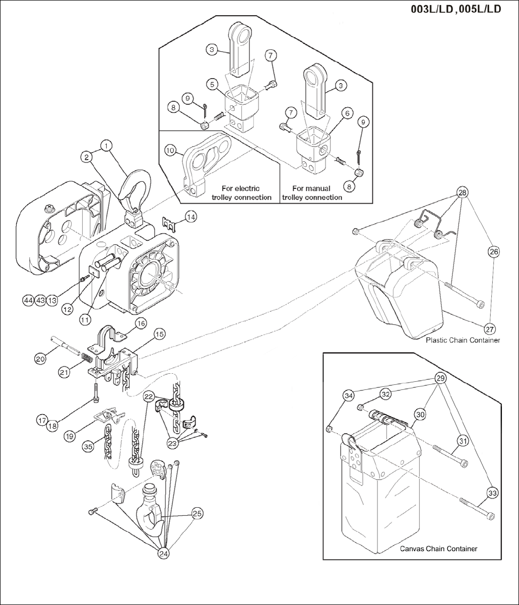
Figure 3-1 Hook and Chain Parts
*Optional stainless steel chain container assembly not shown. See Figure No. 45 on part number chart for ordering information.

31
1.3 Hook and Chain Parts
Figure
No. Part Name Parts
Per
Hoist 003L/LD 005L/LD
1
Top Hook Assembly
1
2ASF005S5101
2
Hook Latch
1
2ASF005S1103
3
Suspender E (For Push Trolley) –
White Epoxy Paint
1
36FG0059004
Suspender E (For Push Trolley) –
Nickel Plated 37FG0059004
Suspender E (For Geared Trolley) –
White Epoxy Paint 36FG0109004
Suspender E (For Geared Trolley) –
Nickel Plated 37FG0109004
5
Connection Yoke P (For Push Trolley) –
White Epoxy Paint 1 2AFG005S9027
6 Connection Yoke G (For Geared Trolley) –
White Epoxy Paint 1 2AFG005S9029
7
Yoke Bolt
1
2AFG005S9032
8
Slotted Nut
1
J1NL00910100
9
Split Pin
1
J1PW06025018
10
Suspender T (For Motorized Trolley) –
White Epoxy Paint 1 2AFG010S9031
Suspender T (For Motorized Trolley) –
Nickel Plated 2AFG010S9831
11 Top Pin 2 WR2CS9121
12
Plate A
1
ER2CS9123
13
Socket Bolt
1
J1BEE0601414
14
Shaft Clip
1
ER2CS9186
15 Chain Guide A 1 ER2CS9331
16
Chain Guide B
1
ER2CS9332
17
Socket Bolt
4
J1BEE0602525
18
Spring Lock Washer
4
J1WS07420060
19 Limit Lever 1 ER2CS9337
20
Limit Lever Pin
1
ER2CS9338
21
Limit Lever Spring
1
WR2CS9357
22
Cushion Rubber – Standard
2
ER1CS9053
Cushion Rubber – Stainless Steel 2 27SF005S9117
23
Stopper Assembly – Standard
1
ER1CS1041
Stopper Assembly – Nickel Plated
2AFG005S1041
24
Bottom Hook Complete Assembly –
White Epoxy Paint 1 2AFG005S1011
Bottom Hook Complete Assembly –
Stainless Steel
2ASF005S5211
25 Hook Latch 1 2ASF005S1103
26 Plastic Chain Container Assembly
(Max. Lifting Height 20ft) 1 PBK2-C-FG
27
Plastic Chain Container
1
ER2CS1401
28
Plastic Container Spring Assembly
1
2AFG005S1416
29 Canvas Chain Container Assembly
(Max. Lift Height 50ft) 1 BK2C2-FG
30 Canvas Chain Container 1 ER2CS5405
31
Socket Bolt
1
J1BEB0807528
32
Lever Nut
1
J1NU00920080
33
Socket Bolt
1
J1BEB0604508
34
Lever Nut
1
J1NU00920080
35
NP Load Chain
1
LCER2005NP-FG
35
ND Load Chain
1
LCER2005ND-FG
43 Washer 1 J1WB07420060
44
Spring Lock Washer
1
J1WS07420060
45
Stainless Steel Chain Container Assembly
– maximum 23 ft. lift
1
7042201
Stainless Steel Chain Container Assembly
– maximum 49 ft. lift 7042202
32
1.3 Hook and Chain Parts
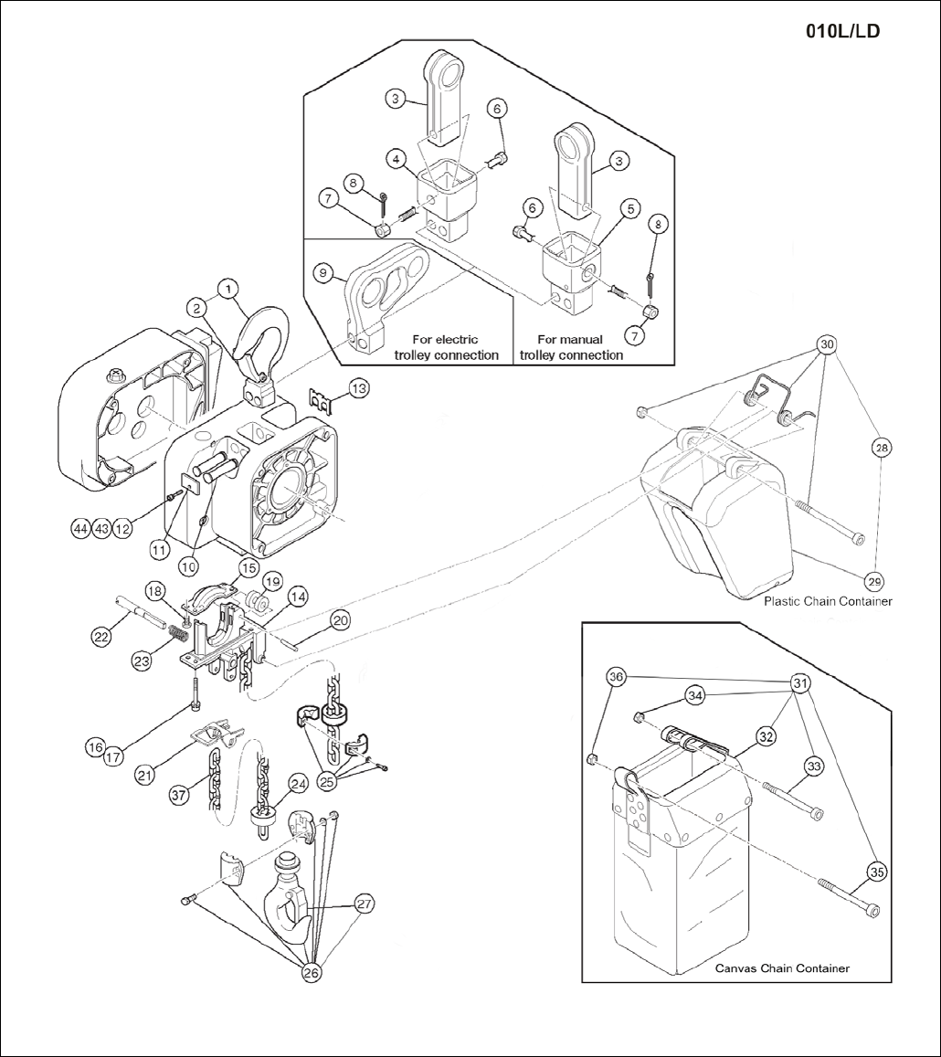
Figure 3-2 Hook and Chain Parts
*Optional stainless steel chain container assembly not shown. See Figure No. 45 on part number chart for ordering information.

33
1.3 Hook and Chain Parts
Figure
No. Part Name Parts
Per
Hoist 010L
1 Top Hook Assembly 1 2ASF010S5101
2
Hook Latch
1
2ASF010S1103
3
Suspender E (For Manual Trolley) –
White Epoxy Paint
1 36FG0109004
Suspender E (For Manual Trolley) –
Nickel Plated
37FG0109004
4
Connection Yoke P (For Push Trolley) –
White Epoxy Paint
1 2AFG005S9027
5
Connection Yoke G (For Geared Trolley) –
White Epoxy Paint
1 2AFG005S9029
6
Yoke Bolt
1
2AFG005S9032
7
Slotted Nut
1
J1NL00910100
8 Split Pin 1 J1PW06025018
9
Suspender T (For Motorized Trolley) –
White Epoxy Paint 1 2AFG010S9031
Suspender T (For Motorized Trolley) –
Nickel Plated 2AFG010S9831
10
Top Pin
2
WR2CS9121
11
Plate A
1
ER2CS9123
12 Socket Bolt 1 J1BEE0601414
13
Shaft Clip
1
ER2CS9186
14
Chain Guide A
1
ER2DS9331
15
Chain Guide B
1
ER2DS9332
16 Socket Bolt 4 J1BEE0802525
17
Spring Lock Washer
4
J1WS07420080
18
Machine Screw With Spring Washer
4
J1AP45001212
19
Guide Roller
1
ER2DS9333
20 Roller Pin 1 ER1CS9334
21
Limit Lever
1
ER2DS9337
22
Limit Lever Pin
1
ER2DS9338
23
Limit Lever Spring
1
WR2CS9357
24 Cushion Rubber – Standard 2 ER1DS9053
Cushion Rubber – Stainless Steel
2
27SF010S9117
25
Stopper Assembly – Standard
1
ER1DS1041
Stopper Assembly – Nickel Plated
2AFG010S1041
26
Bottom Hook Complete Assembly –
White Epoxy Paint 1 2AFG010S1011
Bottom Hook Complete Assembly –
Stainless Steel 2ASF010S5211
27 Hook Latch 1 2ASF010S1103
28
Plastic Chain Container Assembly
(Max. Lifting Height 20ft) 1 PBK2-D-FG
29
Plastic Chain Container
1
ER2DS1401
30
Plastic Container Spring Assembly
1
2AFG010S1416
31
Canvas Chain Container Assembly
(Max. Lifting Height 50ft)
1 BK2D2-FG
32
Canvas Chain Container
1
ER2DS5405
33
Socket Bolt
1
J1BEB0809028
34
Lever Nut
1
J1NU00920080
35
Socket Bolt
1
J1BEB0604508
36 Lever Nut 1 J1NU00920060
37 NP Load Chain 1 LCER2010NP-FG
37
ND Load Chain
1
LCER2010ND-FG
43
Washer
1
J1WB07420060
44
Spring Lock Washer
1
J1WS07420060
45
Stainless Steel Chain Container Assembly –
maximum 26 ft. lift 1 7042203
Stainless Steel Chain Container Assembly –
maximum 49 ft. lift 7042205
34
1.3 Hook and Chain Parts
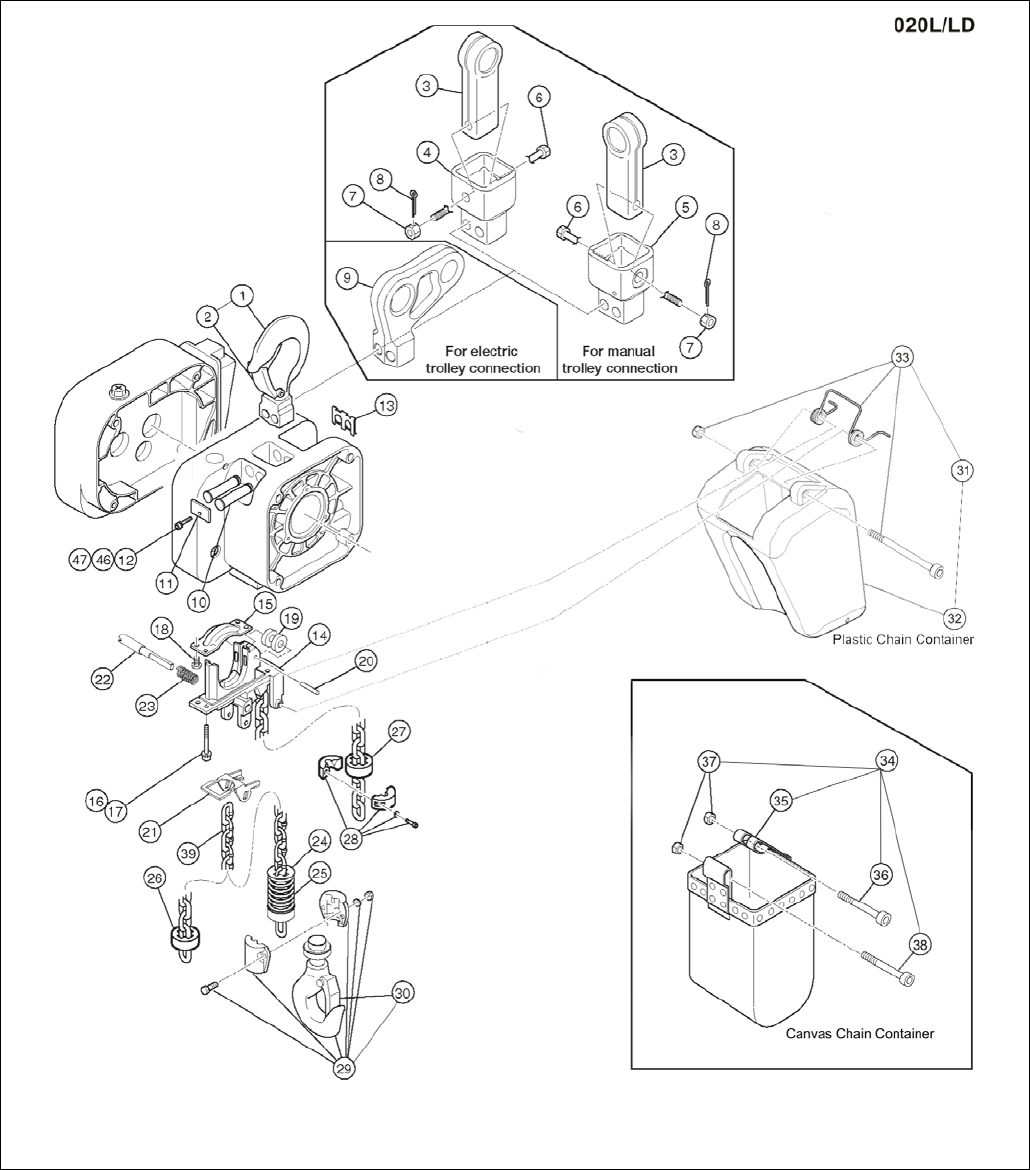
Figure 3-3 Hook and Chain Parts
*Optional stainless steel chain container assembly not shown. See Figure No. 45 on part number chart for ordering information.

35
1.3 Hook and Chain Parts
Figure
No. Part Name Parts
Per
Hoist 020L
1
Top Hook Assembly
1
2ASF020S5101
2
Hook Latch
1
2ASF020S1103
3
Suspender E (For Manual Trolley) –
White Epoxy paint 1 36FG0209004
Suspender E (For Manual Trolley) –
Nickel Plated 37FG0209004
4 Connection Yoke P (For Push Trolley) –
White Epoxy Paint 1 2AFG020S9027
5 Connection Yoke G (For Geared Trolley) –
White Epoxy Paint 1 2AFG020S9029
6 Yoke Bolt 1 2AFG020S9032
7
Slotted Nut
1
J1NL00920160
8
Split Pin
1
J1PW06040030
9
Suspender T (For Motorized Trolley) –
White Epoxy Paint
1 2AFG020S9031
Suspender T (For Motorized Trolley) –
Nickel Plated
2AFG020S9831
10
Top Pin
2
2AFG020S9121
11 Plate A 1 ER2ES9123
12
Socket Bolt
1
J1BEE0601414
13
Shaft Clip
1
ER2ES9186
14
Chain Guide A
1
ER2ES9331
15 Chain Guide B 1 ER2ES9332
16
Socket Bolt
4
J1BEE0803030
17
Spring Lock Washer
4
J1WS07420080
18 Machine Screw With Spring Washer 4 J1AP46001212
19 Guide Roller 1 ER1DL9333
20
Roller Pin
1
ER1DL9334
21
Limit Lever
1
ER2ES9337
22
Limit Lever Pin
1
ER2EL9338
23
Limit Lever Spring
1
WR2CS9357
24
Limiting Plate – Standard
1
ER1ES9054
Limiting Plate – Stainless Steel
27SF020S9118
25 Chain Spring – Standard 1 ER1DL9051
Chain Spring – Stainless Steel
2AFG020L9112
27
Cushion Rubber – Standard
1
ER1ES9053
Cushion Rubber – Stainless Steel
27SF020S9117
28
Stopper Assembly – Standard
1
ER1ES1041
Stopper Assembly – Nickel Plated
2AFG020S1041
29
Bottom Hook Complete Assembly –
White Epoxy Paint
1 2AFG020S1011
Bottom Hook Complete Assembly –
Stainless Steel
2ASF020S5211
30
Hook Latch
1
2ASF020S1103
31
Plastic Chain Container Assembly
(Max. Lifting Height 13ft)
1 PBK2-E-FG
32
Plastic Chain Container
1
ER2ES1401
33 Plastic Container Spring Assembly 1 2AFG020S1416
34
Canvas Chain Container Assembly
(Max. Lifting Height 60ft) 1 BK2E2-FG
35
Canvas Chain Container
1
ER2ES5405
36
Socket Bolt
1
J1BEB1010032
37
Lever Nut
2
J1NU00920100
38 Socket Bolt 1 J1BEB1007532
39
NP Load Chain
1
LCER2020NP-FG
39
ND Load Chain
1
LCER2020ND-FG
45
Stainless Steel Chain Container Assembly –
maximum 20 ft. lift
1 7042204
Stainless Steel Chain Container Assembly –
maximum 39 ft. lift
7042206
46
Washer
1
J1WB07420060
47
Spring Lock Washer
1
J1WS07420060
36
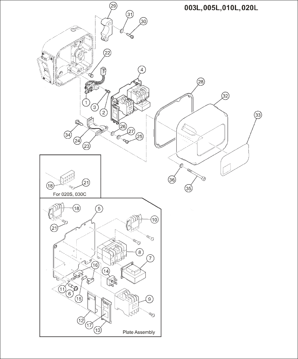
1.4 Electric Parts (Single Speed)
Figure 4-1 Electric Parts (Single Speed)
37
1.4 Electric Parts (Single Speed)
Figure
No. Part Name Parts
Per
Hoist 003L 005L 010L 020L
1
Limit Switch
Complete
Assembly
1 ER2CI1060
2
Socket Bolt
3
9091247
3
Spring Lock
Washer 3 9012709
4
Plate Assembly
1
ER2GHM05L5A2
ER2GHM10S5A2
ER2GHM20L5A2
5
Plate
1
ER2CS9441
ER2DS9441
ER2ES9441
6
Plate Screw
3
ER1BS9445
7
Transformer
1
TRF72V611
TRF73V611
8
Electromagnetic
Contactor 1 MGC23406C
9 E-Stop
Contactor 1 MGC13306F**
MGC14306C**
10
Terminal Block
3P
1 ECP1303AB ECP1303AB
Terminal Block
9P ECP1309AB
11
Lead Wire
1
ER2GHM05L9A2
ER2GHM05S9A2
ER2GHM20S9A2
12
CH Meter
1
ECP91CHAE
13
CH Meter
Support 1 ECP99BKBA
14 Rectifier 1 ECP93DIAA ECP94DIAA
15
Fuse
1
9006275
16
Fuse Holder
1
ECP92FZAA
17
Name Plate CH
1
ECP99CHAA
18
Terminal Block
6P
1 ECP1306AD ECP1306AD
22
Fulcrum Pin
1
ER2CS9449
23 Cover
Suspender
1 ER2CS9456
24
Cover Belt
1
ER2CS9457
25
Socket Bolt
1
9091249
26
Plain Washer
1
ER1BS9436
27
Spring Lock
Washer 1 9012709
28
Packing C
1
ER2CS9117
ER2DS9117
ER2ES9117
32 Controller Cover F 1 2AFG005S9104 2AFG010S9104 2AFG020S9104
33
Name Plate B
1
ER2BHM05S9A5
ER2BHM10S9A5
ER2BHM20S9A5
34
Pan Head Mach.
Screw 2 9798534
35 Socket Bolt 4 J1BEE0504022 J1BEE0604024
36 Washer 1 J1WB07420050 J1WB07420060
**Refer to the alpha-numeric code on contactor. The code “S-U12” corresponds to MGD13306F.
The code “S-N11” corresponds to MGC13306H. The code “CLK-25J3” corresponds to MGC14306C.
38
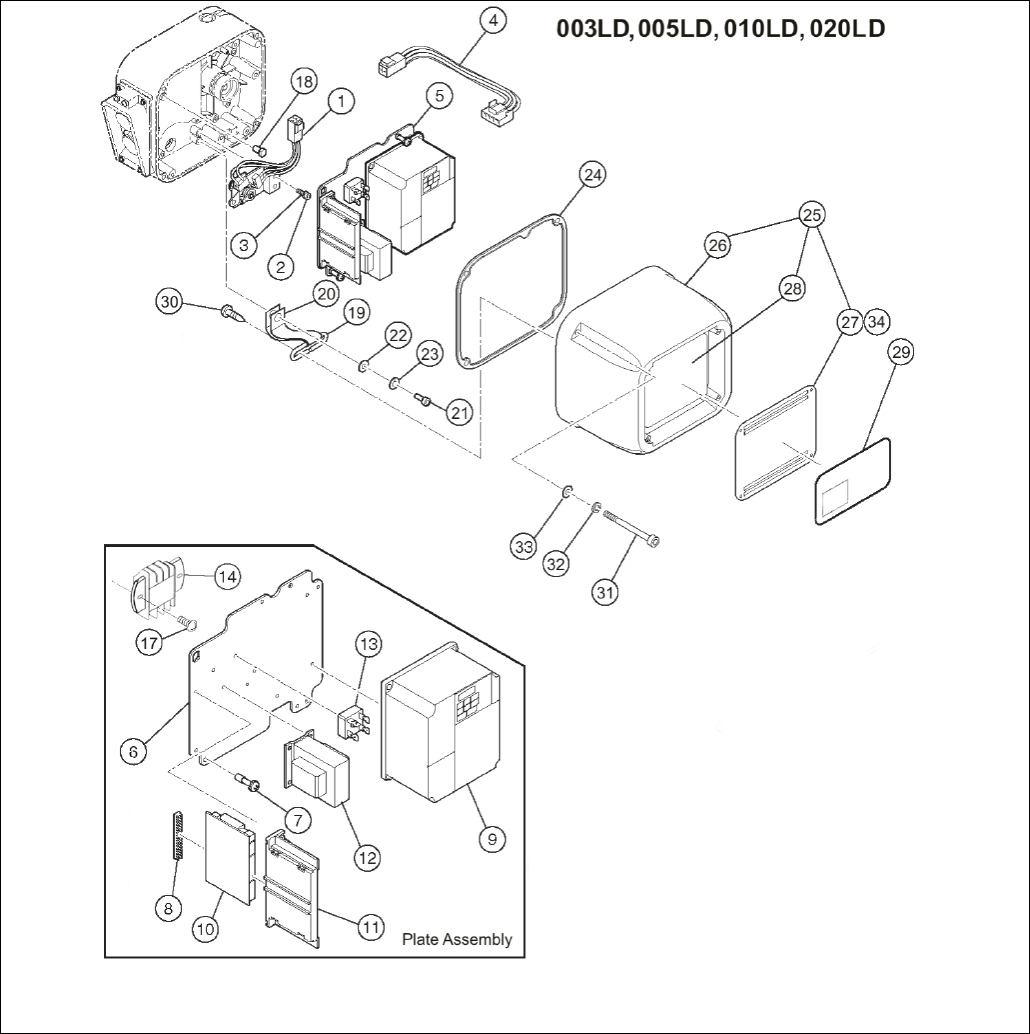
1.5 Electric Parts (Dual Speed)
Figure 5-1 Electric Parts (Dual Speed)

39
1.5 Electric Parts (Dual Speed)
Figure
No. Part Name Parts Per
Hoist 005LD 010LD 020LD
1
Limit Switch
Complete
Assembly 1 ER2CI1060
2
Socket Bolt
3
9091247
3
Spring Lock
Washer
3 9012709
4
LS Harness
1
ER2CI9554
5 Plate Assembly
M, 2V 1 ER2LHE05J5A2 ER2LHE10J5A2 ER2LHE20J5A2
F, 2V 1 ER2BHE05J5A2 ER2BHE10J5A2 ER2BHE20J5A2
M, 4V 1 ER2LHN05J5A2 ER2LHN10J5A2 ER2LHN20J5A2
F, 4V 1 ER2BHN05J5A2 ER2BHN10J5A2 ER2BHN20J5A2
6
Plate
1
ER2CI9441
ER2DI9441
ER2EI9441
7
Plate Screw
3
ER1BS9445
8
Bushing
1
ECP99JBAC
9 Inverter Assembly
M, 2V
1
INV60FH24
INV615H24
INV622H24
F, 2V
INV60FH21
INV615H21
INV622H21
M, 4V
INV60FM24
INV615M24
INV622M24
F, 4V INV60FM21 INV615M21 INV622M21
10 Interface Board 1 ECP91KB02
11 Board Support 1 ECP99BKAA
12 Transformer 2V 1 TRF32C612
4V TRF32N612
13 Rectifier 1 ECP93DIAA
14
Terminal Block 6P
1
ECP1306AD
17
Machine Screw
2
9798512
18
Fulcrum Pin
1
ER2CS9449
19
Cover Suspender
1
ER2CS9456
20
Cover Belt
1
ER2CS9457
21
Socket Bolt
1
9091249
22
Plain Washer
1
ER1BS9436
23
Spring Lock
Washer 1 9012709
24
Packing C
1
ER2CS9117
ER2DS9117
ER2ES9117
25 Controller Cover
Assembly
2V
1
2AFG005I2104
2AFG010I2104
2AFG020I2104
4V
2AFG005I1104
2AFG010I1104
2AFG020I1104
26
Controller Cover
1
2AFG005I9104
2AFG010I9104
2AFG020I9104
27
Resistor Cover
1
2AFG005I9185
2AFG010I9185
2AFG020I9185
28 Braking Resistor
2V
1
INV70EE16
INV718E16
INV718E16
4V
INV70EY16
INV718Y16
INV718Y16
34
Mach. Screw
w/Spring Washer 4 JAW44001212
29 Name Plate B 1 ER2BHM05I9A5 ER2BHM10I9A5 ER2BHM20I9A5
30
Pan Head
Machine Screw
2 9798534
31
Socket Bolt
4
J1BEE0504022
J1BEE0604024
32
Toothed Lock
Washer
4 J1WS07420050 J1WS07420060
33
Washer
4
J1WB07420050
J1WB07420060
40
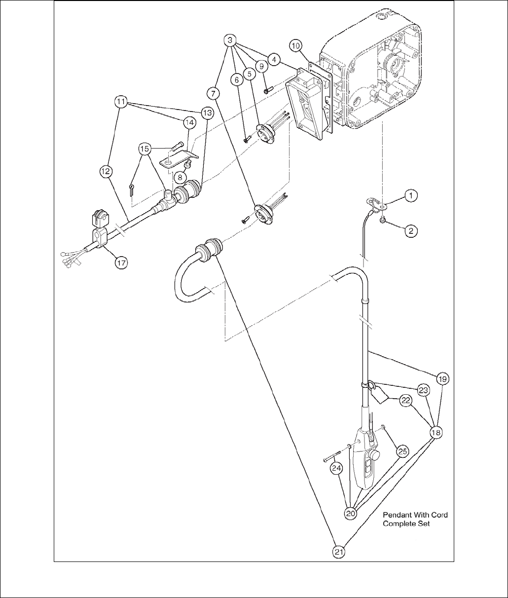
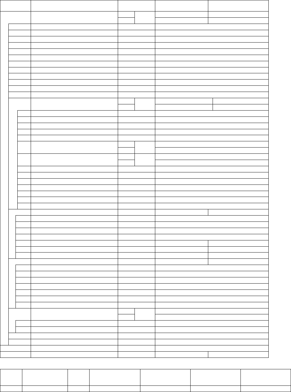
1.6 Power Supply and Pendant Parts
Figure 6-1 Power Supply and Pendant Parts (Plug Connection)

41
1.6 Power Supply and Pendant Parts
Figure
No. Part Name Parts
Per
Hoist 005L/LD 010L/LD 020L/LD
1
Cord Support
(Wire Stop)
1 ER1BS9534
2
Mach. Screw
W/Spring
Washer 2 J1AP45001212
3 Socket Frame
Complete
Assembly
S 1 2AFG005S4511 2AFG020S4511
D 2AFG005I4511 2AFG010I4511 2AFG020I4511
4
Socket Frame
1
2AFG005S9511
5 Socket 4P
Assembly
S
1
ER2CS2523
ER2ES2523
D
ER2CI2523
ER2CS2523
ER2EI2523
6
Tapping Flat
Head Mach.
Screw
8 ES558003
7 Socket 8P
Assembly
S
1
ER2CS2564
D
ER2CI2564
ER2EI2564
8
Mach. Screw
W/Spring
Washer
2 ES650005S
9
Mach. Screw
W/ Spring
Washer 6 J1AP45002020
10
Socket Frame
Packing
1 ER2CS9512
11
Power Supply
Cable 4C
Assembly
1 ZBZA12CH1000
12
Power Supply
Cable 4C ft 16/4
13
Plug 4P
1
ECP2304AD
14
Cable
Support Arm
1 ER1BS9541
15
Cable
Support 12
Assembly 1 ES822003
17 Cable Hanger
14 Assembly
A/R ES1527003
18
Pendant
W/Cord
Complete
Assembly
S 1 ZB10025H1000
D ZB20025I1000
19 Pendant Cord
S
ft
16/4P
D
16/6P
20 Pendent
Assembly
S
1
SWD1100AAH
D
SWD2200AAH
21 Plug 8P
S
1
ECP2108AA
D
ECP2108AB
22
Warning Tag
PB 1 WTAG7
23
Tag Holder
1
E3S787003
24
Machine
Screw 1 J1AP24002608
25
Nut
1
9093414
Note: A/R = As required, one every 5 ft. of Power Supply Cable.

42
This Page Intentionally Left Blank
43
2.0 MR2 Parts List
When ordering parts, please provide the trolley code number, lot number and serial number located on the hoist
nameplate (see fig. below).
Reminder: To aid in ordering parts and product support, record the trolley code number, lot number and serial
number in the space provided on the cover of this manual.
MR2 Series Name Plate
The parts list is arranged into the following sections:
Section 1/4 to 2 Ton Page
2.1 Electric Parts – 1/4 to 2 Ton………………………….………………………………...………….. 44
2.2 Pendant Parts – 1/4 to 2 Ton ……………………………………………………………………… 48
2.3 Power Supply Parts – 1/4 to 2 Ton ……………………………………………………….………. 50
2.4 Side Plates and Suspension Parts – 1/4 to 2 Ton ………………………………………..…….. 52
2.5 Motor Parts – 1/4 to 2 Ton ………………………………………….………………….………….. 54
In the column "Parts Per Trolley" a designator is used for parts that apply only to a particular model or option.
Refer to Chapter 3, Section 2 for MR2 trolley model numbers and additional descriptions.
The designators are:
S = Single Speed
W = SS/SS = Single Speed Hoist, Single Speed Trolley
D = Dual Speed
X = SS/DS = Single Speed Hoist, Dual Speed Trolley
PC = Plug Connection
Y = DS/SS = Dual Speed Hoist, Single Speed Trolley
2V = 208/230 Volt Models
Z = DS/DS = Dual Speed Hoist, Dual Speed Trolley
4V = 460 Volt Models
44
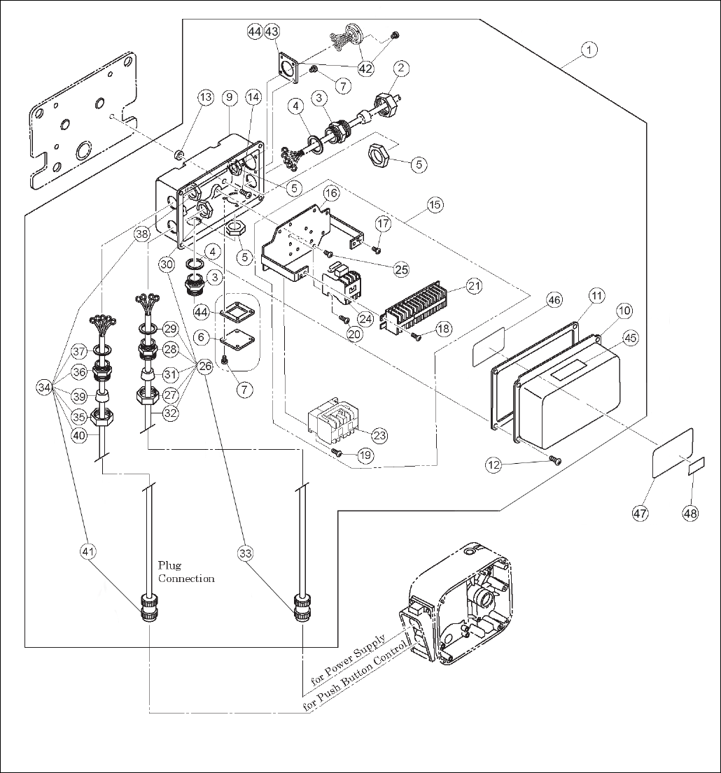
2.1 Electric Parts – 1/4 to 2 Ton (Single Speed)
Figure 1-1 Electric Parts (Single Speed)
45
2.1 Electric Parts– 1/4 to 2 Ton (Single Speed)
Figure No. Part Name Parts
Per
Trolley 1 Ton 2 Ton
1
Connection Box Assembly
1
7038101
7038102
2
Holder A
1
ECP5924AA
3 Holder B 2 ECP5924AB
4 Packing 2 ECP5924AC
5
Holder Nut
2
ECP5924AD
6
Cord Cover
1
E6F630010S
7 Machine Screw With Spring Washer 8 J1AP45001010
9 Connection Box 1 3AFG010S9401
10 Connection Box Cover 1 3AFG010S9411
11
Connection Box Packing
1
MR1DS9421
12 Machine Screw With Spring Washer 4 J1AP45001010
13
Spacer
4
MS517010
14 Machine Screw With Spring Washer 4 J1AP48002020
15
Complete Plate Assembly
1
MR2RHM10M1A5
16
Plate
1
MR2DS5445
17 Machine Screw With Spring Washer 3 MS555010
18 Machine Screw With Spring Washer 2 MS556010
19 Machine Screw With Spring Washer 2 MS556010
20 Machine Screw With Spring Washer 2 MS556010
21
Terminal 16P
1
ECP1416AA
23
Electromagnetic Contactor
1
MGC22306B
24
E-Stop Contactor
1
MGC12306B
25
Machine Screw With Spring Washer
4
MS554010
26
Power Supply Cable Assembly
1
MR2DS1759
MR2ES1759
27
Holder A
1
ECP5924AA
28
Holder B
1
ECP5924AB
29
Packing
1
ECP5924AC
30
Holder Nut
1
ECP5924AD
31
Cable Packing
1
ECP6912AA
ECP6916AA
32
S.O. Cord 4C
1
16/4
14/4
33
Plug 4P
1
ECP2304AD
ECP2304AF
34
Control Cable Assembly
1
MR2DS1768
MR2ES1768
35
Holder A
1
ECP5924AA
36
Holder B
1
ECP5924AB
37
Packing
1
ECP5924AC
38
Holder Nut
1
ECP5924AD
39
Cable Packing
1
ECP6916AA
40 S.O. Cord 6C 1 16/6P
41 Plug 8P 1 ECP2108AC
42 Socket 8P Assembly 1 MR2DS2811
43 Plate P 1 ECP5924AH
44 Cord Cover Packing 2 MS527010
45 Warning Seal E (Electric Shock) 1 ER2CS9936
46
Wiring Diagram
1
EWG3110H01
47
Name Plate B
1
MR2SHM10S9A8
48
Name Plate C
1
MR2SHM10S9A7
MR2SHM20S9A7
Name Plates for 1/8, 1/4, 1/2 & 1 1/2 Ton Capacities
Figure
No. Part Name
Parts
Per
Trolley 1/8 Ton 1/4 Ton 1/2 Ton 1 1/2 Ton
48 Name Plate C 1 MR2SHM01S9A7 MR2SHM03S9A7 MR2SHM05S9A7 MR2SHM15S9A7
46
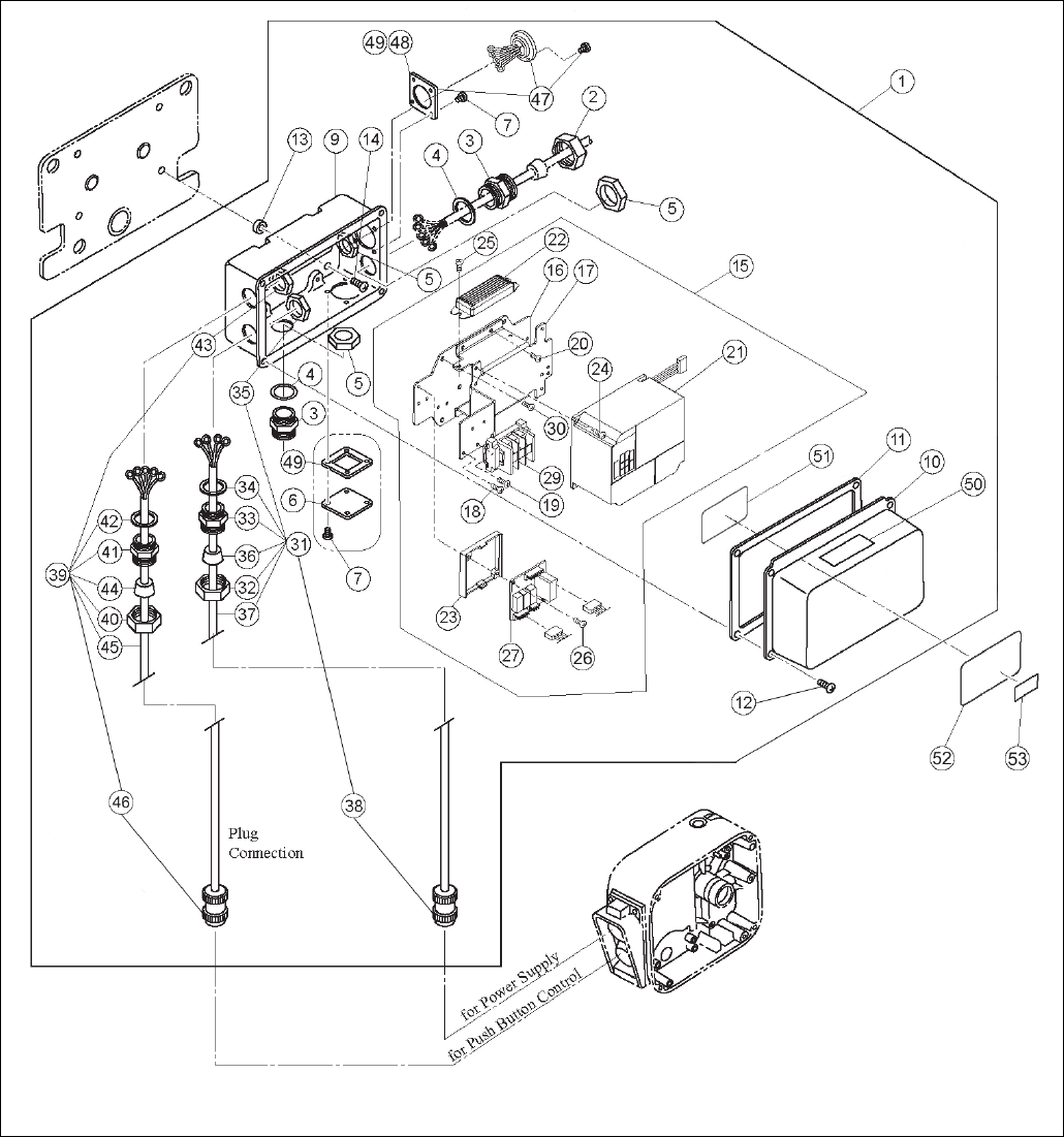
2.1 Electric Parts – 1/4 to 2 Ton (Dual Speed)
Figure 1-2 Electric Parts (Dual Speed)
47
2.1 Electric Parts– 1/4 to 2 Ton (Dual Speed)
Figure No. Part Name
Parts Per
Trolley 1 Ton 2 Ton
1 Connection Box Assembly
2V
1
7038201
7038202
4V
7038203
7038204
2
Holder A
1
ECP5924AA
3
Holder B
2
ECP5924AB
4
Packing
2
ECP5924AC
5
Holder Nut
2
ECP5924AD
6
Cord Cover
1
E6F630010S
7
Machine Screw With Spring Washer
8
J1AP45001010
9
Connection Box
1
3AFG010S9401
10
Connection Box Cover
1
3AFG010S9411
11
Connection Box Packing
1
MR1DS9421
12
Machine Screw With Spring Washer
4
J1AP45001010
13
Spacer
4
MS517010
14
Machine Screw With Spring Washer
4
J1AP48002020
15 Complete Plate Assembly 2V 1 MR2IHE10R1A5 MR2IHE20RIA5
4V MR2IHN10R1A5 MR2IHN20R1A5
16 Plate 1 MR2DI9441
17 Plate B 1 MR2DI9443
18 Machine Screw With Spring Washer 3 MS555010
19 Machine Screw With Washers 2 J1AW24000808
20
Machine Screw With Spring Washer
4
MS555010
21 VFD Assembly
2V
1
INV604E31
4V
INV604N31
22 Braking Resistor
2V
1
INV904E34
4V
INV904Y34
23
Board Support
1
ECP99BKAB
24
Machine Screw With Spring Washer
2
MS555010
25
Machine Screw With Washers
2
J1AW24000808
26
Machine Screw With Spring Washer
2
MS556010
27
Interface Board
1
ECP91KB12
29
Terminal 3P
1
ECP1403AA
30
Machine Screw With Spring Washer
4
MS554010
31
Power Supply Cable Assembly
1
MR2DS1759
MR2ES1759
32
Holder A
1
ECP5924AA
33 Holder B 1 ECP5924AB
34 Packing 1 ECP5924AC
35 Holder Nut 1 ECP5924AD
36 Cable Packing 1 ECP6912AA ECP6916AA
37 S.O. Cord 4C 1 16/4 14/4
38
4P Plug
1
ECP2304AD
ECP2304AF
39
Control Cable Assembly
1
MR2DI1768
MR2EI1768
40
Holder A
1
ECP5924AA
41
Holder B
1
ECP5924AB
42
Packing
1
ECP5924AC
43
Holder Nut
1
ECP5924AD
44
Cable Packing
1
ECP6916AA
45
S.O. Cord 6C
1
16/6P
46
8P Plug
1
ECP2108AC
47 Socket 8P Assembly
2V
1
MR2DI1811
4V
MR2DI2811
48
Plate P
1
ECP5924AH
49
Cord Cover Packing
2
MS527010
50
Warning Seal E (Electric Shock)
1
ER2CS9936
51
Wiring Diagram
1
EWG3DD0H01
52
Name Plate B
1
MR2SHM10S9A8
53 Name Plate C 1 MR2SHM10S9A7 MR2SHM20S9A7
Name Plates for 1/8, 1/4, 1/2 & 1 1/2 Ton Capacities
Figure
No. Part Name
Parts
Per
Trolley
1/8 Ton 1/4 Ton 1/2 Ton 1 1/2 Ton
53
Name Plate C
1
MR2SHM01S9A7
MR2SHM03S9A7
MR2SHM05S9A7
MR2SHM15S9A7
48
2.2 Pendant Parts – 1/4 to 2 Ton
Figure 2-1 Pendant Parts
49
2.2 Pendant Parts – 1/4 to 2 Ton
Figure
No. Part Name Parts Per
Trolley 1 Ton 2 Ton
1 Push Button Cord 6C/7C/8C
Complete Assembly
W
1
ZB1102AI1000
X
ZB1202AI1000
Y
ZB2102AI1000
Z
ZB2202AI1000
4 Push Button Cord 6C W 1 16/6P
Push Button Cord 8C X, Y, Z 16/8P
5 Warning Tag PB 1 WTAG7
6 Tag Holder 1 E3S787003
7 Machine Screw With Spring
Washer
1 J1AP24002608
8
Nut
1
9093414
9 Plug 8P
W, PC
1
ECP2108AB
X, Y, Z,
PC
ECP2108AD
10 5 Push Button Switch
Assembly
W
1
SWD2110ABH
X
SWD2120ABH
Y
SWD2210ABH
Z
SWD2220ABH
11 Bar Holder Assembly 1 MR1DS1481
12
Bar Holder
1
MR1DS9481
13
Cord Strain Relief Stopper
1
E6L614010S
14 Machine Screw w/Spring
Washer 2 E6F151003
15 Socket Bolt 2 J1BEE1002828
16 Spring Washer 2 J1WS07420100
50
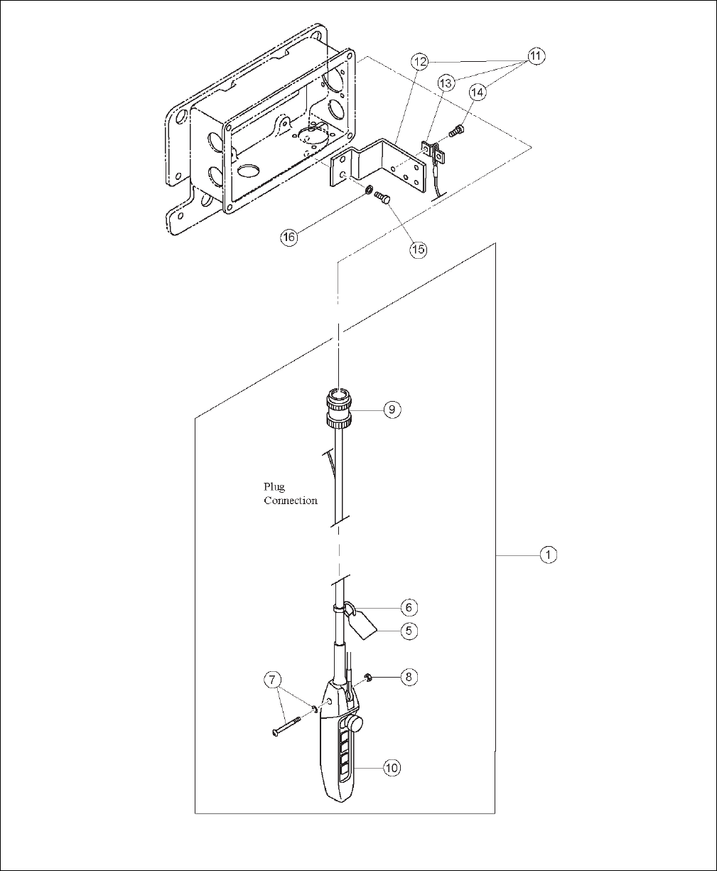
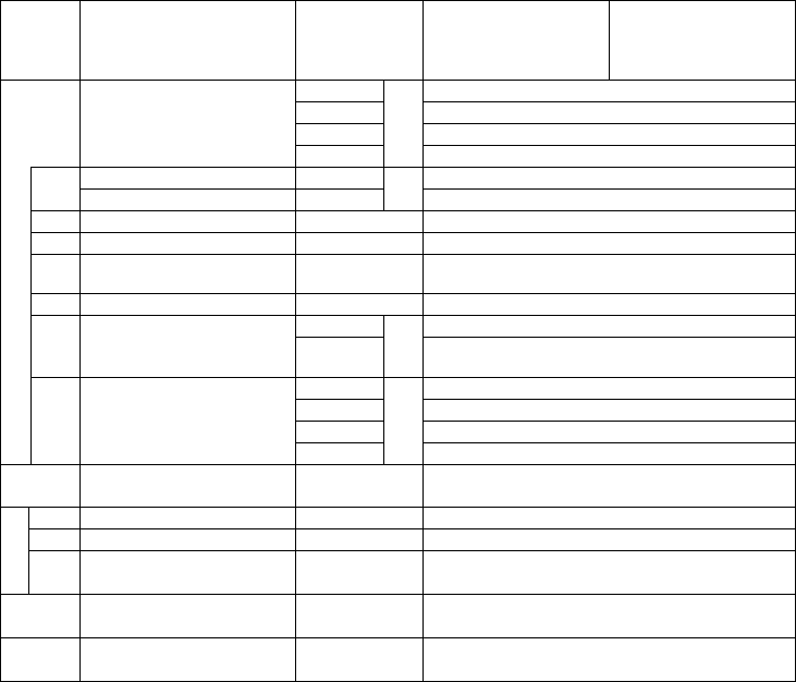
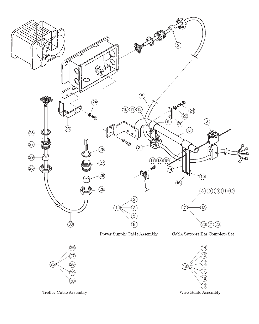
2.3 Power Supply Parts – 1/4 to 2 Ton
Figure 3-1 Power Supply Parts

51
2.3 Power Supply Parts – 1/4 to 2 Ton
Figure No. Part Name Parts
Per
Trolley 1 Ton 2 Ton
1
Power Supply Cable 4C Assembly
1
ZBZC12AH1100
ZBZC12BH1100
2
Cable Packing
1
ECP6914AA
ECP6916AA
3
Cable Support 14 Assembly
1
M3ES0101724
5 Power Supply Cable 4C 1 14/4 12/4
6 Cable Hanger 14 Assembly A/R ES1527003 MS1733020
7 Cable Support Bar Assembly 1 MR1DS1491
8 Cable Support Bar 1 MR1DS9491
9 Cable Support Arm 1 MR1DS9492
10
Bolt
1
9093328
11
Spring Lock Washer
1
9012711
12
Nut
1
9093424
13
Wire Guide Assembly
1
MR1DS1493
14
Wire Guide
1
MR1DS9493
15
Wire Stopper
1
MR1DS9496
16
Machine Screw With Spring Washer
2
M6F554010
17
Bolt
1
9093328
18
Spring Lock Washer
1
9012711
19
Nut
1
9093424
20
Support Bar Holder (Plate)
1
MR1DS9501
21
Bolt
2
9093329
22
Spring Lock Washer
2
9012711
23
Cable Hanger Pusher (Beam 75mm)
1
3AFG010S9511
Cable Hanger Pusher (Beam 100-
150mm) 1 3AFG010S9512
24 Socket Bolt With Spring Washer 2 J1BGE1002828
25 Trolley Cable 6C Assembly 1 MR2DS1793
26 Holder A 2 ECP5924AA
27 Holder B 2 ECP5924AB
28
Packing
2
ECP5924AC
29
Cable Packing
2
ECP6912AA
30
Trolley Cable 6C
1
16/6
*A/R = As Required, one for every 5 ft of power Supply Cable.

52
2.4 Side Plates and Suspension Parts – 1/4 to 2 Ton
Figure 4-1 Side Plates and Suspension Parts

53
2.4 Side Plates and Suspension Parts– 1/4 to 2 Ton
Figure
No. Part Name
Parts
Per
Trolley
1 Ton 2 Ton
2
Side Plate G Assembly – Standard Wheels
1
3AFG010S5201
3AFG020S5201
Side Plate G Assembly – Stainless Steel
Wheels
3AFG010S5801 3AFG020S5801
3
Track Wheel G Assembly – Standard
2
MS1101010
MS1101020
Track Wheel G Assembly – Stainless Steel
35MW0105101
35MW0205101
4
Washer
2
MS104010
MS104020
5
Snap Ring – Standard
2
9047115
9047120
Snap Ring – Stainless Steel
J1SS10000015
J1SS10000020
6
Side Roller Assembly – Standard
4
MR1DS1211
MR1ES1211
Side Roller Assembly – Stainless Steel
3AFG010S2211
3AFG020S2211
8 Bolt 4 J1BAE0803030 J1BAE1003535
9 Spring Lock Washer 4 J1WS07420080 J1WS07420100
10 Nut 4 J1NA00920080 J1NA00920100
12 Side Plate S Assembly – Standard Wheels 1 3AFG010S5202 3AFG020S5202
Side Plate S Assembly – Stainless Steel
Wheels
3AFG010S5802 3AFG020S5802
13
Track Wheel S Assembly – Standard
2
MS1102010
MS1102020
Track Wheel S Assembly – Stainless Steel
35MW0105102
35MW0205102
14
Washer
2
J1WB07410080
J1WB07410100
15
Snap Ring – Standard
2
9047115
9047120
Snap Ring – Stainless Steel
J1SS10000015
J1SS10000020
16
Suspension Shaft Assembly – Standard
Shaft
1 3AFG010S2101 3AFG020S2101
Suspension Shaft Assembly – Nickel Plated
Shaft 3AFG010S3101 3AFG020S3101
17 Suspension Shaft – Standard 1 MSF115010 MSF115020
Suspension Shaft – Nickel Plated
3AFG010S9115
3AFG020S9115
18
Thick Spacer
3
MSF116010
T7G116030
19 Bolt 1 3AFG010S9103 3AFG020S9103
20 Slotted Nut 1 J1NL00910100
21 Split Pin 1 J1PW06025018
22
Thick Spacer L
2
MR1DS9110
MR1ES9110
24
Thin Spacer
8
MSF117010
MSF117020
25 Shaft Stopper 1 T6G156020 MS164020
26 Split Pin 1 J1PW06040020
27
Fixing Shaft – Standard
1
MR1DS9131
MR1ES9131
Fixing Shaft – Nickel Plated
3AFG010S9131
3AFG020S9131
28 Split Pin 2 J1PW06050040
30 Spring Washer 8 J1WS07420080
31 Nut 8 J1NA00920080 J1NA00920100
32 Bumper 4 MR1DS9631
33
Bumper Lug
4
3AFG010S9361
3AFG020S9361
34
Spring Washer
4
J1WS07420080
35
Nut
4
J1NA00920080
36 Bolt 8 J1BEB0803535 J1BEB1004526
37 Square Spacer 4 MS006010 MS006020

54
Extended Suspension Shaft Assemblies
Figure
No. Part Name Parts Per
Trolley 1 Ton 2 Ton
16
Extended Suspension Shaft
Assembly – Standard Shaft
1 37FG010S1121 37FG020S1121
Extended Suspension Shaft
Assembly – Nickel Plated
Shaft
1 37FG010S3121 37FG020S3121
17
Extended Suspension Shaft
– Standard
1 MSF181010 MSF181020
Extended Suspension Shaft
– Nickel Plated 3AFG010S9181 3AFG020S9181
18 Thick Spacer 9 MSF116010 T7G116030
19 Bolt 1 3AFG010S9103 3AFG020S9103
20 Slotted Nut 1 J1NL00910100
21 Split Pin 1 J1PW06025018
22
Thick Spacer L
2
MR1DS9110
MR1ES9110
23
Fixing Spacer
2
M7SE010S9182
M7SE020S9182
24
Thin Spacer
8
MSF117010
MSF117020
27
Fixing Shaft – Standard
1
MR1DS9141
MR1ES9141
Fixing Shaft – Nickel Plated
3AFG010S9141
3AFG020S9141
28 Split Pin 2 J1PW06050040

55
This Page Intentionally Left Blank

56
2.5 Motor Parts – 1/4 to 2 Ton
Figure 5-1 Motor Parts

57
2.5 Motor Parts – 1/4 to 2 Ton
Figure
No. Part Name Parts
Per
Trolley 1 Ton 2 Ton
2
Gear Box Packing
1
MR1DS9248
3
Set Pin
2
MR1DS9249
4 Bolt 4 J1BAE0802525
5 Spring Lock Washer 4 J1WS07420080
6
Washer
4
J1WB07400080
7 Motor Assembly 1 3AFG010S1321
8
Ball Bearing
1
9001004
9
Brake Drum Assembly
1
MR1DS5261
10
Brake Spring
1
MS304010
11
Bumper
1
MR1DS9265
12
Guard
1
MR1DS9281
13
Motor Shaft With Rotor
1
MR1DS5291
14
Oil Seal
1
MR1DS9293
15 Motor Cover Assembly 1 3AFG010S1301
16 Socket Bolt 4 J1BEE0802222
17 Motor Frame With Stator 1 3AFG010S5321
18
Terminal Cover
1
MR1DS9324
19
Terminal Cover Packing
1
MR1DS9325
20
Coil Cover
1
MR1DS9326
21
Machine Screw With Spring Washer
4
J1AP45001010
22
Machine Screw With Spring Washer
2
MS556010
23
Machine Screw With Spring Washer
1
MS555010
24
Terminal 6P
1
ECP1306AB
25
Terminal Plate Holder
1
MR1DS9855
26 Flat Head Tapping Screw 2 9096529
27 Motor Data Plate 1 IMNBH04VT
38 Washer 1 J1WD07420050
Figure
No. Part
Name
Parts
Per
Trolley
1 Ton
S/SD 1 Ton
L/LD 2 Ton
S/SD 2 Ton
L/LD
28
Gear
Assembly 1 MR1DS1241 MR1DL1241 MR1ES1241 MR1EL1241
29
Gear #2
1
MR1DS9241
MR1DL9241
MR1DS9241
MR1DL9241
30
Gear #3
1
MR1DS9242
MR1ES9242
31
O Ring
1
9013316
32
Spacer
1
MR1DS9244
33
Ball
Bearing 1 9001211
34 Snap
Ring
2 9047120
35
O Ring
1
MR1DS9254
36
Snap
Ring 1 9047120
37
Ball
Bearing
1 E2D238125

58
This Page Intentionally Left Blank
59
3.0 TS2 Parts List
When ordering parts, please provide the hoist code number, lot number and serial number located on the hoist
nameplate (see fig. below).
Reminder: To aid in ordering parts and product support, record the hoist code number, lot number and serial number in
the space provided on the cover of this manual.
TS2 Series Nameplate
The parts list is arranged into the following sections:
Section ½ to 2 Ton Page
3.1 TS2 Push Trolley Parts – 1/4 to 2 Ton……………………………………………………………….….….…...60
3.2 TS2 Geared Trolley Parts – 1/4 to 2 Ton………………………………………………………………………..62
60
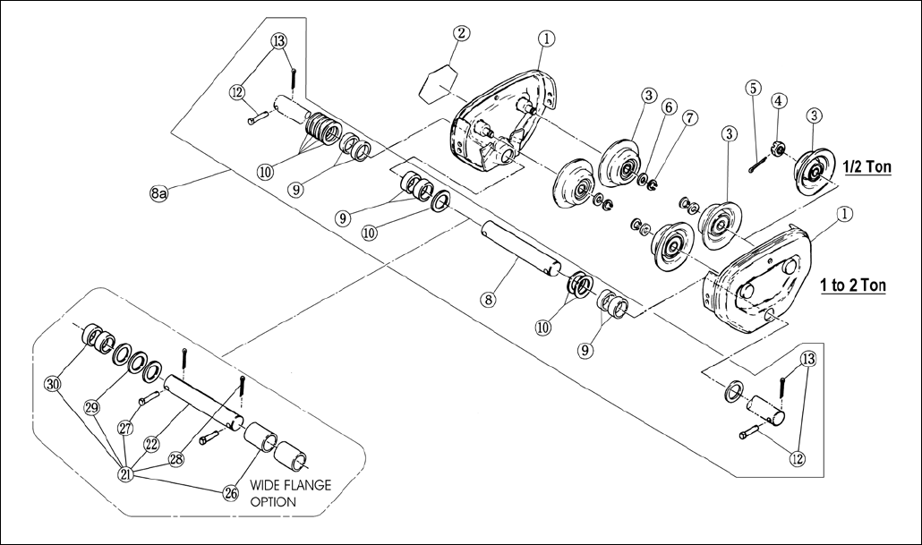
3.1 TS2 Push Trolley Parts – 1/4 to 2 Ton
TS2 Push Trolley 1/4 to 2 Ton
61
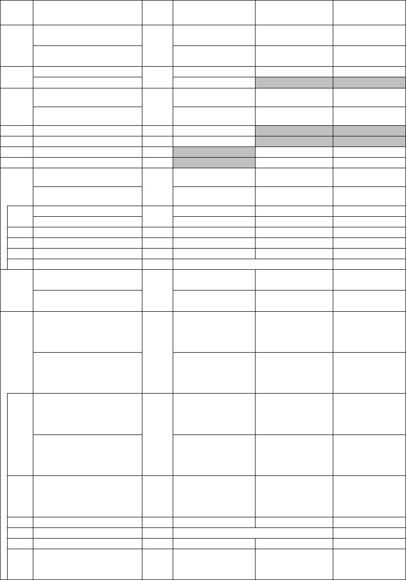
3.1 TS2 Push Trolley Parts – 1/4 to 2 Ton
Figure
No. Part Name
Parts
Per
Trolley
1/2 Ton 1 Ton 2 Ton
1
Side Plate S Assembly –
Standard Wheels 2
37FG0055112 37FG0105112 37FG0205112
Side Plate S Assembly –
Stainless Steel Wheels
37FG0055812 37FG0105812 37FG0205812
2
Name plate B
1
T6G800005P
T6G800010P
T6G800020P
Name plate B – ¼ Ton
80434
3
Track wheel S Assembly –
Standard
4
T6G5102005 T6G5102010 T6G5102020
Track wheel S Assembly –
Stainless Steel
37TW0055102 37TW0105102 37TW0205102
4
Slotted nut
4
J1NL00910100
5
Split pin
4
J1PW06020016
6
Track wheel washer
4
MS104010
MS104020
7
Snap ring
4
J1SS10000015
J1SS10000020
8a
Suspension Shaft Assembly –
Standard Shaft
1
36FG0051115 36FG0101115 36FG0201115
Suspension Shaft Assembly –
Nickel Plated Shaft
37FG0051115 37FG0101115 37FG0201115
8
Suspension Shaft – Standard
1
T7G115005
T7G115010
T7G115020
Suspension Shaft – Nickel Plated
37FG0059115
37FG0109115
37FG0209115
9
Thick spacer (qty)
X
T7G116005(4)
T7G116010(6)
T7G116020(6)
10
Thin spacer (qty)
X
T7G117005(10)
T7G117010(9)
T7G117020(8)
12
Shaft stopper pin
2
T6G156005
T6G156010
T6G156020
13
Split pin
2
J1PW06032020
J1PW06040020
14
Suspender E & G –
White Epoxy Paint 1
36FG0059004 36FG0109004 36FG0209004
Suspender E & G –
Nickel Plated
37FG0059004 37FG0109004 37FG0209004
21
Suspension Shaft Assembly
Extended – Standard Shaft
1
36FG0051136
{4.01 to 8.00”}
36FG0051181
{8.01 to 12.00”}
36FG0101136
{5.01 to 8.00”}
36FG0101181
{8.01 to 12.00”}
36FG0201181
{6.03 to 12.00”}
Suspension Shaft Assembly
Extended – Nickel Plated Shaft
37FG0051136
{4.01 to 8.00”}
37FG0051181
{8.01 to 12.00”}
37FG0101136
{5.01 to 8.00”}
37FG0101181
{8.01 to 12.00”}
37FG0201181
{6.03 to 12.00”}
22
Suspension Shaft – Standard
1
T7PA0059136
{4.01 to 8.00”}
T7PA0059181
{8.01 to 12.00”}
T7GA0109136
{5.01 to 8.00”}
T7GA0109181
{8.01 to 12.00”}
T7GA0209181
{6.03 to 12.00”}
Suspension Shaft – Nickel Plated
37FG0059136
{4.01 to 8.00”}
37FG0059181
{8.01 to 12.00”}
37FG0109136
{5.01 to 8.00”}
37FG0109181
{8.01 to 12.00”}
37FG0209181
{6.03 to 12.00”}
26 Fixing Spacer 2
T7PA0059137
{4.01 to 8.00”}
T7PA0059182
{8.01 to 12.00”}
T7GA0109137
{5.01 to 8.00”}
T7GA0109182
{8.01 to 12.00”}
T7GA0209182
27
Shaft Stopper Pin
*2
T6G156005
T6G156010
T6G156020
28
Split Pin
*2
J1PW06032020
J1PW06040020
29
Thin Spacer
X
T7G117005 (10)
T7G117010 (10)
T7G117020 (10)
30 Thick Spacer X T7G116005 (7)
T7G116010
{5.01 to 8.00”} - (5)
{8.01 to 12.00”} - (7)
T7G116020 (11)
*Quantity is 1 for 2 Ton.
62
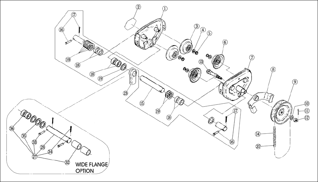
3.2 TS2 Geared Trolley Parts – 1/4 to 2 Ton
TS2 Geared Trolley 1/4 to 2 Ton

63
3.2 TS2 Geared Trolley Parts – 1/4 to 2 Ton
Figure No.
Part Name
Parts Per Trolley
1 Ton
2 Ton
1
Side Plate S Assembly –
Standard Wheels 1
37FG0105112 37FG0205112
Side Plate S Assembly –
Stainless Steel Wheels
37FG0105812 37FG0205812
2
Name plate B**
1
T6G800010G
T6G800020G
3
Track wheel S Assembly – Standard
2
T6G5102010
T6G5102020
Track wheel S Assembly – Stainless Steel
37TW0105102
37FG0205812
4
Track wheel washer
4
MS104010
MS104020
5
Snap ring
4
J1SS10000015
J1SS10000020
6
Track wheel G Assembly – Standard
2
T6G5101010
T6G5101020
Track wheel G Assembly – Stainless Steel
37TW0105101
37TW0205101
7
Side Plate G Assembly
1
37FG0105111 37FG0205111
Side Plate G Assembly – Stainless Steel
Wheels
37FG0105811 37FG0205811
8
Hand chain guide Assembly
1
37FG0105125
9
Hand wheel - Standard
1
T6G123010
Hand Wheel - White Epoxy Paint
37FG0109123
10
Washer
1
J1WB07410120
11
Split pin
1
J1PW06030018
12 Lever nut 1 J1NU00920120
13
Pinion
1
T7GC121010
T7GB121020
14
Hand chain
1
K7RA0500000
15a
Suspension Shaft Assembly –
Standard Shaft
1 36FG0101115 36FG0201115
Suspension Shaft Assembly –
Nickel Plated Shaft
37FG0101115 37FG0201115
15
Suspension Shaft – Standard
1
T7G115010
T7G115020
Suspension Shaft – Nickel Plated
37FG0109115
37FG0209115
16
Shaft stopper pin
2
T6G156010
T6G156020
17
Split pin
2
T6GA0109117(9)
T6GA0209117(8)
18 Thick spacer (qty) X T7G116010(6) T7G116020(6)
19
Thin spacer (qty)
X
T7G117010(9)
T7G117020(8)
23
Suspender E – White Epoxy Paint
1
36FG0109004
36FG0209004
Suspender E – Nickel Plated
37FG0109004
37FG0209004
27
Suspension Shaft Assembly
Extended – Standard Shaft
1
36FG0101136
{4.01 to 8.00”}
36FG0101181
{8.01 to 12.00”}
36FG0201181
{6.03 to 12.00”}
Suspension Shaft Assembly
Extended – Nickel Plated Shaft
37FG0101136
{4.01 to 8.00”}
37FG0101181
{8.01 to 12.00”}
37FG0201181
{6.03 to 12.00”}
28
Suspension Shaft – Standard
1
T7PA0109136
{4.01 to 8.00”}
T7PA0109181
{8.01 to 12.00”}
T7GA0209181
{6.03 to 12.00”}
Suspension Shaft – Nickel Plated
37FG0109136
{4.01 to 8.00”}
37FG0109181
{8.01 to 12.00”}
37FG0209181
{6.03 to 12.00”}
32 Fixing Spacer 2
T7GA0109137
{5.01 to 8.00”}
T7GA0109182
{8.01 to 12.00”}
T7GA0209182
33
Shaft Stopper pin
*2
T6G156010
T6G156020
34
Split Pin
*2
J1PW06032020
J1PW06040020
35
Thin Spacer
X
T7G117010 (10)
T7G117020 (10)
36 Thick Spacer X
T7G116010
{5.01 to 8.00”} - (5)
{8.01 to 12.00”} - (7)
T7G116020 (11)
37 Hand Chain Master Link 1 C1FA0159843N
* Quantity is 1 for 2 Ton.
** For ¼ and ½ Ton capacities, Name Plate B will be relabeled at the factory.

64
www.harringtonhoists.com
Harrington Hoists, Inc. Harrington Hoists – Western Division
401 West End Avenue 2341 Pomona Rd. No. 103
Manheim, PA 17545-1703 Corona, CA 92880-6973
Phone: 717-665-2000 Phone: 951-279-7100
Toll Free: 800-233-3010 Toll Free: 800-317-7111
Fax: 717-665-2861 Fax: 951-279-7500
ER2FGSUP
