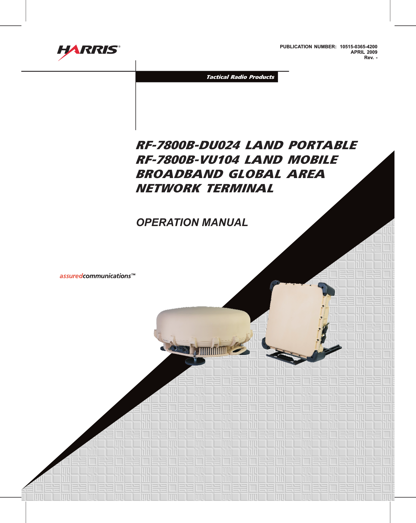
Harris RF Communications Division RF-7800B-VU104 Land Portable BGAN Terminal User Manual user man part 1

Harris Corporation RF Communications Division Land Portable BGAN Terminal user man part 1
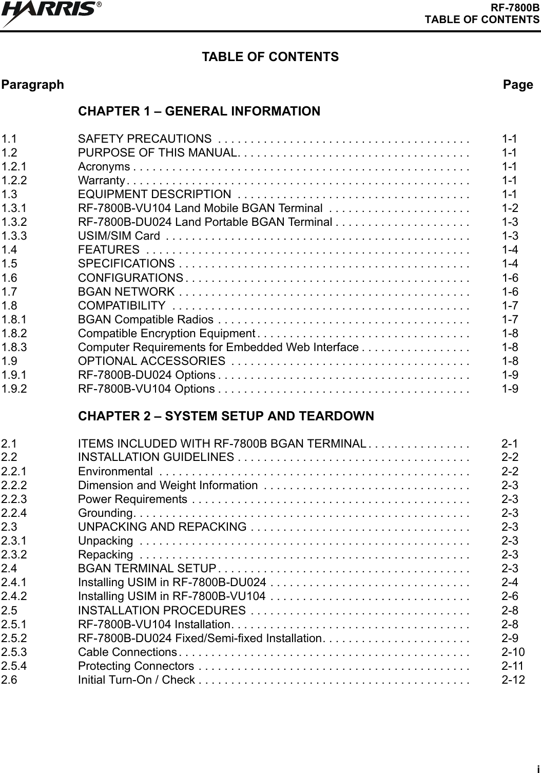
user man part 1

PUBLICATION NUMBER: 10515-0365-4200APRIL 2009Rev. -Tactical Radio ProductsRF-7800B-DU024 LAND PORTABLERF-7800B-VU104 LAND MOBILEBROADBAND GLOBAL AREANETWORK TERMINALOPERATION MANUAL
RLIMITED ONE YEAR WARRANTYHARRIS CORPORATION (RF COMMUNICATIONS DIVISION)FROM HARRIS TO YOU - This warranty is extended to the original buyer and applies to all Harris Corporation, RF CommunicationsDivision equipment purchased and employed for the service normally intended, except those products specifically excluded.NOTE: Terms and conditions of the standard warranty may be superseded by the terms and conditions of your contract.WHAT WE WILL DO - If your Harris Corporation, RF Communications Division equipment purchased from us fails in normal use becauseof a defect in workmanship or materials within one year from the date of shipment, we will repair or replace (at our option) the equipmentor part without charge to you, at our authorized repair center or factory. WHAT YOU MUST DO - You must notify us promptly of a defect within one year from date of shipment. Assuming that Harris concurs thatthe complaint is valid, and is unable to correct the problem without having the equipment shipped to Harris:Customers with equipment purchased for use outside the United States must obtain a Return Material Authorization (RMA) Number for the return of the defective equipment or part to our factory in Rochester, NY, U.S.A., for repair or replacement. You must prepay all transportation, insurance, duty and customs charges. We will pay for return to you of the repaired/replaced equipment or part, C.I.F. destination; you must pay any duty, taxes or customs charges.Customers with equipment purchased for use in the United States must obtain an RMA number, properly pack, insure, prepay the shipping charges and ship the defective equipment or part to our factory or to the Authorized Warranty Repair Center indicated by us.Harris Corporation Telephone:  (585) 242-3561 Toll-free telephone number: (866) 264-8040RF Communications Division Fax:  585-242-4483 https://premier.harris.com/rfcommProduct Service http://www.harris.com1680 University AvenueRochester, NY 14610, U.S.A.Harris will repair or replace the defective equipment or part and pay for its return to you, provided the repair or replacement is due to acause covered by this warranty.WHAT IS NOT COVERED - We regret that we cannot be responsible for:Defects or failures caused by buyer or user abuse or misuse.Defects or failures caused by unauthorized attempts to repair or alter the equipment in any way.Consequential damages incurred by a buyer or user from any cause whatsoever, including, but not limited to transportation, non-Harris repair or service costs, downtime costs, costs for substituting equipment or loss of anticipated profits or revenue.The performance of the equipment when used in combination with equipment not purchased from Harris.HARRIS MAKES NO OTHER WARRANTIES BEYOND THE EXPRESS WARRANTY AS CONTAINED HEREIN. ALL EXPRESS OR IMPLIED WARRANTIES OF FITNESS FOR A PARTICULAR PURPOSE OR MERCHANTABILITY ARE EXCLUDED.SERVICE WARRANTY - Any repair service performed by Harris under this limited warranty is warranted to be free from defects in materialor workmanship for sixty days from date of repair. All terms and exclusions of this limited warranty apply to the service warranty.IMPORTANT - Customers who purchased equipment must obtain an RMA before shipping the defective equipment to us. Failure to obtainan RMA before shipment may result in a delay in the repair/replacement and return of your equipment.IF YOU HAVE ANY QUESTIONS - Concerning this warranty or equipment sales or services, please contact our Product ServiceDepartment.
PUBLICATION NUMBER: 10515-0365-4200APRIL 2009Rev. -HARRIS   CORPORATION   RF   COMMUNICATIONS   DIVISION1680 University Avenue    Rochester, New York  14610-1887   USA               Tel: 585-244-5830. Fax: 585-242-4755.  http://www.harris.comRInformation and descriptions contained herein are the property of Harris Corporation. Suchinformation and descriptions may not be copied or reproduced by any means, or disseminatedor distributed without the express prior written permission of Harris Corporation, RFCommunications Division, 1680 University Avenue, Rochester, New York 14610-1887.Copyright  2009By Harris CorporationAll Rights ReservedFirmware Version 5.1.1.2RF-7800B-DU024 LAND PORTABLERF-7800B-VU104 LAND MOBILEBROADBAND GLOBAL AREANETWORK TERMINALOPERATION MANUAL
iRF-7800BTABLE OF CONTENTSTABLE OF CONTENTSParagraph PageRCHAPTER 1 – GENERAL INFORMATION1.1 SAFETY PRECAUTIONS  . . . . . . . . . . . . . . . . . . . . . . . . . . . . . . . . . . . . . . . 1-11.2 PURPOSE OF THIS MANUAL. . . . . . . . . . . . . . . . . . . . . . . . . . . . . . . . . . . . 1-11.2.1 Acronyms . . . . . . . . . . . . . . . . . . . . . . . . . . . . . . . . . . . . . . . . . . . . . . . . . . . . 1-11.2.2 Warranty . . . . . . . . . . . . . . . . . . . . . . . . . . . . . . . . . . . . . . . . . . . . . . . . . . . . . 1-11.3 EQUIPMENT DESCRIPTION  . . . . . . . . . . . . . . . . . . . . . . . . . . . . . . . . . . . . 1-11.3.1 RF-7800B-VU104 Land Mobile BGAN Terminal  . . . . . . . . . . . . . . . . . . . . . . 1-21.3.2 RF-7800B-DU024 Land Portable BGAN Terminal . . . . . . . . . . . . . . . . . . . . . 1-31.3.3 USIM/SIM Card  . . . . . . . . . . . . . . . . . . . . . . . . . . . . . . . . . . . . . . . . . . . . . . . 1-31.4 FEATURES  . . . . . . . . . . . . . . . . . . . . . . . . . . . . . . . . . . . . . . . . . . . . . . . . . . 1-41.5 SPECIFICATIONS . . . . . . . . . . . . . . . . . . . . . . . . . . . . . . . . . . . . . . . . . . . . . 1-41.6 CONFIGURATIONS . . . . . . . . . . . . . . . . . . . . . . . . . . . . . . . . . . . . . . . . . . . . 1-61.7 BGAN NETWORK . . . . . . . . . . . . . . . . . . . . . . . . . . . . . . . . . . . . . . . . . . . . . 1-61.8 COMPATIBILITY  . . . . . . . . . . . . . . . . . . . . . . . . . . . . . . . . . . . . . . . . . . . . . . 1-71.8.1 BGAN Compatible Radios . . . . . . . . . . . . . . . . . . . . . . . . . . . . . . . . . . . . . . . 1-71.8.2 Compatible Encryption Equipment . . . . . . . . . . . . . . . . . . . . . . . . . . . . . . . . . 1-81.8.3 Computer Requirements for Embedded Web Interface . . . . . . . . . . . . . . . . . 1-81.9 OPTIONAL ACCESSORIES  . . . . . . . . . . . . . . . . . . . . . . . . . . . . . . . . . . . . . 1-81.9.1 RF-7800B-DU024 Options . . . . . . . . . . . . . . . . . . . . . . . . . . . . . . . . . . . . . . . 1-91.9.2 RF-7800B-VU104 Options . . . . . . . . . . . . . . . . . . . . . . . . . . . . . . . . . . . . . . . 1-9CHAPTER 2 – SYSTEM SETUP AND TEARDOWN2.1 ITEMS INCLUDED WITH RF-7800B BGAN TERMINAL . . . . . . . . . . . . . . . . 2-12.2 INSTALLATION GUIDELINES . . . . . . . . . . . . . . . . . . . . . . . . . . . . . . . . . . . . 2-22.2.1 Environmental  . . . . . . . . . . . . . . . . . . . . . . . . . . . . . . . . . . . . . . . . . . . . . . . . 2-22.2.2 Dimension and Weight Information  . . . . . . . . . . . . . . . . . . . . . . . . . . . . . . . . 2-32.2.3 Power Requirements . . . . . . . . . . . . . . . . . . . . . . . . . . . . . . . . . . . . . . . . . . . 2-32.2.4 Grounding. . . . . . . . . . . . . . . . . . . . . . . . . . . . . . . . . . . . . . . . . . . . . . . . . . . . 2-32.3 UNPACKING AND REPACKING . . . . . . . . . . . . . . . . . . . . . . . . . . . . . . . . . . 2-32.3.1 Unpacking  . . . . . . . . . . . . . . . . . . . . . . . . . . . . . . . . . . . . . . . . . . . . . . . . . . . 2-32.3.2 Repacking  . . . . . . . . . . . . . . . . . . . . . . . . . . . . . . . . . . . . . . . . . . . . . . . . . . . 2-32.4 BGAN TERMINAL SETUP . . . . . . . . . . . . . . . . . . . . . . . . . . . . . . . . . . . . . . . 2-32.4.1 Installing USIM in RF-7800B-DU024 . . . . . . . . . . . . . . . . . . . . . . . . . . . . . . . 2-42.4.2 Installing USIM in RF-7800B-VU104 . . . . . . . . . . . . . . . . . . . . . . . . . . . . . . . 2-62.5 INSTALLATION PROCEDURES  . . . . . . . . . . . . . . . . . . . . . . . . . . . . . . . . . . 2-82.5.1 RF-7800B-VU104 Installation. . . . . . . . . . . . . . . . . . . . . . . . . . . . . . . . . . . . . 2-82.5.2 RF-7800B-DU024 Fixed/Semi-fixed Installation. . . . . . . . . . . . . . . . . . . . . . . 2-92.5.3 Cable Connections. . . . . . . . . . . . . . . . . . . . . . . . . . . . . . . . . . . . . . . . . . . . . 2-102.5.4 Protecting Connectors . . . . . . . . . . . . . . . . . . . . . . . . . . . . . . . . . . . . . . . . . . 2-112.6 Initial Turn-On / Check . . . . . . . . . . . . . . . . . . . . . . . . . . . . . . . . . . . . . . . . . . 2-12
iiRF-7800BTABLE OF CONTENTSTABLE OF CONTENTS – ContinuedParagraph PageRCHAPTER 3 – OPERATION3.1 INTRODUCTION . . . . . . . . . . . . . . . . . . . . . . . . . . . . . . . . . . . . . . . . . . . . . .  3-13.2 OPERATIONS TASK SUMMARY  . . . . . . . . . . . . . . . . . . . . . . . . . . . . . . . . .  3-13.3 MAKE CABLE CONNECTIONS. . . . . . . . . . . . . . . . . . . . . . . . . . . . . . . . . . .  3-13.3.1 Data Connections. . . . . . . . . . . . . . . . . . . . . . . . . . . . . . . . . . . . . . . . . . . . . .  3-23.3.1.1 Connect Data by Ethernet . . . . . . . . . . . . . . . . . . . . . . . . . . . . . . . . . . . . . . .  3-23.3.1.2 Connect Data by USB  . . . . . . . . . . . . . . . . . . . . . . . . . . . . . . . . . . . . . . . . . .  3-33.3.1.3 Connect Data by ISDN. . . . . . . . . . . . . . . . . . . . . . . . . . . . . . . . . . . . . . . . . .  3-43.3.1.4 Connect Data to Radio. . . . . . . . . . . . . . . . . . . . . . . . . . . . . . . . . . . . . . . . . .  3-43.3.2 Power Connections . . . . . . . . . . . . . . . . . . . . . . . . . . . . . . . . . . . . . . . . . . . .  3-53.3.2.1 Connect BGAN Terminal Power to Commercial Vehicle 12 VDC  . . . . . . . . .  3-53.3.2.2 Connect BGAN Terminal Power to AC to DC Power Supply . . . . . . . . . . . . .  3-53.3.2.3 Connect BGAN Terminal Power to Battery  . . . . . . . . . . . . . . . . . . . . . . . . . .  3-53.3.2.4 Connect BGAN Terminal Power to 26 VDC Power Supply . . . . . . . . . . . . . .  3-63.3.2.5 Connect RF-7800B-DU024 Power to BGAN Battery Box Kit. . . . . . . . . . . . .  3-73.4 USING RF-7800B-DU024 TERMINAL STAND . . . . . . . . . . . . . . . . . . . . . . .  3-83.5 RF-7800B-DU024 INITIAL SETTINGS AND TURN-ON  . . . . . . . . . . . . . . . .  3-93.6 RF-7800B-VU104 INITIAL SETTINGS AND TURN-ON  . . . . . . . . . . . . . . . .  3-103.7 BGAN SERVICES . . . . . . . . . . . . . . . . . . . . . . . . . . . . . . . . . . . . . . . . . . . . .  3-113.7.1 Obtaining a GPS Fix  . . . . . . . . . . . . . . . . . . . . . . . . . . . . . . . . . . . . . . . . . . .  3-113.7.2 GPS and BGAN Registration . . . . . . . . . . . . . . . . . . . . . . . . . . . . . . . . . . . . .  3-113.7.3 ISDN Voice Telephony Services. . . . . . . . . . . . . . . . . . . . . . . . . . . . . . . . . . .  3-123.7.3.1 Dialing  . . . . . . . . . . . . . . . . . . . . . . . . . . . . . . . . . . . . . . . . . . . . . . . . . . . . . .  3-123.7.3.2 Multi-Subscriber Numbering (MSN) . . . . . . . . . . . . . . . . . . . . . . . . . . . . . . . .  3-123.7.4 Data Services. . . . . . . . . . . . . . . . . . . . . . . . . . . . . . . . . . . . . . . . . . . . . . . . .  3-123.7.5 Virtual Private Network (VPN) Connections. . . . . . . . . . . . . . . . . . . . . . . . . .  3-13CHAPTER 4 – CONFIGURATION4.1 INTRODUCTION . . . . . . . . . . . . . . . . . . . . . . . . . . . . . . . . . . . . . . . . . . . . . .  4-14.2 CONFIGURATION CAPABILITIES  . . . . . . . . . . . . . . . . . . . . . . . . . . . . . . . .  4-14.2.1 RF-7800B-VU104 Land Mobile BGAN Terminal  . . . . . . . . . . . . . . . . . . . . . .  4-14.2.2 RF-7800B-DU024 Land Portable BGAN Terminal . . . . . . . . . . . . . . . . . . . . .  4-14.3 CONFIGURATION PARAMETERS . . . . . . . . . . . . . . . . . . . . . . . . . . . . . . . .  4-24.3.1 Properties Page . . . . . . . . . . . . . . . . . . . . . . . . . . . . . . . . . . . . . . . . . . . . . . .  4-24.3.2 Setup Page  . . . . . . . . . . . . . . . . . . . . . . . . . . . . . . . . . . . . . . . . . . . . . . . . . .  4-44.3.3 Statistics Page . . . . . . . . . . . . . . . . . . . . . . . . . . . . . . . . . . . . . . . . . . . . . . . .  4-74.3.4 PDP Contexts. . . . . . . . . . . . . . . . . . . . . . . . . . . . . . . . . . . . . . . . . . . . . . . . .  4-84.3.4.1 Activating a PDP Context. . . . . . . . . . . . . . . . . . . . . . . . . . . . . . . . . . . . . . . .  4-84.3.4.2 Activating Multiple PDP Contexts. . . . . . . . . . . . . . . . . . . . . . . . . . . . . . . . . .  4-104.3.5 IP ACA Properties  . . . . . . . . . . . . . . . . . . . . . . . . . . . . . . . . . . . . . . . . . . . . .  4-114.3.5.1 ACA settings for TE with Static IP address: . . . . . . . . . . . . . . . . . . . . . . . . . .  4-124.3.5.2 ACA settings for TE using DHCP assigned IP address . . . . . . . . . . . . . . . . .  4-124.3.6 ISDN Interface Properties  . . . . . . . . . . . . . . . . . . . . . . . . . . . . . . . . . . . . . . .  4-134.3.7 Antenna Status. . . . . . . . . . . . . . . . . . . . . . . . . . . . . . . . . . . . . . . . . . . . . . . .  4-14
iiiRF-7800BTABLE OF CONTENTSTABLE OF CONTENTS – ContinuedParagraph PageRCHAPTER 5 – SCHEDULED MAINTENANCE5.1 PREVENTIVE MAINTENANCE . . . . . . . . . . . . . . . . . . . . . . . . . . . . . . . . . . . 5-15.2 CORRECTIVE MAINTENANCE. . . . . . . . . . . . . . . . . . . . . . . . . . . . . . . . . . . 5-15.2.1 Troubleshooting Procedures  . . . . . . . . . . . . . . . . . . . . . . . . . . . . . . . . . . . . . 5-25.2.1.1 Power-on BIT Faults. . . . . . . . . . . . . . . . . . . . . . . . . . . . . . . . . . . . . . . . . . . . 5-25.2.1.2 Operator-Initiated BIT Faults  . . . . . . . . . . . . . . . . . . . . . . . . . . . . . . . . . . . . . 5-25.2.1.3 Run-Time Faults. . . . . . . . . . . . . . . . . . . . . . . . . . . . . . . . . . . . . . . . . . . . . . . 5-25.2.1.4 Non-BIT Faults . . . . . . . . . . . . . . . . . . . . . . . . . . . . . . . . . . . . . . . . . . . . . . . . 5-25.3 BATTERIES . . . . . . . . . . . . . . . . . . . . . . . . . . . . . . . . . . . . . . . . . . . . . . . . . . 5-75.3.1 Battery Life . . . . . . . . . . . . . . . . . . . . . . . . . . . . . . . . . . . . . . . . . . . . . . . . . . . 5-85.3.2 Battery Safety. . . . . . . . . . . . . . . . . . . . . . . . . . . . . . . . . . . . . . . . . . . . . . . . . 5-85.3.3 Rechargeable Battery Packs . . . . . . . . . . . . . . . . . . . . . . . . . . . . . . . . . . . . . 5-95.3.4 Disposing of Lithium Batteries . . . . . . . . . . . . . . . . . . . . . . . . . . . . . . . . . . . . 5-9APPENDIX A - TECHNICAL INFORMATIONA.1 CHASSIS CONNECTOR PINOUT DATA. . . . . . . . . . . . . . . . . . . . . . . . . . . . A-1A.1.1 Mating Connectors . . . . . . . . . . . . . . . . . . . . . . . . . . . . . . . . . . . . . . . . . . . . . A-2APPENDIX B - GLOSSARYB.1 GLOSSARY . . . . . . . . . . . . . . . . . . . . . . . . . . . . . . . . . . . . . . . . . . . . . . . . . . B-1
ivRF-7800BTABLE OF CONTENTSLIST OF FIGURESFigure PageR1-1 RF-7800B-VU104 Land Mobile BGAN Terminal  . . . . . . . . . . . . . . . . . . . . . .  1-21-2 RF-7800B-DU024 Land Portable BGAN Terminal . . . . . . . . . . . . . . . . . . . . .  1-31-3 BGAN Worldwide Coverage. . . . . . . . . . . . . . . . . . . . . . . . . . . . . . . . . . . . . .  1-72-1 Items Included with RF-7800B-VU104. . . . . . . . . . . . . . . . . . . . . . . . . . . . . .  2-12-2 Items Included with RF-7800B-DU024. . . . . . . . . . . . . . . . . . . . . . . . . . . . . .  2-22-3 Accessing the USIM Card Holder on RF-7800B-DU024 . . . . . . . . . . . . . . . .  2-42-4 Opening the USIM Card Holder on RF-7800B-DU024  . . . . . . . . . . . . . . . . .  2-52-5 Placing the USIM Card in Holder on RF-7800B-DU024  . . . . . . . . . . . . . . . .  2-52-6  USIM Card Located in Holder on RF-7800B-DU024  . . . . . . . . . . . . . . . . . .  2-52-7 Accessing the USIM Card Holder and Drain Holes on RF-7800B-VU104 . . .  2-72-8 Placing the USIM Card in Holder on RF-7800B-VU104. . . . . . . . . . . . . . . . .  2-72-9 Pole Mount Option . . . . . . . . . . . . . . . . . . . . . . . . . . . . . . . . . . . . . . . . . . . . .  2-92-10 Fixed Mount Option . . . . . . . . . . . . . . . . . . . . . . . . . . . . . . . . . . . . . . . . . . . .  2-102-11 Cabling Options . . . . . . . . . . . . . . . . . . . . . . . . . . . . . . . . . . . . . . . . . . . . . . .  2-113-1 RF-7800B-VU104 Connectors . . . . . . . . . . . . . . . . . . . . . . . . . . . . . . . . . . . .  3-13-2 RF-7800B-DU024 Connectors. . . . . . . . . . . . . . . . . . . . . . . . . . . . . . . . . . . .  3-23-3 BGAN Ethernet Cable, 12043-0833-A010 . . . . . . . . . . . . . . . . . . . . . . . . . . .  3-23-4 Standalone Ethernet and ISDN Cable, 12043-0834-A010 (Optional) . . . . . .  3-33-5 Standalone USB & ISDN Cable, 12043-0836-A010 (Optional) . . . . . . . . . . .  3-33-6 Standalone ISDN Cable, 12043-0835-A010 (Optional) . . . . . . . . . . . . . . . . .  3-43-7 BGAN to Radio Black Ethernet Cable, 12043-0830-A006 (Optional)  . . . . . .  3-43-8 BGAN to Radio Black Ethernet and ISDN Cable, 12043-0831-A006 (Optional) . . . . . . . . . . . . . . . . . . . . . . . . . . . . . . . . . . . . . . . . . . . . . . . . .  3-43-9 BGAN, DC Power to Vehicle 12 VDC, 12043-0843-A015 . . . . . . . . . . . . . . .  3-53-10 BGAN, AC to DC Power Supply Assembly, 12043-0844-A1 . . . . . . . . . . . . .  3-53-11 Cable Assembly, BGAN DC Power to 2 Leads, 12043-0846-A0xx . . . . . . . .  3-53-12 Cable Assembly, BGAN DC Power to 4 Leads, 12043-0840-A0xx . . . . . . . .  3-63-13 AC/DC Power Supply Cable (RF-505X-PS), 12043-0841-A0xx  . . . . . . . . . .  3-63-14 BGAN DC Power to 26 VDC/Remote On/Off, 12043-0842-A0xx  . . . . . . . . .  3-63-15 Battery Box Cable, 12043-0850-A006 . . . . . . . . . . . . . . . . . . . . . . . . . . . . . .  3-73-16 Battery Box Kit, 12091-4010-01. . . . . . . . . . . . . . . . . . . . . . . . . . . . . . . . . . .  3-73-17 Open RF-7800B-DU024 Terminal Stand . . . . . . . . . . . . . . . . . . . . . . . . . . . .  3-83-18 Slide Out Stabilizer. . . . . . . . . . . . . . . . . . . . . . . . . . . . . . . . . . . . . . . . . . . . .  3-93-19 RF-7800B-DU024 ON, OFF, AUDIO Switch  . . . . . . . . . . . . . . . . . . . . . . . . .  3-104-1 BGAN Terminal Properties . . . . . . . . . . . . . . . . . . . . . . . . . . . . . . . . . . . . . . .  4-34-2 BGAN Terminal Setup  . . . . . . . . . . . . . . . . . . . . . . . . . . . . . . . . . . . . . . . . . .  4-64-3 BGAN Terminal Statistics . . . . . . . . . . . . . . . . . . . . . . . . . . . . . . . . . . . . . . . .  4-74-4 BGAN Terminal Connections . . . . . . . . . . . . . . . . . . . . . . . . . . . . . . . . . . . . .  4-94-5 BGAN Terminal with Multiple Connections. . . . . . . . . . . . . . . . . . . . . . . . . . .  4-104-6 BGAN Terminal IP ACA Properties  . . . . . . . . . . . . . . . . . . . . . . . . . . . . . . . .  4-114-7 BGAN Terminal ISDN Interface Properties  . . . . . . . . . . . . . . . . . . . . . . . . . .  4-134-8 BGAN Terminal Antenna Status . . . . . . . . . . . . . . . . . . . . . . . . . . . . . . . . . . .  4-15A-1 RF-7800B Data and Power Connector Pinouts . . . . . . . . . . . . . . . . . . . . . . .  A-1
vRF-7800BTABLE OF CONTENTSLIST OF TABLESTable PageR1-1 RF-7800B BGAN Terminal Specifications  . . . . . . . . . . . . . . . . . . . . . . . . . . . 1-44-1 Antenna Status ATB State  . . . . . . . . . . . . . . . . . . . . . . . . . . . . . . . . . . . . . . . 4-154-3 ABIT Test Results. . . . . . . . . . . . . . . . . . . . . . . . . . . . . . . . . . . . . . . . . . . . . . 4-164-2 Satellite Frequencies . . . . . . . . . . . . . . . . . . . . . . . . . . . . . . . . . . . . . . . . . . . 4-165-1 Daily Preventive Maintenance Checks and Services . . . . . . . . . . . . . . . . . . . 5-15-2 Weekly Preventive Maintenance Checks and Services . . . . . . . . . . . . . . . . . 5-15-3 Run-Time BIT Faults, Descriptions, and Corrective Action  . . . . . . . . . . . . . . 5-25-4 Non-BIT Troubleshooting . . . . . . . . . . . . . . . . . . . . . . . . . . . . . . . . . . . . . . . . 5-3A-1 DATA  . . . . . . . . . . . . . . . . . . . . . . . . . . . . . . . . . . . . . . . . . . . . . . . . . . . . . . . A-1A-2 POWER . . . . . . . . . . . . . . . . . . . . . . . . . . . . . . . . . . . . . . . . . . . . . . . . . . . . . A-1A-3 Connectors and Mating Connector Part Numbers . . . . . . . . . . . . . . . . . . . . . A-2
viRF-7800BTABLE OF CONTENTSRThis page intentionally left blank.
viiRF-7800BSAFETY SUMMARYRSAFETY SUMMARY1. INTRODUCTIONAll operators and maintenance personnel must observe the following safety precautions during operation and maintenance of this equipment. Specific warnings and cautions are provided in the manual and at the end of this Safety Summary. Warnings, Cautions, and Notes appear before various steps in the manual and will be used as follows:WARNING Used when injury or death to personnel and damage to equipment is possibleCAUTION Used when there is a possibility of damage to equipmentNOTE Used to alert personnel to a condition that requires emphasis2. PERSONNEL AND EQUIPMENT SAFETYBasic safety precautions consider factors involved in protecting personnel from injury or death. Electrical, mechanical, thermal, electromagnetic radiation (EMR), or chemical hazards are the most common types of hazards found in electronic equipment. The following are types of hazards that may exist:ELECTRICAL Hazardous voltage and current levels may exist throughout the equipment. Contactwith these hazards could cause electrocution, electrical shock, burns, or injury due to involuntary reflexes of the body.THERMAL Burn hazards may exist in the equipment that could cause personal injuries and/orserious equipment damage. Internal surfaces of the equipment may be in excess of65C, the point at which personnel could be burned. Extreme caution should be usedwhen working with any hot assemblies (for example, power supply or poweramplifier assemblies). Physical injury or damage may result to personnel and/orequipment as a result of a reflex action to a burn.EMR Overexposure to electromagnetic radiation from amplified radio frequenciesmay produce a health hazard.3. OPERATIONAL AND MAINTENANCE SAFETY GUIDELINESGood safety discipline is critical to prevent injury to personnel. All other safety measures are useless if personnel do not observe the safety precautions and do not follow safety disciplines. Once aware of a hazard, personnel should ensure that all other personnel are aware of the hazard. The following basic safety disciplines are stressed:a. Read a procedure entirely before performing it. Personnel must always perform each assigned task in a safe manner.b. Prior to applying equipment power after maintenance, personnel must ensure that all unsecured hand tools and test equipment are disconnected from the serviced/maintained equipment and properly stored.c. Power to the equipment must be removed before a piece of equipment is removed.d. Extreme care must be used when adjusting or working on operating equipment. Voltages in excess of 70 V or current sources in excess of 25 A are covered with barriers. Barriers include warning information about the hazard encountered upon barrier removal.
viiiRF-7800BSAFETY SUMMARYRe. Personnel must react when someone is being electrically shocked. Perform the following steps:1. Shut off power.2. Call for help.3. Administer first aid if qualified.Under no circumstances should a person come directly in contact with the body unless the power has been removed. When immediate removal of the power is not possible, personnel must use a non-con-ductive material to try to jolt or pry the body away from the point of shock.f. Personnel should work with one hand whenever possible to prevent electrical current from passing through vital organs of the body. In addition, personnel must never work alone. Someone must be available in the immediate area to render emergency first aid, if necessary.g. Lifting can cause injury. Items weighing more than 37 pounds must be lifted by two or more people.h. Some electrolytic capacitors contain aluminum oxide or tantalum. If connected incorrectly, the capacitor will explode when power is applied. Extreme care must be used when replacing and connecting these capacitors. The capacitor terminals must always be connected using the correct polarity:  positive to positive and negative to negative.The next section contains general safety precautions not directly related to specific procedures or equipment. These precautions are oriented toward the maintenance technician. However, all personnel must understand and apply these precautions during the many phases of operation and maintenance of the equipment. The following precautions must be observed:DO NOT SERVICE EQUIPMENT ALONENever work on electrical equipment unless another person familiar with the operation and hazards of the equipment is near. When the maintenance technician is aided by operators, ensure that operators are aware of the hazards.GROUNDINGAlways ensure that all equipment and assemblies are properly grounded when operating or servicing.TURN OFF POWER AND GROUND CAPACITORSWhenever possible, power to equipment should be turned off before beginning work on the equipment. Be sure to ground all capacitors that are potentially dangerous.KEEP AWAY FROM LIVE CIRCUITSOperators and maintainers must observe all safety regulations at all times. Do not change components or make adjustments inside equipment with a high voltage supply on unless required by the procedure. Under certain conditions, dangerous potentials may exist in circuits with power controls off, due to charges retained by capacitors.DO NOT BYPASS INTERLOCKSDo not bypass any interlocks unnecessarily. If it is necessary to employ an interlock bypass for equipment servicing, use extreme care not to come in contact with hazardous voltages.
ixRF-7800BSAFETY SUMMARYRUSE CARE HANDLING HEAVY EQUIPMENTNever attempt to lift large assemblies or equipment without knowing their weight. Use enough personnel or a mechanical lifting device to properly handle the item without causing personal injury.HEED WARNINGS AND CAUTIONSSpecific warnings and cautions are provided to ensure the safety and protection of personnel and equipment. Be familiar with and strictly follow all warnings and cautions on the equipment and in technical manuals.PROTECTIVE EYEWEARAll personnel must wear protective eyewear when servicing or maintaining equipment. Protective eyewear must be worn at all times when using tools.4. PROTECTION OF STATIC-SENSITIVE DEVICESDiode input-protection is provided on all CMOS devices. This protection is designed to guard against adverse electrical conditions such as electrostatic discharge. Although most static-sensitive devices contain protective circuitry, several precautionary steps should be taken to avoid the application of potentially damaging voltages to the inputs of the device. To protect static-sensitive devices from damage, the following precautions should be observed.a. Keep all static-sensitive devices in their protective packaging until needed. This packaging is conductive and should provide adequate protection for the device. Storing or transporting these devices in conventional plastic containers could be destructive to the device.b. Disconnect power prior to insertion or extraction of these devices. This also applies to PWBs containing such devices.c. Double check test equipment voltages and polarities prior to conducting any tests.d. Avoid contact with the leads of the device. The component should always be handled carefully by the ends or side opposite the leads.e. Avoid contact between PWB circuits or component leads and synthetic clothing.f. Use only soldering irons and tools that are properly grounded. Ungrounded soldering tips or tools can destroy these devices. SOLDERING GUNS MUST NEVER BE USED.5. FCC COMPLIANCEThis device conforms to the FCC rules. Any changes or modifications to Harris Corporations equipment, not expressly approved by Harris Corporation could void the user's authority to operate the equipment.To comply with FCC RF exposure requirements, this device must be operated with a minimum separation distance of 20 cm or more from a person's body. Other operating configurations should be avoided.This device complies with Part 15 of the FCC Rules. Operation is subject to the following two conditions; (1) this device may not cause harmful interference, and (2) this device must accept any interference received, including interference that may cause undesired operation.
xRF-7800BSAFETY SUMMARYR6. DECLARATION OF CONFORMITYHarris Corporation RF Communications Division of Rochester NY, USA, declares under our sole responsibility that the product Harris RF-7800B-VU104 and RF-7800B-DU024 Satellite IP Terminal to which this declaration relates, is in conformity with the following standards and/or other normative documents:ETSI EN 301 444, ETSI EN 301 489-1, ETSI EN 301 489-20, EN 60950-1, Council Recommendation 1999/519/EC.We hereby declare that all essential radio test suites have been carried out and that the above named product is in conformity to all the essential requirements of R&TTE Directive 1999/5/EC.The technical documentation relevant to the above equipment will be held at:Harris Corporation RF Communications Division 1680 University Avenue Rochester, New York 146107. EUROPEAN UNION WASTE ELECTRICAL AND ELECTRONIC EQUIPMENT DIRECTIVESThe European Union (EU) directive on waste electrical and electronic equipment mandates recycling of electrical and electronic equipment throughout the EU by August 13, 2005.Unless otherwise noted, all products, assemblies, and sub-assemblies manufactured by Harris and its sub-contractors will be compliant with this directive and any subsequent revisions or amendments. This product carries the WEEE label below to demonstrate compliance.For addition information, contact Harris Corporation at: www.harris.com.
RF-7800BRRF-7800B-DU024 LAND PORTABLERF-7800B-VU104 LAND MOBILEBROADBAND GLOBAL AREANETWORK TERMINALOPERATION MANUAL
1-1RF-7800BGENERAL INFORMATIONRCHAPTER 1GENERAL INFORMATION1.1 SAFETY PRECAUTIONSAll safety precautions necessary for the protection of personnel and equipment are cross-referenced in the following list. The WARNING or CAUTION is referenced to the paragraph number where it is used in the manual, and a brief subject phrase indicating the content is provided. Read these items in their entirety before performing the referenced procedure.WARNING - Paragraph 2.2.1 - Do not operate the BGAN terminal during electrical storms.WARNING - Paragraph 2.2.1 - Never use the BGAN terminal where blasting work is in progress.CAUTION - Paragraph 2.2.1 - Avoid placing BGAN terminal near any source of heat such as an open flame.CAUTION - Paragraph 3.5 - Do not stand in front of the BGAN terminal.WARNING - Paragraph 5.3.3 - Do not overcharge, short circuit, incinerate, or mutilate rechargeable batteries.WARNING - Paragraph 5.3.4 - Do not dispose of batteries in uncontrolled trash, as batteries may contain hazardous materials.1.2 PURPOSE OF THIS MANUALThis operation manual provides operating instructions, as well as technical information required to support Level I (operator) Maintenance of RF-7800B Broadband Global Area Network (BGAN) Terminals (referred to throughout this manual as BGAN terminal).1.2.1 AcronymsAll acronyms used are contained in the Glossary at the back of this manual. Refer to Appendix B.1.2.2 WarrantyFor warranty information, refer to the inside front cover of this manual.1.3 EQUIPMENT DESCRIPTIONThe Harris RF-7800B Land Mobile and Land Portable BGAN Terminals provide a high-performance Satellite Communications (SATCOM) solution with reliable voice and broadband data connectivity for Beyond-Line-of-Sight (BLOS) SATCOM-on-the-Move (SOTM) and SATCOM-on-the-Quick-Halt (SOQH) applications. The BGAN SATCOM spectrum (L-Band) utilizes the International Marine/Maritime Satellite (INMARSAT) 4 constellation, providing wideband Internet Protocol (IP) data throughput up to 492 kbps. These high data throughput backbone links can interconnect warfighter tactical networks to Tactical Operation Centers (TOC) as well as beyond line of sight vehicles or regional headquarters.As a standalone device integrated into an existing network infrastructure, the BGAN terminals allow an Integrated Services Digital Network (ISDN)-capable device to be plugged in for circuit switched mode use across the BGAN network. This ISDN interface provides the ability to connect directly to the Public Switched Telephone Network (PSTN) for telephony and data communications. This interface also provides the ability to connect Secure Terminal Equipment (STE) directly to the BGAN terminal for secure telephone calls.
1-2RF-7800BGENERAL INFORMATIONRRF-7800B BGAN terminal products ensure a seamless tactical network-centric BLOS connectivity interface to existing Falcon III tactical networks. When the AN/PRC-117G or RF-7800M-MP manpack radio is set up as a BGAN gateway using a BGAN-enabled preset, the BGAN terminal provides BLOS range extension of data networking capabilities through simultaneous operation with mobile wideband networked line-of-sight (LOS) nodes. The Falcon III radios remote control the BGAN terminals to automatically create a connection to the INMARSAT network, providing a fully integrated end-to-end IP data network for assured and secured communications.BGAN terminals can be configured and actively controlled via an embedded web-based interface. The web interface is used to configure the BGAN terminal to meet system architecture requirements, including all IP networking properties, automatic network connections, inactivity timers and ISDN properties. BGAN satellite connections can be initiated and monitored through the web interface. Active connection status is provided on every page. Network traffic usage is tracked in the amount of megabytes (Background Mode) and minutes (Streaming Mode), both on a mission basis as well as through the BGAN terminal’s lifetime. Overall BGAN terminal status and version information may be viewed through the web interface.1.3.1 RF-7800B-VU104 Land Mobile BGAN TerminalThe Harris RF-7800B-VU104 Land Mobile BGAN Terminal is a Class 10 BGAN SOTM Terminal that provides data rates of up to 492 kbps while on the move. See Figure 1-1. The BGAN terminal will send and receive IP packet data via the Ethernet and Universal Serial Bus (USB) simultaneously with circuit switched telephony and data via the ISDN interface over the INMARSAT BGAN satellite network.RF-7800B-VU104 may be permanently mounted on a vehicle and is capable of operating at speeds of up to 70 mph. Continuous tracking with the INMARSAT satellite is provided to achieve successful communications. Full network connectivity is uninterrupted when vehicular velocity of motion is up to 100 degrees per second, and vehicular acceleration is up to 100 degrees per second squared in both azimuth and elevation, with simultaneous random pitch and roll.Figure 1-1. RF-7800B-VU104 Land Mobile BGAN TerminalCL-0365-4200-0001
1-3RF-7800BGENERAL INFORMATIONR1.3.2 RF-7800B-DU024 Land Portable BGAN TerminalThe RF-7800B-DU024 Land Portable BGAN Terminal is a Class 2 BGAN Land Portable Terminal that provides data rates of up to 432 kbps. See Figure 1-2. This BGAN terminal is designed for operation in harsh environmental conditions. RF-7800B-DU024 is a manually pointed antenna system capable of rapid deployment for sending and receiving data once pointed at the satellite.1.3.3 USIM/SIM CardA Subscriber Identity Module (SIM) contains an identity that uniquely identifies a subscriber of the Universal Mobile Telecommunications System (UMTS). It stores subscription and subscriber related information. The UMTS SIM (USIM) card must be installed for any operation of a BGAN terminal except for emergency calling.Access to the USIM, and therefore to the BGAN system, is restricted to an authorized user or number of users, using the USIM Personal Identification Number (PIN). The PIN is stored securely in the USIM. The user enters the PIN using the embedded web-based interface or the Falcon III Manpack radio front panel.The USIM personalization feature ensures that access to a BGAN terminal or other user equipment is restricted to an authorized USIM. The USIM and the BGAN terminal share a code stored securely in the USIM and the BGAN terminal. If a USIM fails to prove its knowledge of the code, it is denied access to the BGAN terminal. If the USIM is not detected during operation, the BGAN terminal will deactivate any active Packet Data Protocol (PDP) contexts, detach from the network, and enter a "NO SIM" operational mode. The BGAN terminal must be restarted to detect a new or replaced USIM. Refer to Paragraph 2.4.Figure 1-2. RF-7800B-DU024 Land Portable BGAN TerminalCL-0365-4200-0002
1-4RF-7800BGENERAL INFORMATIONR1.4 FEATURESFeatures and benefits of the BGAN terminal are:Global System for Mobile Communications (GSM) / General Packet Radio Service (GPRS) / UMTS IP-based servicesFull IP compatibility for e-mail, File Transfer Protocol (FTP), web browsing, Virtual Private Network (VPN), and so forth.Multi-user capability for sharing a single unit (up to 11 simultaneous primary user contexts/sessions)Simultaneous use of all interfaces: Ethernet, USB, ISDNINMARSAT BGAN-X Certified to Land Mobile User Equipment Class 10 (RF-7800B-VU104) and Class 2 (RF-7800B-DU024)Federal Communications Commission (FCC), European Conformity mark (CE), and Global Mobile Personal Communications by Satellite (GMPCS) / International Telecommunication (ITM) certifiedSubscriber Identity Module (SIM) / UMTS Subscriber Identification Module (USIM) card securitySelectable BGAN Streaming Quality of Service (QoS) rates of 32, 64, 128 kbps. Also, 256 kbps for RF-7800B-VU104 (below 45 degree look angle to the satellite the maximum streaming rate is 128 kbps)May be configured for automatic registration with the networkCost-effective, always-on, access charges for background connections only for data sent and receivedBGAN background user data rates up to 492 kbps (RF-7800B-VU104) and 432 kbps (RF-7800B-DU024) data (transmit and receive) RF-7800B-VU104 has fully autonomous tracking antenna to acquire and track the BGAN satellite signal while on the move1.5 SPECIFICATIONSTable 1-1 provides specifications for the RF-7800BGGAN Terminal.Table 1-1. RF-7800B BGAN Terminal SpecificationsFunction SpecificationGENERALBGAN Satellite L-Band Frequency OperationTransmit (Tx): 1626.5 to 1660.5 MHzReceive (Rx): 1525 to 1559 MHzFull-duplex, BLOS operationPower SpecificationsRF-7800B-DU024Power consumption: 10 W (Idle), 30 W (Transmit)15 dBW (45 dBm) Effective Isotropic Radiated Power (EIRP)Power SpecificationsRF-7800B-VU104Power consumption: 25 W (Idle/Tracking); Maximum: 60 W (Transmit)18 dBW (48 dBm) EIRPPower Options (RF-7800B-VU104)DC voltage input range 10 V - 34.3 VDC, Internal MIL-STD-1275 power supply, 120/240 VAC power supply, Standard vehicle DC adapter (refer to Paragraph 3.3.2 for available power cables)
1-5RF-7800BGENERAL INFORMATIONRPower Options (RF-7800B-DU024)DC voltage input range 10 V - 34.3 VDC, Optional Battery Box (12091-4010) for use with single BA-5590 style battery (nominally 20 hours of continuous operation), 120/240 VAC power supply, Standard vehicle DC adapter (refer to Paragraph 3.3.2 for available power cables)RF-7800B-VU104Continuous tracking360° continuous field of view in azimuth5° to >110° continuous field of view in elevationTravel speeds up to 70 mph (112 km/h)100°/second (azimuth and elevation); 100°/second2 (azimuth and elevation)Data Interface Ethernet, ISDN, USB (simultaneous use of all interfaces)Circuit Switched Services Telephony Voice: 4 kbpsISDN data/voice: 64 kbps, for 3.1 kHz toll quality audio (above 15 degree look angle to the satellite)IP Networking (Packet Switched)Supports IPv4, IP Security (IPSEC) encrypted packets, and IP bridging over Ethernet interface, or USB. Choice of Background or Streaming.DHCP Server Supports Dynamic Host Configuration Protocol (DHCP) Server capabilityCircuit Switching Interfaces Type 1 Secure Terminal Equipment, Plain Old Telephone System (POTS) Foreign Exchange Subscriber (FXS), and ISDN (using 12091-4160-01 ISDN to POTS Converter)Remote control Allows remote control commands over EthernetWeb interface - using Internet Explorer for exampleFull web interface via HyperText Transfer Protocol (HTTP) for configuration, operation, and status of the BGAN terminalENVIRONMENTALOperating Temperature MIL-STD-810F: -40 °C to +70 °C (-40 °F to +158 °F)Storage Temperature MIL-STD-810F: -40 °C to +85 °C (-40 °F to +185 °F)Relative Humidity MIL-STD-810 Aggravated Temperature-Humidity Cycle (95 ±4%, 30 °C to 60 °C (86 °F to 140 °F)Rugged MIL-STD-810F Testing: Functional Shock, Transit Drop, Vibration (Ground Mobile, Loose Cargo), Blowing Sand & Dust, Humidity, Blowing Rain, Icing/Freezing Rain, Altitude, Solar Radiation, Salt & Fog, FungusImmersion 1 meterCompliance Restriction of Hazardous Substances (RoHS) and Waste from Electrical and Electronic Equipment (WEEE)MECHANICAL (RF-7800B-VU104)Dimensions 8 height x 20 depth - inches (20 x 51 cm)Weight 28 lbs (12.6 kg)MECHANICAL (RF-7800B-DU024)Dimensions 9.5 height x 9.5 width x 2.5 depth - inches (24 x 24 x 6.5 cm)Weight 6.5 lbs (3 kg)Table 1-1. RF-7800B BGAN Terminal Specifications (Continued)Function Specification
1-6RF-7800BGENERAL INFORMATIONRNOTEBecause Harris engineers continuously strive to improve all aspects of Harris equipment, specifications are subject to change without notice.1.6 CONFIGURATIONSFor the equipment firmware revision used when documenting this manual, refer to the title page inside the front cover of this manual. The BGAN terminals covered in this manual can be differentiated as follows:RF-7800B-VU104 Land Mobile BGAN TerminalRF-7800B-DU024 Land Portable BGAN Terminal1.7 BGAN NETWORKBGAN operates with the INMARSAT 4 satellite constellation of three orbital satellites. See Figure 1-3. The map shows the global coverage provided by the BGAN satellites. This BGAN system operates in the L-Band spectrum, with a transmit frequency range of 1626.5 MHz - 1660.5 MHz, and a receive frequency range of 1525-1559 MHz. The INMARSAT 4 constellation provides access worldwide. Access a BGAN satellite by pointing the BGAN terminal to that satellite. In addition to the satellites, the BGAN system includes infrastructure equipment on the ground, that connects to telephone networks and the internet. By accessing the satellites, the BGAN terminal can then connect to telephone and data networks. To make use of BGAN services, users must insert their GSM/GPRS/UMTS subscriber identity module into the BGAN terminal hardware, and connect an external telephone handset and/or computer / Personal Data Assistant (PDA) to the BGAN terminal via a cabled connection.
1-7RF-7800BGENERAL INFORMATIONR1.8 COMPATIBILITYSuccessful communications depends on using compatible radios and terminal equipment (computer with web interface). 1.8.1 BGAN Compatible RadiosThe following radios with embedded BGAN terminal remote control capability are compatible with the BGAN terminal:AN/PRC-117G(V)1(C)RF-7800M-MPThe BGAN terminal IP data is encrypted by the Sierra II™ Type-1 algorithms in the AN/PRC-117G or the Acropolis™ II Advanced Encryption Service (AES) encryption algorithms in the RF-7800M-MP. The embedded software of the manpack radio provides the ability to fully configure, remotely control and provide status and fault monitoring of the BGAN terminal using the radio’s front panel.When linked to Harris Falcon III manpack radios or SecNet 54 encryption modules, RF-7800B BGAN terminals provide end-to-end Type-1 High Assurance Internet Protocol Encryptors (HAIPE)-certified security (AN/PRC-117G) or AES256 (RF-7800M-MP) for data transmissions over long-range commercial networks. Figure 1-3. BGAN Worldwide CoverageCL-0365-4200-00030°10°20°30°40°50°60°70°80°90°10°20°30°40°50°60°70°80°90°0°20°40°60°80°100°120°140°160°180° 20° 40° 60° 80°100° 120° 140° 160° 180°I-4 Americas I-4 EMEAI-4 Asia-Pacic
1-8RF-7800BGENERAL INFORMATIONR1.8.2 Compatible Encryption EquipmentEncryption equipment compatible with the BGAN terminals includes:HAIPE Compatible Equipment: AN/PRC117G, Secnet54, or any existing HAIPE (e.g., KG-250, TACLANE KG-175)AES256 Encryption Compatible Equipment: RF-7800M-MP, Cisco Router FamilySoftware Encryption Compatibility: Compatible VPNs: Cisco-VPN, Client V1 or V2.6.3; Nortel-Contivity VPN Client, V04-15.06; Netscreen-Remote Client 8.1; Checkpoint-V4.1; and SonicWall1.8.3 Computer Requirements for Embedded Web InterfaceThese are the minimum computer system requirements for successfully using the web interface with the BGAN terminal:Web Interface: recent version of Microsoft Internet Explorer (6.0 or greater for example); or Firefox (1.3 or greater for example) with Java enabled (a portion of the Web interface contains a Java Applet for BGAN network signal strength indication)Computer support for at least one of these interface connections - Ethernet or USB1.9 OPTIONAL ACCESSORIESThe following are optional accessories:12043-0830-A006 AN/PRC-117G, RF-7800M-MP Black Ethernet Cable, 6 feet12043-0830-A015 AN/PRC-117G, RF-7800M-MP Black Ethernet Cable, 15 feet12043-0831-A006 AN/PRC-117G, RF-7800M-MP Black Ethernet & ISDN Cable, 6 feet12043-0831-A015 AN/PRC-117G, RF-7800M-MP Black Ethernet & ISDN Cable, 15 feet12043-0832-A010 Standalone Ethernet, ISDN, USB Cable, 10 feet12043-0833-A010 BGAN, Ethernet Cable, 10 feet12043-0834-A010 Standalone Ethernet & ISDN Cable, 10 feet12043-0835-A010 Standalone ISDN Cable, 10 feet12043-0836-A010 Standalone USB & ISDN Cable, 10 feet12043-0837-A015 Data Extension Cable, Ethernet & ISDN, 15 feet12043-0837-A025 Data Extension Cable, Ethernet & ISDN, 25 feet12043-0837-A050 Data Extension Cable, Ethernet & ISDN, 50 feet12043-0839-A010 AN/PRC-117G / RF-7800M-MP Radio to RJ45 Ethernet Cable12043-0840-A010 BGAN DC Power to 4 Leads / RF-7800B-VU Remote On/Off, 10 feet12043-0840-A015 BGAN DC Power to 4 Leads / RF-7800B-VU Remote On/Off, 15 feet12043-0841-A006 AC/DC Power Supply Cable (RF-505X PS), 6 feet12043-0841-A015 AC/DC Power Supply Cable (RF-505X PS), 15 feet12043-0842-A006 RF-505X PS / RF-7800B-VU Remote On/Off, 6 feet12043-0842-A015 RF-505X PS / RF-7800B-VU Remote On/Off, 15 feet
1-9RF-7800BGENERAL INFORMATIONR12043-0845-A015 Power Extension Cable, 15 feet12043-0845-A025 Power Extension Cable, 25 feet12043-0845-A050 Power Extension Cable, 50 feet12043-0846-A010 BGAN DC Power to 2 Leads, 10 feet12043-0846-A015 BGAN DC Power to 2 Leads, 15 feet12091-4160-01 ISDN to POTS Converter (ISDN 2-4 wire terminal adapter). This adapter is used to connect any two existing analog devices (phone and fax for example) to an ISDN line. In addition, the adapter runs from power provided over the ISDN line.1.9.1 RF-7800B-DU024 OptionsThe following are optional accessories for the RF-7800B-DU024:12091-0060-01 AN/PRC-117G, RF-7800M-MP Land Portable Ancillary Kit (Battery)Includes: 12043-0830-A006, 12043-0850-A006, 12091-4010-0112091-4010-01 BGAN Battery Box Kit, Tan (See Figure 3-16)12043-0850-A006 Battery Box Cable, 6 feet12091-4150-01 Fix Mount Kit - for building or other fixed infrastructure (See Figure 2-9)1.9.2 RF-7800B-VU104 OptionsThe following are optional accessories for the RF-7800B-VU104:12091-0070-01 AN/PRC-117G, RF-7800M-MP Land Mobile Ancillary KitIncludes: 12043-0830-A015, 12043-0840-A015, F03-0008-906 Fuse Holder, F15-0012-003 Fuse, Automotive Blade, 5 A 32 V12091-4200-01 HF/VHF/UHF CoSite Low Pass Filter Kit for L-Band  Filter is for colocated HF/VHF/UHF radio power amplifier output of up to 200 W,removing HF/VHF/UHF harmonics which may impact BGAN terminal operationalperformance12091-5112-01 Mast Assembly, 4 foot, Heavy12091-5113-01 Mast Assembly, 6 foot, Heavy12091-5117-01 Mast Assembly, 2 foot, Light (See Figure 2-10)
1-10RF-7800BGENERAL INFORMATIONRThis page intentionally left blank.

Navigation menu