Harris RF Communications Division RF-7800B-VU104 Land Portable BGAN Terminal User Manual user man part 3

Harris Corporation RF Communications Division Land Portable BGAN Terminal user man part 3

user man part 3

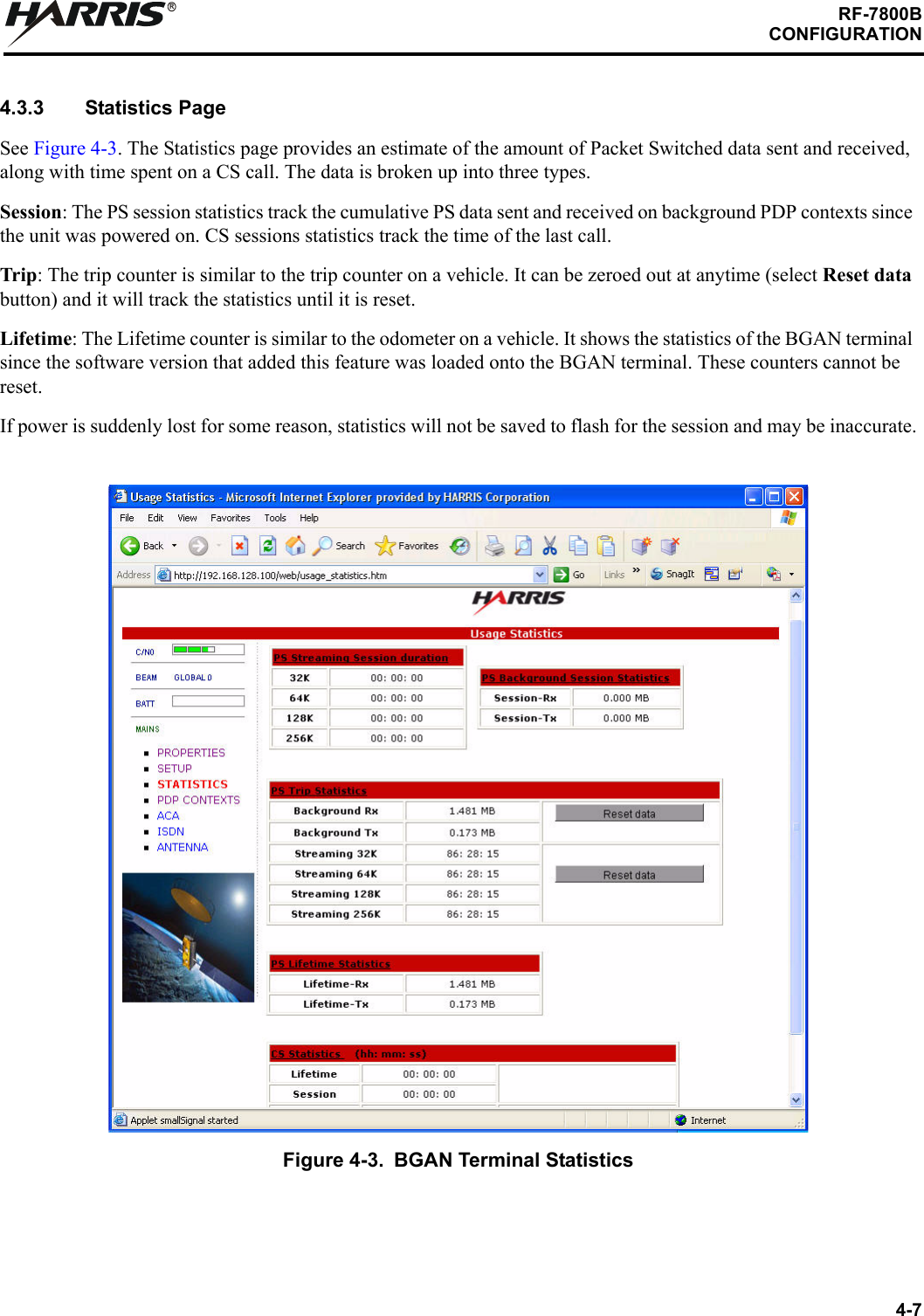
4-7RF-7800BCONFIGURATIONR4.3.3 Statistics PageSee Figure 4-3. The Statistics page provides an estimate of the amount of Packet Switched data sent and received, along with time spent on a CS call. The data is broken up into three types. Session: The PS session statistics track the cumulative PS data sent and received on background PDP contexts since the unit was powered on. CS sessions statistics track the time of the last call.Trip: The trip counter is similar to the trip counter on a vehicle. It can be zeroed out at anytime (select Reset data button) and it will track the statistics until it is reset.Lifetime: The Lifetime counter is similar to the odometer on a vehicle. It shows the statistics of the BGAN terminal since the software version that added this feature was loaded onto the BGAN terminal. These counters cannot be reset.If power is suddenly lost for some reason, statistics will not be saved to flash for the session and may be inaccurate.Figure 4-3. BGAN Terminal Statistics
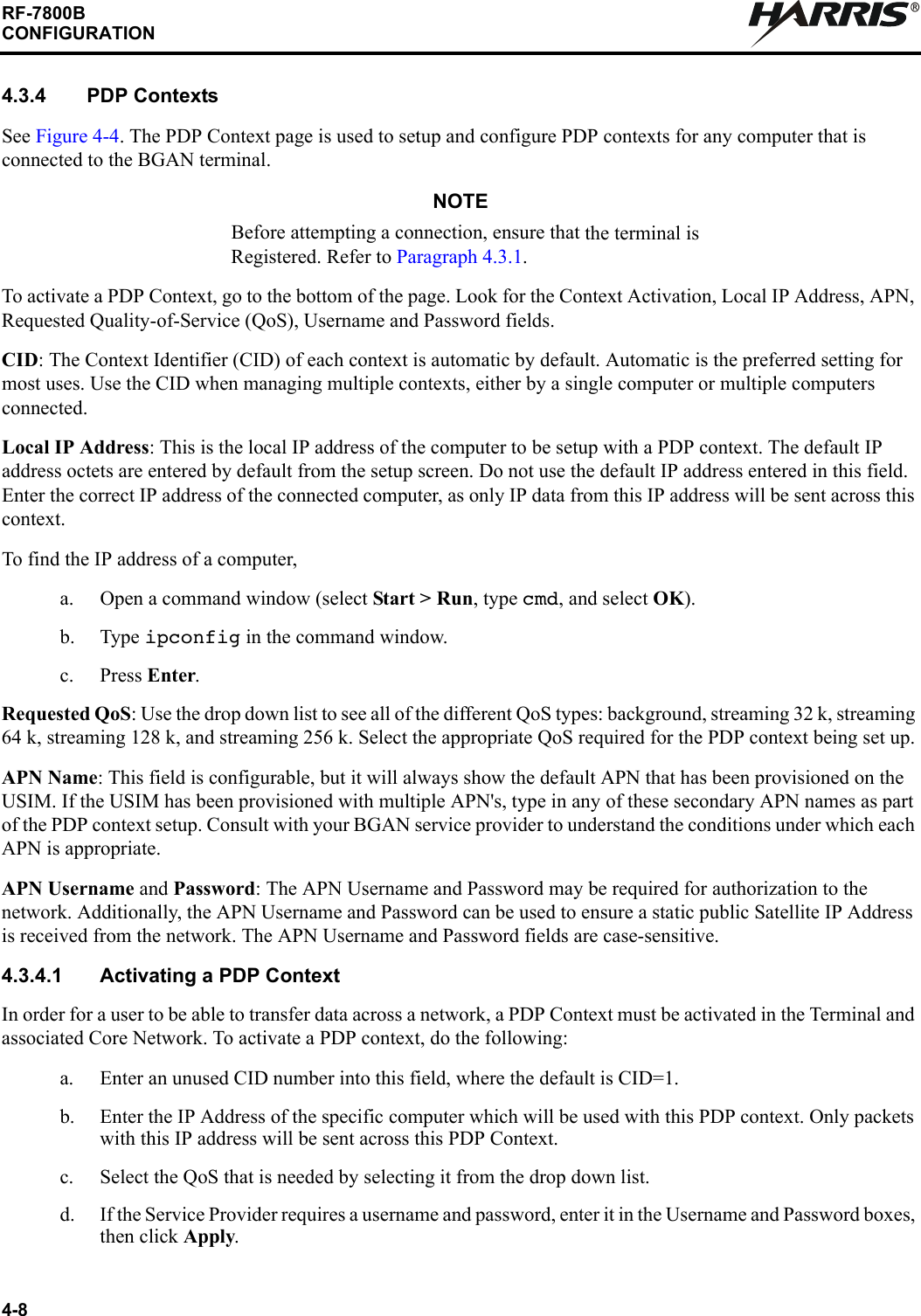
4-8RF-7800BCONFIGURATIONR4.3.4 PDP ContextsSee Figure 4-4. The PDP Context page is used to setup and configure PDP contexts for any computer that is connected to the BGAN terminal. NOTEBefore attempting a connection, ensure that the terminal is Registered. Refer to Paragraph 4.3.1. To activate a PDP Context, go to the bottom of the page. Look for the Context Activation, Local IP Address, APN, Requested Quality-of-Service (QoS), Username and Password fields. CID: The Context Identifier (CID) of each context is automatic by default. Automatic is the preferred setting for most uses. Use the CID when managing multiple contexts, either by a single computer or multiple computers connected.Local IP Address: This is the local IP address of the computer to be setup with a PDP context. The default IP address octets are entered by default from the setup screen. Do not use the default IP address entered in this field. Enter the correct IP address of the connected computer, as only IP data from this IP address will be sent across this context.To find the IP address of a computer, a. Open a command window (select Start > Run, type cmd, and select OK).b. Type ipconfig in the command window.c. Press Enter.Requested QoS: Use the drop down list to see all of the different QoS types: background, streaming 32 k, streaming 64 k, streaming 128 k, and streaming 256 k. Select the appropriate QoS required for the PDP context being set up.APN Name: This field is configurable, but it will always show the default APN that has been provisioned on the USIM. If the USIM has been provisioned with multiple APN's, type in any of these secondary APN names as part of the PDP context setup. Consult with your BGAN service provider to understand the conditions under which each APN is appropriate.APN Username and Password: The APN Username and Password may be required for authorization to the network. Additionally, the APN Username and Password can be used to ensure a static public Satellite IP Address is received from the network. The APN Username and Password fields are case-sensitive.4.3.4.1 Activating a PDP ContextIn order for a user to be able to transfer data across a network, a PDP Context must be activated in the Terminal and associated Core Network. To activate a PDP context, do the following:a. Enter an unused CID number into this field, where the default is CID=1.b. Enter the IP Address of the specific computer which will be used with this PDP context. Only packets with this IP address will be sent across this PDP Context. c. Select the QoS that is needed by selecting it from the drop down list.d. If the Service Provider requires a username and password, enter it in the Username and Password boxes, then click Apply.
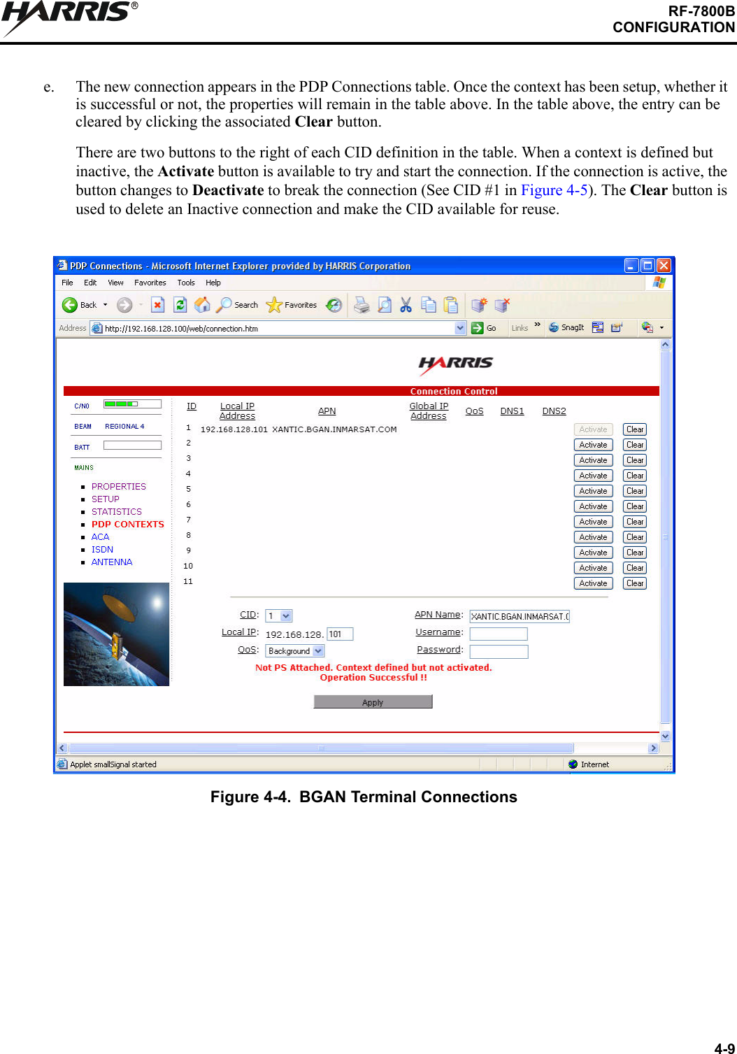
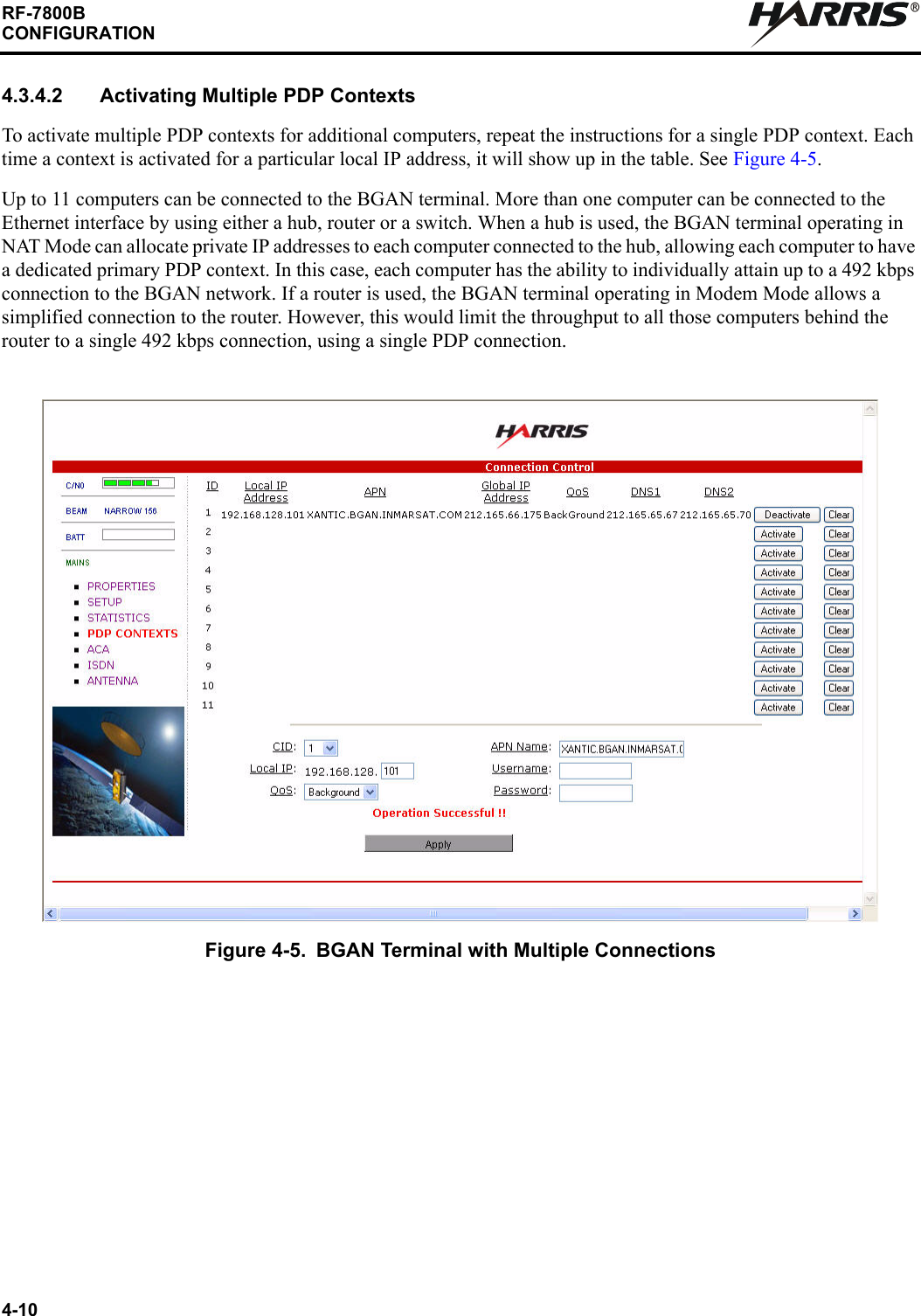
4-9RF-7800BCONFIGURATIONRe. The new connection appears in the PDP Connections table. Once the context has been setup, whether it is successful or not, the properties will remain in the table above. In the table above, the entry can be cleared by clicking the associated Clear button.There are two buttons to the right of each CID definition in the table. When a context is defined but inactive, the Activate button is available to try and start the connection. If the connection is active, the button changes to Deactivate to break the connection (See CID #1 in Figure 4-5). The Clear button is used to delete an Inactive connection and make the CID available for reuse. Figure 4-4. BGAN Terminal Connections
4-10RF-7800BCONFIGURATIONR4.3.4.2 Activating Multiple PDP ContextsTo activate multiple PDP contexts for additional computers, repeat the instructions for a single PDP context. Each time a context is activated for a particular local IP address, it will show up in the table. See Figure 4-5.Up to 11 computers can be connected to the BGAN terminal. More than one computer can be connected to the Ethernet interface by using either a hub, router or a switch. When a hub is used, the BGAN terminal operating in NAT Mode can allocate private IP addresses to each computer connected to the hub, allowing each computer to have a dedicated primary PDP context. In this case, each computer has the ability to individually attain up to a 492 kbps connection to the BGAN network. If a router is used, the BGAN terminal operating in Modem Mode allows a simplified connection to the router. However, this would limit the throughput to all those computers behind the router to a single 492 kbps connection, using a single PDP connection.Figure 4-5. BGAN Terminal with Multiple Connections
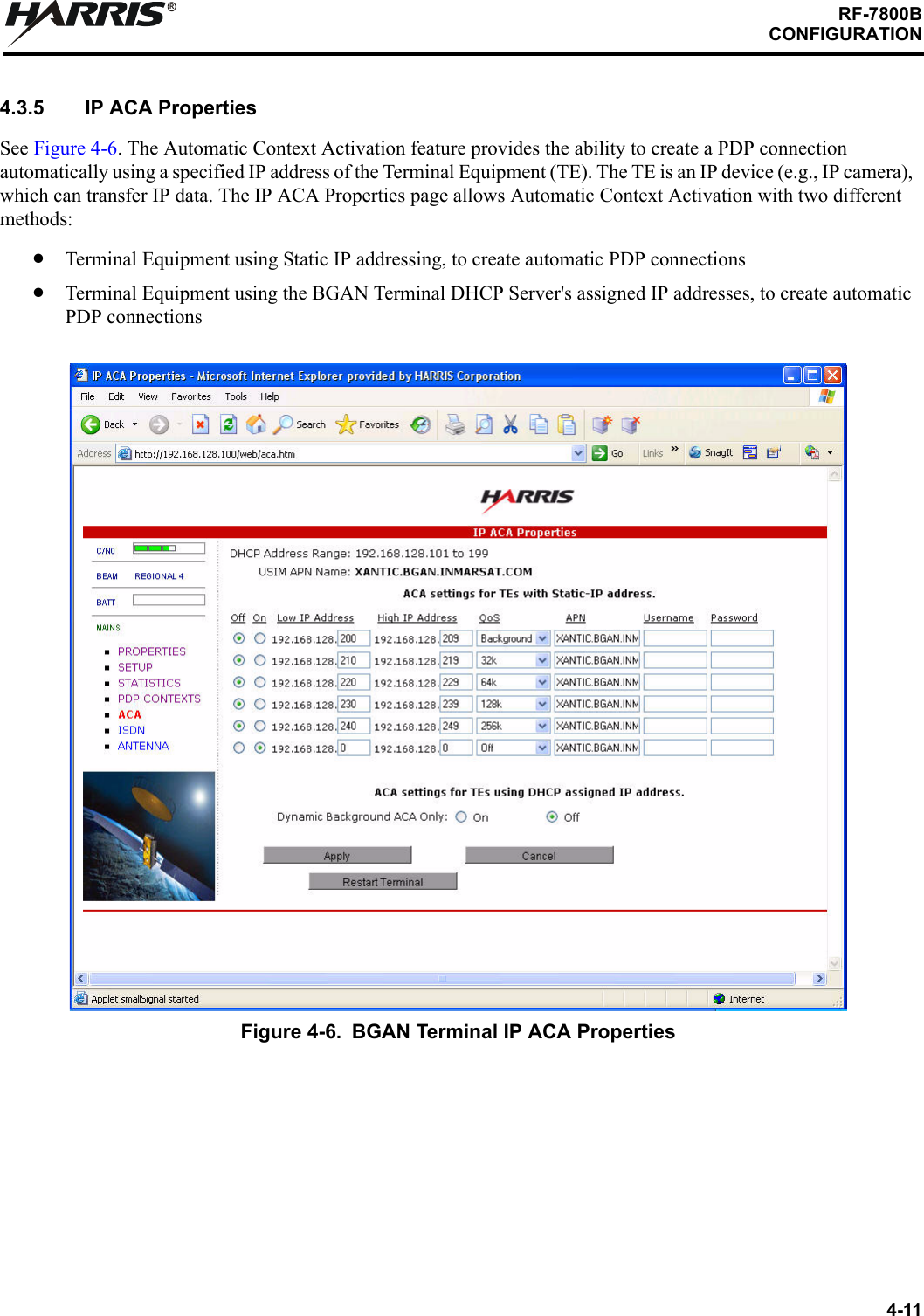
4-11RF-7800BCONFIGURATIONR4.3.5 IP ACA PropertiesSee Figure 4-6. The Automatic Context Activation feature provides the ability to create a PDP connection automatically using a specified IP address of the Terminal Equipment (TE). The TE is an IP device (e.g., IP camera), which can transfer IP data. The IP ACA Properties page allows Automatic Context Activation with two different methods:Terminal Equipment using Static IP addressing, to create automatic PDP connectionsTerminal Equipment using the BGAN Terminal DHCP Server's assigned IP addresses, to create automatic PDP connectionsFigure 4-6. BGAN Terminal IP ACA Properties
4-12RF-7800BCONFIGURATIONR4.3.5.1 ACA settings for TE with Static IP address:A custom range of static IP addresses can be used for setting up an automatic PDP context with any of the QoS's offered by the network. To turn on a particular range of addresses:a. Select On and enter the low and high range of IP addresses to use (e.g. 192.168.128.210 to 192.168.128.219).b. Select the desired QoS for that range of IP addresses (32 k) for streaming. The APN listed is the default APN read from the USIM card (bgan.inmarsat.com). If the USIM is provisioned for more than one APN, then type a secondary APN in this field. c. If a user name and password is required by the Service Provider, enter it in the next two fields.To setup additional ranges of addresses, follow the same instructions as above. IP address ranges cannot overlap. If there is an overlap, an error will pop-up for the overlap region. Check all of the ranges for overlaps and try again.When finished, select Apply. The Operation Successful message should display.4.3.5.2 ACA settings for TE using DHCP assigned IP addressThis option allows the BGAN terminal to be set up for dynamic background ACA. This means that any device connected to the BGAN terminal, will automatically receive a background PDP context. To activate this feature:a. Select the On radio button under ACA settings for TEs using DHCP assigned IP address.b. Click on Apply.To see if the context has been setup properly, click on PDP Contexts page. This page will show all contexts that have been setup (active or inactive). See Figure 4-5.
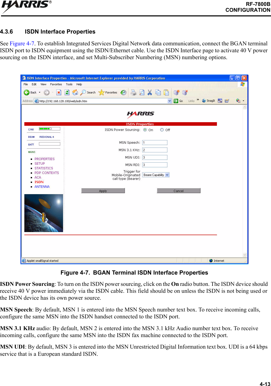
4-13RF-7800BCONFIGURATIONR4.3.6 ISDN Interface PropertiesSee Figure 4-7. To establish Integrated Services Digital Network data communication, connect the BGAN terminal ISDN port to ISDN equipment using the ISDN/Ethernet cable. Use the ISDN Interface page to activate 40 V power sourcing on the ISDN interface, and set Multi-Subscriber Numbering (MSN) numbering options. ISDN Power Sourcing: To turn on the ISDN power sourcing, click on the On radio button. The ISDN device should receive 40 V power immediately via the ISDN cable. This field should be on unless the ISDN is not being used or the ISDN device has its own power source.MSN Speech: By default, MSN 1 is entered into the MSN Speech number text box. To receive incoming calls, configure the same MSN into the ISDN handset connected to the ISDN port.MSN 3.1 KHz audio: By default, MSN 2 is entered into the MSN 3.1 kHz Audio number text box. To receive incoming calls, configure the same MSN into the ISDN fax machine connected to the ISDN port.MSN UDI: By default, MSN 3 is entered into the MSN Unrestricted Digital Information text box. UDI is a 64 kbps service that is a European standard ISDN.Figure 4-7. BGAN Terminal ISDN Interface Properties
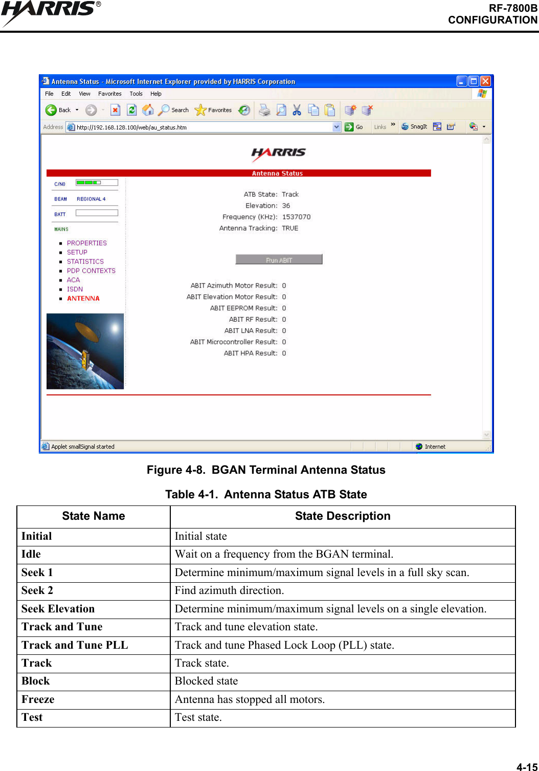
4-14RF-7800BCONFIGURATIONRMSN RDI: By default, MSN 3 is entered into the MSN Restricted Digital Information text box. RDI is a 56 kbps service that is normally found in the USA.Trigger for Mobile-Originated call type (Bearer): This drop down box controls the mechanism used by the BGAN terminal to select the bearer type for mobile originated calls.Bearer Capability is set by default as the trigger.MSN Number can be set if there is a problem and the ISDN device does not correctly signal the call type (speech, 3.1 kHz audio, UDI, RDI) via the bearer capability. Different MSN numbers can be used for any of the ISDN call types. However, the ISDN equipment must be configured with the same MSN to accept incoming calls, and different numbers must be used for speech, audio and UDI/RDI calls.Once all changes have been made, click on Apply. Any changes to this screen require a re-boot of the BGAN terminal to save the new configuration. Use the power button on the BGAN terminal or the Restart Terminal button to gracefully power down and power back up the BGAN terminal.4.3.7 Antenna StatusSee Figure 4-8. The Antenna Status page is only used for the RF-7800B-VU104 tracking antenna. It is used to monitor the status of the antenna. This page does not automatically update and must be refreshed to poll for the latest status.ATB State: This field indicates the detailed state of the Antenna Tracking Board (ATB) and indicates whether the antenna is tracking or searching for the satellite. Refer to Table 4-1.Elevation: The current elevation angle of the antenna.Frequency (KHz): The frequency of the global beam in kHz that the antenna is tracking. Possible values are the primary and secondary frequencies of the three satellites. Refer to Table 4-2.Antenna Tracking: Indicates (TRUE or FALSE) whether or not the antenna is currently tracking the satellite (in states 5, 6 or 7).Run ABIT: Refer to Table 4-3 for Antenna Built-In Test (ABIT) results. No fault is shown as 0. For faults, refer to Paragraph 5.2.1. For any recurring faults, return unit for repair.
4-15RF-7800BCONFIGURATIONRFigure 4-8. BGAN Terminal Antenna StatusTable 4-1. Antenna Status ATB StateState Name State DescriptionInitial Initial stateIdle  Wait on a frequency from the BGAN terminal.Seek 1  Determine minimum/maximum signal levels in a full sky scan.Seek 2  Find azimuth direction.Seek Elevation  Determine minimum/maximum signal levels on a single elevation.Track and Tune  Track and tune elevation state.Track and Tune PLL  Track and tune Phased Lock Loop (PLL) state.Track Track state.Block Blocked stateFreeze  Antenna has stopped all motors.Test Test state.
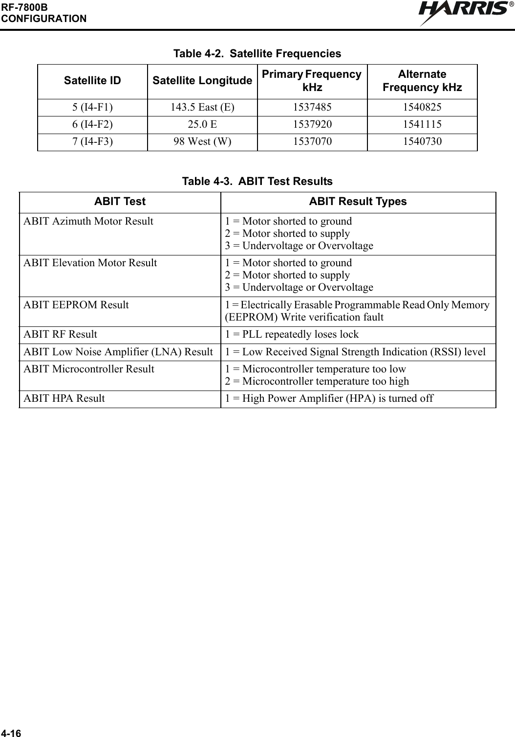
4-16RF-7800BCONFIGURATIONRTable 4-2. Satellite FrequenciesSatellite ID Satellite Longitude Primary Frequency kHzAlternate Frequency kHz5 (I4-F1) 143.5 East (E) 1537485 15408256 (I4-F2) 25.0 E 1537920 15411157 (I4-F3) 98 West (W) 1537070 1540730Table 4-3. ABIT Test ResultsABIT Test ABIT Result TypesABIT Azimuth Motor Result 1 = Motor shorted to ground 2 = Motor shorted to supply3 = Undervoltage or OvervoltageABIT Elevation Motor Result 1 = Motor shorted to ground 2 = Motor shorted to supply3 = Undervoltage or OvervoltageABIT EEPROM Result 1 = Electrically Erasable Programmable Read Only Memory (EEPROM) Write verification faultABIT RF Result 1 = PLL repeatedly loses lockABIT Low Noise Amplifier (LNA) Result 1 = Low Received Signal Strength Indication (RSSI) levelABIT Microcontroller Result 1 = Microcontroller temperature too low2 = Microcontroller temperature too highABIT HPA Result 1 = High Power Amplifier (HPA) is turned off

Navigation menu