Harris RF Communications Division XG-100LPA XG-100LPA Low Band Power Amplifier User Manual
Harris Corporation RF Communications Division XG-100LPA Low Band Power Amplifier
UserManual.wiki
>
Harris RF Communications Division
>
XG 100LPA User Manual
User Manual
Navigation menu
Upload a User Manual
Namespaces
Wiki Guide
HTML
PDF
Info
Views
User Manual
Discussion / Help
Navigation

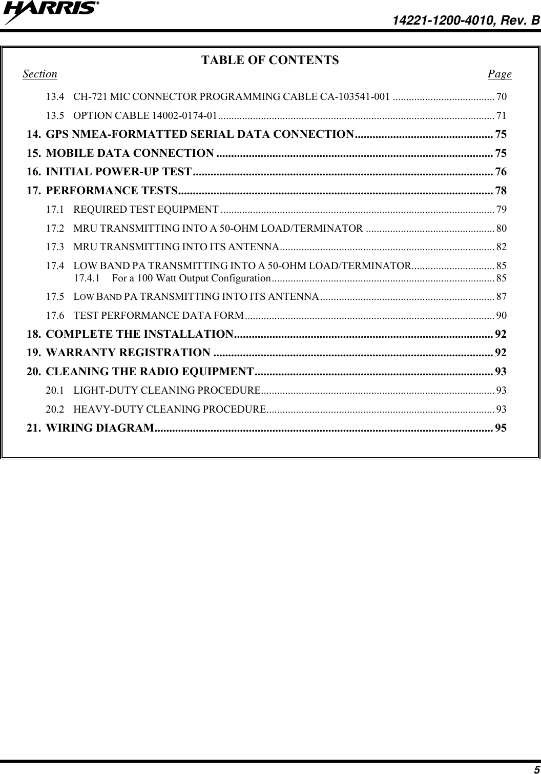
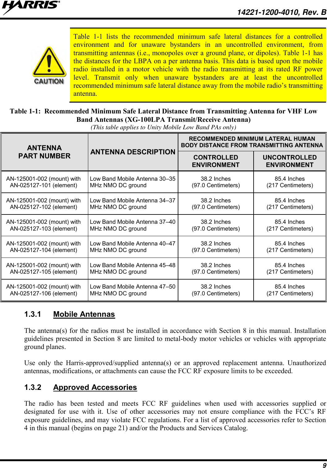
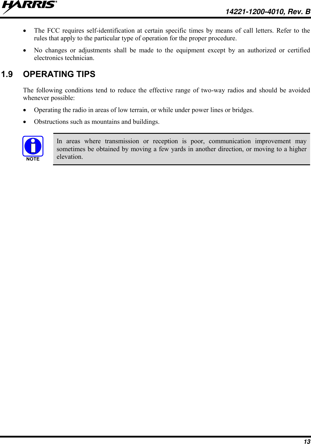
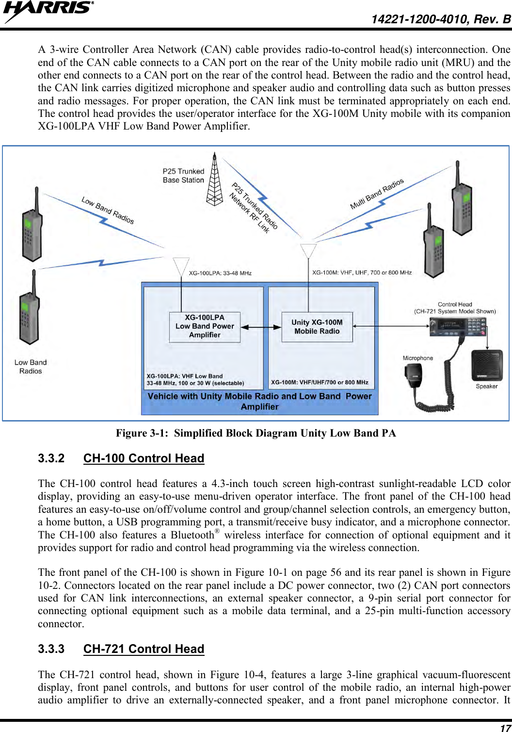
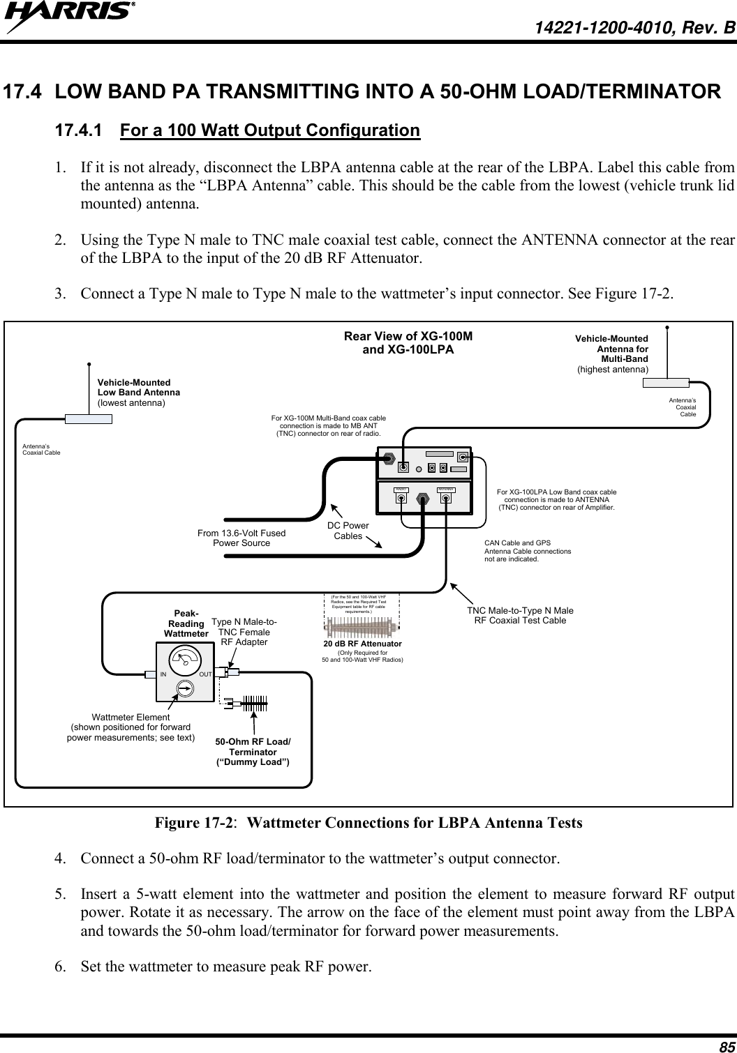
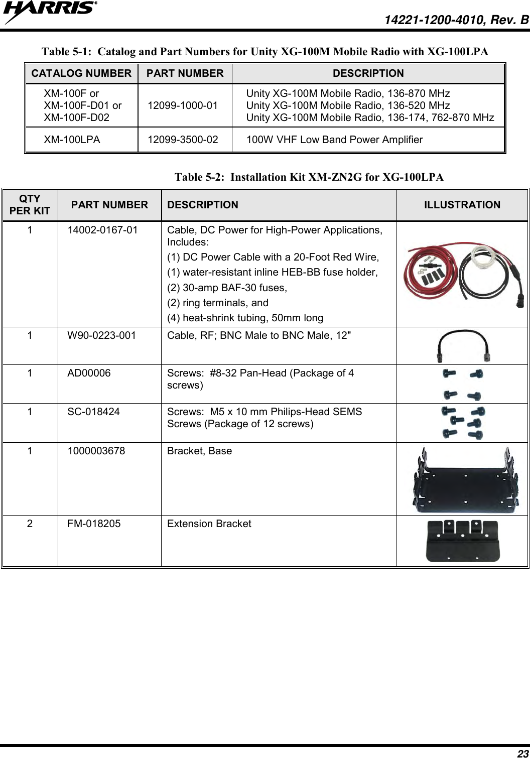
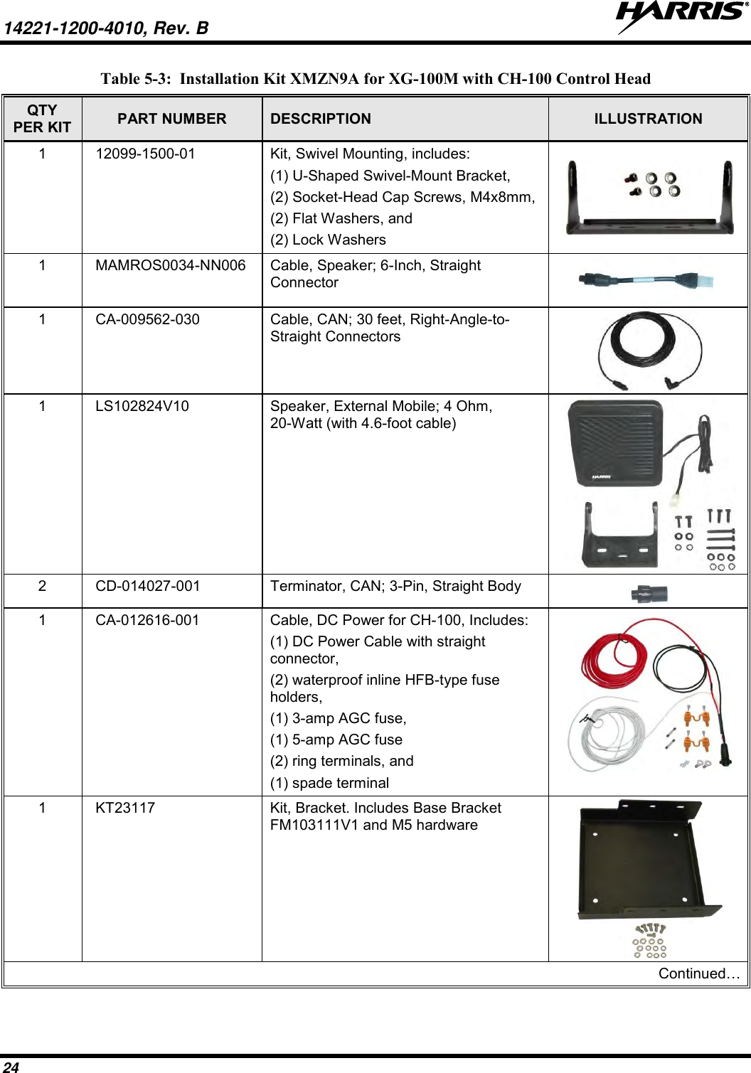
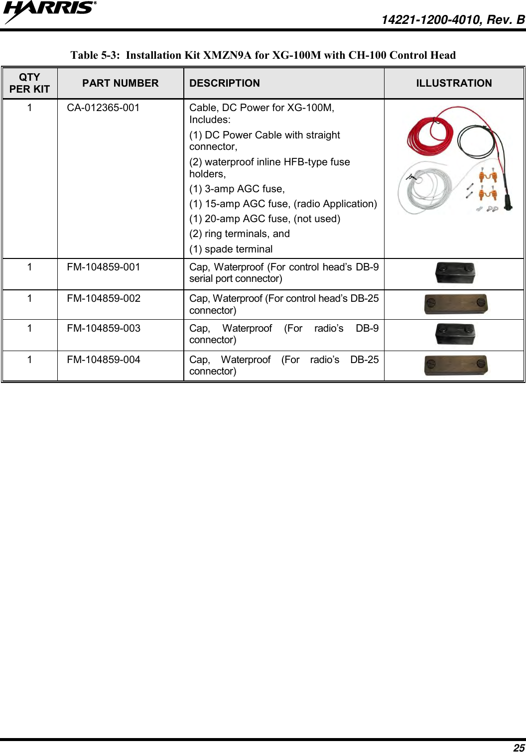
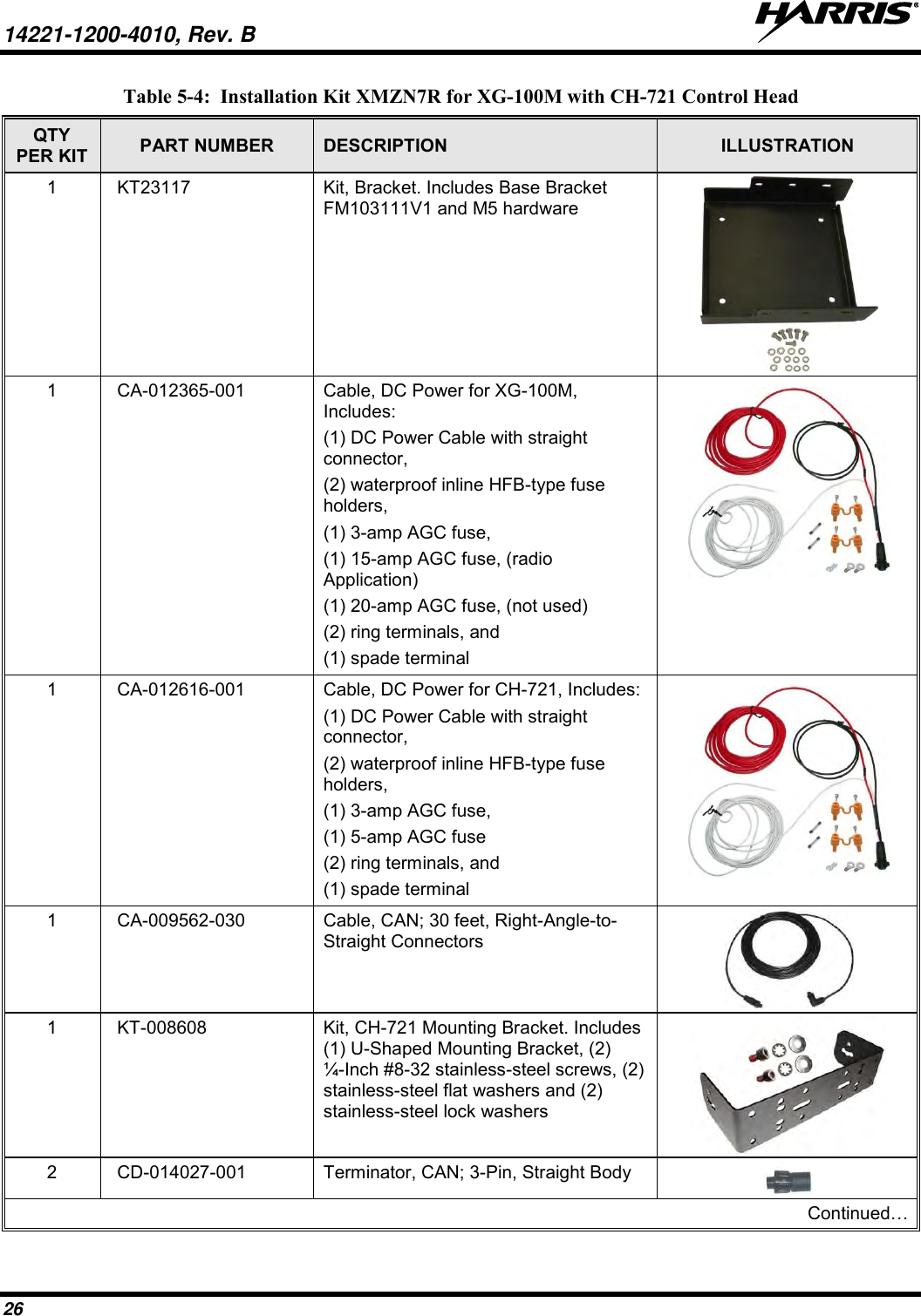
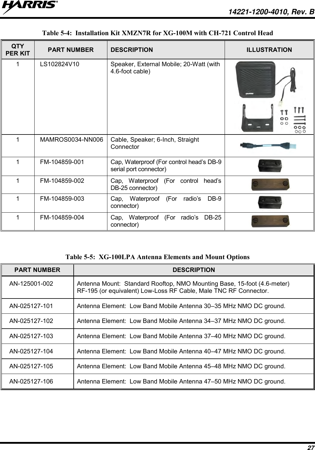
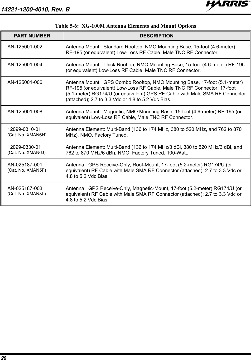
![14221-1200-4010, Rev. B 22 5. UNPACKING AND CHECKING THE EQUIPMENT Upon receipt of the Harris equipment, carefully unpack the equipment and verify that the order is complete. Inspect the equipment for any shipping damage. If there is any damage to the equipment, contact the carrier immediately and have their representative verify the damage. If you fail to report the shipping damage immediately, you may forfeit any claim against the carrier. When unpacking the equipment, check the contents against the packing list. Contact your Harris representative and the carrier if any discrepancies are noted. After verifying all equipment is accounted for, proceed with the installation. After removal from the carton, examine the mobile radios, control head, and other components for broken, damaged, loose, or missing parts. If any are noted, contact the Customer Care center (see page 21) immediately to discuss and arrange the return of the equipment to Harris for replacement. Any unauthorized attempts to repair or modify this equipment will void the warranty and could create a safety hazard. 5.1 MATERIALS A typical set of installation materials for a Unity XG-100M mobile radio with XG-100LPA VHF Low Band Amplifier includes: Unity XG-100M Mobile Radio -refer to Table 5-1. Unity XG-100LPA 100W Low Band Power Amplifier -refer to Table 5-1. CH-100 Control Head [12099-1200-01; catalog number XMCP9R]. or CH-721 System Control Head [part number CU23218-0004; catalog number MAMW-NCP9F]. Standard Microphone [part number MC-101616-041; part of catalog number MAMW-NMC7Z]. Installation Kits: Unity XG-100LPA – contents listed in Table 5-2. XG-100M with Remote CH-100 Control head - contents listed in Table 5-3. XG-100M with Remote CH-721 System Control head - contents listed in Table 5-4. Two (2) or Three (3) Antennas - refer to Table 5-5 for VHF Low Band antennas and Table 5-6 for other XG-100M antenna options.](https://usermanual.wiki/Harris-RF-Communications-Division/XG-100LPA/User-Guide-2526336-Page-23.png)
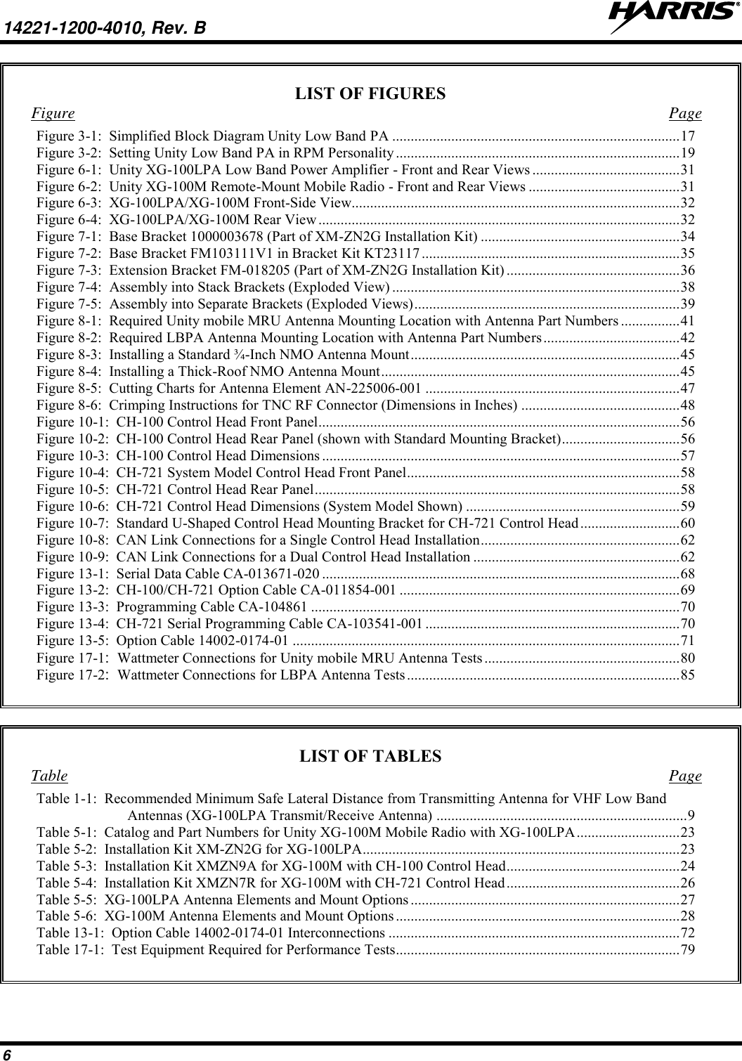
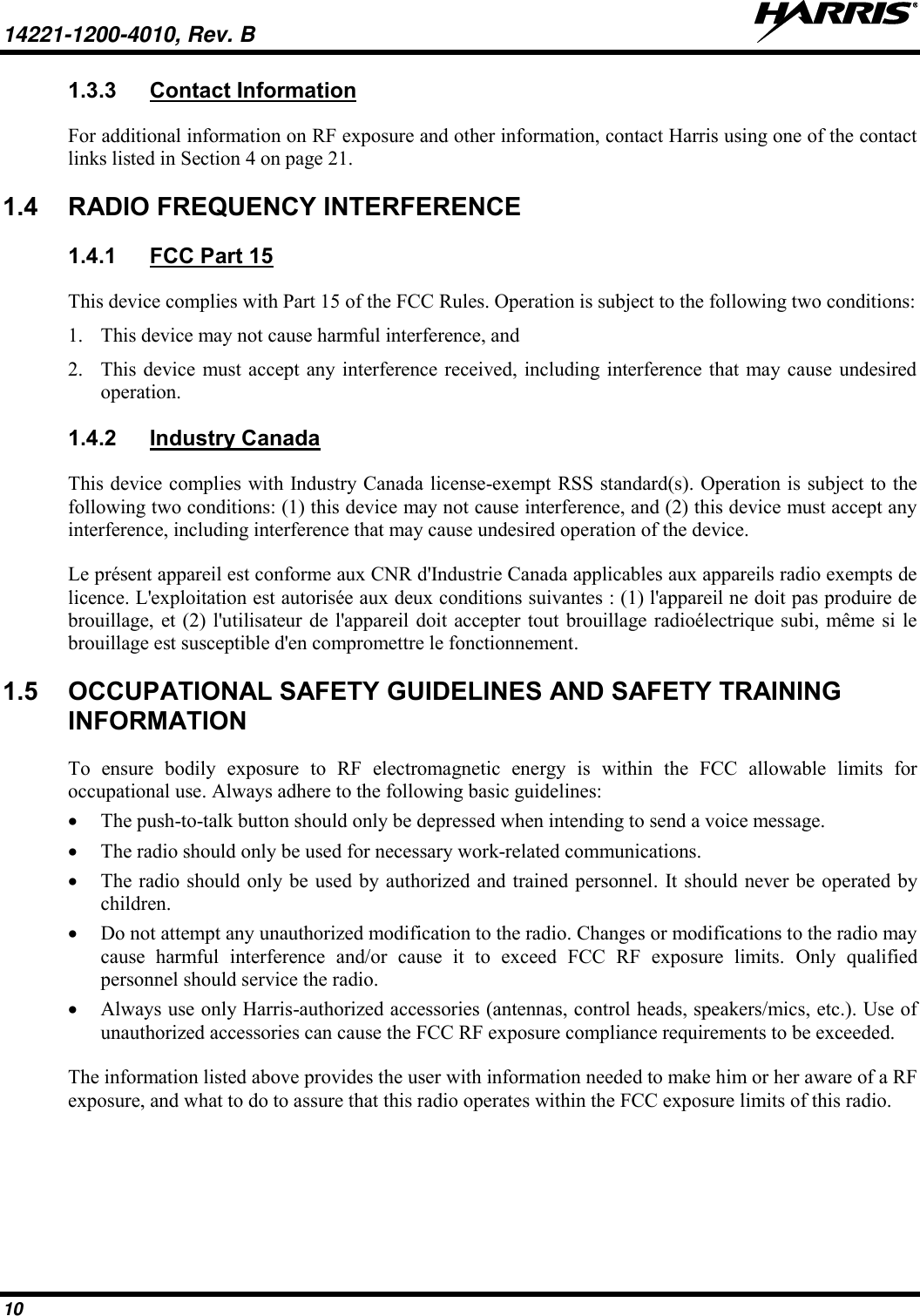
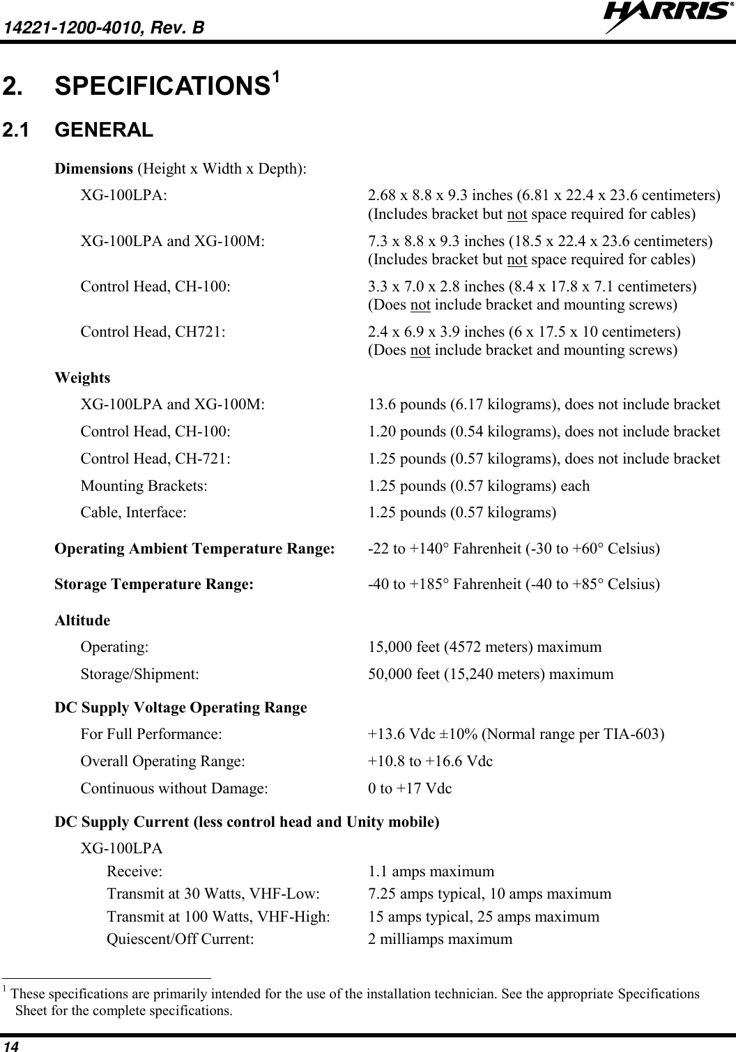
![14221-1200-4010, Rev. B 67 11. SPEAKER INSTALLATION Select a location for the speaker that will allow for proper listening range with a moderate volume setting. Total speaker cable length (of both cables) is approximately five (5) feet. Therefore, to include service loops in the cables, the speaker must be mounted within approximately 4.5 feet of the control head. 1. Install the speaker LS102824V10 in Table 5-3 (CH-100) or Table 5-4 (CH-721) using the hardware and mounting bracket supplied with it. Also refer to the instructions included in the speaker for additional mechanical installation information. 2. Route the speaker’s cable to the rear of the control head. 3. Mate the Speaker Cable MAMROS0034-NN006 [Table 5-3 (CH-100) or Table 5-4 (CH-721)] to the 2-pin “AUDIO” connector at the rear of the control head by visually aligning the ¾-moon-shaped keys of the connectors. Push and turn the outer locking ring of the cable connector clockwise until it stops. A mild click will be sensed to confirm proper mating. 4. Connect the speaker’s 2-pin plastic connector to the respective mating connector on the Speaker’s cable. 5. Route the cables out of the way of casual contact and tie and stow as necessary. 12. MICROPHONE ATTACHMENT There are several versions of microphones available for use with the CH-100 and CH-721 control heads. Each microphone has a 17-pin flush-mount type connector that mates with the microphone (“mic”) connector on the front panel of the control head. The mic’s connector includes a captive thumbscrew that secures it to the mic connector on the front panel of the control head. A microphone clip is included with each microphone. The radio can be configured to provide a monitor function when the microphone is cradled in the clip. Connect the mic to the control head and install the clip as follows: 1. Grasp the mic’s connector with a thumb and index finger on the sides of the connector just adjacent to the thumbscrew. 2. Position connector just in front of the control head’s mic connector so its male pins can engage straight into the female (socket) pins of the control head’s mic connector. The thumbscrew must be oriented directly below the hanging mic cable. 3. Mate the two connectors by pressing them fully together. Do not apply any force to the thumbscrew when mating the connectors. 4. Tighten the thumbscrew finger-tight. Do not use a screwdriver to tighten it. 5. Using the microphone clip as a template, drill mounting holes in the surface of the selected location. 6. Select a mounting surface location that has clearance for the mic when it is clipped to the clip, and then attach the microphone clip to the surface. Use self-locking hardware (i.e., machine screws with washers and locking nuts), self-drilling screws, or other appropriate hardware as necessary. Tighten securely. Microphones used with the CH-100 and CH-721 control heads have integrated hookswitches. Therefore, the microphone clip does not need to be grounded. 7. Clip the microphone to the clip.](https://usermanual.wiki/Harris-RF-Communications-Division/XG-100LPA/User-Guide-2526336-Page-68.png)