Harris RF Communications Division XG-100LPA XG-100LPA Low Band Power Amplifier User Manual
Harris Corporation RF Communications Division XG-100LPA Low Band Power Amplifier
User Manual

Rhein Tech Laboratories, Inc. Client: Harris Corporation
360 Herndon Parkway Model: XG-100LPA
Suite 1400 IDs: AQZ-XG-100LPA /122D-XG100LPA
Herndon, VA 20170 Standards: FCC Part 90/ICRSS-119
http://www.rheintech.com Report #: 2014152
35 of 49
Appendix N: Manuals
Please refer to the following pages for the Installation Manual and the Product Safety Manual.

Installation Manual
14221-1200-4010
Rev. B, Jan/15
Unity® Mobile
VHF Low Band Amplifier
XG-100LPA
14221-1200-4010, Rev. B
2
MANUAL REVISION HISTORY
REV.
DATE
REASON FOR CHANGE
-
Nov/14
Initial Release.
A
Jan/15
Changed RF cable part from W90-0223-003 to W90-0223-001 and corrected antenna
element part numbers.
B
Jan/15
Corrected Industry Canada Standard reference and deleted AN-025127-100 antenna
option.
Harris Corporation, Public Safety and Professional Communications (PSPC) Business, continually evaluates its technical
publications for completeness, technical accuracy, and organization. You can assist in this process by submitting your
comments and suggestions to the following:
Harris Corporation fax your comments to: 1-434-455-6851
PSPC Business or
Technical Publications e-mail us at: PSPC_TechPubs@harris.com
221 Jefferson Ridge Parkway
Lynchburg, VA 24501
ACKNOWLEDGEMENT
This device is made under license under one or more of the following US patents: 4,590,473; 4,636,791; 5,148,482;
5,185,796; 5,271,017; 5,377,229; 4,716,407; 4,972,460; 5,502,767; 5,146,497; 5,164,986; 5,185,795; 5,226,084; 5,247,579;
5,491,772; 5,517,511; 5,630,011; 5,649,050; 5,701,390; 5,715,365; 5,754,974; 5,826,222; 5,870,405; 6,161,089; and
6,199,037 B1. DVSI claims certain rights, including patent rights under aforementioned U.S. patents, and under other U.S.
and foreign patents and patents pending. Any use of this software or technology requires a separate written license from
DVSI.
CREDITS
Harris, assured communications, and Unity are registered trademarks of Harris Corporation.
All other brand and product names are trademarks, registered trademarks, or service marks of their respective holders.
NOTICE!
The material contained herein is subject to U.S. export approval. No export or re-export is permitted without written approval
from the U.S. Government. Rated: EAR99 in accordance with U.S. Dept. of Commerce regulations 15CFR774, Export
Administration Regulations.
Information and descriptions contained herein are the property of Harris Corporation. Such information and descriptions may
not be copied or reproduced by any means, or disseminated or distributed without the express prior written permission of
Harris Corporation, PSPC Business, 221 Jefferson Ridge Parkway, Lynchburg, VA 24501.
Repairs to this equipment should be made only by an authorized service technician or facility designated by the supplier. Any
repairs, alterations, or substitutions of recommended parts made by the user to this equipment not approved by the
manufacturer could void the user's authority to operate the equipment in addition to the manufacturer's warranty.
This product conforms to the European Union WEEE Directive 2012/19/EU. Do not dispose of this product in a
public landfill. Take it to a recycling center at the end of its life.
This manual is published by Harris Corporation without any warranty. Improvements and changes to this manual
necessitated by typographical errors, inaccuracies of current information, or improvements to programs and/or equipment,
may be made by Harris Corporation at any time and without notice. Such changes will be incorporated into new editions of
this manual. No part of this manual may be reproduced or transmitted in any form or by any means, electronic or mechanical,
including photocopying and recording, for any purpose, without the express written permission of Harris Corporation.
Copyright© 2014, 2015 Harris Corporation

14221-1200-4010, Rev. B
3
TABLE OF CONTENTS
Section Page
1. REGULATORY AND SAFETY INFORMATION .................................................................... 7
1.1 SAFETY SYMBOL CONVENTIONS ................................................................................................. 7
1.2 RF ENERGY EXPOSURE AWARENESS AND CONTROL INFORMATION FOR FCC
OCCUPATIONAL USE REQUIREMENTS ........................................................................................ 7
1.2.1 Federal Communications Commission Regulations ............................................................... 8
1.3 COMPLIANCE WITH RF EXPOSURE STANDARDS ...................................................................... 8
1.3.1 Mobile Antennas .................................................................................................................... 9
1.3.2 Approved Accessories ............................................................................................................ 9
1.3.3 Contact Information .............................................................................................................. 10
1.4 RADIO FREQUENCY INTERFERENCE ......................................................................................... 10
1.4.1 FCC Part 15 .......................................................................................................................... 10
1.4.2 Industry Canada .................................................................................................................... 10
1.5 OCCUPATIONAL SAFETY GUIDELINES AND SAFETY TRAINING INFORMATION............ 10
1.6 COMMON HAZARDS ...................................................................................................................... 11
1.7 SAFE DRIVING RECOMMENDATIONS ........................................................................................ 12
1.8 OPERATING RULES REGULATIONS ............................................................................................ 12
1.9 OPERATING TIPS ............................................................................................................................. 13
2. SPECIFICATIONS ...................................................................................................................... 14
2.1 GENERAL .......................................................................................................................................... 14
2.2 TRANSMITTER ................................................................................................................................ 15
2.3 REGULATORY ................................................................................................................................. 15
3. INTRODUCTION ........................................................................................................................ 16
3.1 GENERAL INFORMATION ............................................................................................................. 16
3.2 EQUIPMENT MOUNTING ............................................................................................................... 16
3.3 CONTROL HEADS ........................................................................................................................... 16
3.3.1 General Information ............................................................................................................. 16
3.3.2 CH-100 Control Head ........................................................................................................... 17
3.3.3 CH-721 Control Head ........................................................................................................... 17
3.4 OPERATING POWER ....................................................................................................................... 18
3.5 RADIO PROGRAMMING ................................................................................................................. 18
3.6 RELATED PUBLICATIONS ............................................................................................................. 20
4. CUSTOMER SERVICE .............................................................................................................. 21
4.1 TECHNICAL SUPPORT.................................................................................................................... 21
4.2 TECH-LINK ....................................................................................................................................... 21
4.3 CUSTOMER CARE ........................................................................................................................... 21
5. UNPACKING AND CHECKING THE EQUIPMENT ........................................................... 22
5.1 MATERIALS...................................................................................................................................... 22
6. PLANNING THE INSTALLATION ......................................................................................... 29

14221-1200-4010, Rev. B
4
TABLE OF CONTENTS
Section Page
6.1 GENERAL INFORMATION ............................................................................................................. 29
6.2 TOOLS REQUIRED ........................................................................................................................... 29
6.3 LOCATING COMPONENTS............................................................................................................. 30
7. MOUNTING THE RADIO EQUIPMENT ............................................................................... 33
7.1 INSTALL THE MOUNTING BRACKETS ........................................................................................ 33
7.2 MOUNT THE EQUIPMENT INTO THE BRACKETS ..................................................................... 37
7.2.1 MRU and LBPA Mounting ................................................................................................... 37
8. ANTENNA INSTALLATION .................................................................................................... 40
8.1 ANTENNA MOUNTING LOCATIONS ............................................................................................ 40
8.1.1 Direct Center or Center-Rear of Rooftop for MRU Antenna ................................................ 40
8.1.2 Center of Trunk Lid for LBPA Antenna ............................................................................... 40
8.1.3 Rear Deck Lid for GPS Stand-Alone GPS Receive Antenna ............................................... 42
8.2 ANTENNA INSTALLATION PROCEDURES ................................................................................. 43
8.2.1 Installing NMO Antenna Mounts AN-125001-001, -002, -003 and -004 ............................. 43
8.2.2 Installing NMO Magnetic Antenna Mounts AN-125001-007 and -008 ............................... 46
8.2.3 Installing all Other Antenna Mounts ..................................................................................... 46
8.2.4 Attaching NMO Antenna Elements ...................................................................................... 46
8.2.5 Connecting the Mobile Antennas .......................................................................................... 48
8.2.6 Connect RF Cable between Unity Mobile MRU and Low Band PA .................................... 49
9. DC POWER INSTALLATION .................................................................................................. 50
9.1 OVERVIEW OF ON/OFF POWER WIRING CONFIGURATIONS ................................................. 50
9.2 POWER INSTALLATION PROCEDURE ......................................................................................... 51
9.2.1 Radios DC Power Cables and Main Fuse Holders Installation ............................................. 51
10. CONTROL HEAD INSTALLATION ....................................................................................... 55
10.1 SELECTING THE MOUNTING LOCATION ................................................................................... 55
10.2 GENERAL INFORMATION ON THE CH-100 CONTROL HEAD ................................................. 56
10.3 GENERAL INFORMATION ON THE CH-721 CONTROL HEAD ................................................. 58
10.4 CONTROL HEAD MECHANICAL INSTALLATION ..................................................................... 60
10.5 CONTROL HEAD-TO-RADIO CAN CABLE CONNECTIONS ...................................................... 61
10.5.1 General Information .............................................................................................................. 61
10.5.2 Make CAN Link Terminations and Cable Connection ......................................................... 63
10.6 CONTROL HEAD POWER CABLE INSTALLATION .................................................................... 63
10.6.1 Install DC Power Cable and Make Power and Ground Connections .................................... 64
10.6.2 Connect DC Power Cable’s White Wire ............................................................................... 65
11. SPEAKER INSTALLATION ..................................................................................................... 67
12. MICROPHONE ATTACHMENT ............................................................................................. 67
13. OPTIONAL CABLES ................................................................................................................. 68
13.1 SERIAL PROGRAMMING CABLE CA-013671-020 ....................................................................... 68
13.2 CH-100/CH-721 OPTION CABLE CA-011854-001 .......................................................................... 69
13.3 CH-721 SERIAL PROGRAMMING CABLE CA-104861 ................................................................. 70

14221-1200-4010, Rev. B
5
TABLE OF CONTENTS
Section Page
13.4 CH-721 MIC CONNECTOR PROGRAMMING CABLE CA-103541-001 ...................................... 70
13.5 OPTION CABLE 14002-0174-01 ....................................................................................................... 71
14. GPS NMEA-FORMATTED SERIAL DATA CONNECTION ............................................... 75
15. MOBILE DATA CONNECTION .............................................................................................. 75
16. INITIAL POWER-UP TEST ...................................................................................................... 76
17. PERFORMANCE TESTS ........................................................................................................... 78
17.1 REQUIRED TEST EQUIPMENT ...................................................................................................... 79
17.2 MRU TRANSMITTING INTO A 50-OHM LOAD/TERMINATOR ................................................ 80
17.3 MRU TRANSMITTING INTO ITS ANTENNA ................................................................................ 82
17.4 LOW BAND PA TRANSMITTING INTO A 50-OHM LOAD/TERMINATOR............................... 85
17.4.1 For a 100 Watt Output Configuration ................................................................................... 85
17.5 LOW BAND PA TRANSMITTING INTO ITS ANTENNA ................................................................. 87
17.6 TEST PERFORMANCE DATA FORM ............................................................................................. 90
18. COMPLETE THE INSTALLATION ........................................................................................ 92
19. WARRANTY REGISTRATION ............................................................................................... 92
20. CLEANING THE RADIO EQUIPMENT ................................................................................. 93
20.1 LIGHT-DUTY CLEANING PROCEDURE....................................................................................... 93
20.2 HEAVY-DUTY CLEANING PROCEDURE ..................................................................................... 93
21. WIRING DIAGRAM ................................................................................................................... 95
14221-1200-4010, Rev. B
6
LIST OF FIGURES
Figure Page
Figure 3-1: Simplified Block Diagram Unity Low Band PA .............................................................................. 17
Figure 3-2: Setting Unity Low Band PA in RPM Personality ............................................................................. 19
Figure 6-1: Unity XG-100LPA Low Band Power Amplifier - Front and Rear Views ........................................ 31
Figure 6-2: Unity XG-100M Remote-Mount Mobile Radio - Front and Rear Views ......................................... 31
Figure 6-3: XG-100LPA/XG-100M Front-Side View......................................................................................... 32
Figure 6-4: XG-100LPA/XG-100M Rear View .................................................................................................. 32
Figure 7-1: Base Bracket 1000003678 (Part of XM-ZN2G Installation Kit) ...................................................... 34
Figure 7-2: Base Bracket FM103111V1 in Bracket Kit KT23117 ...................................................................... 35
Figure 7-3: Extension Bracket FM-018205 (Part of XM-ZN2G Installation Kit) ............................................... 36
Figure 7-4: Assembly into Stack Brackets (Exploded View) .............................................................................. 38
Figure 7-5: Assembly into Separate Brackets (Exploded Views) ........................................................................ 39
Figure 8-1: Required Unity mobile MRU Antenna Mounting Location with Antenna Part Numbers ................ 41
Figure 8-2: Required LBPA Antenna Mounting Location with Antenna Part Numbers ..................................... 42
Figure 8-3: Installing a Standard ¾-Inch NMO Antenna Mount ......................................................................... 45
Figure 8-4: Installing a Thick-Roof NMO Antenna Mount ................................................................................. 45
Figure 8-5: Cutting Charts for Antenna Element AN-225006-001 ..................................................................... 47
Figure 8-6: Crimping Instructions for TNC RF Connector (Dimensions in Inches) ........................................... 48
Figure 10-1: CH-100 Control Head Front Panel .................................................................................................. 56
Figure 10-2: CH-100 Control Head Rear Panel (shown with Standard Mounting Bracket)................................ 56
Figure 10-3: CH-100 Control Head Dimensions ................................................................................................. 57
Figure 10-4: CH-721 System Model Control Head Front Panel.......................................................................... 58
Figure 10-5: CH-721 Control Head Rear Panel ................................................................................................... 58
Figure 10-6: CH-721 Control Head Dimensions (System Model Shown) .......................................................... 59
Figure 10-7: Standard U-Shaped Control Head Mounting Bracket for CH-721 Control Head ........................... 60
Figure 10-8: CAN Link Connections for a Single Control Head Installation ...................................................... 62
Figure 10-9: CAN Link Connections for a Dual Control Head Installation ........................................................ 62
Figure 13-1: Serial Data Cable CA-013671-020 ................................................................................................. 68
Figure 13-2: CH-100/CH-721 Option Cable CA-011854-001 ............................................................................ 69
Figure 13-3: Programming Cable CA-104861 .................................................................................................... 70
Figure 13-4: CH-721 Serial Programming Cable CA-103541-001 ..................................................................... 70
Figure 13-5: Option Cable 14002-0174-01 ......................................................................................................... 71
Figure 17-1: Wattmeter Connections for Unity mobile MRU Antenna Tests ..................................................... 80
Figure 17-2: Wattmeter Connections for LBPA Antenna Tests .......................................................................... 85
LIST OF TABLES
Table Page
Table 1-1: Recommended Minimum Safe Lateral Distance from Transmitting Antenna for VHF Low Band
Antennas (XG-100LPA Transmit/Receive Antenna) .................................................................... 9
Table 5-1: Catalog and Part Numbers for Unity XG-100M Mobile Radio with XG-100LPA ............................ 23
Table 5-2: Installation Kit XM-ZN2G for XG-100LPA ...................................................................................... 23
Table 5-3: Installation Kit XMZN9A for XG-100M with CH-100 Control Head ............................................... 24
Table 5-4: Installation Kit XMZN7R for XG-100M with CH-721 Control Head ............................................... 26
Table 5-5: XG-100LPA Antenna Elements and Mount Options ......................................................................... 27
Table 5-6: XG-100M Antenna Elements and Mount Options ............................................................................. 28
Table 13-1: Option Cable 14002-0174-01 Interconnections ............................................................................... 72
Table 17-1: Test Equipment Required for Performance Tests............................................................................. 79
14221-1200-4010, Rev. B
7
1. REGULATORY AND SAFETY INFORMATION
1.1 SAFETY SYMBOL CONVENTIONS
The following conventions are used in this manual to alert the user to general safety precautions that must
be observed during all phases of operation, service, and repair of this product. Failure to comply with
these precautions or with specific warnings elsewhere violates safety standards of design, manufacture,
and intended use of the product. Harris® assumes no liability for the customer's failure to comply with
these standards.
The WARNING symbol calls attention to a procedure, practice, or the like, which, if
not correctly performed or adhered to, could result in personal injury. Do not proceed
beyond a WARNING symbol until the conditions identified are fully understood or
met.
The CAUTION symbol calls attention to an operating procedure, practice, or the like,
which, if not performed correctly or adhered to, could result in damage to the equipment or
severely degrade equipment performance.
NOTE
The NOTE symbol calls attention to supplemental information, which may improve system
performance or clarify a process or procedure.
1.2 RF ENERGY EXPOSURE AWARENESS AND CONTROL
INFORMATION FOR FCC OCCUPATIONAL USE REQUIREMENTS
Before using the mobile two-way radio, read this important RF energy awareness and control
information to ensure compliance with RF exposure guidelines.
This radio is intended for use in occupational/controlled conditions, where users have
full knowledge of their exposure and can exercise control over their exposure to
remain below RF exposure limits. This radio is NOT authorized for general
population, consumer, or any other use.
Changes or modifications not expressly approved by Harris could void the user's authority
to operate the equipment.
This two-way radio uses electromagnetic energy in the radio frequency (RF) spectrum to provide
communications between two or more users over a distance. It uses RF energy or radio waves to send and
receive calls. RF energy is one form of electromagnetic energy. Other forms include, but are not limited
to, electric power, sunlight, and x-rays. RF energy, however, should not be confused with these other

14221-1200-4010, Rev. B
8
forms of electromagnetic energy, which, when used improperly, can cause biological damage. Very high
levels of x-rays, for example, can damage tissues and genetic material.
Experts in science, engineering, medicine, health, and industry work with organizations to develop
standards for exposure to RF energy. These standards provide recommended levels of RF exposure for
both workers and the general public. These recommended RF exposure levels include substantial margins
of protection. All two-way radios marketed in North America are designed, manufactured, and tested to
ensure they meet government-established RF exposure levels. In addition, manufacturers also recommend
specific operating instructions to users of two-way radios. These instructions are important because they
inform users about RF energy exposure and provide simple procedures on how to control it. Please refer
to the following websites for more information on what RF energy exposure is and how to control
exposure to assure compliance with established RF exposure limits:
http://www.fcc.gov/oet/rfsafety/rf-faqs.html
http://www.osha.gov./SLTC/radiofrequencyradiation/index.html
1.2.1 Federal Communications Commission Regulations
Before it was marketed in the United States, the Unity® mobile Low Band P Power Amplifier (LPA) was
tested to ensure compliance with FCC RF energy exposure limits for mobile two-way radios. When two-
way radios are used as a consequence of employment, the FCC requires users to be fully aware of and
able to control their exposure to meet occupational requirements. Exposure awareness can be facilitated
by the use of a label directing users to specific user awareness information. The radio has an RF exposure
product label. Also, this Installation, the Product Safety Manual, and the applicable Operator’s Manual
include information and operating instructions required to control RF exposure and to satisfy compliance
requirements.
1.3 COMPLIANCE WITH RF EXPOSURE STANDARDS
The UnityXG-100 LPA mobile Low Band Power Amplifier System is designed and tested to comply with
a number of national and international standards and guidelines regarding human exposure to RF
electromagnetic energy. This radio complies with the IEEE and ICNIRP exposure limits for
occupational/controlled RF exposure environment at duty-cycle times of up to 50% (50% transmit, 50%
receive) for the Unity mobile radio equipment, and up to 100% for the LBPA radio equipment. The radio
equipment is authorized by the FCC for occupational use. In terms of measuring RF energy for
compliance with the FCC exposure guidelines, the radio’s antenna radiates measurable RF energy only
while it is transmitting (talking), not when it is receiving (listening), or in standby mode.
The Unity mobile low band VHF amplifier complies with the following RF energy exposure standards
and guidelines:
United States Federal Communications Commission (FCC), Code of Federal Regulations; 47
CFR § 2 sub-part J.
American National Standards Institute (ANSI)/Institute of Electrical and Electronic Engineers
(IEEE) C95.1-2005.
Institute of Electrical and Electronic Engineers (IEEE) C95.1-2005.
IC Standard RSS-102, Issue 4, 2010: Spectrum Management and Telecommunications Radio
Standards Specification. Radiofrequency Exposure Compliance of Radio communication
Apparatus (All Frequency Bands).
14221-1200-4010, Rev. B
9
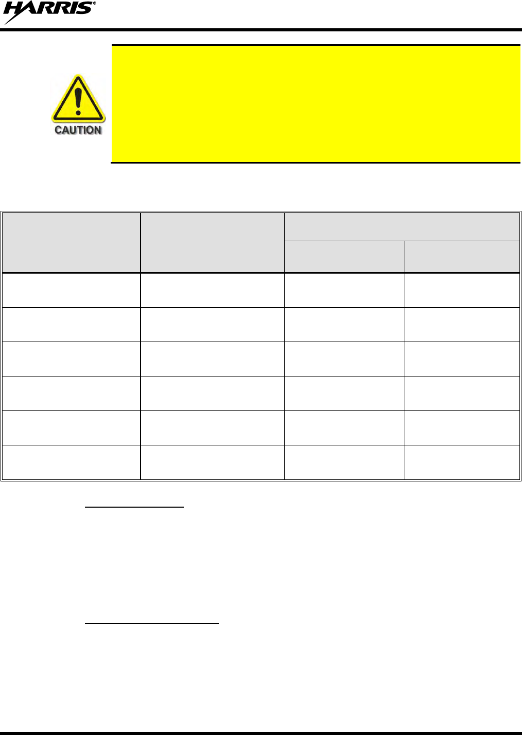
Table 1-1 lists the recommended minimum safe lateral distances for a controlled
environment and for unaware bystanders in an uncontrolled environment, from
transmitting antennas (i.e., monopoles over a ground plane, or dipoles). Table 1-1 has
the distances for the LBPA on a per antenna basis. This data is based upon the mobile
radio installed in a motor vehicle with the radio transmitting at its rated RF power
level. Transmit only when unaware bystanders are at least the uncontrolled
recommended minimum safe lateral distance away from the mobile radio’s transmitting
antenna.
Table 1-1: Recommended Minimum Safe Lateral Distance from Transmitting Antenna for VHF Low
Band Antennas (XG-100LPA Transmit/Receive Antenna)
(This table applies to Unity Mobile Low Band PAs only)
ANTENNA
PART NUMBER
ANTENNA DESCRIPTION
RECOMMENDED MINIMUM LATERAL HUMAN
BODY DISTANCE FROM TRANSMITTING ANTENNA
CONTROLLED
ENVIRONMENT
UNCONTROLLED
ENVIRONMENT
AN-125001-002 (mount) with
AN-025127-101 (element)
Low Band Mobile Antenna 30–35
MHz NMO DC ground
38.2 Inches
(97.0 Centimeters)
85.4 Inches
(217 Centimeters)
AN-125001-002 (mount) with
AN-025127-102 (element)
Low Band Mobile Antenna 34–37
MHz NMO DC ground
38.2 Inches
(97.0 Centimeters)
85.4 Inches
(217 Centimeters)
AN-125001-002 (mount) with
AN-025127-103 (element)
Low Band Mobile Antenna 37–40
MHz NMO DC ground
38.2 Inches
(97.0 Centimeters)
85.4 Inches
(217 Centimeters)
AN-125001-002 (mount) with
AN-025127-104 (element)
Low Band Mobile Antenna 40–47
MHz NMO DC ground
38.2 Inches
(97.0 Centimeters)
85.4 Inches
(217 Centimeters)
AN-125001-002 (mount) with
AN-025127-105 (element)
Low Band Mobile Antenna 45–48
MHz NMO DC ground
38.2 Inches
(97.0 Centimeters)
85.4 Inches
(217 Centimeters)
AN-125001-002 (mount) with
AN-025127-106 (element)
Low Band Mobile Antenna 47–50
MHz NMO DC ground
38.2 Inches
(97.0 Centimeters)
85.4 Inches
(217 Centimeters)
1.3.1 Mobile Antennas
The antenna(s) for the radios must be installed in accordance with Section 8 in this manual. Installation
guidelines presented in Section 8 are limited to metal-body motor vehicles or vehicles with appropriate
ground planes.
Use only the Harris-approved/supplied antenna(s) or an approved replacement antenna. Unauthorized
antennas, modifications, or attachments can cause the FCC RF exposure limits to be exceeded.
1.3.2 Approved Accessories
The radio has been tested and meets FCC RF guidelines when used with accessories supplied or
designated for use with it. Use of other accessories may not ensure compliance with the FCC’s RF
exposure guidelines, and may violate FCC regulations. For a list of approved accessories refer to Section
4 in this manual (begins on page 21) and/or the Products and Services Catalog.

14221-1200-4010, Rev. B
10
1.3.3 Contact Information
For additional information on RF exposure and other information, contact Harris using one of the contact
links listed in Section 4 on page 21.
1.4 RADIO FREQUENCY INTERFERENCE
1.4.1 FCC Part 15
This device complies with Part 15 of the FCC Rules. Operation is subject to the following two conditions:
1. This device may not cause harmful interference, and
2. This device must accept any interference received, including interference that may cause undesired
operation.
1.4.2 Industry Canada
This device complies with Industry Canada license-exempt RSS standard(s). Operation is subject to the
following two conditions: (1) this device may not cause interference, and (2) this device must accept any
interference, including interference that may cause undesired operation of the device.
Le présent appareil est conforme aux CNR d'Industrie Canada applicables aux appareils radio exempts de
licence. L'exploitation est autorisée aux deux conditions suivantes : (1) l'appareil ne doit pas produire de
brouillage, et (2) l'utilisateur de l'appareil doit accepter tout brouillage radioélectrique subi, même si le
brouillage est susceptible d'en compromettre le fonctionnement.
1.5 OCCUPATIONAL SAFETY GUIDELINES AND SAFETY TRAINING
INFORMATION
To ensure bodily exposure to RF electromagnetic energy is within the FCC allowable limits for
occupational use. Always adhere to the following basic guidelines:
The push-to-talk button should only be depressed when intending to send a voice message.
The radio should only be used for necessary work-related communications.
The radio should only be used by authorized and trained personnel. It should never be operated by
children.
Do not attempt any unauthorized modification to the radio. Changes or modifications to the radio may
cause harmful interference and/or cause it to exceed FCC RF exposure limits. Only qualified
personnel should service the radio.
Always use only Harris-authorized accessories (antennas, control heads, speakers/mics, etc.). Use of
unauthorized accessories can cause the FCC RF exposure compliance requirements to be exceeded.
The information listed above provides the user with information needed to make him or her aware of a RF
exposure, and what to do to assure that this radio operates within the FCC exposure limits of this radio.

14221-1200-4010, Rev. B
11
1.6 COMMON HAZARDS
The operator of any mobile radio should be aware of certain hazards common to the
operation of vehicular radio transmissions. Possible hazards include but are not
limited to:
Explosive Atmospheres — Just as it is dangerous to fuel a vehicle with its engine running, be sure to
turn the radio OFF while fuelling the vehicle. If the radio is mounted in the trunk of the vehicle, DO
NOT carry fuel containers in the trunk.
Areas with potentially explosive atmosphere are often, but not always, clearly marked. Turn the radio
OFF when in any area with a potentially explosive atmosphere. It is rare, but not impossible that the
radio or its accessories could generate sparks.
Interference To Vehicular Electronic Systems — Electronic fuel injection systems, electronic anti-
skid braking systems, electronic cruise control systems, etc., are typical of the types of electronic
devices that can malfunction due to the lack of protection from radio frequency (RF) energy present
when transmitting. If the vehicle contains such equipment, consult the dealer for the make of vehicle
and enlist the dealer’s aid in determining if such electronic circuits perform normally when the radio
is transmitting.
Electric Blasting Caps — To prevent accidental detonation of electric blasting caps, DO NOT use
two-way radios within 1000 feet (305 meters) of blasting operations. Always obey the “Turn Off
Two-Way Radios” (or equivalent) signs posted where electric blasting caps are being used (OSHA
Standard: 1926.900).
Radio Frequency Energy — To prevent burns or related physical injury from radio frequency
energy, do not operate the transmitter when anyone outside of the vehicle is within the minimum safe
distance from the antenna as specified in Table 1-1 (as applicable). Refer to Section 1.2 for additional
information.
Vehicles Powered By Liquefied Petroleum (LP) Gas — Radio installation in vehicles powered by
liquefied petroleum gas, where the LP gas container is located in the trunk or other sealed-off space
within the interior of the vehicle, must conform to the National Fire Protection Association standard
NFPA 58. This requires:
The space containing the radio equipment must be isolated and sealed from the space containing
LP gas containers and their fittings.
Outside filling connections must be used for the LP gas container.
The LP gas container space shall be vented to the outside of the vehicle.
Vehicles Equipped with Airbags — For driver and passenger safety, avoid mounting the radio’s
control head (or any other component) above or near airbag deployment areas. In addition to driver-
side and passenger-side front-impact airbags, some vehicles may also be equipped with side-impact
airbags. For occupant safety, verify the location of all airbags within the vehicle before installing the
radio equipment.
14221-1200-4010, Rev. B
12
1.7 SAFE DRIVING RECOMMENDATIONS
The American Automobile Association (AAA) advocates the following key safe driving recommenda-
tions:
Read the literature on the safe operation of the radio.
Keep both hands on the steering wheel and the microphone in its hanger whenever the vehicle is in
motion.
Place calls only when the vehicle is stopped.
When talking from a moving vehicle is unavoidable, drive in the slower lane. Keep conversations
brief.
If a conversation requires taking notes or complex thought, stop the vehicle in a safe place and
continue the call.
Whenever using a mobile radio, exercise caution.
1.8 OPERATING RULES REGULATIONS
Two-way radio systems must be operated in accordance with the rules and regulations of the local,
regional, or national government.
In the United States, this Unity mobile low band VHF amplifier must be operated in accordance with the
rules and regulations of the Federal Communications Commission (FCC). Operators of two-way radio
equipment must be thoroughly familiar with the rules that apply to the particular type of radio operation.
Following these rules helps eliminate confusion, assures the most efficient use of the existing radio
channels, and results in a smoothly functioning radio network.
When using a two-way radio, remember these rules:
Under U.S. law, operation of an unlicensed radio transmitter within the jurisdiction of the
United States may be punishable by a fine of up to $10,000, imprisonment for up to two (2)
years, or both.
It is a violation of FCC rules to interrupt any distress or emergency message. The radio operates in
much the same way as a telephone “party line.” Therefore, always listen to make sure the channel is
clear before transmitting. Emergency calls have priority over all other messages. If someone is
sending an emergency message – such as reporting a fire or asking for help in an accident, do not
transmit unless assistance can be offered.
The use of profane or obscene language is prohibited by Federal law.
It is against the law to send false call letters or false distress or emergency messages. The FCC
requires keeping conversations brief and confined to business. Use coded messages whenever
possible to save on-the-air time.
Using the radio to send personal messages (except in an emergency) is a violation of FCC rules. Send
only essential messages.
It is against Federal law to repeat or otherwise make known anything overheard on the radio.
Conversations between others sharing the channel must be regarded as confidential.
14221-1200-4010, Rev. B
13
The FCC requires self-identification at certain specific times by means of call letters. Refer to the
rules that apply to the particular type of operation for the proper procedure.
No changes or adjustments shall be made to the equipment except by an authorized or certified
electronics technician.
1.9 OPERATING TIPS
The following conditions tend to reduce the effective range of two-way radios and should be avoided
whenever possible:
Operating the radio in areas of low terrain, or while under power lines or bridges.
Obstructions such as mountains and buildings.
In areas where transmission or reception is poor, communication improvement may
sometimes be obtained by moving a few yards in another direction, or moving to a higher
elevation.
NOTE

14221-1200-4010, Rev. B
14
2. SPECIFICATIONS1
2.1 GENERAL
Dimensions (Height x Width x Depth):
XG-100LPA: 2.68 x 8.8 x 9.3 inches (6.81 x 22.4 x 23.6 centimeters)
(Includes bracket but not space required for cables)
XG-100LPA and XG-100M: 7.3 x 8.8 x 9.3 inches (18.5 x 22.4 x 23.6 centimeters)
(Includes bracket but not space required for cables)
Control Head, CH-100: 3.3 x 7.0 x 2.8 inches (8.4 x 17.8 x 7.1 centimeters)
(Does not include bracket and mounting screws)
Control Head, CH721: 2.4 x 6.9 x 3.9 inches (6 x 17.5 x 10 centimeters)
(Does not include bracket and mounting screws)
Weights
XG-100LPA and XG-100M: 13.6 pounds (6.17 kilograms), does not include bracket
Control Head, CH-100: 1.20 pounds (0.54 kilograms), does not include bracket
Control Head, CH-721: 1.25 pounds (0.57 kilograms), does not include bracket
Mounting Brackets: 1.25 pounds (0.57 kilograms) each
Cable, Interface: 1.25 pounds (0.57 kilograms)
Operating Ambient Temperature Range: -22 to +140° Fahrenheit (-30 to +60° Celsius)
Storage Temperature Range: -40 to +185° Fahrenheit (-40 to +85° Celsius)
Altitude
Operating: 15,000 feet (4572 meters) maximum
Storage/Shipment: 50,000 feet (15,240 meters) maximum
DC Supply Voltage Operating Range
For Full Performance: +13.6 Vdc ±10% (Normal range per TIA-603)
Overall Operating Range: +10.8 to +16.6 Vdc
Continuous without Damage: 0 to +17 Vdc
DC Supply Current (less control head and Unity mobile)
XG-100LPA
Receive: 1.1 amps maximum
Transmit at 30 Watts, VHF-Low: 7.25 amps typical, 10 amps maximum
Transmit at 100 Watts, VHF-High: 15 amps typical, 25 amps maximum
Quiescent/Off Current: 2 milliamps maximum
1 These specifications are primarily intended for the use of the installation technician. See the appropriate Specifications
Sheet for the complete specifications.

14221-1200-4010, Rev. B
15
DC Supply Current with CH-100 or CH-721 Control Head
With ½-Watt Speaker Output Power: 0.9 amps maximum
With 10-Watts Speaker Output Power: 2.0 amps maximum
With 15-Watts Speaker Output Power: 2.4 amps maximum
Standby Current (Muted): 0.6 amps maximum
Quiescent/Off Current: 100 microamps maximum
2.2 TRANSMITTER
Frequency Range: 33-48 MHz
Frequency Stability: ±0.5 ppm
Rated Power Output: 30 or 100 Watts (user selectable)
RF Output Impedance: 50 Ohms
Modulation Deviation: ±5 kHz
FM Hum and Noise: 50 dB
Spurious and Harmonic Emissions: -15 dBm
Adjacent Channel Power: >70 dBc
2.3 REGULATORY
FCC Identification Numbers:
XG-100MLPA AQZ-XG-100LPA
50-Watt XG-100M: AQZ-XG-100M00
Applicable FCC Rules: Part 80, Part 90, and Part 15
Industry Canada Certifications:
XG-100MLPA 122D-XG100LPA
50-Watt XG-100M: 122D-XG100M00
Applicable Industry Canada Rules: RSS-119
14221-1200-4010, Rev. B
16
3. INTRODUCTION
This manual contains product safety and installation-related procedures for the XG-100M Unity mobile
with its companion XG-100LPA VHF Low Band Power Amplifier. Installation procedures cover the
mounting and cabling of the equipment, as well as the basic testing of the mobile radio and control head.
An interconnection wiring diagram is included at the rear of this manual. Important product safety-related
information is presented in Section 1.
3.1 GENERAL INFORMATION
The XG-100LPA VHF Low Band Power Amplifier extends the versatility and interoperability of the
Unity XG-100M mobile by adding efficient transmission capability at 33 to 48 MHz. With 100 Watts of
power, user safety is ensured by broadening the coverage area of the mobile radio. Expanded
interoperability allows responders to communicate with multiple jurisdictions and agencies operating on
multiple frequencies and systems. The rugged mechanical package provides reliable performance in harsh
environments. The PA includes the following features:
Expands the versatility of the Unity XG-100M into VHF low band
Additional hardware module for low band transmit operation
User-selectable transmit power of 100 or 30 Watts
Durable construction meets the same MIL-STD-810G specifications as the Unity XG-100M
mobile
Designed to have the same dimensions as the chassis of the Unity XG-100M mobile
Stacks on the mobile to reduce the footprint required in constrained vehicular spaces
Provides three connections: power, radio, and antenna
The XG-100M/XG-100LPA combination for VHF Low Band operation requires XGP
Release R4A (or later) firmware.
3.2 EQUIPMENT MOUNTING
The XG-100M Unity mobile with its companion XG-100LPA VHF Low Band Power Amplifier is
designed for remote mounting in a motor vehicle’s trunk, or some other preferably unoccupied section in
a vehicle, such as a fire truck’s equipment shelf. Detailed radio equipment mounting procedures are
presented in Section 7 of this manual. Detailed control head mounting procedures are presented in Section
10 of this manual.
3.3 CONTROL HEADS
3.3.1 General Information
XG-100M Unity mobile with its companion XG-100LPA Low Band Power Amplifier is compatible with
either the CH-721 System model control head or the CH-100 touch screen control head. This equipment
provides the interface for the radio’s operator/user.
NOTE
14221-1200-4010, Rev. B
17
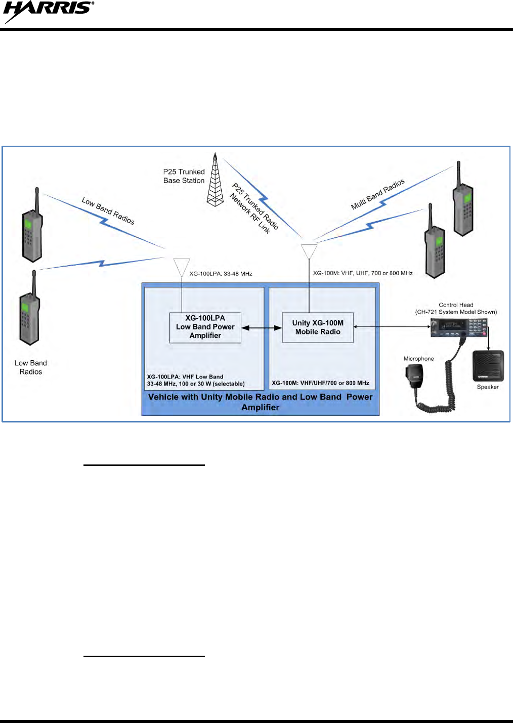
A 3-wire Controller Area Network (CAN) cable provides radio-to-control head(s) interconnection. One
end of the CAN cable connects to a CAN port on the rear of the Unity mobile radio unit (MRU) and the
other end connects to a CAN port on the rear of the control head. Between the radio and the control head,
the CAN link carries digitized microphone and speaker audio and controlling data such as button presses
and radio messages. For proper operation, the CAN link must be terminated appropriately on each end.
The control head provides the user/operator interface for the XG-100M Unity mobile with its companion
XG-100LPA VHF Low Band Power Amplifier.
Figure 3-1: Simplified Block Diagram Unity Low Band PA
3.3.2 CH-100 Control Head
The CH-100 control head features a 4.3-inch touch screen high-contrast sunlight-readable LCD color
display, providing an easy-to-use menu-driven operator interface. The front panel of the CH-100 head
features an easy-to-use on/off/volume control and group/channel selection controls, an emergency button,
a home button, a USB programming port, a transmit/receive busy indicator, and a microphone connector.
The CH-100 also features a Bluetooth® wireless interface for connection of optional equipment and it
provides support for radio and control head programming via the wireless connection.
The front panel of the CH-100 is shown in Figure 10-1 on page 56 and its rear panel is shown in Figure
10-2. Connectors located on the rear panel include a DC power connector, two (2) CAN port connectors
used for CAN link interconnections, an external speaker connector, a 9-pin serial port connector for
connecting optional equipment such as a mobile data terminal, and a 25-pin multi-function accessory
connector.
3.3.3 CH-721 Control Head
The CH-721 control head, shown in Figure 10-4, features a large 3-line graphical vacuum-fluorescent
display, front panel controls, and buttons for user control of the mobile radio, an internal high-power
audio amplifier to drive an externally-connected speaker, and a front panel microphone connector. It
14221-1200-4010, Rev. B
18
features a 12-key numeric keypad that provides Dual-Tone Multi-Frequency (DTMF) keypad
functionality and operator system/group selection control, three (3) preset buttons, and an
emergency/home button.
Shown in Figure 10-5 on page 58, the CH-721 System model control head has several connectors located
on its rear panel. These connectors include a DC power connector, two (2) CAN port connectors used for
CAN link interconnections, an external speaker connector, a 9-pin serial port connector for connecting
optional equipment such as a mobile data terminal, and a 25-pin multi-function accessory connector.
3.4 OPERATING POWER
The XG-100M Unity mobile radio with its companion XG-100LPA VHF Low Band Power Amplifier is
powered by an external +13.6-volt (nominal) DC power source. In mobile applications, the motor
vehicle’s electrical system is used as the source of DC power. The Unity mobile radio and its companion
XG-100LPA are separately fused. For detailed specifications, see Section 2 of this manual which begins
on page 14.
The control head(s) connected to the radio is powered by the same DC power source, but fused separately
from the XG-100M and XG-100LPA. When the control head is powered-up by the operator, it “wakes
up” the MRU radio by transmitting data to the radio over the CAN link.
Harris recommends the buyer use only a Harris-authorized representative to install
and service this product. The warranties provided to the buyer under the terms of sale
shall be null and void if this product is installed or serviced improperly, and Harris shall
have no further obligation to the buyer for any damage caused to the product or to any
person or personal property.
3.5 RADIO PROGRAMMING
Radio Personality Manager Release R11A or later is required to program the XG-
100M/XG-100LPA radio for VHF Low Band transmit operation.
Unless otherwise stated, all radio installation and test procedures presented in this manual assume the
radio has been programmed by radio network administration personnel before it is delivered to radio
installation personnel. Programming instructions are beyond the scope of this manual.
The Radio Personality Manager (RPM) software application TQS3385 (part number SK-104768-001) is
used to program the XG-100M/XG-100LPA for VHF Low Band conventional operation. RPM can also
be used to flash program new operating software (i.e., firmware) into an XG-100M mobile radio. Refer to
the radio’s maintenance manual for additional information.
For additional RPM information, refer to its built-in online help and/or RPM Software Release Notes,
publication number MS-012550-001(TQS3385).
An XG-100M radio with a CH-100 control head can use a TIA/EIA/RS-232C serial cable connection, a
USB serial cable connection, or a Bluetooth wireless connection for programming operations. The
TIA/EIA/RS-232C serial cable connects to the 9-pin D-subminiature (DB-9) connector on the rear of the
radio. For USB and Bluetooth links, the CH-100 control head provides the connection path.
NOTE
14221-1200-4010, Rev. B
19
An XG-100M radio with a CH-721 control head must use a TIA/EIA/RS-232C serial cable connection for
programming. The serial cable connects to the 9-pin D-subminiature (DB-9) connector on the rear of the
radio.
A USB or a Bluetooth link is the preferred connection method for an XG-100M radio with a
CH-100 control head. These links support programming of up to ten (10) personalities/mission
plans into the radio. Only one personality/mission plan is active at a time.
An XG-100M radio with a CH-721 control head can only have one (1) personality/mission
plan. It is always active.
A personality/mission plan loaded into the radio via a TIA/EIA/RS-232C serial link cannot be
extracted (read back) via a USB or Bluetooth link.
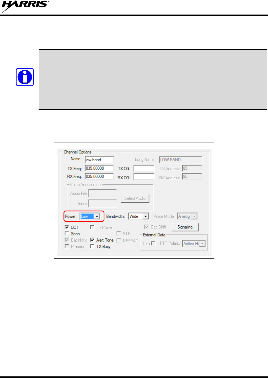
Personality for the VHF Low Band power output is setup in RPM by selecting the Sets->Conventional
Frequency Set controls and select the Conventional Frequency Set tab. In the Channel Options
section, set Power to either Low (30 Watts) or High (100 Watts).
Figure 3-2: Setting Unity Low Band PA in RPM Personality
NOTE

14221-1200-4010, Rev. B
20
3.6 RELATED PUBLICATIONS
The following publications contain additional information about this radio equipment:
Quick Guide for Unity XG-100M Mobile Radio
with CH-100 Control Head:
14221-1200-1010
Quick Guide for Unity XG-100M Mobile Radio
with CH-721 Control Head:
14221-1200-1000
Operator’s Manual for Unity XG-100M Mobile Radio
with CH-100 Control Head:
14221-1200-2010
Operator’s Manual for Unity XG-100M Mobile Radio
with CH-721 Control Head:
14221-1200-2000
Installation Manual for XG-100M:
14221-1200-4440
Maintenance Manual for XG-100M
14221-1200-5000
The Product Safety Manual and Quick Guides (for radio operators) are included with each mobile radio
equipment package when the package ships from the factory. The Operator’s Manuals and the Quick
Guides are also available online at http://pspc.harris.com/Products/Mobile/unitymobile.aspx without a
login. All other XG-100M and XG-100LPA related mobile radio publications can be obtained from
www.pspc.harris.com via an Information Center login (i.e., a user name and password are required). The
publications are in Tech-Link’s Technical Manual Library.

14221-1200-4010, Rev. B
21
4. CUSTOMER SERVICE
4.1 TECHNICAL SUPPORT
The Harris Technical Assistance Center (TAC) resources are available to help you with overall system
operation, maintenance, upgrades, and product support. TAC is your point of contact when you need
technical questions answered.
Product specialists, with detailed knowledge of product operation, maintenance, and repair, provide
technical support via a toll-free telephone number (in North America). Support is also available through
mail, fax, and e-mail.
For more information about technical assistance services, contact your sales representative, or call the
Technical Assistance Center directly at:
North America: 1-800-528-7711
International: 1-434-385-2400
Fax: 1-434-455-6712
E-mail: PSPC_tac@harris.com
4.2 TECH-LINK
For more information about this and other Harris PSPC products, check out our Tech-Link service at:
https://premier.pspc.harris.com/
Tech-Link is a one stop link to Technical Documentation (downloadable PDFs), Software Revisions,
Feature Encryption, pictorials of parts and accessories, and other information pertaining to our products.
This is information that will enhance your service efforts; 24 hours a day and 7 days a week.
4.3 CUSTOMER CARE
If any part of the system equipment is damaged on arrival, contact the shipper to conduct an inspection
and prepare a damage report. Save the shipping container and all packing materials until the inspection
and the damage report are completed. In addition, contact the Customer Care center to make
arrangements for replacement equipment. Do not return any part of the shipment until you receive
detailed instructions from a Harris representative.
Contact the Customer Care center at http://www.pspc.harris.com/CustomerService or:
North America:
Phone Number: 1-800-368-3277
Fax Number: 1-321-409-4393
E-mail: PSPC_CustomerFocus@harris.com
International:
Phone Number: 1-434-455-6403
Fax Number: 1-321-409-4394
E-mail: PSPC_InternationalCustomerFocus@harris.com
14221-1200-4010, Rev. B
22
5. UNPACKING AND CHECKING THE EQUIPMENT
Upon receipt of the Harris equipment, carefully unpack the equipment and verify that the order is
complete. Inspect the equipment for any shipping damage. If there is any damage to the equipment,
contact the carrier immediately and have their representative verify the damage. If you fail to report the
shipping damage immediately, you may forfeit any claim against the carrier.
When unpacking the equipment, check the contents against the packing list. Contact your Harris
representative and the carrier if any discrepancies are noted.
After verifying all equipment is accounted for, proceed with the installation.
After removal from the carton, examine the mobile radios, control head, and other
components for broken, damaged, loose, or missing parts. If any are noted, contact the
Customer Care center (see page 21) immediately to discuss and arrange the return of the
equipment to Harris for replacement. Any unauthorized attempts to repair or modify this
equipment will void the warranty and could create a safety hazard.
5.1 MATERIALS
A typical set of installation materials for a Unity XG-100M mobile radio with XG-100LPA VHF Low
Band Amplifier includes:
Unity XG-100M Mobile Radio -refer to Table 5-1.
Unity XG-100LPA 100W Low Band Power Amplifier -refer to Table 5-1.
CH-100 Control Head [12099-1200-01; catalog number XMCP9R].
or
CH-721 System Control Head [part number CU23218-0004; catalog number MAMW-NCP9F].
Standard Microphone [part number MC-101616-041; part of catalog number MAMW-NMC7Z].
Installation Kits:
Unity XG-100LPA – contents listed in Table 5-2.
XG-100M with Remote CH-100 Control head - contents listed in Table 5-3.
XG-100M with Remote CH-721 System Control head - contents listed in Table 5-4.
Two (2) or Three (3) Antennas - refer to Table 5-5 for VHF Low Band antennas and Table 5-6 for
other XG-100M antenna options.
14221-1200-4010, Rev. B
23
Table 5-1: Catalog and Part Numbers for Unity XG-100M Mobile Radio with XG-100LPA
CATALOG NUMBER
PART NUMBER
DESCRIPTION
XM-100F or
XM-100F-D01 or
XM-100F-D02
12099-1000-01
Unity XG-100M Mobile Radio, 136-870 MHz
Unity XG-100M Mobile Radio, 136-520 MHz
Unity XG-100M Mobile Radio, 136-174, 762-870 MHz
XM-100LPA
12099-3500-02
100W VHF Low Band Power Amplifier
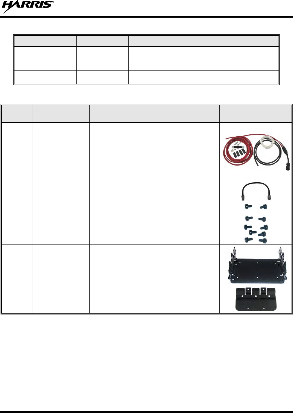
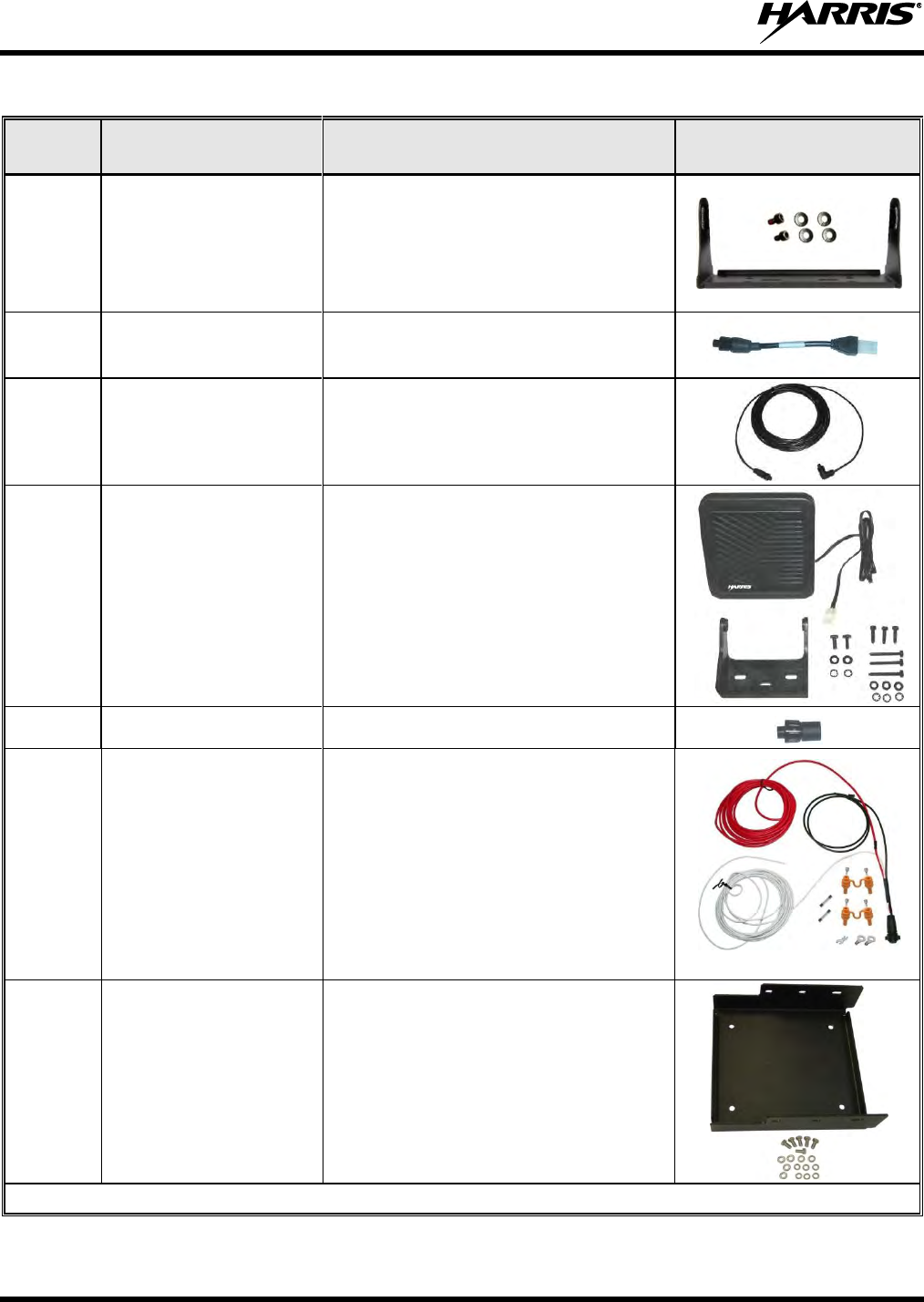
Table 5-2: Installation Kit XM-ZN2G for XG-100LPA
QTY
PER KIT
PART NUMBER
DESCRIPTION
ILLUSTRATION
1
14002-0167-01
Cable, DC Power for High-Power Applications,
Includes:
(1) DC Power Cable with a 20-Foot Red Wire,
(1) water-resistant inline HEB-BB fuse holder,
(2) 30-amp BAF-30 fuses,
(2) ring terminals, and
(4) heat-shrink tubing, 50mm long
1
W90-0223-001
Cable, RF; BNC Male to BNC Male, 12"
1
AD00006
Screws: #8-32 Pan-Head (Package of 4
screws)
1
SC-018424
Screws: M5 x 10 mm Philips-Head SEMS
Screws (Package of 12 screws)
1
1000003678
Bracket, Base
2
FM-018205
Extension Bracket
14221-1200-4010, Rev. B
24
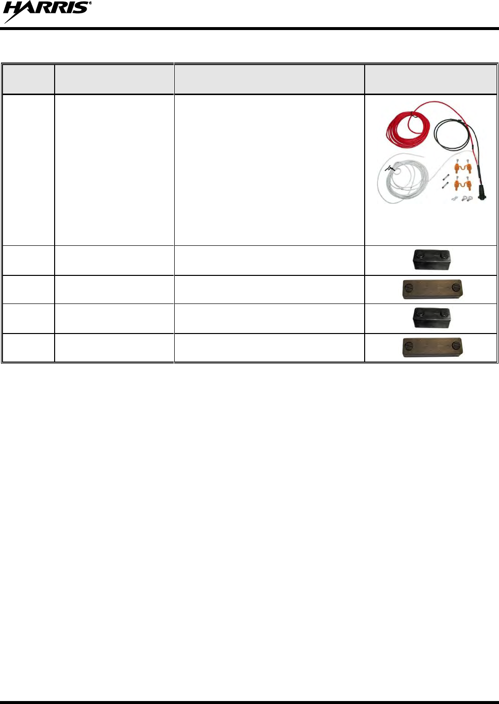
Table 5-3: Installation Kit XMZN9A for XG-100M with CH-100 Control Head
QTY
PER KIT
PART NUMBER
DESCRIPTION
ILLUSTRATION
1
12099-1500-01
Kit, Swivel Mounting, includes:
(1) U-Shaped Swivel-Mount Bracket,
(2) Socket-Head Cap Screws, M4x8mm,
(2) Flat Washers, and
(2) Lock Washers
1
MAMROS0034-NN006
Cable, Speaker; 6-Inch, Straight
Connector
1
CA-009562-030
Cable, CAN; 30 feet, Right-Angle-to-
Straight Connectors
1
LS102824V10
Speaker, External Mobile; 4 Ohm,
20-Watt (with 4.6-foot cable)
2
CD-014027-001
Terminator, CAN; 3-Pin, Straight Body
1
CA-012616-001
Cable, DC Power for CH-100, Includes:
(1) DC Power Cable with straight
connector,
(2) waterproof inline HFB-type fuse
holders,
(1) 3-amp AGC fuse,
(1) 5-amp AGC fuse
(2) ring terminals, and
(1) spade terminal
1
KT23117
Kit, Bracket. Includes Base Bracket
FM103111V1 and M5 hardware
Continued…
14221-1200-4010, Rev. B
25
Table 5-3: Installation Kit XMZN9A for XG-100M with CH-100 Control Head
QTY
PER KIT
PART NUMBER
DESCRIPTION
ILLUSTRATION
1
CA-012365-001
Cable, DC Power for XG-100M,
Includes:
(1) DC Power Cable with straight
connector,
(2) waterproof inline HFB-type fuse
holders,
(1) 3-amp AGC fuse,
(1) 15-amp AGC fuse, (radio Application)
(1) 20-amp AGC fuse, (not used)
(2) ring terminals, and
(1) spade terminal
1
FM-104859-001
Cap, Waterproof (For control head’s DB-9
serial port connector)
1
FM-104859-002
Cap, Waterproof (For control head’s DB-25
connector)
1
FM-104859-003
Cap, Waterproof (For radio’s DB-9
connector)
1
FM-104859-004
Cap, Waterproof (For radio’s DB-25
connector)
14221-1200-4010, Rev. B
26
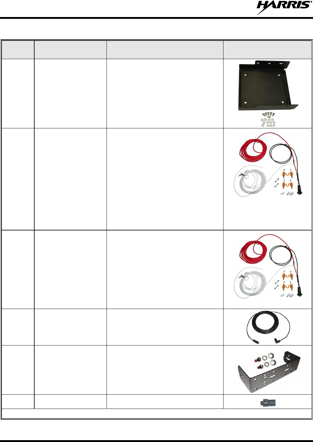
Table 5-4: Installation Kit XMZN7R for XG-100M with CH-721 Control Head
QTY
PER KIT
PART NUMBER
DESCRIPTION
ILLUSTRATION
1
KT23117
Kit, Bracket. Includes Base Bracket
FM103111V1 and M5 hardware
1
CA-012365-001
Cable, DC Power for XG-100M,
Includes:
(1) DC Power Cable with straight
connector,
(2) waterproof inline HFB-type fuse
holders,
(1) 3-amp AGC fuse,
(1) 15-amp AGC fuse, (radio
Application)
(1) 20-amp AGC fuse, (not used)
(2) ring terminals, and
(1) spade terminal
1
CA-012616-001
Cable, DC Power for CH-721, Includes:
(1) DC Power Cable with straight
connector,
(2) waterproof inline HFB-type fuse
holders,
(1) 3-amp AGC fuse,
(1) 5-amp AGC fuse
(2) ring terminals, and
(1) spade terminal
1
CA-009562-030
Cable, CAN; 30 feet, Right-Angle-to-
Straight Connectors
1
KT-008608
Kit, CH-721 Mounting Bracket. Includes
(1) U-Shaped Mounting Bracket, (2)
¼-Inch #8-32 stainless-steel screws, (2)
stainless-steel flat washers and (2)
stainless-steel lock washers
2
CD-014027-001
Terminator, CAN; 3-Pin, Straight Body
Continued…
14221-1200-4010, Rev. B
27
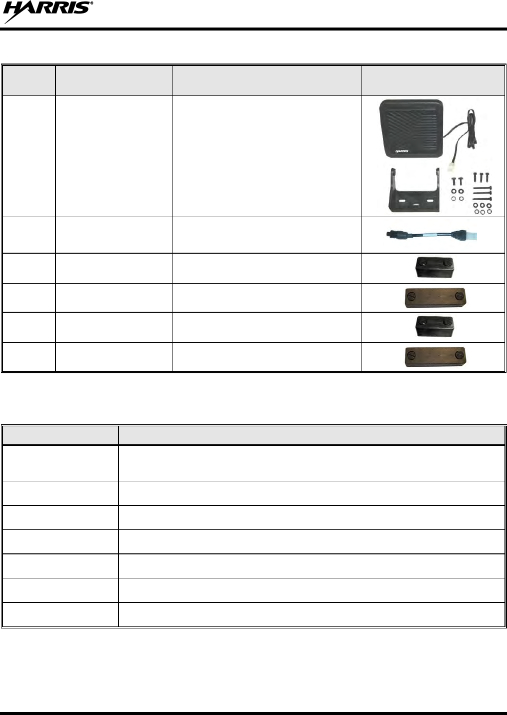
Table 5-4: Installation Kit XMZN7R for XG-100M with CH-721 Control Head
QTY
PER KIT
PART NUMBER
DESCRIPTION
ILLUSTRATION
1
LS102824V10
Speaker, External Mobile; 20-Watt (with
4.6-foot cable)
1
MAMROS0034-NN006
Cable, Speaker; 6-Inch, Straight
Connector
1
FM-104859-001
Cap, Waterproof (For control head’s DB-9
serial port connector)
1
FM-104859-002
Cap, Waterproof (For control head’s
DB-25 connector)
1
FM-104859-003
Cap, Waterproof (For radio’s DB-9
connector)
1
FM-104859-004
Cap, Waterproof (For radio’s DB-25
connector)
Table 5-5: XG-100LPA Antenna Elements and Mount Options
PART NUMBER
DESCRIPTION
AN-125001-002
Antenna Mount: Standard Rooftop, NMO Mounting Base, 15-foot (4.6-meter)
RF-195 (or equivalent) Low-Loss RF Cable, Male TNC RF Connector.
AN-025127-101
Antenna Element: Low Band Mobile Antenna 30–35 MHz NMO DC ground.
AN-025127-102
Antenna Element: Low Band Mobile Antenna 34–37 MHz NMO DC ground.
AN-025127-103
Antenna Element: Low Band Mobile Antenna 37–40 MHz NMO DC ground.
AN-025127-104
Antenna Element: Low Band Mobile Antenna 40–47 MHz NMO DC ground.
AN-025127-105
Antenna Element: Low Band Mobile Antenna 45–48 MHz NMO DC ground.
AN-025127-106
Antenna Element: Low Band Mobile Antenna 47–50 MHz NMO DC ground.
14221-1200-4010, Rev. B
28
Table 5-6: XG-100M Antenna Elements and Mount Options
PART NUMBER
DESCRIPTION
AN-125001-002
Antenna Mount: Standard Rooftop, NMO Mounting Base, 15-foot (4.6-meter)
RF-195 (or equivalent) Low-Loss RF Cable, Male TNC RF Connector.
AN-125001-004
Antenna Mount: Thick Rooftop, NMO Mounting Base, 15-foot (4.6-meter) RF-195
(or equivalent) Low-Loss RF Cable, Male TNC RF Connector.
AN-125001-006
Antenna Mount: GPS Combo Rooftop, NMO Mounting Base, 17-foot (5.1-meter)
RF-195 (or equivalent) Low-Loss RF Cable, Male TNC RF Connector; 17-foot
(5.1-meter) RG174/U (or equivalent) GPS RF Cable with Male SMA RF Connector
(attached); 2.7 to 3.3 Vdc or 4.8 to 5.2 Vdc Bias.
AN-125001-008
Antenna Mount: Magnetic, NMO Mounting Base, 15-foot (4.6-meter) RF-195 (or
equivalent) Low-Loss RF Cable, Male TNC RF Connector.
12099-0310-01
(Cat. No. XMAN6H)
Antenna Element: Multi-Band (136 to 174 MHz, 380 to 520 MHz, and 762 to 870
MHz), NMO, Factory Tuned.
12099-0330-01
(Cat. No. XMAN6J)
Antenna Element: Multi-Band (136 to 174 MHz/3 dBi, 380 to 520 MHz/3 dBi, and
762 to 870 MHz/6 dBi), NMO, Factory Tuned, 100-Watt.
AN-025187-001
(Cat. No. XMAN5F)
Antenna: GPS Receive-Only, Roof-Mount, 17-foot (5.2-meter) RG174/U (or
equivalent) RF Cable with Male SMA RF Connector (attached); 2.7 to 3.3 Vdc or
4.8 to 5.2 Vdc Bias.
AN-025187-003
(Cat. No. XMAN3L)
Antenna: GPS Receive-Only, Magnetic-Mount, 17-foot (5.2-meter) RG174/U (or
equivalent) RF Cable with Male SMA RF Connector (attached); 2.7 to 3.3 Vdc or
4.8 to 5.2 Vdc Bias.
14221-1200-4010, Rev. B
29
6. PLANNING THE INSTALLATION
6.1 GENERAL INFORMATION
Before beginning the radio installation, plan it carefully so it will meet the following requirements:
The installation is safe for the operator and passengers within the vehicle.
The equipment is installed away from the airbag deployment areas.
The installation allows for convenient access by the operator, as applicable (i.e., the control head).
The equipment is protected from water damage.
The installation is neat and allows easy service access.
The radio is mounted in a location assuring the vehicle occupant’s safety and out of the way of
passengers and auto mechanics.
See Section 6.3 on page 30 for additional requirements on equipment locations.
A professional radio installer should perform the installation!
6.2 TOOLS REQUIRED
The following list of equipment is recommended for the installation. Equivalents may be used unless
otherwise specified:
Crimp Tool for Non-Insulated Terminals:
Thomas & Betts WT-111-M
Crimp Tool for Insulated Terminals: Klein
1005
Crimp Tool for 35/50-Watt Radio
Installations (Fuse Holder): Thomas & Betts
– WT-112M or California Terminal Products
No. 1250 or Channelock No. 909
Crimp Tool for 110-Watt Radio Installations
(Fuse Holder and 6-AWG Ring Terminals):
Molex 64001-3900 or 3M TH-450.
3-Blade Coax Cable Stripper for RG-58 Cable
similar to Tyco Electronics 1490490-1
(includes blades)
Ratcheting Hex-Crimp Tool for 50-Ohm TNC
and BNC RF Connectors and RG-58 Cable
similar to Tyco Electronics 58433-2 (includes
Crimper 354940-1 and Die Set 58436-1) or
Emerson Network Power 24-9960P
Non-Metallic Fish Tape, 25-Foot: Klein-Lite
50156
Two Pairs of Soft-Jaw Pliers: Tessco 450520
or equivalent
Flush-Cut and Large Wire Cutters
Phillips-Head Screwdrivers, #1 and #2
Flat-Blade Screwdrivers, ⅛ and ¼-inch tips
⅛-Inch Hex Key Wrench (Allen Wrench)
5/16-Inch Combination or Open-End Wrench
Socket and/or Nut Driver Sets
¾-Inch or ⅜-Inch Hole Saw with Depth
Protection: ¾-Inch = Ripley HSK 19 or
Antenex HS34; ⅜-Inch = Antenex HS38
Clutch-Type (i.e., with torque limit) Cordless
Drill with Drill Bits and Driver Bits
Deburring Tool (for ⅜-inch and smaller
holes)
Tie Wraps: 6-inches or larger
Various Fasteners (e.g., machine screws and
nuts, Tek screws, etc.)
14221-1200-4010, Rev. B
30
6.3 LOCATING COMPONENTS
Plan the mounting locations of all components (LBPA, MRU, CH-100/CH-721, antennas, cables, etc.)
and determine the routes for all wiring and cables. Particularly consider the connection of the control head
for planning purposes.
Determine the customer’s preferences, if any, for location of components. Comply with these
preferences as long as they are consistent with safety recommendations and guidelines presented in
this manual, and other generally accepted professional radio installation practices.
Nominal dimensions for the LBPA, MRU, and the CH-100/CH-721 are listed in Section 2.1 of this
manual (page 14). These dimensions do not include any clearance space required for cabling, air
circulation, access to mounting hardware, etc. Always plan for and include adequate clearance around
the radios.
The LBPA and MRU must be located and mounted within approximately twelve (12) inches of each
other.
Verify sufficient clearance behind the radios is provided so cables will not be stressed, crushed,
twisted, or bent at severe angles. Also, the front and sides must have clearance for air circulation,
access to mounting hardware, etc.
Connections at the LBPA and MRU are made through both “pigtail” type cables exiting the rear of its
two radios, and panel-mount type connectors. This design minimizes the stresses associated with
mating connections and it allows for easy connector mating. However, stresses can still be induced if
adequate service looping is not employed. Connections to the control head is made with connectors
mounted on the rear panel of each head, instead of “pigtail” type cables.
Antennas: The radios’ two transmit/receive antennas must be at least three (3) feet (0.92 meters)
apart. However, further antenna separation is recommended, if possible. Refer to Section 8 (page 40)
for antenna installation details.
All cables should have a service loop near each connector end. Do not bend the cables at
severe angles near the connector end. After all components are installed, verify no cable is
under any tension. Failure to do so may lead to damaged cables, causing intermittent radio
operation or complete radio failure.
14221-1200-4010, Rev. B
31
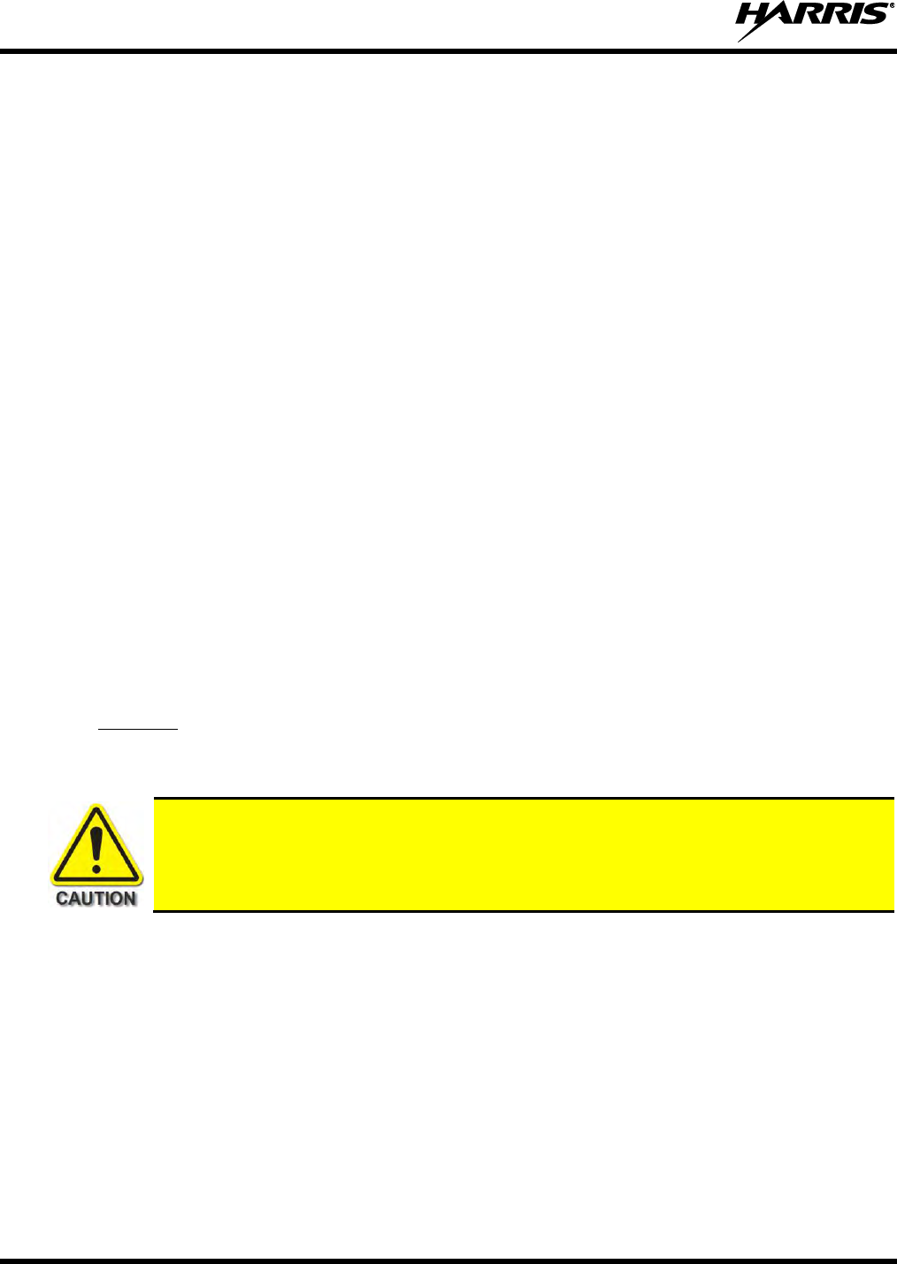
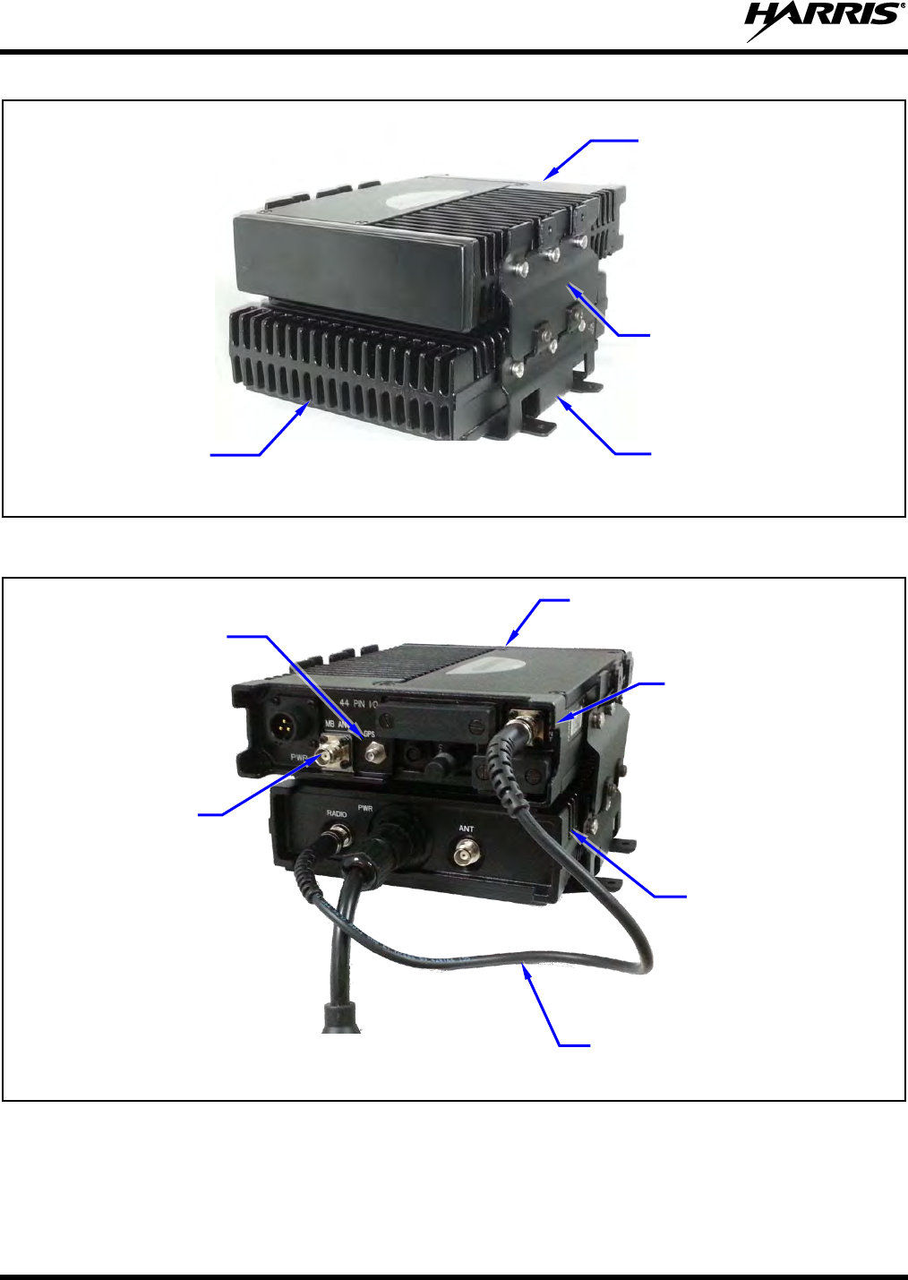
Figure 6-1: Unity XG-100LPA Low Band Power Amplifier - Front and Rear Views
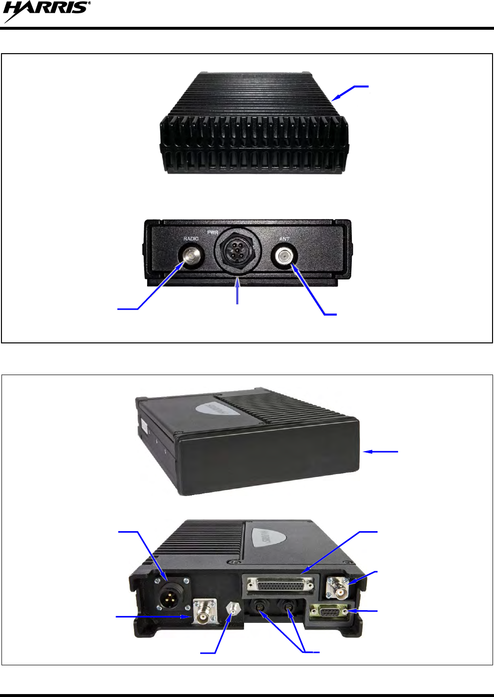
Figure 6-2: Unity XG-100M Remote-Mount Mobile Radio - Front and Rear Views
CAN Port Connectors (2 places)
Antenna Connector
(Female TNC)
DC Power Connector
(3-Pin Connector)
GPS Antenna Port (Female SMA)
44-Pin I/O Connector
9-Pin Serial Port
Connector
RF Connector for VHF
Low Band
(Female BNC)
Low Band Power
Amplifier
(XG-100LPA)
Radio Connector
(Female BNC)
Low Band Antenna Connector
(Female TNC)
DC power connector
Unity XG-100M
Multiband Mobile
Radio
14221-1200-4010, Rev. B
32
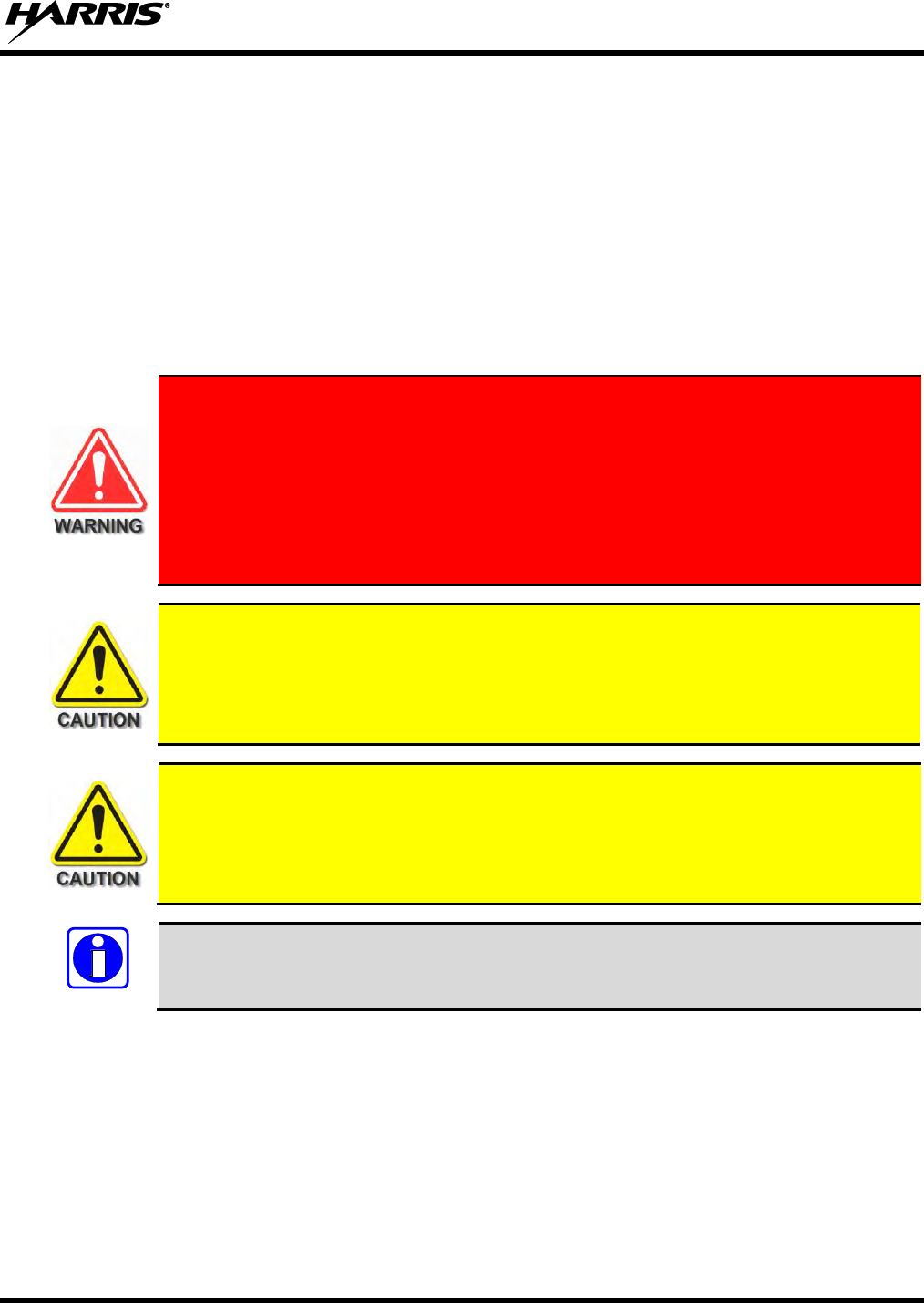
Figure 6-3: XG-100LPA/XG-100M Front-Side View
Figure 6-4: XG-100LPA/XG-100M Rear View
(Shown Without Any Installation-Related Cables Connected)
Low Band PA
(XG-100LPA)
GPS Antenna Cable’s
SMA Connector
Low band PA Antenna
Connector (Female TNC)
MRU to LBPA RF Cable
(Male BNC to Male BNC)
MRU Radio (XG-100M)
Multiband Antenna
Connector
MRU Radio
(XG-100M)
Low band PA
(XG-100LPA)
Base Bracket
(Included with Installation
Kit)
Extension Bracket
(2 places; included with
Installation Kit)
14221-1200-4010, Rev. B
33
7. MOUNTING THE RADIO EQUIPMENT
This section provides details on mounting the Low Band Power Amplifier and radio equipment assembly.
The preferred mounting is on top of a firm, flat surface. See Figure 6-3, Figure 6-4, and refer to the
respective wiring diagram at the end of this manual as necessary. Control head installation procedures are
included in Section 10 that begins on page 55.
The Low Band Power Amplifier and radio equipment combination weighs approximately 15- pounds
(6.8 kilograms). This includes the LBPA, MRU radio, and mounting brackets. Consider this weight when
selecting a mounting surface. Refer to the specifications listed in Section 2.1 (page 14) of this manual for
radio and control head weight specifications.
At a minimum, the mounting surface should be 16-gauge (approximately 1/16-inch
thick) steel sheet metal. Mounting to plastic or other material with low tensile and
shear strength could lead to an unsafe and/or failed mounting condition, turning the
Unity mobile and Low Band Power Amplifier and its base bracket into a projectile
during a high-shock incident such as a motor vehicle accident. If the selected mounting
surface does not meet the minimum 16-gauge steel sheet metal requirement, the
surface should be reinforced with a metal backing plate (not supplied) or it should be
reinforced using some other approved mounting method.
Though generally mounted in a trunk or remote location, the Unity mobile and Low Band
Power Amplifier must be kept away from heat sources. Mounting it in a location which is
out of direct sunlight is recommended but not required. Adequate ventilation space must be
provided to the rear and side fins. The radio reduces its RF output power when its ambient
temperature exceeds approximately +140o Fahrenheit (+60o Celsius).
Before drilling holes and/or installing mounting screws, verify these operations will not
damage or interfere with any existing vehicle component (fuel tank, fuel line, transmission
housing, existing vehicle wiring, etc.). Always check to see how far the mounting screws
will extend below the mounting surface prior to installation. Always deburr drilled holes
before installing screws.
Prior to beginning the installation, verify the Unity mobile has the proper version of
software installed and it has been configured for customer usage.
7.1 INSTALL THE MOUNTING BRACKETS
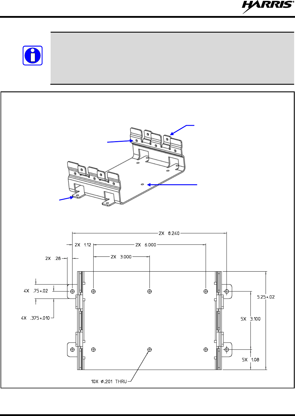
Two base brackets are included with the installation kits. One bracket (1000003678) is used to mount the
LBPA and the other base bracket (FM103111V1) is used to mount the radio. However, the preferred
installation method is to mount the radio above the LBPA using the LBPA base bracket and the two (2)
extension brackets (FM-018205) included in the LBPA installation kit.
Typically, the base brackets are mounted in the vehicle’s trunk, on the top surface of a trunk tray, or on
the trunk floor. However, it can be suspended from the trunk’s rear deck if the surface is completely flat,
does not require any shimming, and the gauge of deck’s sheet metal is high (16-guage minimum).
NOTE
14221-1200-4010, Rev. B
34
The RF cable (W90-0223-001) which interconnects the MRU VHF Low Band connector to
the RF connector on the LBPA Radio Connector is approximately 12-inches long. If the
units are mounted separately, they must be located so the respective connectors of the cable
can mate to the connectors on the rear of the units. Typically, both brackets should be
mounted within approximately twelve (12) inches of each. The brackets/radios may be
oriented parallel or perpendicular to each other.
TOP VIEW WITH SCREW HOLE DIMENSIONS (In Inches)
Figure 7-1: Base Bracket 1000003678 (Part of XM-ZN2G Installation Kit)
NOTE
Side Mounting
Tabs
(4 places)
Bracket-To-Vehicle Mounting
Surface Screw Holes
(10 places)
Bracket-To-Radio Screw Holes
(6 places, 3 each side)
Four (4) Upper-Most Holes
(2 each side) Used to Attach
Extension Brackets
14221-1200-4010, Rev. B
35
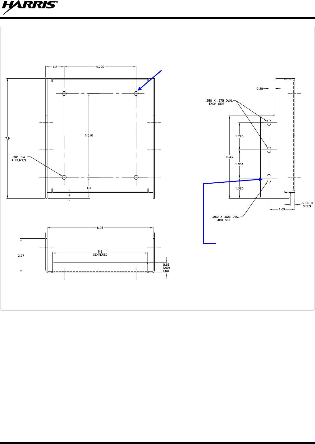
TOP VIEW SIDE VIEW
Dimensions are in Inches
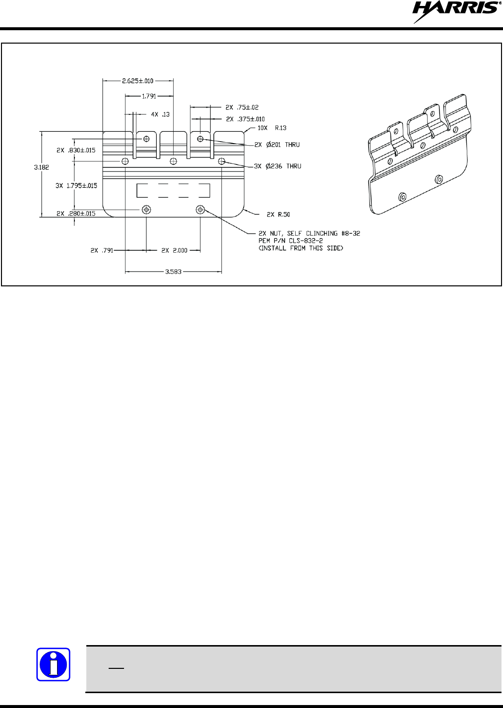
Figure 7-2: Base Bracket FM103111V1 in Bracket Kit KT23117
When installed in a bracket, the radio and LBPA protrude several inches from the bracket’s front and
back edges. Therefore, when selecting an exact mounting location, verify sufficient distance at the front
and back for this plus additional clearance. A minimum distance of three (3) inches is required from the
rear edge of the bracket; however, four (4) inches or more is recommended to make radio installation and
removal easier. A minimum distance of two (2) inches is recommended from the front edge of each
bracket. The Extension Brackets are left/right symmetrical and the Base Brackets are front/back
symmetrical.
Bracket-To-Vehicle
Mounting Surface Screw
Holes (4 places)
Bracket-To-Radio Screw Holes
(6 places, 3 each side)
14221-1200-4010, Rev. B
36
(Dimensions are in Inches)
Figure 7-3: Extension Bracket FM-018205 (Part of XM-ZN2G Installation Kit)
1. Select a location for the base bracket.
If the units are being mounted separately, select a location for the MRU’s Base Bracket and a location
for the LBPA’s Base Bracket. As previously stated, both brackets should be mounted within
approximately twelve (12) inches of each other so the section of the cable which interconnects the
two radios will have sufficient length.
2. Use the Base Bracket(s) as a template or use the dimensional information shown in Figure 7-1 and/or
Figure 7-2, mark and drill mounting holes into the mounting surface for the bracket(s).
3. Deburr all newly drilled mounting holes.
4. Set bracket or brackets in place, install, and tighten the mounting screws.
For the LBPA Base Bracket 1000003678, use at least six (6) screws per bracket: Four (4) in the screw
holes of a bracket’s side tabs and two (2) in its center-most screw holes. If the installation prevents
the installation of six screws, a minimum of four screws installed in the side tabs’ holes is required.
For the MRU Base Bracket FM103111V1, use four (4) screws to secure the bracket to the mounting
surface.
As all installations differ, bracket-to-vehicle mounting screws are not included. Using #10 stainless-
steel machine screws, stainless steel flat washers, and stainless steel self-locking nuts is
recommended. Alternately, #10 stainless steel self-drilling screws, and stainless-steel flat washers
may be used to speed installation time and/or if the underside of the mounting surface is not easily
accessible. Self-drilling screws such as “TEK” screws do not require drilling of a pilot hole prior to
installation.
Do not use common self-threading sheet metal screws because they will loosen over time
with vehicle vibrations.
NOTE

14221-1200-4010, Rev. B
37
5. Verify both base brackets are firmly secured to the mounting surface. A secure mount prevents
unreasonable vibration, which could damage the radio, cause its cable connections to loosen, or both.
6. XG-100LPA mounted with XG-100M Only:
a. Attach an Extension Bracket (FM-018205) to each side of LBPA Base Bracket (1000003678).
b. Push each Extension Bracket firmly down into the Base Bracket so it is firm and flush.
c. Secure the Extension Bracket to the Base Bracket using two #8-32 pan-head screws per Extension
Bracket and tighten.
7.2 MOUNT THE EQUIPMENT INTO THE BRACKETS
7.2.1 MRU and LBPA Mounting
Mount the MRU and LBPA into the brackets using either the LBPA and MRU stacking procedure or the
mounting separately procedure.
To Stack LBPA and MRU using the LBPA Base Bracket:
Install the LBPA and the MRU into the LBPA Base Bracket using the following procedure. An exploded
view assembly diagram is shown in Figure 7-4.
1. Slide the LBPA into the Base Bracket 1000003678. The LBPA connector end must face towards the
cabling area of the installation.
2. Secure the LBPA to the bracket using six (6) M5 Philips-head screws (SC-018424), three (3) per side.
These screws have a captive-type (SEMS) lock washer. Tighten all six (6) screws with a screwdriver
until the lock washer on each screw is fully compressed, and the LBPA is firm and flush between the
bracket sides.
3. Slide the mobile radio between the Extension Brackets FM-018205. The connector end of the radio
must face towards the cabling area of the radio installation.
4. Secure the radio into the brackets using six (6) M5 Philips-head screws (SC-018424), three (3) screws
per radio side.
These screws have a captive-type (SEMS) lock washer. Tighten all six (6) screws with a screwdriver
until the lock washer on each screw is fully compressed, and the radio is firm and flush between the
brackets.
5. Check the mounting area for proper clearance for cable service looping and for air circulation, plus an
area to secure and stow the excess cable lengths.
Proper mounting is one factor that ensures optimal radio performance. An improperly
mounted radio may experience degradation in the quality of voice and data
communications.
NOTE
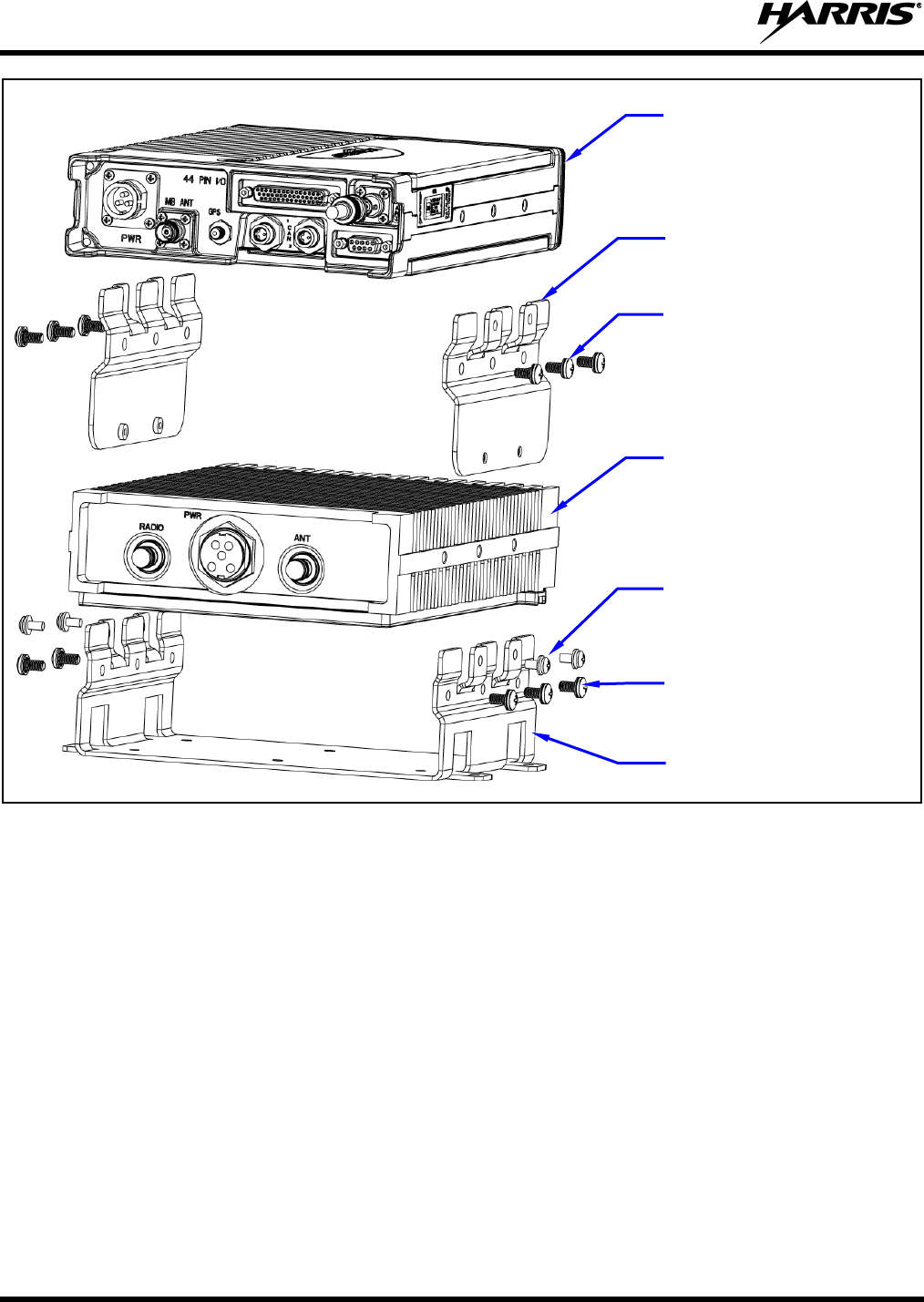
14221-1200-4010, Rev. B
38
Figure 7-4: Assembly into Stack Brackets (Exploded View)
To Mount LBPA and MRU in Separate Base Brackets:
Install the LBPA and the MRU into their individual base brackets using the following procedure. An
exploded view assembly diagram is shown in Figure 7-5.
1. Slide the mobile radio between the sides of Base Bracket FM103111V1. The connector of the radio
must face towards the cabling area of the radio installation.
2. Secure the radio into the bracket using six (6) M5 Philips-head screws (SC-018424), three (3) screws
per radio side.
These screws have a captive-type (SEMS) lock washer. Tighten all six (6) screws with a screwdriver
until the lock washer on each screw is fully compressed, and the radio is firm and flush between the
bracket sides.
3. Slide the LBPA into its Base Bracket 1000003678. The connector end of the LBPA must face
towards the cabling area of the installation.
MRU Radio
(XG-100M)
Low Band PA
(XG-100LPA)
Screw, M5 x 10mm
(SC-018424) 6x
Extension Bracket
(FM-018205)
Screw, M5 x 10mm
(SC-018424) 6x
Screw, #8-32
(AD00006) 4x
Base Bracket
(1000003678)
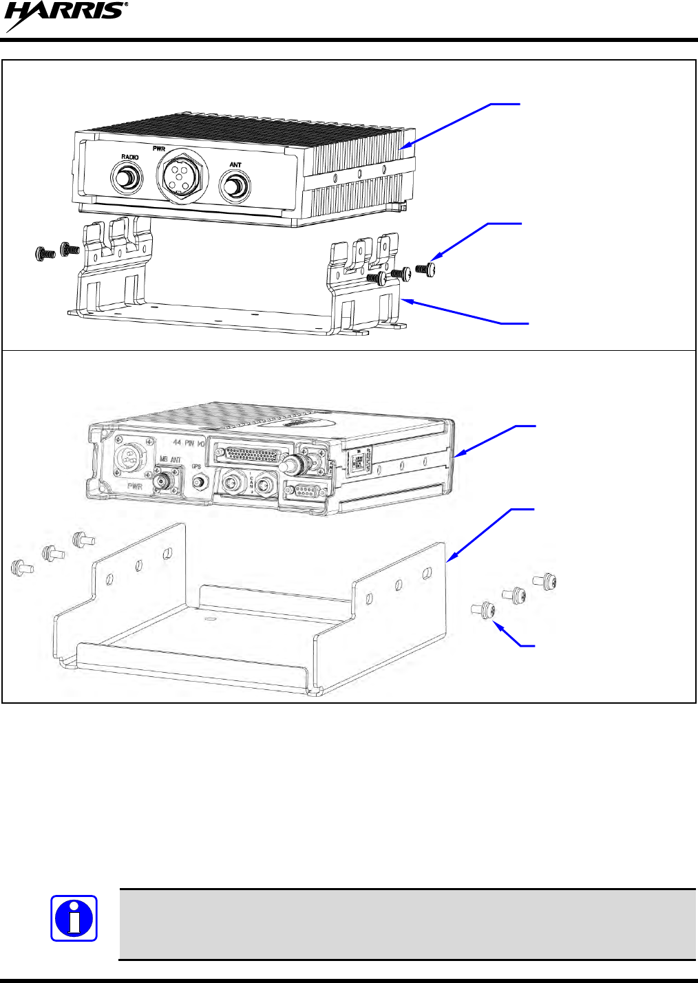
14221-1200-4010, Rev. B
39
XG-100LPA
XG-100M
Figure 7-5: Assembly into Separate Brackets (Exploded Views)
4. Secure the LBPA to the bracket using six (6) M5 Philips-head screws (SC-018424), three (3) per side.
These screws have a captive-type (SEMS) lock washer. Tighten all six (6) screws with a screwdriver
until the lock washer on each screw is fully compressed, and the LBPA is firm and flush between the
bracket sides.
5. Check the mounting area for proper clearance for cable service looping and for air circulation, plus an
area to secure and stow the excess cable lengths.
Proper mounting is one factor that ensures optimal radio performance. An improperly
mounted radio may experience degradation in the quality of voice and data
communications.
NOTE
MRU Radio
(XG-100M)
Low Band PA
(XG-100LPA)
Screw, M5 x 10mm
(Screw, flat washer, and
lock washer) 6x
Screw, M5 x 10mm
(SC-018424) 6x
Base Bracket
(FM103111V1)
Base Bracket
(1000003678)
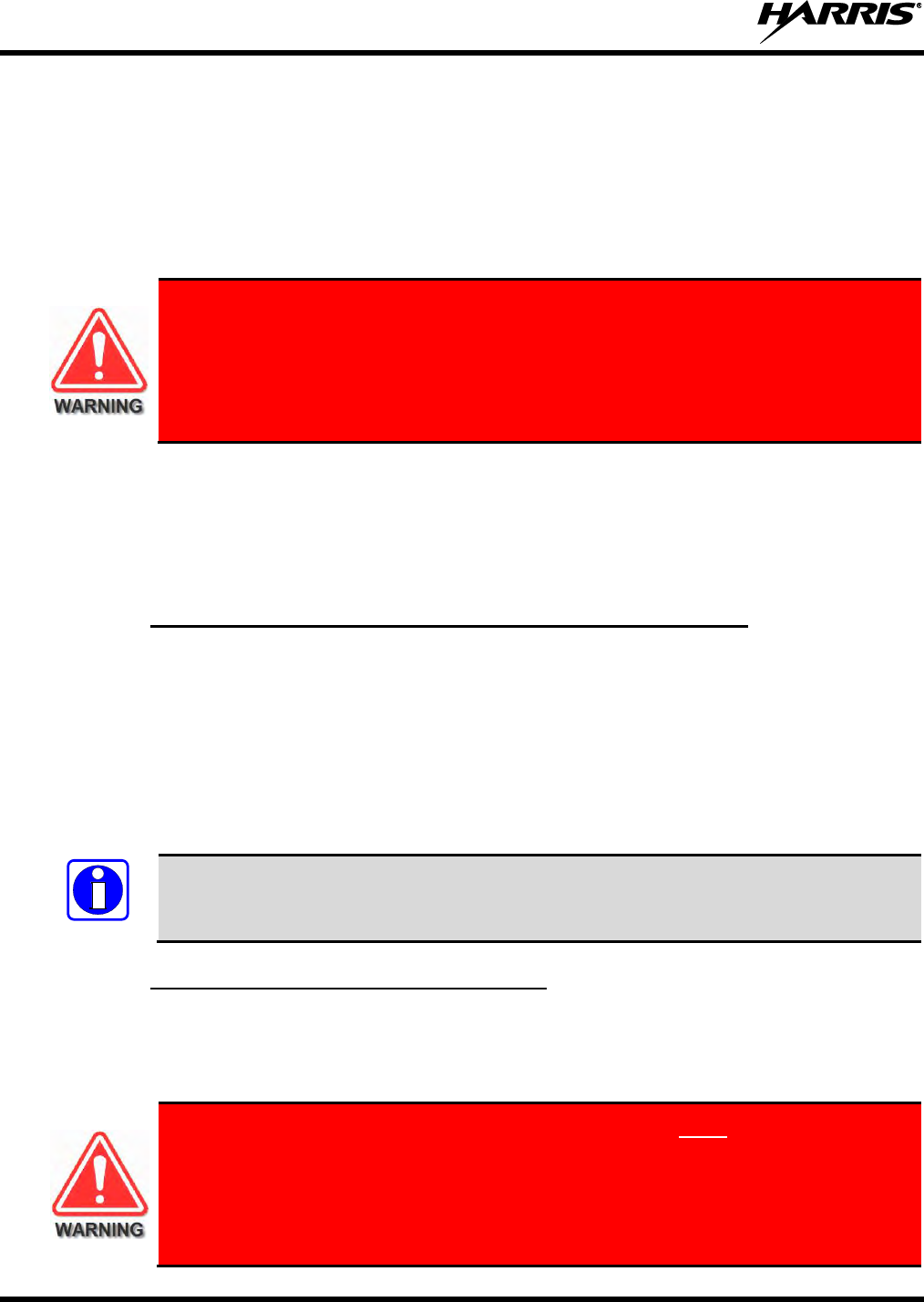
14221-1200-4010, Rev. B
40
8. ANTENNA INSTALLATION
8.1 ANTENNA MOUNTING LOCATIONS
For a standard motor vehicle, the MRU antenna must be installed at or near the center of the vehicle’s
rooftop, and the LBPA antenna must be installed in the center of the vehicle’s trunk lid.
At this time, review all information presented in the Regulatory and Safety section of
this manual (begins on page 7). Both transmit-receive antennas must be installed in
accordance with the guidelines presented. To reduce human exposure to radio
frequency (RF) electromagnetic energy during transmit mode, refer to Table 1-1 and
observe MPE data. During installation, refer to Figure 8-1 and Figure 8-2 to determine
the best possible antenna mounting locations.
Antennas must be mounted in locations on the vehicle as illustrated and described in this section. See
Table 5-5and Table 5-6 for antenna descriptions. Always follow manufacturer’s instructions when
mounting an antenna. References to locations through apply to the locations illustrated in Figure 8-1
and Figure 8-2. Minimum LBPA-to-MRU antenna separation distances as specified in these figures and
elsewhere in this manual must be maintained.
8.1.1 Direct Center or Center-Rear of Rooftop for MRU Antenna
The center of the vehicle’s roof is the best location for the MRU antenna (location ). For optimal
performance, the mounting area under the antenna must be flat with a minimum radius of six (6) inches of
metal ground plane. Locating the antenna directly in the center of the roof will minimize human exposure
to RF electromagnetic energy.
If obstructions such as a light bar or another antenna prevent the MRU antenna from being mounted in the
direct center of the roof, the antenna should be mounted a minimum of one foot away from and behind the
obstruction but in the middle of the roof with respect to the left and right sides of the vehicle (location ).
The two transmit and receive antennas must be at least three (3) feet (0.92 meters) apart. See
Figure 8-1 and Figure 8-2. The radio-end of each antenna cable must be labeled so each
cable is connected to the correct radio antenna connector.
8.1.2 Center of Trunk Lid for LBPA Antenna
For a standard motor vehicle, the LBPA antenna should be located in the center of the vehicle’s trunk lid
(location ). Locating the antenna directly in the center of the lid will provide the best coverage, and
minimize human exposure to RF electromagnetic energy.
The antenna cable of Harris-approved antennas should never be cut to a shorter
length. Instead, excess cable must be tied and stowed. This not only prevents the
antenna from radiating above its intended or configured power, but it also allows for
future installation considerations such as a relocation of the mobile radio within the
vehicle. Installations requiring longer cables are to be treated as custom and
separately specified.
NOTE
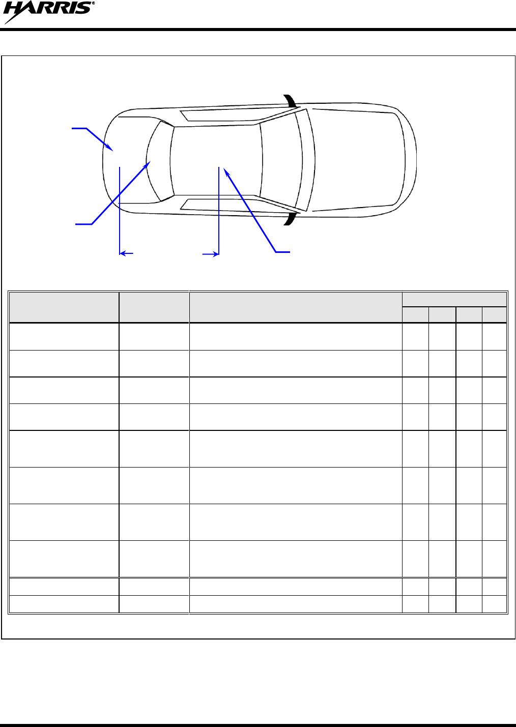
14221-1200-4010, Rev. B
41
TOP VIEW OF A TYPICAL VEHICLE
ANTENNA
PART NUMBER
FOR
RADIO
ANTENNA DESCRIPTION *
LOCATION
AN-125001-002 (mount) with
12099-0310-01 (element)
XG-100M
136-174/380-520/762-870 MHz Standard Rooftop-
Mount with Multi-Band 0 dBd Gain Antenna Element
AN-125001-004 (mount) with
12099-0310-01 (element)
XG-100M
136-174/380-520/762-870 MHz Thick Rooftop-Mount
with Multi-Band 0 dBd Gain Antenna Element
AN-125001-006 (mount) with
12099-0310-01 (element)
XG-100M
136-174/380-520/762-870 MHz GPS Combo Rooftop-
Mount with Multi-Band 0 dBd Gain Antenna Element
AN-125001-008 (mount) with
12099-0310-01 (element)
XG-100M
136-174/380-520/762-870 MHz Standard Magnetic-
Mount with Multi-Band 0 dBd Gain Antenna Element
AN-125001-002 (mount) with
12099-0330-01 (element)
XG-100M
136-174/380-520/762-870 MHz Standard Rooftop-
Mount with Multi-Band Antenna Element
(6 dBi from 762 to 870 MHz)
AN-125001-004 (mount) with
12099-0330-01 (element)
XG-100M
136-174/380-520/762-870 MHz Thick Rooftop-Mount
with Multi-Band Antenna Element
(6 dBi from 762 to 870 MHz)
AN-125001-006 (mount) with
12099-0330-01 (element)
XG-100M
136-174/380-520/762-870 MHz GPS Combo Rooftop-
Mount with Multi-Band 0 dBd Gain Antenna Element
(6 dBi from 762 to 870 MHz)
AN-125001-008 (mount) with
12099-0330-01 (element)
XG-100M
136-174/380-520/762-870 MHz Standard Magnetic-
Mount with Multi-Band 0 dBd Gain Antenna Element
(6 dBi from 762 to 870 MHz)
AN-025187-001
XG-100M
GPS Receive Only, Roof-Mount
AN-025187-003
XG-100M
GPS Receive Only, Magnetic-Mount
* See Table 5-6 which begins on page 28 for the detailed descriptions.
Figure 8-1: Required Unity mobile MRU Antenna Mounting Location with Antenna Part Numbers
Trunk Lid
Rooftop
Hood
3-Feet Minimum Antenna
Separation
LBPA
Antenna
GPS Antenna
(if required;
see text)
MRU Antenna — Use location (center-most
location). See text.
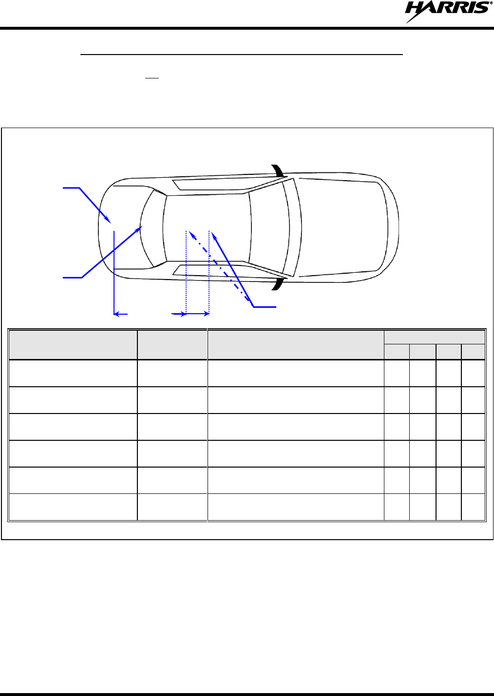
14221-1200-4010, Rev. B
42
8.1.3 Rear Deck Lid for GPS Stand-Alone GPS Receive Antenna
If the Unity mobile does not use a GPS combination-type antenna and it is equipped with a GPS receiver,
a stand-alone GPS receive antenna must be separately located and mounted. The vehicle’s rear deck lid
(location ) is the recommended mounting location for this case. This locates the GPS antenna inside the
vehicle.
TOP VIEW OF A TYPICAL VEHICLE
ANTENNA
PART NUMBER
FOR RADIOS
ANTENNA DESCRIPTION *
LOCATION
AN-125001-002 (mount) with
AN-025127-101 (element)
XG-100LPA
Low Band Mobile Antenna 30–35 MHz
NMO
AN-125001-002 (mount) with
AN-025127-102 (element)
XG-100LPA
Low Band Mobile Antenna 34–37 MHz
NMO
AN-125001-002 (mount) with
AN-025127-103 (element)
XG-100LPA
Low Band Mobile Antenna 37–40 MHz
NMO
AN-125001-002 (mount) with
AN-025127-104 (element)
XG-100LPA
Low Band Mobile Antenna 40–47 MHz
NMO
AN-125001-002 (mount) with
AN-025127-105 (element)
XG-100LPA
Low Band Mobile Antenna 45–48 MHz
NMO
AN-125001-002 (mount) with
AN-025127-106 (element)
XG-100LPA
Low Band Mobile Antenna 47–50 MHz
NMO
* See Table 5-5 which begins on page 28 for the detailed descriptions.
Figure 8-2: Required LBPA Antenna Mounting Location with Antenna Part Numbers
Trunk Lid
Rooftop
Hood
3-Feet
Minimum
Antenna
Separation
GPS Antenna
(if required;
see text)
MRU Antenna
LBPA
Antenna
14221-1200-4010, Rev. B
43
8.2 ANTENNA INSTALLATION PROCEDURES
Antennas must be installed before completing the radio installation.
8.2.1 Installing NMO Antenna Mounts AN-125001-001, -002, -003 and -004
These NMO style antenna mounts can each be used with several different antenna elements. Only limited
access under the mounting location is typically required. The installation procedure is presented in
Section 8.2.1.3.
8.2.1.1 Standard NMO Antenna Mounts AN-125001-001 and AN-125001-002
These standard ¾-inch NMO antenna mounts require a ¾-inch hole in a relatively flat area of the vehicle
body, with a vehicle metal thickness of between 0.020 and 0.040 inches. AN-125001-002 has a very-low-
loss coax cable (LMR-195 or equivalent).
8.2.1.2 Thick-Roof NMO Antenna Mounts AN-125001-003 and AN-125001-004
Both of these thick-roof NMO antenna mounts use either a ⅜-inch or a ¾-inch mounting hole in a
relatively flat area of the vehicle body, with a vehicle metal thickness of between 0.040 and 0.1875 inches
(3/16-inch maximum thickness). AN-125001-004 has a very-low-loss coax cable (LMR-195 or equivalent).
For thick-roof NMO antenna mounts AN-125001-003 or AN-125001-004, using a ⅜-inch
mounting hole will require better access to the underside of the mounting location than if a
¾-inch hole is used. This is because, in the case of a ⅜-inch hole, the antenna mount’s
bushing assembly must be inserted from the underside of the mounting surface.
When using a ¾-inch mounting hole to mount thick-roof NMO antenna mounts
AN-125001-003 or AN-125001-004, the thickness of the mounting surface must be at least
⅛-inch (0.125-inch minimum thickness). This requirement is due to the thickness of the
alignment ring used to center the bushing assembly within the ¾-inch mounting hole.
8.2.1.3 Installation Procedure for Mounts AN-125001-001 through -004
1. Select the antenna mounting location in accordance with the information presented in Sections 1 and
8.1 of this manual. If necessary, contact the Technical Assistance Center for assistance. See page 21
for TAC contact information.
2. Verify no obstructions exist immediately below the respective mounting location on the underside of
the vehicle body, such as vehicle ribbing/body framing, a wiring harness, air bag equipment, etc. Also
verify there is a sufficient access path and clearance for the mount’s coax cable. If there is an
obstruction or insufficient clearance, select another nearby mounting location.
3. Measure and mark the center point of the selected antenna mounting location. Be sure to center the
mark from side-to-side of the vehicle.
NOTE
NOTE
14221-1200-4010, Rev. B
44
4. Obtain a hole saw specifically designed for drilling NMO mounting holes of the required diameter.
(e.g., Antenex/Laird Technologies model HS34 or equivalent for a ¾-inch hole; Antenex/Laird
Technologies model HS38 or equivalent for a ⅜-inch hole).
5. If the vehicle’s headliner panel, carpet, seats, or otherwise, is below the mounting location, move or
remove the headliner panel, etc. as necessary to protect it. Alternately, apply a heat-resistant mask
material (such as a fiberglass mat or thin sheet metal with masked edges) as required to “catch” the
metal shavings and the metal plug (if any) produced by the hole saw. The plug (if any) may be
relatively hot if/when it drops out of the saw upon completion of the hole drilling process. ⅜-inch
diameter hole saws generally produce only shavings, not plugs.
6. Using the hole saw and a drill, drill a hole at the marked hole center point. Position the drill square to
(i.e., 90 degrees from) the vehicle mounting surface so paint immediately outside of the perimeter of
the hole is evenly removed.
Excessive use of the hole saw and/or failure to position the drill square with (i.e., at a
90-degree angle from) the vehicle mounting surface may result in damage to the metal
mounting surface, in the area immediately outside of the perimeter of the hole.
7. Ensure the saw removed the paint immediately around the hole as the drilling operation completes. If
not, do so by reinserting the saw completely into the hole and spinning it as required. This allows
proper grounding via the mount’s lock nut on the top of the mounting surface. On the bottom of the
mounting surface, the “teeth” of the mount’s bushing assembly may not provide a good ground due to
thick vehicle undercoating, thick primer, oxidation/rust, etc.
8. For a ¾-inch hole, feed the unterminated end of the mount’s coax cable into the hole from the top
surface of the vehicle until the mount’s bushing assembly is in position to drop into the hole. The
bushing should be tilted at a slight angle and fed into the hole. The threaded shank of the mount’s
bushing assembly will not fall through a ¾-inch hole.
9. For a ⅜-inch hole, feed the threaded shank of the mount’s bushing assembly into the hole from the
underside of the mounting surface. Hold it into position until the lock nut is installed.
10. If installing a thick-roof antenna mount (⅜-inch shank) into a ¾-inch hole, place the alignment ring
onto the threaded shank of the mount. This ring has an approximate ¾-inch outside diameter.
11. A tube of synthetic lubricant is included with the antenna mount. Apply this lubricant to the mount’s
rubber O-ring. Do not get any lubricant on the center contact of the mount’s bushing assembly.
12. As illustrated in Figure 8-3 and Figure 8-4, add the O-ring (C) and lock nut (D) to the top of the
mount’s bushing assembly (A). With the O-ring in the groove in the underside of the lock nut, thread
the lock nut onto the bushing assembly. Be sure the O-ring remains in the groove before tightening
the lock nut.
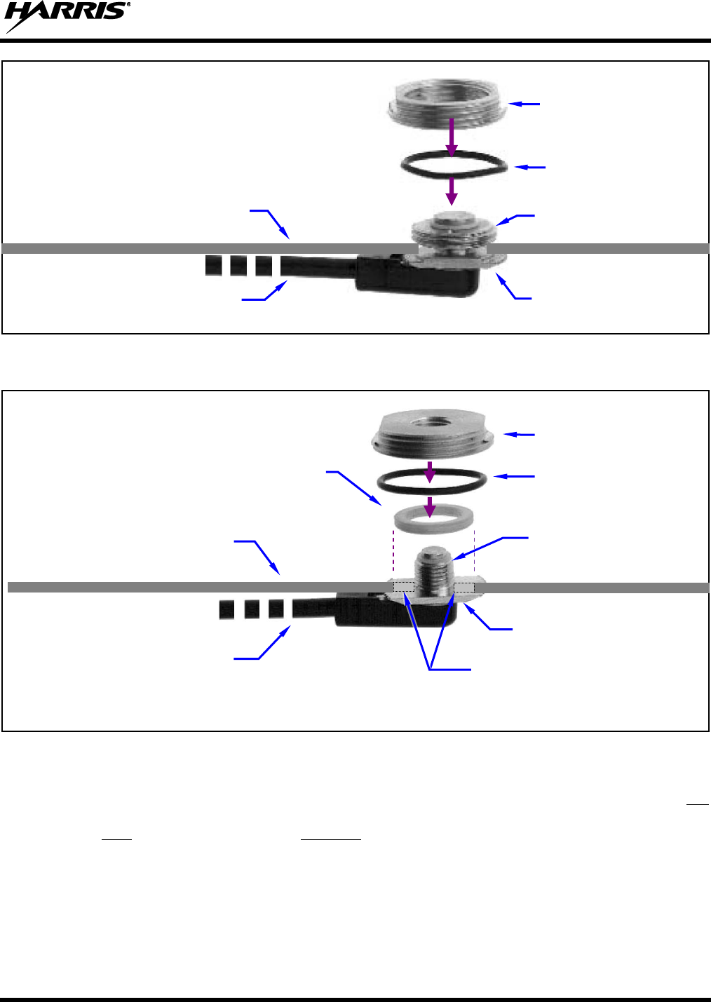
14221-1200-4010, Rev. B
45
Figure 8-3: Installing a Standard ¾-Inch NMO Antenna Mount
(e.g., AN-125001-001 or AN-125001-002)
Figure 8-4: Installing a Thick-Roof NMO Antenna Mount
(e.g., AN-125001-003 or AN-125001-004)
13. Using a 15/16-inch open-end wrench, tighten the lock nut until it fully compresses the O-ring and
makes good contact with the vehicle mounting surface. The groove’s ridges on the bottom of the lock
nut must make full contact with the unpainted metal surface of the vehicle.
14. Install the antenna element per the procedure in Section 8.2.4.
Coax Cable (Partial)
Rubber O-Ring (C)
Vehicle Mounting Surface
(top side)
Bushing Assembly (A)
Lock Nut (D)
Threaded Shank (B)
Coax Cable (Partial)
Vehicle Mounting Surface
(top side)
Bushing Assembly (A)
Alignment Ring
(Used only with ¾-inch mounting hole)
Rubber O-Ring (C)
Lock Nut (D)
Threaded Shank (B)
(Extensions shown to illustrate a
⅜-Inch hole vs. a ¾-inch hole.)
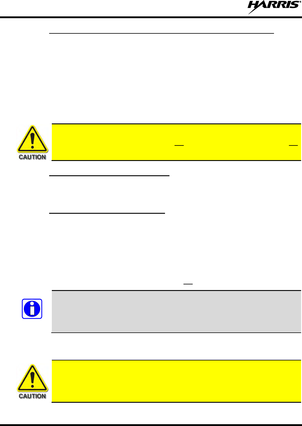
14221-1200-4010, Rev. B
46
8.2.2 Installing NMO Magnetic Antenna Mounts AN-125001-007 and -008
Thoroughly clean the bottom of the magnetic mount and the selected vehicle mounting surface by
removing all dust, dirt, etc.
Carefully place the magnet mount onto the metal surface of the vehicle at the selected location. The coax
cable exiting the mount’s base should be orientated towards the point at which it will enter into the
interior of the vehicle. Do not try to reposition it by sliding it on a painted metal surface.
Route the mount’s coax cable to the radio location, passing it by the trunk lid’s perimeter gasket, door
perimeter gasket, etc., as necessary.
Install the antenna element per the procedure in Section 8.2.4.
To remove a magnetic antenna mount, hold it at the bottom of its base and tilt it at an angle
to release the magnetic attraction force. Do not pull on the mount’s coax cable. Do not
drag the mount across the mounting surface.
8.2.3 Installing all Other Antenna Mounts
For any other type of antenna mount not covered in the previous sections, such as GPS combination
antennas, install the mount in accordance with the installation instructions included with the mount.
8.2.4 Attaching NMO Antenna Elements
1. Clean the top surface of the NMO mount and the surface of the vehicle immediately around the
mount.
2. Place the gasket included with the antenna element (not pictured in Figure 8-3 or Figure 8-4) around
the mount and against the surface of the vehicle. If a lubricant or sealant was included with the
gasket, apply it to the gasket before placing the gasket.
3. Apply the antenna element to the top of the mount and tighten it in a clock-wise direction (as viewing
from the top). Use an appropriate wrench if required. Do not over-tighten.
If the mobile radio installation employs a ¼-wave unity-gain antenna (part number
AN102800V1 or AN-225006-001), the antenna element must be trimmed to the proper
length in order to minimize antenna system Voltage Standing-Wave Ratio (VSWR). Refer
to Figure 8-5 on page 47 and/or the instructions included with the antenna for trimming
instructions.
4. Install a placard (not supplied) on the vehicle’s dash panel, in accordance with the following
CAUTION. Place the placard in plain view of the vehicle operator’s position.
Before entering any automatic vehicle (“car”) wash equipment, remove the antenna
elements from the antenna mounts, and secure the elements in a safe location inside the
vehicle. This will prevent the wash equipment from damaging the elements and/or mounts.
After exiting the wash equipment, thoroughly dry the top of the mount before re-installing
the elements.
5. Continue with the connection procedure presented in the next section.
NOTE
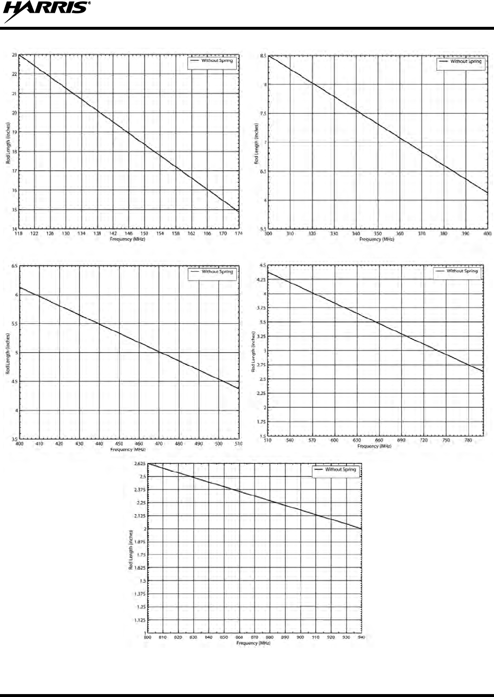
14221-1200-4010, Rev. B
47
Figure 8-5: Cutting Charts for Antenna Element AN-225006-001
14221-1200-4010, Rev. B
48
8.2.5 Connecting the Mobile Antennas
1. Label the radio-end of each antenna cable. The cable from the rooftop-mounted antenna (highest of
the two) should be labeled “MRU Antenna” and the cable from the trunk-mounted antenna (lowest of
the two) should be labeled “LBPA Antenna.”
2. Route each antenna cable from the antenna to the rear of the respective radio. Remove headliner
panel, other interior panels, etc., as necessary. Keep each cable out of casual contact areas from
persons within the vehicle. Tie and stow as necessary to protect the cables.
Use the full length of coaxial cable included with each antenna. Never cut the cable to a
shorter length, but rather coil any excess. Reducing the length of cable increases the
output power radiated by the antenna, thereby exceeding the Maximum Permissible
Exposure (MPE) allowance regulated by the FCC.
The MRU and LBPA antennas are not interchangeable. Therefore, label the radio-end
of each cable for future reference, as described in step 1.
3. Using an appropriate crimp tool, crimp the supplied TNC RF connector to the end of each antenna
cable. See Figure 8-6 for crimping instructions.
(VS-AN-025167-010 Rev. A)
Figure 8-6: Crimping Instructions for TNC RF Connector (Dimensions in Inches)
4. Connect each antenna cable’s TNC plug-type (male) connector to the respective radio’s TNC
receptacle-type (female) RF connector at the rear of the radio. The MRU antenna cable (labeled
“MRU Antenna”) must be connected to the “MB ANT” connector on the rear of the radio. The LBPA

14221-1200-4010, Rev. B
49
antenna cable (labeled “LBPA Antenna”) must be connected to the “ANTENNA” connector on the
LBPA. Mate the connectors and turn the plug clockwise until finger-tight.
This will be a temporary connection until the radios and antennas can be tested after the installation is
complete (in accordance with test procedures presented in Section 17). The antennas should be connected
now in case of accidental transmission.
8.2.6 Connect RF Cable between Unity Mobile MRU and Low Band PA
As shown in the rear view of Figure 6-4 (page 32), an RF cable must be connected between the mobile
radio (MRU) and the Low Band Power Amplifier. Obtain and connect this cable as follows:
1. Get the RF Cable W90-0223-001 from the XM-ZN2G installation kit (refer to Table 5-2 on page 23).
2. Connect one end of the cable to the MRU’s Low Band BNC connector labeled “LB ANT.”
3. Connect the other end of the cable to the Low Band Power Amplifier BNC connector labeled
“RADIO.”
4. Ensure both BNC connectors are secure.
14221-1200-4010, Rev. B
50
9. DC POWER INSTALLATION
Refer to the wiring diagram at the end of this manual as necessary when performing the
wiring procedures presented in this section.
9.1 OVERVIEW OF ON/OFF POWER WIRING CONFIGURATIONS
Radio on/off power control is accomplished by the control head. When the control head is turned on, it
“wakes-up” the MRU via data activity on the CAN link. The MRU automatically powers-up the LBPA
when the MRU is powered on. The following power wiring configurations are supported:
Any DC input power provided to the radio shall be no higher or lower than
13.6 volts DC 10%. The DC input power should be free and clear of any AC noise or DC
spikes above 18 volts. If the vehicle cannot meet these requirements, then DC conditioning
will be required before any DC power is connected to the radio. This includes conditioning
for both the radio’s main DC power input lead and for its switched ignition sense power
input. DC conditioning can be accomplished by a noise filter or DC isolation equipment
such as Harris part number FL-018314-001 or FL-018314-002, or similar units with equal
specifications. The fuse must be placed in-line before any noise filter. Contact TAC for
additional information.
Radio turns on and off automatically with vehicle’s ignition switch/key — This configuration
allows the on/off state of the vehicle’s ignition switch/key to control the on/off power state of the
radio. The white wire of the control head’s DC Power Cable is connected to a fused switched power
source, typically identified as vehicle “Accessory” power. This source must switch on (up to positive
(+) battery voltage potential) when the vehicle’s ignition switch/key turns on, and it must switch off
(to near zero volts) when the ignition switch/key turns off. The required fuse rating is 3 amperes.
When using this configuration, the control head’s on/off/volume control must be left in the on
position for automatic power-up/down to function properly.
Radio turns on and off with a manual switch — This configuration is used when, for example, the
radio must remain on even when the ignition key must be removed from the vehicle and a separate
on/off switch is acceptable. The white wire of the control head’s DC Power Cable is connected to one
side of a manually-controlled switch, and the other side of this switch is connected to unswitched and
fused vehicle power. The required fuse rating is 3 amperes. When using this configuration, the control
head’s on/off/volume control must be left in the on position for automatic power-up/down to function
properly.
Radio turns on with control head’s on/off/volume control (“hot wired”) — This configuration
allows radio on/off power control only via the control head’s on/off/volume control. It may be desired
if, for example, the radio must remain on even when the ignition key must be removed from the
vehicle and a separate on/off switch is not desired and/or not acceptable. The white wire of the
control head’s DC Power Cable must be connected to unswitched and fused vehicle power. The
required fuse rating is 3 amperes.
NOTE
14221-1200-4010, Rev. B
51
The MRU, the LBPA, and the control head require separately-fused main DC power. This is the red wire
of each DC power cable. The switch power source to the control head is also separately fused. This is the
white wire of the control head’s DC power cable. In-line type fuses and fuse holders are utilized.
9.2 POWER INSTALLATION PROCEDURE
9.2.1 Radios DC Power Cables and Main Fuse Holders Installation
Each radio’s DC power cable has a connector which mates to the radio’s power cable, a 20-foot red wire
for the main power connection, a 20-foot white wire which is not used/not connected in this application,
and a 4-foot black wire for the ground connection.
Cable CA-012365-001 is used with the XG-100M and has a 3-pin connector. It is supplied with HFB-type
waterproof fuse holders, two AGC-type fuses, and non-insulated ring terminals.
Cable 14002-0167-01 is used with the XG-100LPA and has a 5-pin connector. It is supplied with an
HEB-type water-resistant fuse holder, heat shrink tubing, a BAF-type 30-amp fuse, and non-insulated ring
terminals.
The following installation procedures are recommended:
9.2.1.1 Black Wire Connections (Ground Wires)
1. Connect the radio’s DC Power Cable to the MRU by mating its connector to the radio’s 3-pin DC
power cable connector. Visually align the key and firmly push and turn the outer locking ring
clockwise until it stops. A click will be sensed to confirm proper mating.
Do not confuse the radio’s DC Power Cable which has a 6 or 10-AWG red wire with the
control head’s DC Power Cable which has a 12-AWG red wire. A radio requires more DC
operating current than the control head, and therefore, larger-gauge power wires (of 6 or
10-AWG). For a radio, the DC Power Cable’s part number is CA-012365-001 (has
10-AWG red wire). For the LBPA, the DC Power Cable’s part number is 14002-0167-
01 (has 6-AWG red wire). Control head DC Power Cable installation procedures are
provided in Section 10 of this manual.
2. Connect the other DC Power Cable to the LBPA using the same connection method.
3. Prepare to connect both cables’ black wires to vehicle ground by locating an area of vehicle metal
within approximately three (3) feet of the two units. This surface must have a solid and stable
connection to vehicle ground (i.e., battery ground).
14221-1200-4010, Rev. B
52
The radios must have a solid and stable ground connection to vehicle ground. If there
is no well-grounded metal surface within approximately three (3) feet of the radios, a
metal grounding strap or a heavy-gauge wire (with proper wire terminals) must be
added between the metal surface and a solid and stable vehicle grounding point,
preferably near the battery. Some vehicles are equipped with a high-current DC
power access point (a vehicle option) that provides high-current power and ground
studs, typically in the vehicle’s trunk area. In this case, the ground stud of the power
access point can be considered a good vehicle ground, and used as such. Metal surfaces
should be stripped of all paint and dirt to expose bare metal before attaching a
grounding strap or wire terminal. To make all ground connections, the use of
stainless-steel hardware with machine-screw threads, shelf-locking nuts, and washers
is recommended.
4. Strip the area of any paint or dirt to expose a bare metal surface, approximately ¾-inch square.
5. Drill a hole in the approximate center of the bare metal surface, and deburr it.
A ⅜-inch non-insulated ring terminal is supplied with each cable to make the ground connection.
Therefore, hole diameter should be appropriate for the utilized grounding screw/bolt size and type
used to connect the ring terminals to the bare metal surface. This hardware is not supplied.
6. Cut the two (2) black wires to the required length plus some additional length for service loops in
each wire, then strip insulation back approximately ¼-inch.
7. Crimp a ⅜-inch non-insulated ring terminal (supplied with the cable) to the end of each black wire.
8. Attach the two (2) ring terminals with black wires to the bare metal surface using stainless-steel self-
locking hardware (i.e., machine screws with washers and locking nuts) or other appropriate hardware
to ensure a reliable terminal-to-metal contact. Tighten securely.
9. Apply an approved paint or rust-inhibitor over the remaining exposed bare metal surface and around
the ring terminal. Do not use an acid-based sealant.
9.2.1.2 Red Wires, Main Fuse Holder Connections (Radios’ Main Power Wires) and
CAN Cable
In a typical vehicle installation, the majority of the CAN cable between the remote-mount MRU radio and
the control head can be routed through the vehicle along with the two red wires of the radios’ DC power
cables. This is a time-saving measure. Also, any necessary option/accessory cables from the back of the
radio can also be routed with these wires and cable within the vehicle’s interior (i.e., up to but not through
the vehicle’s firewall).
The following installation procedure is recommended:
1. From the installation kit, get the CAN cable, part number CA-009562-030.
2. Remove interior panels, door kick panels, etc., as necessary to route the two red wires and the CAN
cable from the area of the remote-mount MRU radio (typically near the rear of the vehicle) to an area
near the vehicle’s firewall.
14221-1200-4010, Rev. B
53
3. Route the red wire and the CAN cable through existing channels in the vehicle body to an area near
the vehicle’s firewall. Leave service loops at the rear of the radio. CAN cable installation is
completed later using the control head installation procedure (Section 10.5).
4. Continue installation of two (2) DC Power Cables by routing their 20-foot red wires to the location of
the vehicle’s battery (or its main DC bus bar or stud). Route the wires through channels in the vehicle
to the location of the battery. Protect the wires from possible chafing where necessary. Tie and stow it
as necessary.
Plan the routing of the two red wires carefully, using an existing access hole in the vehicle’s
firewall if possible. Alternately, drill a new hole approximately 3/8-inch in diameter and
install a small rubber grommet to protect the wires from chafing on the hole’s sharp metal
edge. To prevent fumes from entering the passenger compartment, this
hole/grommet/wire combination must also be sealed with a silicon-based sealer before
completing the installation.
Do not install any wiring or fuse holder over or in the near vicinity of the vehicle’s engine.
Excessive engine heat can cause permanent damage to these components and can lead to
intermittent electrical connection to the battery.
The white wire of both units’ DC Power Cables requires no electrical connection. Rather
than be cut from the two cables, it is recommended that these wires be routed up to the
vehicle’s fuse box, coiled, labeled, and stowed for possible future use. The white wire of the
control head’s DC Power Cable is the radio installation’s ignition sense input for on/off
power control of both the control head and radio. Radio on/off power control is
accomplished by the control head. The control head “wakes-up” the MRU radio via data
activity on the CAN link.
5. Get the two (2) inline fuse holders included with the DC Power Cables.
6. Observe and abide by the following WARNING!
Before making connections to the battery’s positive post, carefully disconnect the
battery’s negative (ground) cable(s). This will prevent tools or other metallic objects
which come in contact with the battery’s positive terminal from shorting to vehicle
ground, causing sparks or even a fire or an explosion!
When disconnecting the negative cable(s), cover/insulate the positive post(s) so a tool
cannot short between the posts. Some vehicles, such as those with diesel engines have
more than one battery; in this case, disconnect the negative cables at all batteries.
Radio and control head fuses should not be installed until all wiring is complete. This
will prevent the radio from powering up prematurely and/or causing an in-rush of
current that could lead to shorting of the battery, sparks, or even fire.
7. Cut the red wires to the required lengths for connection to the battery’s positive (+) battery terminal
(or the main DC bus bar or stud).
NOTE
14221-1200-4010, Rev. B
54
8. Prepare to splice the two (2) inline fuse holders into the red wires by cutting the red wires again, at
approximately three (3) to six (6) inches from each end.
9. Strip all wire ends back approximately ⅜-inch each.
10. For the HFB-type waterproof fuse holder used with the MRU, place a fuse holder shell on each wire
so each large end of the shell is towards the wire end, then add a fuse holder terminal onto the
stripped portion of the wire end.
11. For the HEB-type water-resistant fuse holder used with the LBPA, four (4) short pieces of heat shrink
tubing are included with the fuse holder for insulating crimped fuse holder terminals.
Place a piece of this tubing onto each 6-AWG red wire before crimping the wire end to the fuse
holder terminal. Two pieces of tubing at each crimped terminal may be used, if necessary. Next,
observe line/load labeling on the fuse holder and place the correct side of the holder (with terminal)
onto a stripped wire end.
12. Securely crimp each fuse holder terminal to the wire end.
13. For the HEB-type water-resistant fuse holder used with the LBPA, continue by shrinking the heat
shrink tubing(s) over each crimped terminal. No metal of a crimped terminal should be exposed after
completing each fuse holder-to-red wire connection.
14. Label each fuse holder and red wire appropriately (e.g., “MRU: 15-AMP FUSE” and “LBPA:
30-AMP FUSE”).
Do NOT install fuses into the fuse holders at this time.
15. Crimp an appropriate electrical terminal to each short red wire. A ⅜-inch ring terminal is included
with each cable for this purpose, but another terminal type (not supplied) may be used if required.
16. Connect both ring terminals directly to the battery’s positive post, or if present, to a stud on the
battery’s main/non-switched power distribution terminal block.

14221-1200-4010, Rev. B
55
10. CONTROL HEAD INSTALLATION
The remote-mount Unity XG-100M mobile radio must be connected to a control head to provide the
operator-to-radio interface. Two (2) different control heads are available — the CH-100 control head and
the CH-721 System model control head. See Figure 10-1 through Figure 10-4 respectively. A control
head is interfaced to the radio via a CAN cable. Each control head is powered and fused by an individual
DC power cable (i.e., the control head is powered separately from the radio).
10.1 SELECTING THE MOUNTING LOCATION
When selecting a location for the control head, first observe the safety and operator-convenience related
information presented in Section 6.1 on page 29. Always consider and include clearance for the
microphone’s connector that must mate to the mic connector on the front panel of the head, and clearance
for the connectors/cables that must mate to the connectors on the rear panel of the head. The control head
can be mounted under or on top of a mounting surface (typically the vehicle’s dash) as space permits
using the standard U-shaped mounting bracket.
The size and weight of the control head necessitate less stringent mounting requirements than the radio.
However, like the radio, the control head must be mounted to a mechanically-rigid surface. The control
head must not vibrate when the vehicle is in motion and it must remain stable during normal operations
by an operator (i.e., button presses, knob rotation, excessive tugs on the mic cord, etc.). If the control head
is mounted to a plastic dash panel, either fender washers or a field-fabricated metal backing plate should
be used to mount the head’s bracket to the plastic dash panel.
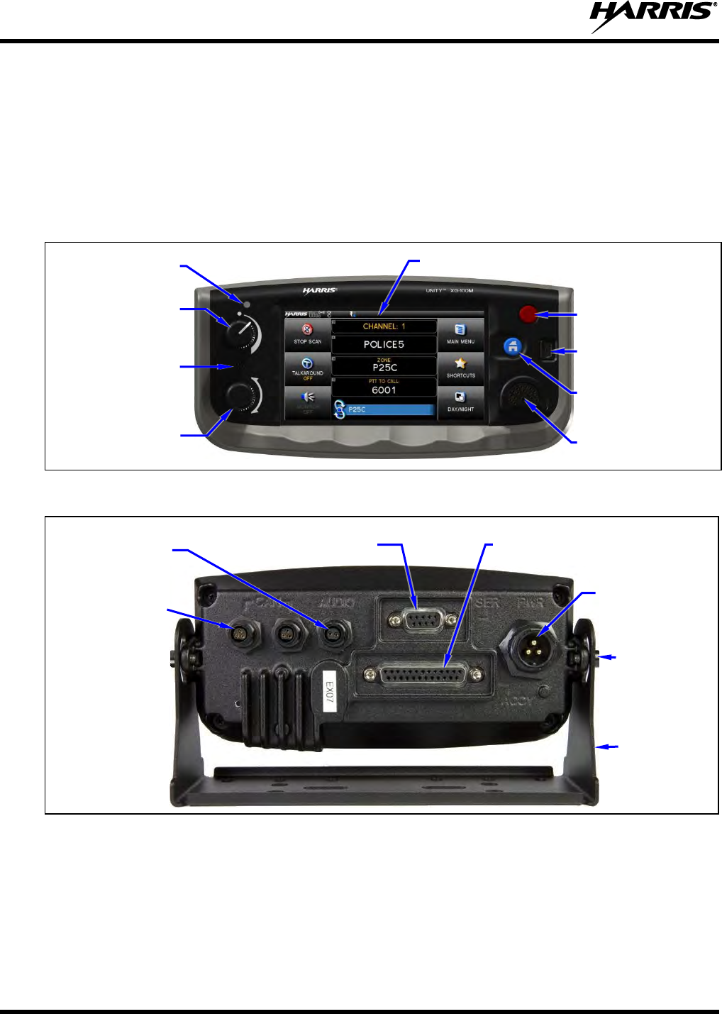
14221-1200-4010, Rev. B
56
10.2 GENERAL INFORMATION ON THE CH-100 CONTROL HEAD
The CH-100 control head features a 4.3-inch touchscreen high-contrast sunlight-readable LCD color
display, providing an easy-to-use menu-driven operator interface. This head also features a Bluetooth®
wireless interface for connection of optional equipment and to support radio and control head
programming via a wireless connection. The front panel of the CH-100 head also features an easy-to-use
on/off/volume control and group/channel selection controls, an emergency button, a home button, a USB
programming port, a transmit/receive busy indicator, and a microphone connector.
Figure 10-1: CH-100 Control Head Front Panel
Figure 10-2: CH-100 Control Head Rear Panel (shown with Standard Mounting Bracket)
The CH-100 control head’s mounting bracket allows pitch-axis (tilt) positioning for best viewing angle.
Pitch adjustments are accomplished by loosening thumbscrews on each side of the bracket, changing the
pitch/tilt of the head as needed, and then retightening the thumbscrews. A 150-degree pitch/tilt angle is
provided.
On/Off/Volume
Control
System/Group/-
Channel Selection
Control
Ambient Light
Level Sensor
4.3-Inch LCD Touchscreen Color Display
Emergency Button
Home Button
USB Programming
Port
Microphone
Connector
CAN Port
Connectors
(2 places)
Speaker Audio
Connector
Serial Port Connector
(Female DB-9)
DC Power
Connector
Accessory Connector
(Female DB-25)
Socket-
Head Cap
Screws
(2 places)
Standard
Mounting
Bracket
Note: Serial Port
and Accessory
connectors
are shown without
waterproof covers.
Built-In
Microphone for
Noise-
Suppression
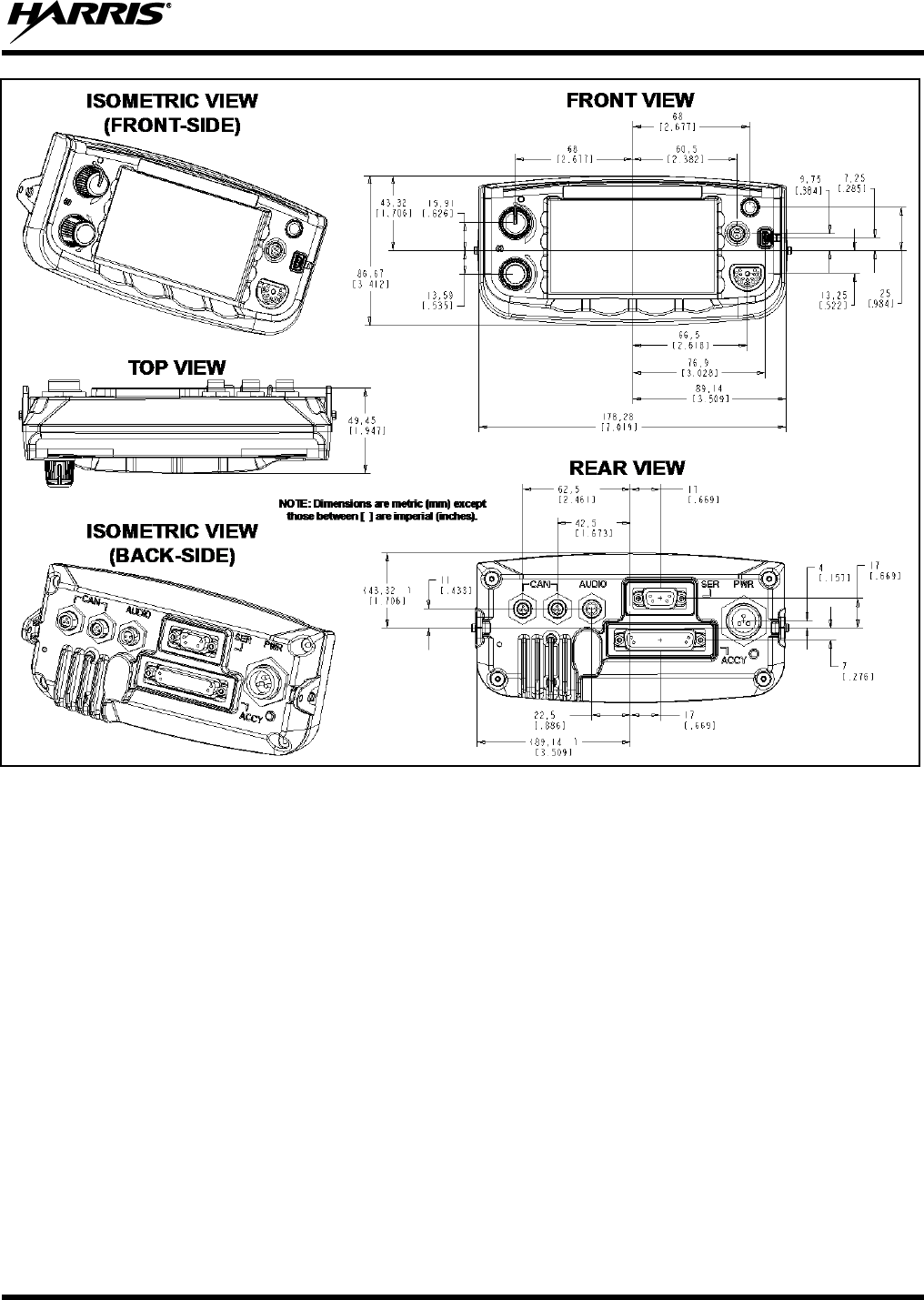
14221-1200-4010, Rev. B
57
Figure 10-3: CH-100 Control Head Dimensions
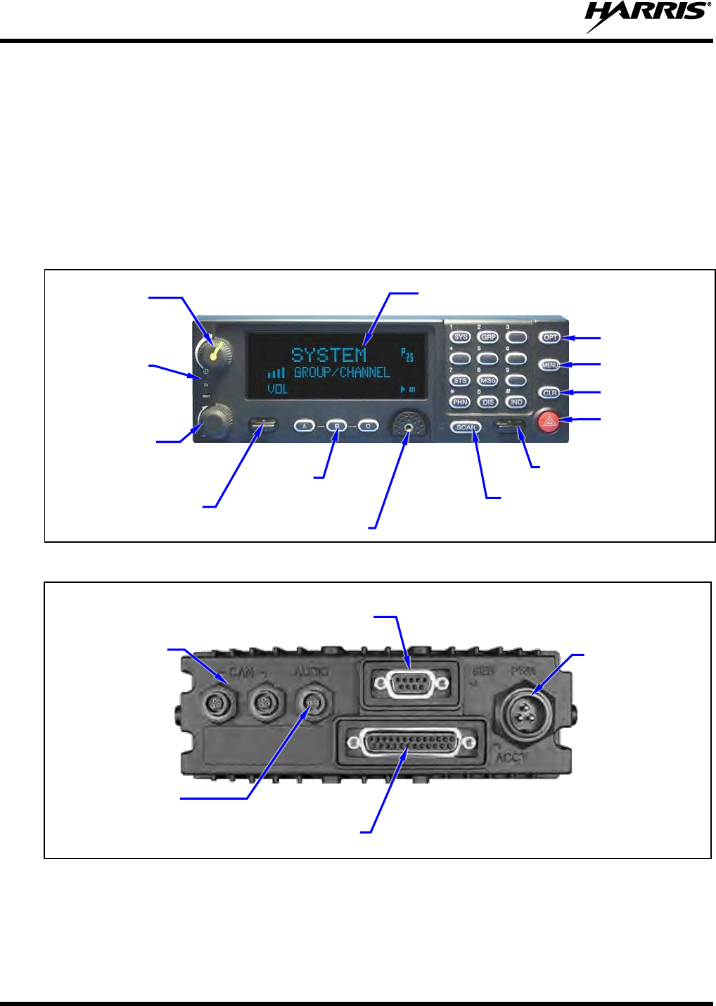
14221-1200-4010, Rev. B
58
10.3 GENERAL INFORMATION ON THE CH-721 CONTROL HEAD
The CH-721 System model control head, shown in Figure 10-4, features a large easy-to-read 3-line
graphical vacuum fluorescent display, an on/off/volume control, menu controls and buttons, trunking
mode buttons, an emergency/home button, a scan on/off button, and three (3) preset buttons. The head
features a 12-key keypad to allow advanced operations without the need of a DTMF-capable microphone.
Other front panel components include a microphone connector and two LED-type indicators. One LED
indicator is the busy indicator that lights when the radio is receiving a call and one is the transmitter-
enabled indicator that lights when the radio is transmitting. All buttons are backlit for viewing in low-
light conditions. Figure 10-5 shows the head’s rear panel.
Figure 10-4: CH-721 System Model Control Head Front Panel
Figure 10-5: CH-721 Control Head Rear Panel
CAN Port
Connectors
(2 places)
Speaker Audio
Connector
Serial Port Connector
(Female DB-9)
DC Power
Connector
Accessory Connector
(Female DB-25)
Note: Serial and Accessory connectors are
shown without waterproof covers.
3-Line Graphical Vacuum
Fluorescent Display
Microphone Connector
On/Off/
Volume
Control
System/-
Group/-
Channel
Selection
Control
/ Ramp Control
Preset/
Softkey
Buttons
Emergency/
Home Button
+/- Ramp Control
Transmit
and Busy
Indicators
Scan On/Off Button
Clear Button
Menu Button
Option Button
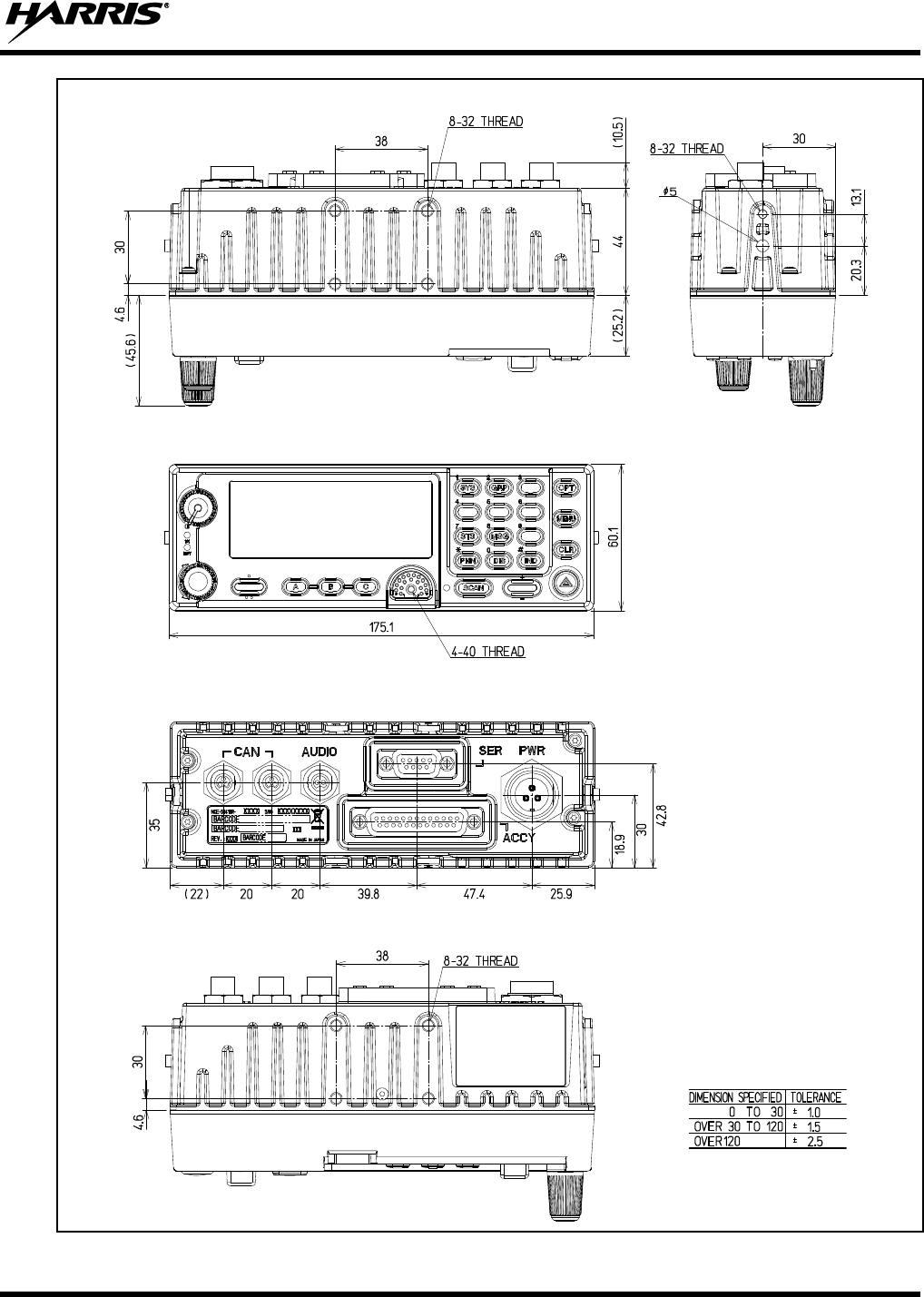
14221-1200-4010, Rev. B
59
Figure 10-6: CH-721 Control Head Dimensions (System Model Shown)
SIDE VIEWTOP VIEW
FRONT VIEW
NOTE: All dimensions
are in millimeters.
Tolerance Table
BOTTOM VIEW
REAR VIEW
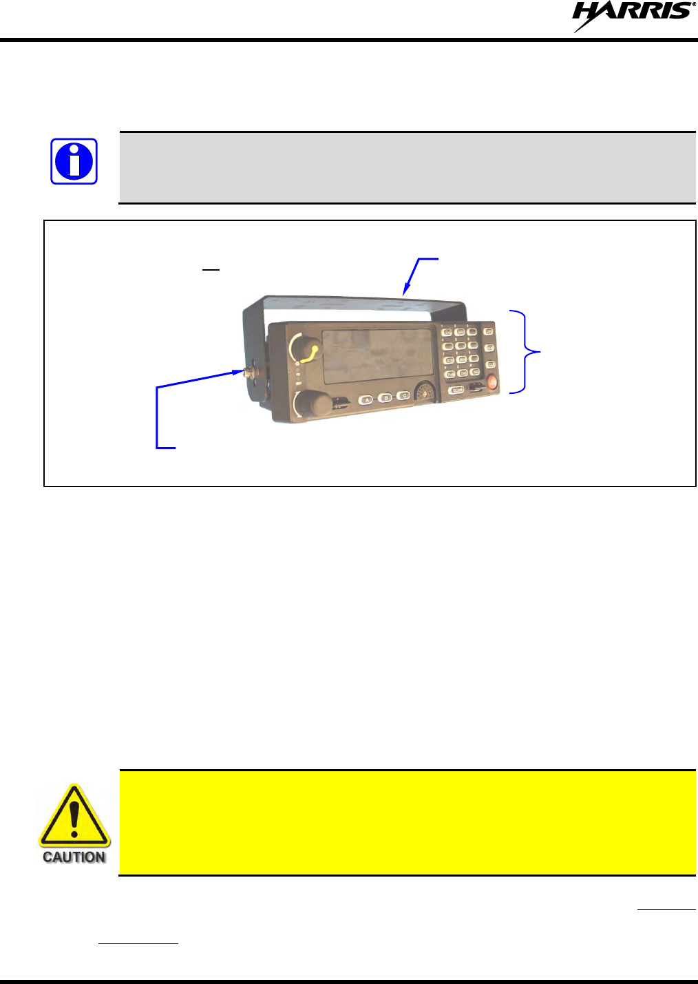
14221-1200-4010, Rev. B
60
10.4 CONTROL HEAD MECHANICAL INSTALLATION
Refer to Section 10.5 for CAN link installation information.
Prior to installing the control head, verify it has the proper software version installed and
verify it has been properly configured for customer use. Consult the radio system
administration personnel as necessary.
Figure 10-7: Standard U-Shaped Control Head Mounting Bracket for CH-721 Control Head
Use the following procedure to install the standard U-shaped mounting bracket.
1. Obtain the mounting bracket from the respective installation kit.
For the CH-100 control head, this is part no. 12099-1500-01 shown in Table 5-3.
For the CH-721 control head, this is part no. KT-008608 shown in Table 5-4.
2. Using the mounting bracket as a template, mark and drill mounting holes into the mounting surface as
required.
The round and elliptical holes in the bracket’s vehicle mounting surface are symmetrical, so
forwards/backwards positioning is not important during this step. However, positioning is important
in the next step.
Before drilling holes and/or installing mounting screws, verify these operations will not
damage or interfere with any existing vehicle component (fuel tank, fuel line, transmission
housing, existing vehicle wiring, etc.). Always check to see how far the mounting screws
will extend below the mounting surface prior to installation. Always deburr drilled holes
before installing screws.
3. Postion the bracket at the mounting surface so the two round holes in its two side “ears” are nearest to
the normal location of the operator (typically towards the rear of the vehicle) and the two slotted holes
are furthest from the normal location of the operator (typically towards the front of the vehicle).
NOTE
Mounting Bracket (Shown
positioned above control head)
Bracket shown
attached to a CH-721
System model
control head
Socket-Head Cap (Allen) Screw and Flat Washer;
2 places each side (Included with kit)
NOTE: If the Bracket Kit
includes lock washers, do not
use them. Only a flat washer
should be used with each cap
screw. The cap screws have
nylon thread-locking patches
on their threads.
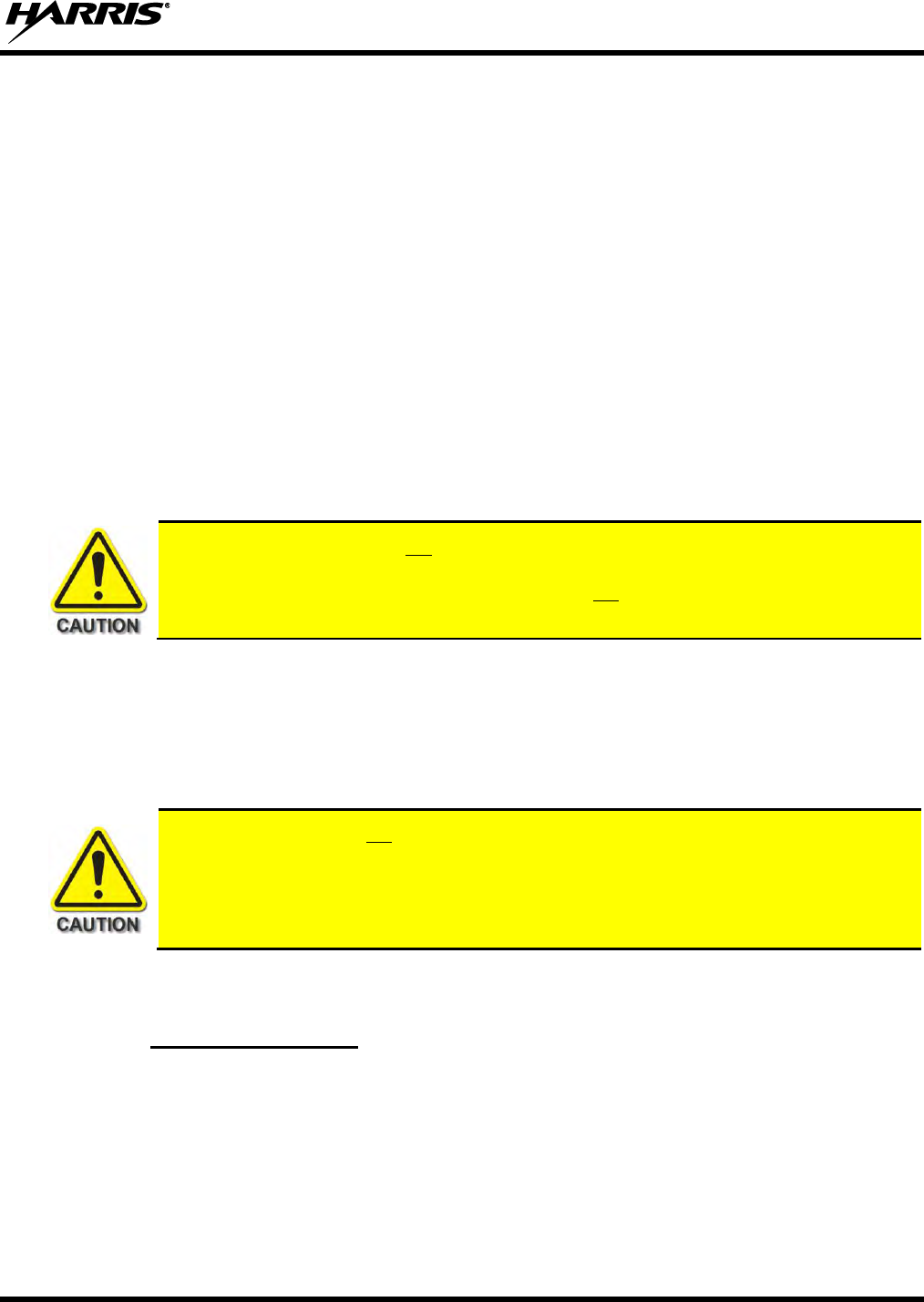
14221-1200-4010, Rev. B
61
4. Install and tighten the mounting screws (not included).
Screws for mounting the bracket to the mounting vehicle’s surface are not included, as all
installations differ. Self-threading screws are recommended. Use of self-drilling screws may cause
damage to some mounting surfaces, such as a plastic dash panel.
5. Verify the bracket is held firmly to the mounting surface.
Firm mounting prevents unreasonable vibration, which could damage the control head and/or cause
its cable connections to loosen.
6. Slide the control head into the bracket, placing the two pegs protruding from its left and right sides
into the respective round holes in the bracket’s two side “ears.”
7. In each “ear” of the mounting bracket, start a socket-head cap (Allen) head screw with a flat washer
by inserting the screw through the slotted hole in the bracket and then into the threaded hole in the
side of the control head.
This hardware is included with the Mounting Bracket Kit. Turn each screw clockwise to tighten it.
Recommended torque is 8.7 inch-pounds (10 kg/cm).
As noted in Figure 10-7, do not use lock washers with the U-shaped bracket, even if they
are included in the kit. Each cap screw has a nylon thread-locking patch imbedded in its
threads, so no lock washer is required. Also, do not use any additional thread locking
compound with the cap screws.
8. Position the control head for the operator’s best viewing angle.
It may be necessary to turn it on the pegs to a good viewing position
9. Tighten both screws using a ⅛-inch hex key (Allen) wrench until the control head is held firmly in
place. Do not over-tighten.
Each cap screw should not be installed/re-used more than eight (8) times, because thread
locking strength may suffer after this number of re-installations. Replace the cap screws
with new cap screws if their locking strength is in question and/or after exceeding eight (8)
installations. Hardware Kit 14002-0172-01 is available for this purpose. It includes two
#8-32 self-locking socket-head cap screws and two #8 flat washers.
10.5 CONTROL HEAD-TO-RADIO CAN CABLE CONNECTIONS
10.5.1 General Information
A remote-mount radio installation requires a CAN cable between every two “CAN devices” and CAN
terminators on each end of the CAN link. The mobile radio (XG-100M) is considered a CAN device, and
each control head in the installation is also considered a CAN device. Figure 10-8 illustrates CAN cable
and CAN terminator connections for a single control head installation. Because CAN devices do not have
internal terminators, the CAN link must be terminated at both ends via external CAN terminators, as
depicted in the following figures.
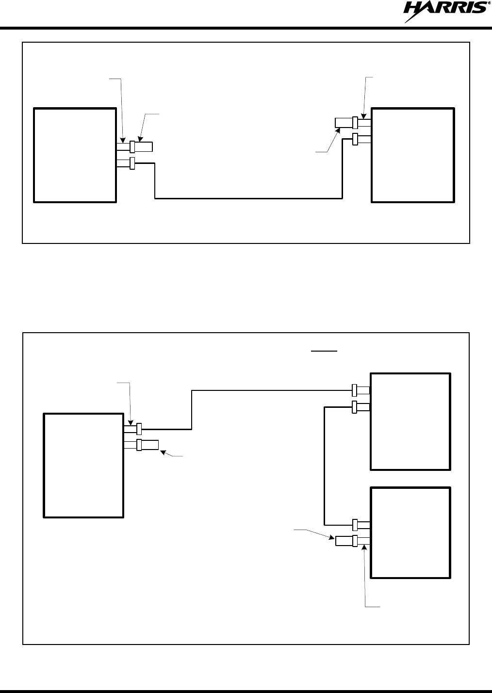
14221-1200-4010, Rev. B
62
CAN Terminator CD-014027-001
(for control head)
MRU
Mobile
Radio
(XG-100M)
CAN Cable CA-009562-030nn
CAN Terminator CD-014027-001
(for MRU)
CAN
3-Pin CAN Port
Connectors on
Rear of Radio
(2 places)
CAN
CAN
CH-100
or
CH-721
Control
Head
CAN
3-Pin CAN Port
Connectors on Rear
of Control Head
(2 places)
Figure 10-8: CAN Link Connections for a Single Control Head Installation
An MRU and the control head have two CAN ports that enable supporting “daisy-chaining” multiple
control heads or other CAN devices. Figure 6-2 on page 31 shows the radio’s two CAN port connectors,
which are located near the center of the radio’s rear panel. Figure 10-2 (CH-100) on page 56 and Figure
10-5 (Ch-721) on page 58 show the two CAN port connectors on the control head’s rear panel.
CAN Cable CA-009562-nnn
(where nnn specifies cable length in feet)
NOTE #2: The XG-100M mobile radio may be located in the middle of the CAN link.
For a 2-head installation, two CAN cables would connect directly to the two CAN port
connectors on the rear of the radio, and each control head would require a CAN
terminator. When the radio is in the middle of the CAN link, no CAN terminator is
required at the radio. The radio can support up to six (6) control heads.
CH-100
or
CH-721
Control
Head #1
(e.g., at main
operator location)
CAN Cable CA-009562-nnn
(where nnn specifies cable length in feet)
CAN Terminator CD-014027-001
(for control head end)
(See NOTE #3)
CAN
3-Pin CAN Port
Connectors on
Rear of Radio
(2 places)
CAN
CAN
MRU
Mobile
Radio
(XG-100M)
CAN
3-Pin CAN Port
Connectors on Rear
of Control Head
(2 places)
CAN
CAN CH-100
or
CH-721
Control
Head #2
(e.g., near rear of
vehicle)
CAN Terminator CD-014027-001
(for radio end)
NOTE #1: CH-100 and CH-721 control heads cannot be
used together (i.e., mixed) within a radio installation.
NOTE #3: Right-Angle CAN Terminator MACDOS0010 also is available. This CAN
terminator can be used if the physical clearance at the back of the head is insufficient
for CAN Terminator CD-014027-001.
Figure 10-9: CAN Link Connections for a Dual Control Head Installation
14221-1200-4010, Rev. B
63
10.5.2 Make CAN Link Terminations and Cable Connection
Follow this procedure:
1. Get the two (2) CAN terminators, part number CD-014027-001, from the installation kit.
2. Mate one terminator to either one of the two smaller 3-pin CAN port connectors on the rear panel of
the control head.
When mating any CAN connection (terminators and cables) to a rear panel connector,
visually align the ¾-moon-shaped keys of the connectors, and then gently push and turn the
outer locking ring of the plug (male) connector clockwise until it stops. A mild click will be
sensed to confirm proper mating. Without visual alignment as a guide, it is possible with
excessive force to mate the CAN connectors improperly. Damage to the connector(s) may
result. Therefore, visual alignment is recommended when mating CAN connectors.
3. Continue CAN cable installation by routing it to the area near the rear of the control head.
The cable should have been partially installed using the procedure in Section 9.2.1.2, when the CAN
cable was partially installed along with the red wire of the radio’s DC Power Cable.
If the mobile radio installation must be interfaced to a Mobile Data Terminal and/or other
equipment, simultaneous routing of the related interface cables along with the CAN cable
will be time-saving. For GPS equipment cable part numbers and cable installation
procedures, refer to Section 13.5.
4. Mate one end of the CAN cable to the other CAN port connector on the rear panel of the control head.
5. If not already mated, mate the other end of the CAN cable to one of the two CAN port connectors on
the rear panel of the radio.
6. Mate the second CAN terminator to the other CAN port connector on the rear panel of the radio.
7. Any necessary option/accessory cables from the back of the radio can also be routed with this wire
and cable within the vehicle’s interior (i.e., up to but not through the vehicle’s firewall).
8. Loop, tie, and stow the cable(s) as necessary, leaving a service loop at the back of the radio and at the
back of the control head. Protect the entire length of the cable(s) and wire(s) from possible chafing.
10.6 CONTROL HEAD POWER CABLE INSTALLATION
Plan the route of the control head’s DC Power Cable carefully. Do not route the cable where it will be
damaged by heat sources or by casual contact, and protect it from wire chafe per standard installation
methods. The following procedures are recommended:
NOTE
NOTE
14221-1200-4010, Rev. B
64
10.6.1 Install DC Power Cable and Make Power and Ground Connections
1. Get the control head’s DC Power Cable from the its installation kit. This is part no. CA-012616-001
in Table 5-3 (CH-100) or Table 5-4 (CH-721).
2. Connect this cable to the large 3-pin connector at the rear of the head. Visually align the key and
gently push and turn the outer locking ring clockwise until it stops. A click will be sensed to confirm
proper mating.
3. At the back of the control head, locate a nearby section of vehicle chassis ground and strip this area of
any paint or dirt to expose a bare metal surface.
4. Cut the black wire of the control head’s DC Power Cable to the required length, plus a service loop of
at least six (6) inches, then strip it and crimp a ⅜-inch ring terminal to it. Two ring terminals of this
type are included with the cable.
5. Drill a hole, as necessary, and attach this ring terminal to chassis ground. Use stainless-steel self-
locking hardware (i.e., machine screws with washers and locking nuts) or other appropriate hardware
to ensure reliable terminal-to-metal contact. Tighten securely.
6. At the back of the control head, tie and stow the cable as necessary.
7. For the positive 12-volt DC main power source connection, route the cable’s red wire to the location
of an unswitched 12-volt DC power source, typically near the vehicle’s battery.
Remove interior panels, door kick panels, etc. as needed. Protect the wire from possible chafing as
necessary. This is the control head’s main DC power source.
8. Obtain one of the yellow waterproof (HFB-type) fuse holders included with the control head’s DC
Power Cable.
9. Cut excess length from the red wire and splice the fuse holder into it, near the location of the
unswitched 12-volt DC power source connection point.
If necessary, a small amount of cable soap may be used to help slip the wire through the small end of
the fuse holder’s insulator.
10. Using an appropriate electrical terminal, connect the red wire to the unswitched DC power source.
A ⅜-inch ring terminal is included with the cable for this purpose, but another terminal type (not
supplied) may be used if required.
11. Obtain the 5-amp AGC-type fuse included with the cable, and install it into the fuse holder.
The fuse for the control head’s red wire is rated at 5 amperes. The 3-amp fuse included with
the cable must not be used for fusing the control head’s main DC power. It fuses the head’s
white wire.
Do not share the control head’s fuse with any other device. Doing so can cause excess
current to flow through the fuse, causing it to blow unnecessarily.
NOTE
14221-1200-4010, Rev. B
65
10.6.2 Connect DC Power Cable’s White Wire
A review of the information presented in Section 9.1 (page 50) may be beneficial at this time. As required
per the chosen power-up configuration, connect the white wire by following one of the three procedures
presented in the respective sub-section that follows.
10.6.2.1 Control Head and Radio Turn on with Vehicle’s Ignition Switch/Key
With this wiring configuration, the control head and radio automatically turn on and off with the vehicle’s
ignition switch/key. The white wire of the control head’s DC Power Cable is sometimes referred to as the
“white ignition switch wire” or the “ignition sense input wire.” In this configuration, the white wire
connects to a switched power source, typically identified as “Accessory” power, that switches on and off
with the vehicle’s ignition switch/key. When using this configuration, the control head’s on/off/volume
control must be left in the on position for automatic power-up/down to function properly.
The white ignition sense wire must be connected to a fused power source that switches from
approximately zero volts to approximately +13.6 volts when the vehicle’s ignition
switch/key is turned from the OFF position to the ACCESSORY and RUN positions. Use of
a switched power source that is subject to voltage changes as a result of other actions, such
as opening a vehicle door, may result in undesirable radio power cycles.
1. Locate the vehicle’s switched ignition or “Accessory” power connection point that will be used for
the switched ignition 12-volt DC power source.
This point is typically located at or near the vehicle’s fuse panel. It may be necessary to consult the
vehicle manufacturer’s wiring diagram.
2. Route the white wire of the control head’s DC Power Cable from the back of the head to the area near
this connection point. Protect the wire from possible chafing as necessary.
3. Obtain one of the yellow waterproof (HFB-type) fuse holders included with the control head’s DC
Power Cable.
4. Cut excess length from the white wire and splice the fuse holder into it, near the location of the
connection point.
5. Using an appropriate electrical terminal, connect the white wire to the switched power connection
point. An open-barrel spade terminal is included with the cable for this purpose, but another type of
terminal (not supplied) may be used as required.
6. Obtain the 3-amp AGC-type fuse included with the cable, and install it into the fuse holder.
7. Tie and stow all wiring as necessary so it remains out of the way of casual contact and wire chafe is
avoided.
NOTE

14221-1200-4010, Rev. B
66
10.6.2.2 Control Head and Radio Turn On with a Manual Switch
With this wiring configuration, the control head and radio are manually turned on and off via an on/off
switch mounted separately from the control head and radio, not through the vehicle’s ignition switch/key.
This configuration is used when, for example, the radio must remain on even when the ignition key must
be removed from the vehicle and a separate on/off switch is acceptable and/or required. In this
configuration, the white wire connects to a fused switched power source such as that provided by a toggle
switch mounted on the vehicle’s dash panel. When using this configuration, the on/off/volume control
must be left in the on position. Otherwise, the radio will remain off when the switch is on.
1. Route the white wire of the control head’s DC Power Cable from the back of the head to an area near
the location of the panel-mounted on/off switch. Protect the wire from possible chafing as necessary.
2. Cut a short section (6 to 8 inches) off the end of the white wire and strip the ends.
3. Obtain one of the yellow waterproof (HFB-type) fuse holders included with the control head’s DC
Power Cable, and crimp one half of it to one end of the short section of wire.
4. Using an appropriate electrical terminal, connect this short white wire to unswitched 12-volt DC
power source at or near the vehicle’s fuse box.
5. Cut another section of white wire from the cable. This wire must be long enough to reach from this
fuse holder to the location of the panel-mounted on/off switch.
6. Strip one end of this wire and crimp the other half of the waterproof fuse holder to this wire end.
7. Strip the other end of this wire and, using an appropriate electrical terminal, connect it to the common
terminal of the switch.
8. Connect the white wire of the power cable to the load (switched) side of the switch.
9. If not already, mount the switch to the vehicle’s dash panel, or other customer-selected location.
10. Obtain the 3-amp AGC-type fuse included with the cable, and install it into the fuse holder.
11. Tie and stow these wires as necessary so they remain out of the way of casual contact and wire chafe
is avoided.
12. Label this power switch accordingly. For example: “RADIO ON/OFF.”
10.6.2.3 Control Head and Radio Are “Hot Wired”
In the “hot-wired” configuration, the control head and radio are turned on and off only by the control
head’s on/off/volume control located on the front panel of the control head. In this configuration, the
control head’s white wire must be connected to unswitched and fused 12-volt vehicle power. Follow the
procedure presented in Section 10.6.2.1, except connect the white wire to unswitched battery power
instead of switched (“Accessory”) power. Be sure to fuse this connection with the provided in-line fuse
holder and 3-amp AGC fuse.

14221-1200-4010, Rev. B
67
11. SPEAKER INSTALLATION
Select a location for the speaker that will allow for proper listening range with a moderate volume setting.
Total speaker cable length (of both cables) is approximately five (5) feet. Therefore, to include service
loops in the cables, the speaker must be mounted within approximately 4.5 feet of the control head.
1. Install the speaker LS102824V10 in Table 5-3 (CH-100) or Table 5-4 (CH-721) using the hardware
and mounting bracket supplied with it.
Also refer to the instructions included in the speaker for additional mechanical installation
information.
2. Route the speaker’s cable to the rear of the control head.
3. Mate the Speaker Cable MAMROS0034-NN006 [Table 5-3 (CH-100) or Table 5-4 (CH-721)] to the
2-pin “AUDIO” connector at the rear of the control head by visually aligning the ¾-moon-shaped
keys of the connectors. Push and turn the outer locking ring of the cable connector clockwise until it
stops. A mild click will be sensed to confirm proper mating.
4. Connect the speaker’s 2-pin plastic connector to the respective mating connector on the Speaker’s
cable.
5. Route the cables out of the way of casual contact and tie and stow as necessary.
12. MICROPHONE ATTACHMENT
There are several versions of microphones available for use with the CH-100 and CH-721 control heads.
Each microphone has a 17-pin flush-mount type connector that mates with the microphone (“mic”)
connector on the front panel of the control head. The mic’s connector includes a captive thumbscrew that
secures it to the mic connector on the front panel of the control head. A microphone clip is included with
each microphone. The radio can be configured to provide a monitor function when the microphone is
cradled in the clip. Connect the mic to the control head and install the clip as follows:
1. Grasp the mic’s connector with a thumb and index finger on the sides of the connector just adjacent to
the thumbscrew.
2. Position connector just in front of the control head’s mic connector so its male pins can engage
straight into the female (socket) pins of the control head’s mic connector. The thumbscrew must be
oriented directly below the hanging mic cable.
3. Mate the two connectors by pressing them fully together. Do not apply any force to the thumbscrew
when mating the connectors.
4. Tighten the thumbscrew finger-tight. Do not use a screwdriver to tighten it.
5. Using the microphone clip as a template, drill mounting holes in the surface of the selected location.
6. Select a mounting surface location that has clearance for the mic when it is clipped to the clip, and
then attach the microphone clip to the surface. Use self-locking hardware (i.e., machine screws with
washers and locking nuts), self-drilling screws, or other appropriate hardware as necessary. Tighten
securely. Microphones used with the CH-100 and CH-721 control heads have integrated
hookswitches. Therefore, the microphone clip does not need to be grounded.
7. Clip the microphone to the clip.
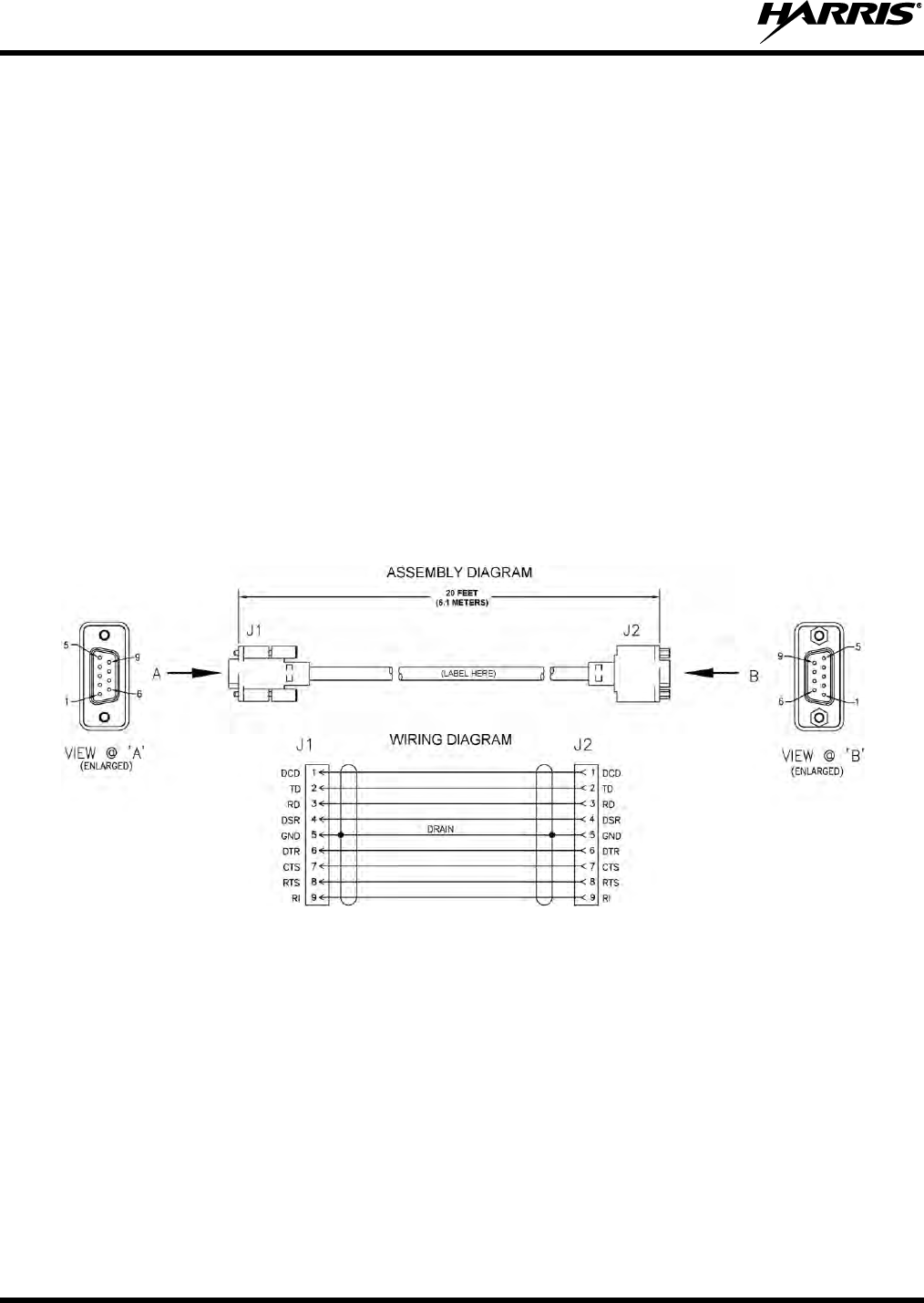
14221-1200-4010, Rev. B
68
13. OPTIONAL CABLES
13.1 SERIAL PROGRAMMING CABLE CA-013671-020
Serial Programming Cable CA-013671-020 (20 feet long) can be used to program and configure the MRU
using a Personal Computer (PC). This cable can also be used to extend the length of GPS
NMEA-formatted serial data connections. The cable’s assembly and wiring diagrams are shown in Figure
13-1 below.
To program and configure the MRU, the cable’s male DB-9 connector (J1) is mated to the female DB-9
serial port connector on the rear of the MRU. Alternately, if the cable is being used to carry GPS
NMEA-formatted serial data from the MRU, its male DB-9 connector mates to connector P5 of Interface
Cable 14002-0174-03.
The cable’s female DB-9 connector (J2) mates to a PC’s male DB-9 serial port connector. If the PC is not
equipped with a DB-9 serial port connector, use a suitable adapter, such as USB-to-RS-232 Adapter
Cable CN24741-0001. The CN24741-0001 can be ordered through the Customer Care center; refer to
Section 4.3 on page 21 for contact information.
(Made From PS-CA-013671 Rev. -)
Figure 13-1: Serial Data Cable CA-013671-020
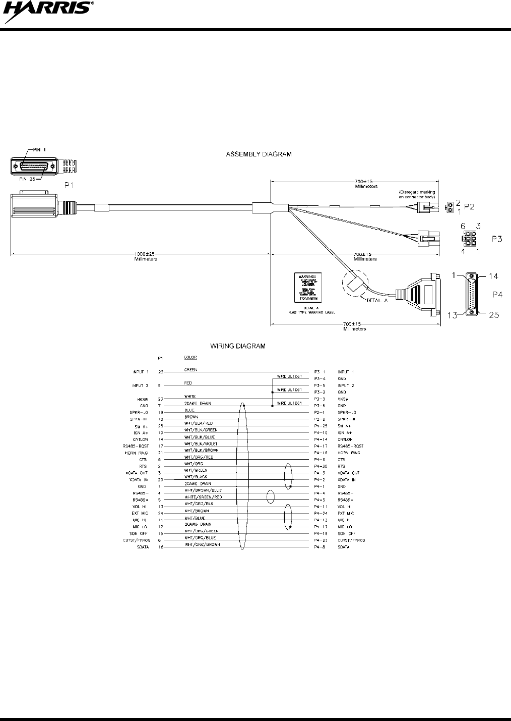
14221-1200-4010, Rev. B
69
13.2 CH-100/CH-721 OPTION CABLE CA-011854-001
CH-100/CH-721 Option Cable CA-011854-001 can be used to connect optional equipment to the 25-pin
D-subminiature (DB-25) connector on the rear of the CH-100 or CH-721 control head. This cable
expands the connections available at the 25-pin connector to three (3) separate connectors. The cable’s
assembly and wiring diagrams are shown in Figure 13-2 below.
(Made From PS-CA-011854 Rev. D)
Figure 13-2: CH-100/CH-721 Option Cable CA-011854-001
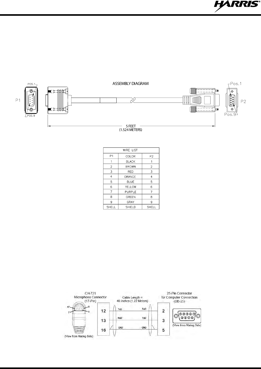
14221-1200-4010, Rev. B
70
13.3 CH-721 SERIAL PROGRAMMING CABLE CA-104861
Serial Programming Cable CA-104861 (5 feet) can be used to program and configure the CH-721 control
head via a Personal Computer. This cable has a female DB-9 connector on one end for connection to the
PC’s serial port connector and a male DB-9 connector on the other end for connection to the serial port
connector on the rear of the head. The cable’s assembly diagram and wiring list are shown in Figure 13-3
below.
(Made From PS-CA-104861 Rev. B)
Figure 13-3: Programming Cable CA-104861
13.4 CH-721 MIC CONNECTOR PROGRAMMING CABLE CA-103541-001
CH-721 Mic Connector Programming Cable CA-103541-001 (4 feet long) can be used to program and
configure the CH-721 control head via its front-panel microphone connector. It has a female DB-9
connector on one end for connection to a PC’s serial port connector and a 17-pin Conxall-style connector
on the other end for connection to the head’s mic connector. Refer to the respective Software Release
Notes for programming and configuration information.
(Made From PS-CA-103541 Rev. A)
Figure 13-4: CH-721 Serial Programming Cable CA-103541-001
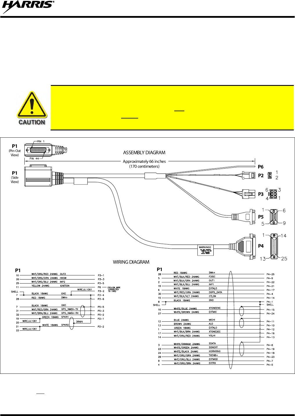
14221-1200-4010, Rev. B
71
13.5 OPTION CABLE 14002-0174-01
Option Cable 14002-0174-01 connects to the 44-pin I/O connector on the rear of the radio. It breaks out
into several smaller standardized connectors, allowing straightforward access to external I/O interfaces
provided by the radio. The cable also shortens radio removal and re-installation time when required. The
cable is shown in Figure 13-5 below. The cable’s 44-pin D-subminiature connector P1 mates with the 44-
pin I/O connector on the rear of the radio.
Observe caution before connecting any external device to the radio via its 44-pin I/O
connector. If an external device has its own DC power source/cable (i.e., if it is powered
separately from the radio), both the radio and the external device must be properly
grounded to the vehicle before connecting the two units together and before making a
positive (+) DC power connection to either unit. Otherwise, equipment damage may occur.
(Made From D14002-0174 Sh. 1 and 2, Rev. C)
Figure 13-5: Option Cable 14002-0174-01
P2 is not used in a remote-mount radio installation, since the audio amplifier in the control head drives the
external speaker (speaker connection is made at the rear of the control head).
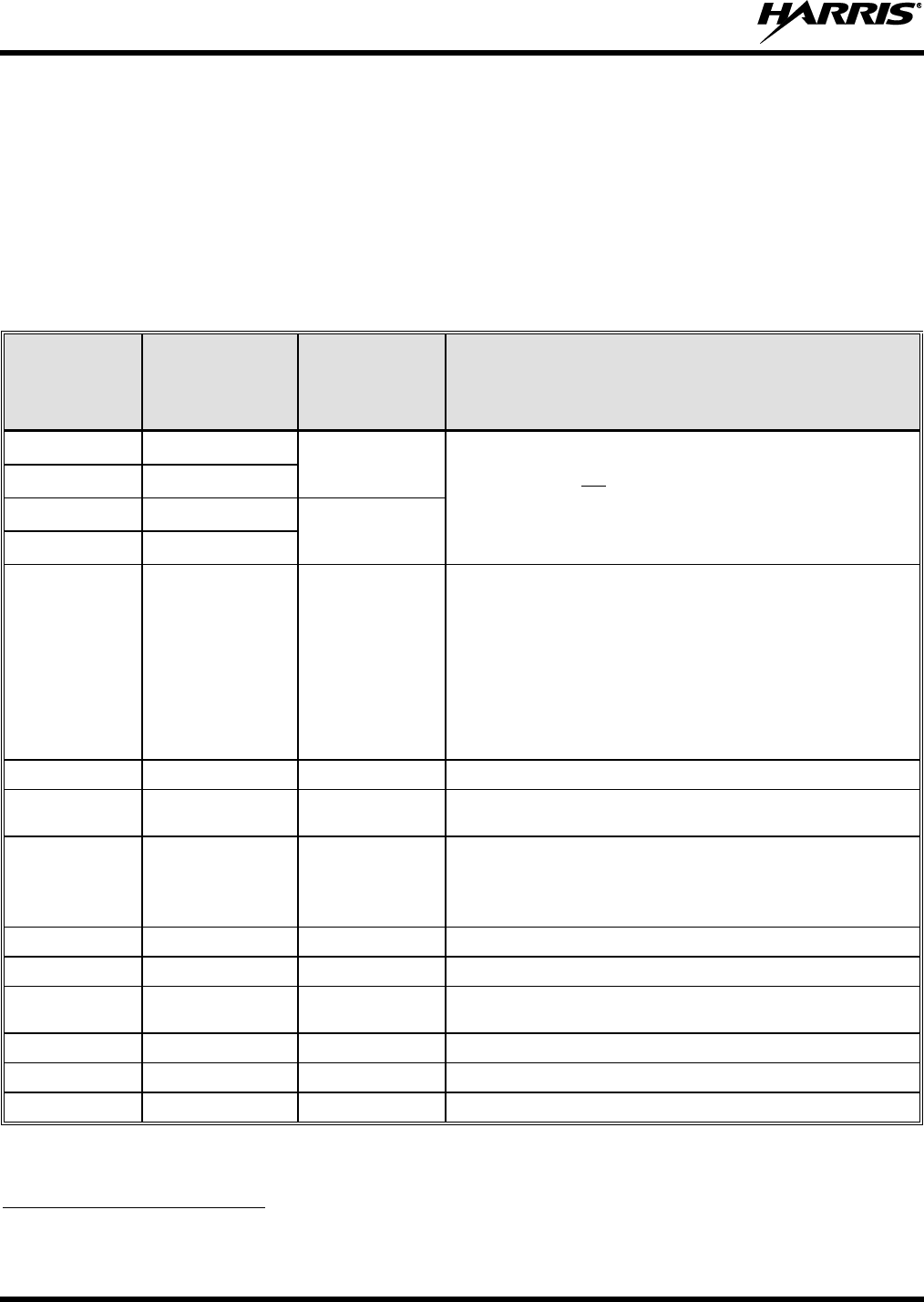
14221-1200-4010, Rev. B
72
P3, the cable’s 6-pin connector, is a connector for basic accessories (e.g., hookswitch, external relay with
back-EMF diode, etc.).
P4, the cable’s D-subminiature 25-pin connector, provides audio and data connections for optional
equipment such as an external siren and light system (e.g., Federal Signal SS2000 SmartSiren®), external
relay with back-EMF diode, etc.
P5, the cable’s D-subminiature 9-pin connector, provides NMEA-formatted GPS serial data connections
for the external computer processing the NMEA-formatted GPS data received by the radio’s internal GPS
receiver. See Section 13.5 on page 71 for additional information.
Table 13-1: Option Cable 14002-0174-01 Interconnections
44-PIN I/O
CABLE
CONNECTOR
P1 PIN
SIGNAL NAME
TO/FROM
DESCRIPTION
19
SPKR1
P2 pin 1
This output is not functional in a remote-mount radio
installation; since the speaker output from the control
head drives the external speaker.
20
SPKR1
21
SPKR2
P2 pin 2
22
SPKR2
10
OUT2
P3 pin 1
Digital Output 2 (open-collector, 100 mA / 17 V maxi-
mum). An external pull-up resistor is needed if required
by the external device’s input during the high/off state.
Use P3 pin 2 or 4 for ground.
Configure via the “External Output Control Line 2” in Radio
Personality Manager’s (RPM’s) External I/O dialog box. For
example, an external logging recorder’s record
enable/disable input can be controlled by setting “External
Output Control Line 2” to “Extern. Tx Indicator.”
7
GND
P3 pins 2 & 4
Chassis Ground (fused inside radio).
26
HKSW
P3 pin 3
Digital Input for Hookswitch (default) or for radio PTT.
Active = Ground. Inactive = Open.
25
INP2
P3 pin 5
Digital Input 2. Active = Ground. Inactive = Open. Use P3
pin 2 or 4 for ground.
Configure via the “Auxiliary Input 2” in Radio Personality
Manager’s (RPM’s) External I/O dialog Box.
28
SWA+
P3 pin 6
Switched A+ (DC Power) Output.
8
GND
P4 pin 1
Chassis ground (fused inside radio).
30
DGPS_DATA
P4 pin 4
GPS Receiver Module DGPS Correction Data Serial Data
Input (NMEA formatted).
4
EXTRX
P4 pin 5
External Rx Audio Input (from external/2nd receiver; summed).
9
RESERVED
P4 pin 7
Not used.
3
SDATA
P4 pin 8
For a remote-mount radio installation, see footnote 2.
2 In a remote-mount XG-100M radio installation, this pin on the radio’s DB-44 connector is inactive/disabled. For the
CH-100 or CH-721 control head, use the respective pin on the Control Head Option Cable’s female DB-25 pin connector;
see Section 13.2 for additional information.

14221-1200-4010, Rev. B
73
Table 13-1: Option Cable 14002-0174-01 Interconnections
44-PIN I/O
CABLE
CONNECTOR
P1 PIN
SIGNAL NAME
TO/FROM
DESCRIPTION
5
FDISC
P4 pin 9
Buffered Filtered Discriminator Audio Output (not
normally used). A fixed-level audio output with DC bias.
Approximately 200 mVrms into a 600-ohm load at rated
deviation. Does not contain signaling (e.g., CTCSS).
Mutes when speaker mutes. Use a 33 µF / 50 V (or
greater) coupling capacitor to connect to a 600-ohm load.
Use P4 pin 12 for ground.
13
ALO
P4 pin 10
In a remote-mount radio installation, these two pins of the
radio’s DB-44 connector are not functional.
12
MICHI
P4 pin 11
1
EXTALO
P4 pin 12
VOLHI (a single-ended AC-coupled audio signal) and
EXTALO (signal ground) provide an unmuted volume-
level-controlled single-ended receive audio signal to
external devices. P1 pin 1 (EXTALO) is over-current
protected inside the radio by a 1-amp fuse.
14
VOLHI
P4 pin 13
15
CTLON
P4 pin 14
Control-On Digital Input. Logically OR’d inside radio with
a CAN receiver activity logic signal, so either input can
turn on the radio. Not normally used.
16
XTONEENC
P4 pin 15
External Tone Encode Audio Input (default) or Auxiliary
Mic Audio Input.
17
XTONEDEC
P4 pin 16
External Tone Decode Audio Output.
6
EXTALO
P4 pin 17
Reference/Ground for external audio. Over-current-
protected inside the radio by a 1-amp fuse.
24
HORNRING
P4 pin 18
For a remote-mount radio installation, see footnote 2.
23
SONOFF
P4 pin 19
For a remote-mount radio installation, see footnote 2.
18
INP1
P4 pin 21
Digital Input 1. Active = Ground. Inactive = Open. Use P4
pin 1 for ground.
Configure via the “Auxiliary Input 1” in Radio Personality
Manager’s (RPM’s) External I/O dialog Box.
2
OUT1
P4 pin 22
Digital Output 1 (open-collector, 100 mA / 17 V maxi-
mum). An external pull-up resistor is needed if required
by the external device’s input during the high/off state.
Use P4 pin 1 for ground.
Configure via the “External Output Control Line 1” in
Radio Personality Manager’s (RPM’s) External I/O dialog
Box.
29
TXENB+
P4 pin 23
Transmit Enable B+ Output (open-collector). Active/Radio
Transmitting = Ground. Inactive/Not Transmitting = Open
(not normally used).
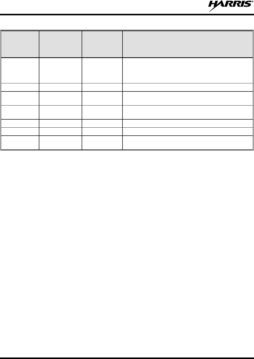
14221-1200-4010, Rev. B
74
Table 13-1: Option Cable 14002-0174-01 Interconnections
44-PIN I/O
CABLE
CONNECTOR
P1 PIN
SIGNAL NAME
TO/FROM
DESCRIPTION
27
EXTMIC
P4 pin 24
External/Auxiliary Mic Audio Input. Fixed-level audio input
(i.e., input gain is not adjustable). Approximately
120 mVrms gives full-rated deviation. Use P4 pin 17 for
ground.
28
SWA+
P4 pin 25
Switched A+ DC Power Output (not normally used).
32
GPS_NMEA_RX
P5 pin 2
NMEA-Formatted GPS Receiver Position Data Serial
Data Output.
31
GPS_NMEA_TX
P5 pin 3
NMEA-Formatted GPS Receiver Module Initialization
Data Serial Data Input.
7
GND
P5 pin 5
Ground for GPS Serial Data Signals (fused inside radio).
11
IGNITION
Yellow Wire
Unused/Spare ignition sense input.
33 — 44
—
(no connections)
These twelve pins of P1 are not used/not connected
when Option Cable 14002-0174-01 is connected.
14221-1200-4010, Rev. B
75
14. GPS NMEA-FORMATTED SERIAL DATA CONNECTION
To obtain GPS NMEA-formatted serial data from the MRU, use the following procedure to complete the
serial data connections:
1. Connect the DB-9 female connector labeled “GPS” of Interface Cable to the computer’s serial port
DB-9 male connector—either directly or extended via a serial cable. Serial Programming Cable
CA-013671-020 (20 feet) can be used to extend the length; see Section 13.1 for additional
information.
2. Tighten the screws firmly, and then route the cabling as required.
If the computer is not equipped with a DB-9 serial port connector, a suitable adapter is required, such
as USB-to-RS-232 Adapter Cable, Harris part number CN24741-0001.
3. Follow the manufacturer’s instructions on processing the NMEA-formatted GPS data from the radio.
Industry software to process GPS information through this interface is not supported by
Harris.
15. MOBILE DATA CONNECTION
If the radio installation must support mobile data communications of a computer running Mobile Data
Terminal (MDT) or similar software, use the following procedure to connect the computer to the radio:
1. Obtain the Serial Programming cable CA-013671-020 (or equivalent). This is a 20-foot-long standard
serial data cable. It is shown in Figure 13-1 on page 68.
2. Connect this cable’s male DB-9 connector to the female DB-9 connector on the rear of the MRU
radio (XG-100M). Tighten the two (2) connector jackscrews.
3. Route the cable through the vehicle’s interior wire/cable channeling to the computer.
Remove interior panels, door kick panels, etc., as necessary. Protect the cable from possible chafing
and tie-and-stow it as necessary.
4. Connect the cable’s female DB-9 connector to the computer.
If the computer is not equipped with a DB-9 serial port connector, a suitable adapter is required, such
as USB-to-RS-232 Adapter Cable, Harris part number CN24741-0001.
Mobile data should not be obtained from the CH-721 control head.
Before data communications can occur on a P25 system, the respective data option must be
enabled. Contact the Technical Assistance Center (TAC) for additional information. TAC
contact information is included on page 21.
NOTE
NOTE
NOTE

14221-1200-4010, Rev. B
76
16. INITIAL POWER-UP TEST
1. At the main inline fuse holders located near the vehicle battery (or DC power access point); install the
15-amp fuse into the MRU main power fuse holder.
The proper fuse is included with the MRU’s DC Power Cable (installed per Section 9.2.1.2).
2. Install a 30-amp AGC fuse into the fuse holder for LBPA main power.
The fuse is included with the LBPA’s DC Power Cable (installed per Section 9.2.1.2).
3. Install a 5-amp AGC fuse into the fuse holder for the control head’s main power (red wire), if not
previously installed. The fuse is included with the Control Unit’s DC Power Cable.
4. Install a 3-amp AGC fuse into the control head’s ignition sense line (white wire), if used. The fuse is
included with the with the Control Unit’s DC Power Cable.
5. Tie and stow all fuse holders and wiring to prevent excess vibration/movement.
6. Carefully reconnect the vehicle’s battery ground cable.
7. Temporarily connect the multi-band mobile antenna cable from the vehicle-mounted antenna to the
MRU female TNC RF connector “MB ANT.”
This is a temporary connection until test procedures in Section 17 are complete.
8. Temporarily connect the VHF mobile antenna cable from the vehicle-mounted antenna to the MRU
female BNC RF connector “LB ANT.”
This is a temporary connection until test procedures in Section 17 are complete.
9. If the MRU is equipped with the GPS receiver option, permanently connect the antenna cable from
the GPS antenna (or mobile/GPS combo antenna) to the female SMA connector on the rear panel of
the radio.
The male SMA connector on most GPS antenna cables has a 5/16-inch hex collar, so the use of a
wrench of this same size is normally required for tightening. However, some may have collars with
only knurled surfaces, so a standard wrench or torque wrench cannot be used. In either case, do not
over tighten the connector and do not twist the cable when tightening.
10. If the installation is wired so the vehicle’s ignition key/switch turns the radio on and off, turn the
switch to the Accessory or Run position.
11. Rotate the control head on/off/volume control clockwise out of the detent position to apply power to
the radio.
12. Verify the control head has powered-up by observing its display. If the display is not lit, refer to
Section 9.1 as necessary.
As long as the software configuration parameters have been loaded, successful installation is almost
immediately realized:
After a short boot-up sequence, the control head displays login information and/or a talk group.
If no errors are displayed, the installation is most-likely properly wired.

14221-1200-4010, Rev. B
77
If an error is displayed, recheck all cable connections, verify all fuses are properly installed, and
verify battery power is getting to the radios’ main power fuses. If problems persist, contact the
Technical Assistance Center (see page 21).
Consult the Operator’s Manual for operational information. Refer to Section 3.5 on page 18 as
necessary.
13. Perform the necessary performance tests as described in Section 17.
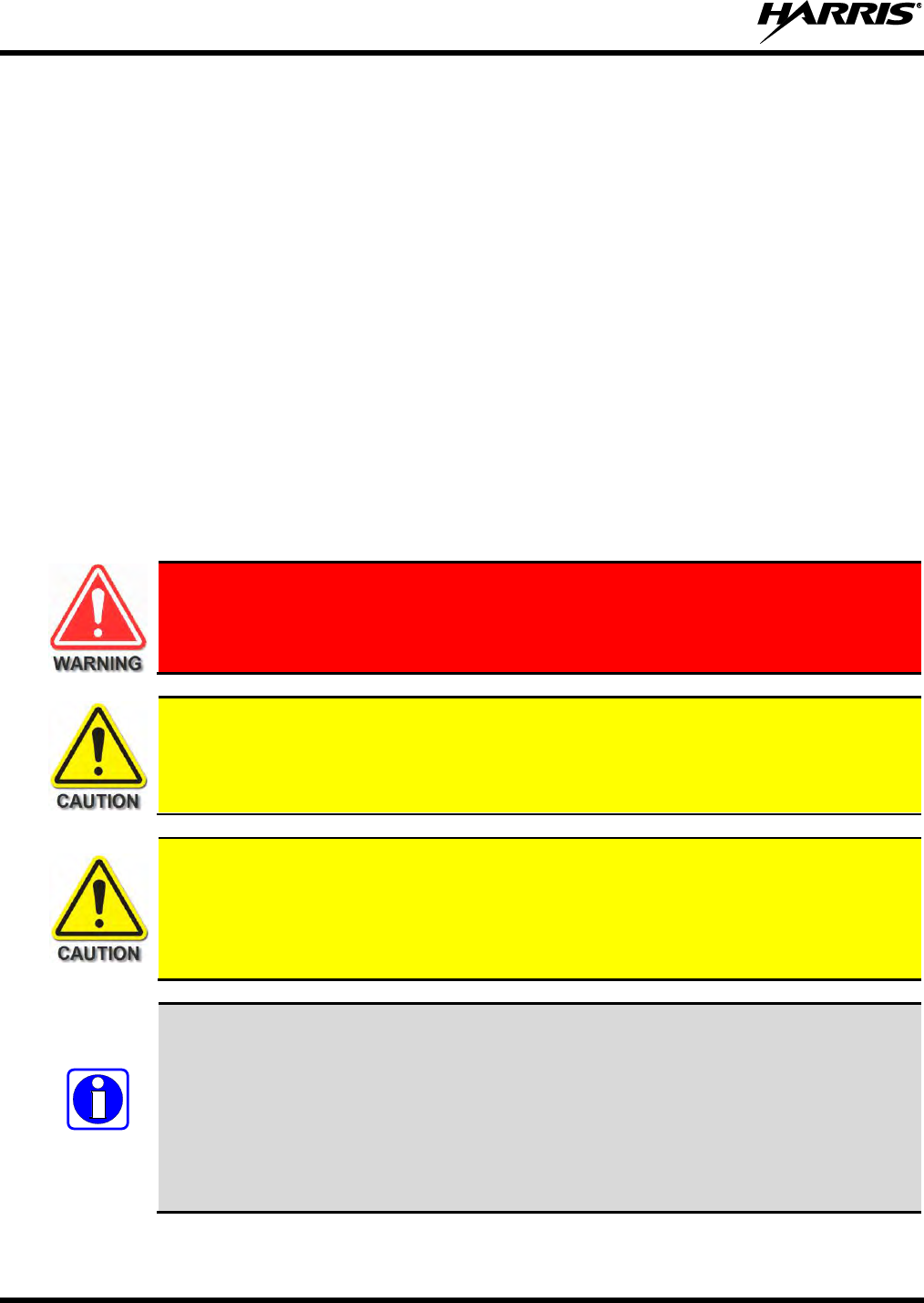
14221-1200-4010, Rev. B
78
17. PERFORMANCE TESTS
This section includes procedures to verify the performance of the installation’s antennas.
Procedures to Verify Multiband Antenna System:
Transmitting into a 50-Ohm RF Load/Terminator (“Dummy Load”) - Section 17.2 - This test verifies
the radio’s RF output power is satisfactory.
Transmitting into Mobile Antenna - Section 17.3 - This test verifies the radio’s multiband antenna
system is satisfactory.
Procedures to Verify Low Band Antenna System:
Transmitting into a 50-Ohm RF Load/Terminator (“Dummy Load”) - Section 17.4 - This test verifies
the LBPA’s RF output power is satisfactory.
Transmitting into Mobile Antenna - Section 17.5 - This test verifies the radio’s Low Band antenna
system is satisfactory.
If the vehicle’s engine must remain running, the vehicle location should be well
ventilated so exhaust fumes from the engine do not cause harm!
When jump-starting a vehicle equipped with a Unity mobile and Low Band Power
Amplifier remove the radio installation’s four (4) fuses from the fuse holders prior to jump-
starting. This will prevent possible damage to the Unity mobile, Low Band Power
Amplifier, or control head.
The accuracy of test results depends upon a DC power source in the range of 13.6 volts DC
10%, with a current capacity of greater than 20 amps for the 50-Watt MRU radios, and
greater than 25 amps for the 100-Watt VHF amplifier. Make sure the vehicle’s battery is
fully charged by running the engine for a few minutes before the test, and keep the engine
running during the test procedures.
Prior to installation, transmit RF output power levels should be configured appropriately.
The wide range of power levels indicated in the following procedures take into account such
things as: customer’s requirements; measurement errors, especially to include uncalibrated
equipment; cabling losses; and temperature variations. By no means should the result from
Performance Testing in this section be construed as the exact value of power level outputs
from the mobile radio equipment, as values are set and more accurately measured in the
factory. The values obtained in these test procedures determine a successful installation
only.
NOTE
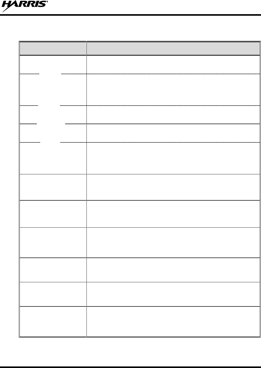
14221-1200-4010, Rev. B
79
17.1 REQUIRED TEST EQUIPMENT
Table 17-1: Test Equipment Required for Performance Tests
TEST EQUIPMENT
MODEL / PART NUMBER & DESCRIPTION
Peak-Reading Analog
Wattmeter
Bird Electronic Corp. Model 4314B (or equivalent) with Type N female
connectors at input and output ports.
Wattmeter
Element
(for MRU Tests)
Bird Electronic Corp. Element 100E, 100-watt, 400 - 1000 MHz (or
equivalent).
Bird Electric Corp. Element 10C, 10-watt, 100 - 250 MHz (or equivalent).
Use with 20 dB attenuator for VHF radio testing.
Wattmeter Element
(for low band PA Tests)
Bird Electronic Corp. Element 5A, 5-watt, 25 - 60 MHz (or equivalent).
Digital Wattmeter
Bird Electronics Corp Model 5000-EX or 5000-XT.
Wideband Power
Sensor(s)
Bird Electronics Corp Model 5012A, 350 MHz to 4000 MHz Range, 150
watts average (maximum) or equivalent.
Bird Electronics Corp Model 5017, 25 MHz to 1000 MHz Range, 500
watts average (maximum) or equivalent.
RF Attenuator,
20 dB, 150-Watt
(Only Required for
VHF Radio)
Bird Tenuline® Series Part Number 150-SA-MFN-20.
RF Coaxial
Test Cable
(Only Required for
VHF Radio)
Pasternack Enterprises PE3714-36 (or equivalent) 50-Ohm RF Coaxial
Cable with Type N female connector and Type N male connector,
approximately three (3) feet in length. The cable must have VSWR below
1.5:1 within the RF passband.
RF Coaxial
Test Cable
Pasternack Enterprises PE3661-36 (or equivalent) 50-Ohm Coaxial
Cable with TNC male connector and Type N male connector,
approximately three (3) feet in length. The cable must have VSWR below
1.5:1 within the RF passband.
Type N Male-to-TNC
Female RF Adapter
Pasternack Enterprises PE9090 or Amphenol Connex 242130 (or
equivalent) Type N male to TNC female adapter. Required to connect the
cable of the vehicle-mounted antennas to the wattmeter.
Type N Female-to-TNC
Male RF Adapter
Pasternack Enterprises PE9089 or Amphenol Connex 242131 (or
equivalent) Type N female to TNC male adapter. Required to connect a
female TNC connector to a 50-ohm RF load/terminator.
Two (2)
50-Ohm RF
Loads/Terminators
(“Dummy Loads”)
Pasternack Enterprises PE6106 (or equivalent) 50-ohm RF terminator
rated at greater than 50 watts power, with Type N male connector. Two
50-ohm RF terminators are required.
with
and
- OR -
with
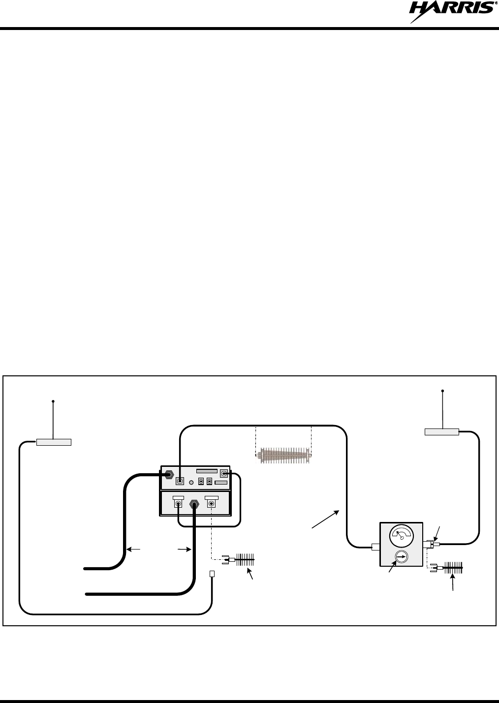
14221-1200-4010, Rev. B
80
17.2 MRU TRANSMITTING INTO A 50-OHM LOAD/TERMINATOR
1. Turn off the Unity mobile radio.
2. At the rear of the MRU, disconnect the antenna cable from the antenna connector (TNC connector
labeled “MB ANT”).
3. If it is not already, label this cable as the “MRU Antenna” cable. This should be the cable from the
highest (vehicle rooftop-mounted) antenna.
4. Using the Type N male to TNC male coaxial test cable, connect the antenna connector on the rear of
the MRU (connector labeled “MB ANT”) to the wattmeter’s input connector. Refer to Figure 17-1 as
necessary.
5. Connect a 50-ohm RF load/terminator to the wattmeter’s output connector.
6. At the rear of the LBPA, disconnect the antenna cable from the LBPA. If not labeled already, label
this antenna cable as the “LBPA Antenna” cable. This should be the cable from the lowest (vehicle
trunk lid-mounted) antenna.
7. Connect the other 50-ohm RF load/terminator to the LBPA (connector labeled “ANTENNA”). Use
the Type N female to TNC male RF adapter. Refer to Figure 17-1 as necessary.
8. Turn on the Unity XG-100M via the control head’s on/off volume control (or externally-mounted
switch).
IN OUT
Rear View of XG-100M
and XG-100LPA
DC Power
Cables
From 13.6-Volt Fused
Power Source
TNC Male-to-Type N Male
RF Coaxial Test Cable
CAN Cable and GPS
Antenna Cable connections
not are indicated.
Vehicle-Mounted
Antenna for
Multi-Band
(highest antenna)
Type N Male-to-
TNC Female
RF Adapter
Peak-
Reading
Wattmeter
50-Ohm RF Load/
Terminator
(“Dummy Load”)
Wattmeter
Element
(see text)
RADIO ANTENNA
Antenna’s
Coaxial
Cable
For XG-100M Multi-Band
coax cable connection is
made to MB ANT (TNC)
connector on rear of radio.
Vehicle-Mounted
Low Band Antenna
(lowest antenna)
50-Ohm RF Load/
Terminator
(“Dummy Load”)
Antenna’s
Coaxial
Cable 20 dB RF Attenuator
(Only Required for
50 and 110-Watt VHF Radios)
(For the 50 and 100-Watt VHF
Radios, see the Required Test
Equipment table for RF cable
requirements.)
Figure 17-1: Wattmeter Connections for Unity mobile MRU Antenna Tests
14221-1200-4010, Rev. B
81
9. Set the radio to test a conventional channel.
It is recommended that a Conventional RF channel be allocated for this testing. This same
channel should be used during the antenna test procedure presented in the next section.
If possible, use a test channel in the approximate center of the respective RF band.
10. Insert the 100-watt element into the wattmeter and position the element to measure forward RF
output power. Rotate it as necessary.
The arrow on the face of the element must point away from the XG-100M antenna jack and towards
the 50-ohm load/terminator for forward power measurements.
11. Set the wattmeter to measure peak RF power.
12. Key the MRU transmitter via the microphone’s PTT button.
Transmit only for as long as needed to take the measurement, then immediately disable the
transmission.
13. For an 800 MHz band transmission, compare the wattmeter’s reading with the target RF output power
range of between 22.1 and 55.5 watts (35 watts ±2 dB). This transmit output power range assumes
the Unity mobile is currently configured for high-power transmit.
For a 700 MHz band transmission, compare the wattmeter’s reading with the target RF output power
range of between 15.1 and 23.9 watts (19 watts ±1 dB). This transmit output power range assumes
the Unity mobile is currently configured for high-power transmit.
For a 50-Watt VHF or UHF band transmission, compare the wattmeter’s reading with the target RF
output power range of between 39.8 and 63 watts (50 watts ±1 dB). This transmit output power range
assumes the Unity mobile is currently configured for high-power transmit.
As stated in the NOTE on page 78, the wide power level range errors may be caused by test
cable loss, etc.
14. If the wattmeter reading is within the range, record the measured value in the appropriate space on
the data collection form near the end of this manual (page 90).
If the wattmeter reading is outside the range, verify the power source voltage (i.e., battery voltage)
is within the specified range, recheck all connections and measure the RF output power again. If this
fails to produce a reading within the range, replace the radio and repeat this procedure. If problems
persist, contact the Technical Assistance Center (see page 21).
15. Un-key the transmitter by releasing the microphone’s PTT button.
NOTE
NOTE
NOTE
14221-1200-4010, Rev. B
82
17.3 MRU TRANSMITTING INTO ITS ANTENNA
1. To verify transmit output power of the MRU, perform the test procedure presented in the previous
section (Section 17.2).
2. Turn off the XG-100M mobile radio.
3. Disconnect the 50-ohm load/terminator from the wattmeter.
4. Connect the cable from the vehicle-mounted MRU antenna (cable labeled “MRU Antenna”) to the
wattmeter’s output connector, as shown in Figure 17-1.
5. Turn on the radio via the control head’s on/off volume control (or externally-mounted switch). The
radio powers-up.
When transmitting into an antenna, always observe and follow all RF exposure-related
safety information presented in the Product Safety Manual.
6. Set the XG-100M to test a conventional channel. Recommend using the same channel that was used
when performing the previous procedure.
It is recommended that a test conventional channel be allocated for this testing. Otherwise,
interference with other radio users in the system may occur. Also, during transmissions,
always observe the RF exposure-related safety information presented in Section 1.2 of
this manual (begins on page 7).
7. No change in the position of the wattmeter element should be necessary. The arrow on the face of the
element must be pointing away from the MRU and towards the antenna for forward power
measurements.
8. Set the wattmeter to measure peak RF power.
9. Key the transmitter via the microphone’s PTT button.
Transmit only for as long as needed to take the measurement, then immediately disable the
transmission.
10. For an 800 MHz band transmission, compare the wattmeter’s reading with the target RF output power
range of between 22.1 and 55.5 watts (35 watts ±2 dB). This transmit output power range assumes
the Unity mobile is currently configured for high-power transmit.
For a 700 MHz band transmission, compare the wattmeter’s reading with the target RF output power
range of between 15.1 and 23.9 watts (19 watts ±1 dB). This transmit output power range assumes
the Unity mobile is currently configured for high-power transmit.
For a 50-Watt VHF and UHF band transmission, compare the wattmeter’s reading with the target RF
output power range of between 39.8 and 63 watts (50 watts ±1 dB). This transmit output power range
assumes the Unity mobile is currently configured for high-power transmit.
NOTE
NOTE
14221-1200-4010, Rev. B
83
As stated in the NOTE on page 78, the wide power level range takes into account errors
caused by test cable loss, etc.
11. If the wattmeter reading is within the range, record the value in the appropriate space on the data
collection form near the end of this manual (page 90).
If the wattmeter reading is outside the range, verify the MRU power supply voltage (i.e., battery
voltage) is within the specified range, recheck all connections, and measure the forward power again.
If this fails to produce a reading within the range, check all cabling and connections, and repeat the
testing procedure to this point. In the event the wattmeter reading still falls outside the range, replace
the antenna, make sure all connections are seated firmly, and repeat the testing procedure. If problems
persist, contact the Technical Assistance Center (see page 21).
12. Position the wattmeter’s element to measure reverse (reflected) RF power from the antenna. The
arrow on the face of the element must point away from the antenna and towards the MRU to measure
reverse power.
13. Key the transmitter via the microphone’s PTT button.
Transmit only for as long as needed to take the measurement, then immediately disable the
transmission.
14. Compare the wattmeter reading with the RF power output range of 15 watts or less. This limit exists
because the multi-band (untuned) antenna has a VSWR of 3:1.
15. If the wattmeter reading is within the range, record the value in the appropriate space on the data
collection form near the end of this manual (page 90).
If the wattmeter reading is outside the range, make sure the antenna is consistent with the specified
frequency range of the MRU. Recheck all antenna connections, and measure the reverse power again.
If this fails to produce a reading within the range, replace the antenna and repeat the entire antenna
test procedure. Any value exceeding the maximum allowable reflected power value will result in a
diminished RF output signal. If problems persist, contact the Technical Assistance Center (see see
page 21).
16. Un-key the transmitter by releasing the microphone’s PTT button.
17. Disconnect the coaxial cable jumper and wattmeter.
18. Permanently connect the MRU Multi-band antenna cable to the MB ANT (TNC) connector on the
rear of the radio.
Improper installation of the RF cables may lead not only to poor radio performance
but also to harmful exposure to RF electromagnetic energy.
NOTE
NOTE

14221-1200-4010, Rev. B
84
19. Use a pair of soft-jaw pliers to gently tighten this connection. Do not over tighten and do not twist the
antenna cable.
To prevent RF leakage and ensure peak performance, make sure the RF connectors are tight,
but do not over-tighten so connector damage will not occur.
20. Make several test calls on the radio system to verify MRU operation. Before making the calls, select
another conventional channel(s), as required to verify operation.
NOTE
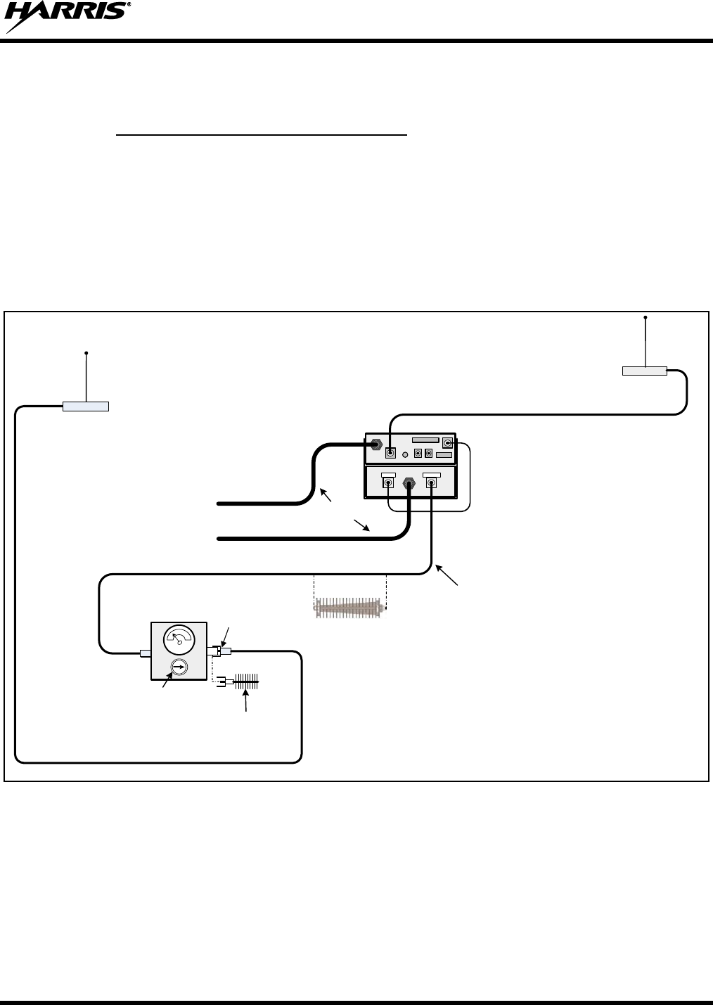
14221-1200-4010, Rev. B
85
17.4 LOW BAND PA TRANSMITTING INTO A 50-OHM LOAD/TERMINATOR
17.4.1 For a 100 Watt Output Configuration
1. If it is not already, disconnect the LBPA antenna cable at the rear of the LBPA. Label this cable from
the antenna as the “LBPA Antenna” cable. This should be the cable from the lowest (vehicle trunk lid
mounted) antenna.
2. Using the Type N male to TNC male coaxial test cable, connect the ANTENNA connector at the rear
of the LBPA to the input of the 20 dB RF Attenuator.
3. Connect a Type N male to Type N male to the wattmeter’s input connector. See Figure 17-2.
Rear View of XG-100M
and XG-100LPA
DC Power
Cables
From 13.6-Volt Fused
Power Source
TNC Male-to-Type N Male
RF Coaxial Test Cable
CAN Cable and GPS
Antenna Cable connections
not are indicated.
Vehicle-Mounted
Antenna for
Multi-Band
(highest antenna)
RADIO ANTENNA
Antenna’s
Coaxial
Cable
For XG-100M Multi-Band coax cable
connection is made to MB ANT
(TNC) connector on rear of radio.
Vehicle-Mounted
Low Band Antenna
(lowest antenna)
Antenna’s
Coaxial Cable
IN OUT
Type N Male-to-
TNC Female
RF Adapter
Peak-
Reading
Wattmeter
50-Ohm RF Load/
Terminator
(“Dummy Load”)
Wattmeter Element
(shown positioned for forward
power measurements; see text)
For XG-100LPA Low Band coax cable
connection is made to ANTENNA
(TNC) connector on rear of Amplifier.
20 dB RF Attenuator
(Only Required for
50 and 100-Watt VHF Radios)
(For the 50 and 100-Watt VHF
Radios, see the Required Test
Equipment table for RF cable
requirements.)
Figure 17-2: Wattmeter Connections for LBPA Antenna Tests
4. Connect a 50-ohm RF load/terminator to the wattmeter’s output connector.
5. Insert a 5-watt element into the wattmeter and position the element to measure forward RF output
power. Rotate it as necessary. The arrow on the face of the element must point away from the LBPA
and towards the 50-ohm load/terminator for forward power measurements.
6. Set the wattmeter to measure peak RF power.
14221-1200-4010, Rev. B
86
7. Turn on the XG-100M mobile radio, if not already on, via the control head’s on/off volume control
(or externally-mounted switch). Refer to the operator’s manual as necessary.
8. Switch the XG-100M mobile radio to a VHF low band analog channel.
9. Key the transmitter via the microphone’s PTT button.
Transmit only for as long as needed to take the measurement, then immediately disable the
transmission.
10. Compare the wattmeter’s reading with the target RF output power range of between 0.9
and 1.2 watts (100 watts ±1 dB).
This transmit output power range assumes the LBPA is currently configured for maximum transmit
power. The LBPA may be configured with a lower RF output power (30 watts) per its MRU
configuration.
For the LBPA, because a 20 dB RF attenuator used, any measurement from the wattmeter
must be multiplied by 100 to obtain the radio’s actual output power in watts.
11. If the wattmeter reading is within the range, record the measured value in the appropriate space on
the data collection form near the end of this manual (page 90).
If the wattmeter reading is outside the range, verify the MRU’s and PBPA’s power source voltage
(i.e., battery voltage) is within the specified range, recheck all connections and measure the RF output
power again. If this fails to produce a reading within the range, replace the units and repeat this
procedure. If problems persist, contact the Technical Assistance Center (see page see page 21).
12. Un-key the transmitter by releasing the microphone’s PTT button.
NOTE
NOTE
14221-1200-4010, Rev. B
87
17.5 LOW BAND PA TRANSMITTING INTO ITS ANTENNA
1. To verify transmit output power of the LBPA, perform the test procedure presented in the previous
section (Section 17.4).
2. Disconnect the 50-ohm load/terminator from the wattmeter.
3. Connect the cable from the vehicle-mounted LBPA antenna (cable labeled “LBPA Antenna”) to the
wattmeter’s output connector. See Figure 17-2.
4. Insert a 5-watt element into the wattmeter and position the element to measure forward RF output
power. Rotate it as necessary. The arrow on the face of the element must point away from the LBPA
and towards the antenna for forward power measurements.
5. Insert the 20 dB attenuator between the LBPA and the Wattmeter.
6. Set the wattmeter to measure peak RF power.
7. Turn on the XG-100M mobile radio, if not already on, via the control head’s on/off volume control
(or externally-mounted switch).
When the LBPA begins transmitting, an antenna must be connected and personnel
should be at least the minimum safe distance from the antenna. Minimum safe
distances from the LBPA antenna are listed in Table 1-1 on page 9.
8. Compare the wattmeter’s reading with the target RF output power range of between 0.9
and 1.2 watts (100 watts ±1 dB).
This transmit output power range assumes the LBPA is currently configured for maximum transmit
power. The LBPA may be configured with a lower RF output power per the MRU configuration.
For the LBPA, because a 20 dB RF attenuator used, any measurement from the wattmeter
must be multiplied by 100 to obtain the radio’s actual output power in watts.
9. If the wattmeter reading is within the range, record the value in the appropriate space on the data
collection form near the end of this manual (page 90).
If the wattmeter reading is outside the range, first verify the LBPA antenna’s driven element is
properly trimmed. Before making any antenna adjustments, be sure to disable the LBPA to stop
transmitting.
Verify LBPA power source voltage (i.e., battery voltage) is within the specified range, recheck all
connections, and measure the forward power again. If this fails to produce a reading within the range,
check all cabling and connections, and repeat the testing procedure to this point. In the event the
wattmeter reading still falls outside the range, replace the antenna, make sure all connections are
seated firmly, and repeat the testing procedure. If problems persist, contact the Technical Assistance
Center (see page see page 21).
10. Turn off the MRU. The LBPA should stop transmitting immediately, as indicated by the wattmeter.
NOTE
14221-1200-4010, Rev. B
88
11. Position the wattmeter’s 5-watt element to measure reverse (reflected) RF power from the antenna.
The arrow on the face of the element must point away from the antenna and towards the LBPA to
measure reverse power.
12. Turn on the MRU.
13. The wattmeter reading should be less than ½ watt.
14. If the wattmeter reading is within the range, record the value in the appropriate space on the data
collection form near the end of this manual (page 90).
If the wattmeter reading is outside the range, first verify the LBPA antenna’s driven element is
properly trimmed. Before making any antenna adjustments, be sure to disable the LBPA to stop
transmitting. Verify LBPA power supply voltage (i.e., battery voltage) is within the specified range,
recheck all connections, and measure the forward power again. If this fails to produce a reading
within the range, check all cabling and connections, and repeat the testing procedure to this point. In
the event the wattmeter reading still falls outside the range, replace the antenna, make sure all
connections are seated firmly, and repeat the testing procedure. If problems persist, contact the
Technical Assistance Center (see page see page 21).
15. Turn off the MRU. The LBPA should stop transmitting immediately, as indicated by the wattmeter.
16. Disconnect the coaxial cable jumper and wattmeter.
17. Permanently connect the LBPA antenna cable to the ANTENNA (TNC) connector on the rear of the
LBPA.
Improper installation of the RF cables may lead not only to poor radio performance
but also to harmful exposure to RF electromagnetic energy.
18. Use a pair of soft-jaw pliers to gently tighten this connection. Do not over tighten and do not twist the
antenna cable.
To prevent RF leakage and ensure peak performance, make sure the RF connectors are tight,
but do not over-tighten so connector damage will not occur.
19. Make several test calls on the radio system to verify MRU/LBPA operation. Before making the calls,
select another conventional channel(s), as required to verify operation.
NOTE

14221-1200-4010, Rev. B
89
This page intentionally left blank.
14221-1200-4010, Rev. B
90
17.6 TEST PERFORMANCE DATA FORM
Enter the information requested on this data collection form. Clip this form and file it as a permanent record of
the tested performance of the installed XG-100M mobile radio with XG-100LPA Low Band Power Amplifier.
Clip Here
Company Performing Installation
Technician Performing Test
Date of Test
(mm/dd/yyyy)
MRU
Serial Number
LBPA Antenna
Make and Model Number
LBPA Power Into
50-Ohm Load
Watts
LBPA Forward Power
with Antenna
LBPA Reflected Power
with Antenna
Watts
Watts
LBPA
Serial Number
MRU Antenna
Make and Model Number
Watts
RF Band
VHF
UHF
700 MHz
800 MHz
Tx Power into
50-Ohm Load
Watts
RF Band
Watts
RF Band
VHF
VHF
UHF
UHF
700 MHz
700 MHz
800 MHz
800 MHz
Forward Tx Power
with Antenna
Reflected Tx Power
with Antenna

14221-1200-4010, Rev. B
91
This page intentionally left blank.

14221-1200-4010, Rev. B
92
18. COMPLETE THE INSTALLATION
Double-check the following items before considering the installation completed:
Verify all newly installed mechanical hardware is mounted securely and all respective mounting
hardware is tight.
Verify all electrical interconnections are connected properly and the associated connector attachment
hardware is tight. Pay special attention to all RF antenna cables!
Verify all related fuses are correctly installed, properly rated, and correctly labeled.
Verify all electrical cables and wiring are tied, stowed, and protected so they are out of the way of
casual contact, away from sources of extreme heat, and wire chafing cannot occur. Pay special
attention to all RF antenna cables!
To prevent fumes from entering the vehicle’s passenger compartment, seal the hole/grommet/wire
combination at the firewall with a silicon-based sealer.
Verify all vehicle components are properly reinstalled such as kick panels, headliners, and seats.
If the installation includes a separately-mounted on/off power switch for manually turning the mobile
radio (and possibly others systems) on and off, verify it is labelled accordingly. For example: “Radio
ON/OFF.”
Remove all tools and unused hardware from the vehicle.
Verify the test performance data has been recorded on the data collection form shown in this manual.
Consult with the radio system administration personnel and placard/post required minimum antenna
separation distances in plain view of all Unity mobile user/operator positions.
19. WARRANTY REGISTRATION
Please register this product within 10 days of purchase. Registration validates the warranty coverage, and
enables Harris to contact you in case of any safety notifications issued for this product.
Registration can be made on-line at the Customer Care center webpage:
http://www.pspc.harris.com/Service/Customerservice.aspx.
While on the webpage, please review the applicable battery and/or product warranty literature.
14221-1200-4010, Rev. B
93
20. CLEANING THE RADIO EQUIPMENT
Keep the exterior of the radio and its accessories clean. Periodically clean them using one of the following
procedures:
20.1 LIGHT-DUTY CLEANING PROCEDURE
The following general cleaning procedure is recommended for light-duty cleaning:
1. To remove excess dust and dirt from the radio equipment, first brush the equipment with a dry soft-
bristle brush.
2. Remove any remaining dust and dirt using a soft clean cloth dampened with a solution of mild
detergent soap and warm water. Mix at a ratio of 1 ounce of detergent to at least 4 cups of water.
3. Follow-up by wiping the equipment with a soft clean cloth dampened with only clean warm water.
4. Finish by wiping the equipment dry with clean dry cloth.
20.2 HEAVY-DUTY CLEANING PROCEDURE
The use of the following cleaning product is recommended for heavy-duty cleaning:
Chemtronics® Electro-Wash® PR (ES1603)
Do not use other chemical cleaners, sprays, or any petroleum-based products. They may
damage the radio housing, display, knob, and/or button surfaces.
Always follow all of the manufacture’s recommendations when using any cleaning
product/solution. This includes, but is not limited to, ensuring the work area is properly
ventilated and be sure to wear safety glasses or goggles.
Use this cleaning procedure:
1. Turn off radio via the control head’s on/off/volume control.
2. Remove radio’s main power fuse and the control head’s ignition power fuse. Mark the two fuses so
they can be re-installed into their original locations later.
3. To remove excess dust and dirt from the radio equipment, first brush the equipment with a clean dry
soft-bristle brush.
4. Apply the cleaning solution to a soft clean cloth. To prevent excessive vapor concentrations, be sure
the surrounding area is well-ventilated. Do not spray any cleaning product directly on the radio
equipment.
5. Wipe the radio clean with the dampened cloth. Always apply the cleaning solution to a soft clean
cloth, and then use the dampened cloth to wipe the equipment clean.
6. Wipe off the radio equipment with clean damp cloth using mild warm soapy water.
7. Follow-up by wiping the equipment with a clean cloth dampened with only clean warm water.
8. Finish by wiping the equipment dry with clean dry cloth.
9. Re-install the two fuses into their original locations.

14221-1200-4010, Rev. B
94
(This page is intentionally blank
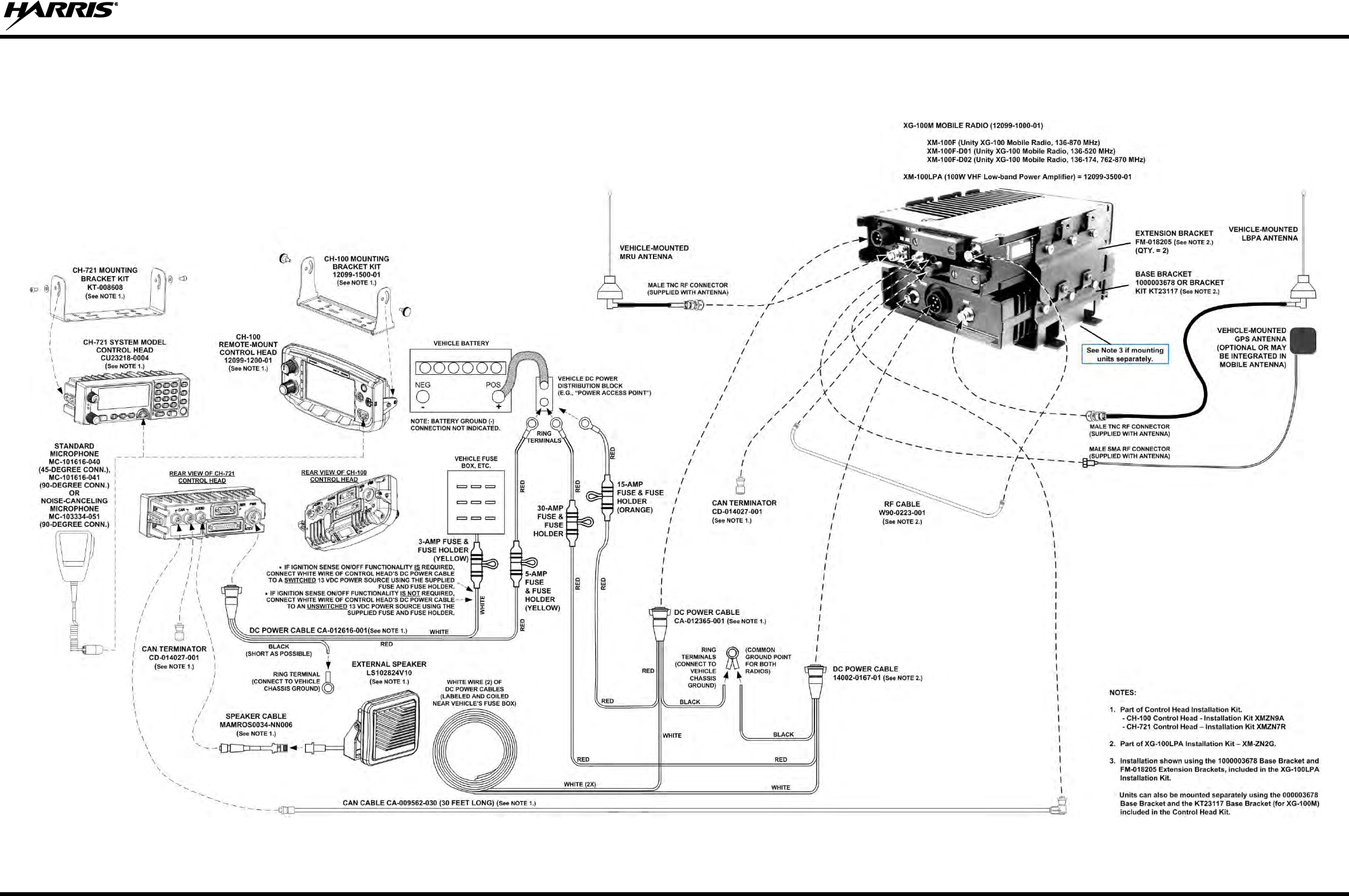
14221-1200-4010, Rev. B
95
21. WIRING DIAGRAM
UNITY MOBILE and LOW-POWER AMPLIFIER
WIRING DIAGRAM

Public Safety and Professional Communications | www.pspc.harris.com
221 Jefferson Ridge Parkway | Lynchburg, VA USA 24501 | 1-800-528-7711
Wiring Diagram Inside

Product Safety Manual
14221-1200-4000
Rev. E, Jan/15
UNITY® XG-100M and XG-100LPA
Full-Spectrum Front and
Remote-Mount Mobile Radios
Includes CH-100 Control Head,
CH-721 Scan and System Control Heads,
and HHC-731 Hand-Held Controller
This manual contains important safety information regarding specific absorption rate
(SAR) and RF exposure limits included in United States and international standards.
Read the information in this manual before operating your radio.
14221-1200-4000, Rev. E
2
MANUAL REVISION HISTORY
REV.
DATE
REASON FOR CHANGE
D
Jan/15
Added XG-100LPA VHF Low Band Power Amplifier.
E
Jan/15
Corrected Industry Canada Standard reference and deleted AN-025127-100 antenna
option.
Harris Corporation, Public Safety and Professional Communications (PSPC) Business, continually evaluates its technical
publications for completeness, technical accuracy, and organization. You can assist in this process by submitting your
comments and suggestions to the following:
Harris Corporation fax your comments to: 1-434-455-6851
PSPC Business or
Technical Publications e-mail us at: PSPC_TechPubs@harris.com
221 Jefferson Ridge Parkway
Lynchburg, VA 24501 ACKNOWLEDGEMENT
This device is made under license under one or more of the following US patents: 4,590,473; 4,636,791; 5,148,482; 5,185,796;
5,271,017; 5,377,229; 4,716,407; 4,972,460; 5,502,767; 5,146,497; 5,164,986; 5,185,795; 5,226,084; 5,247,579; 5,491,772;
5,517,511; 5,630,011; 5,649,050; 5,701,390; 5,715,365; 5,754,974; 5,826,222; 5,870,405; 6,161,089; and 6,199,037 B1. DVSI
claims certain rights, including patent rights under aforementioned U.S. patents, and under other U.S. and foreign patents and
patents pending. Any use of this software or technology requires a separate written license from DVSI.
CREDITS
Harris, assuredcommunications, Unity, and EDACS are registered trademarks of, and ProVoice is a trademark of Harris
Corporation.
AMBE is a registered trademark and IMBE, AMBE+, and AMBE+2 are trademarks of Digital Voice Systems, Inc. Bird is a
registered trademark of Bird Electronic Corporation. Bluetooth is a registered trademark of Bluetooth SIG, Inc. Microsoft
and Windows are registered trademarks of Microsoft Corporation. SmartSiren is a registered trademark of Federal Signal
Corporation.
All other brand and product names are trademarks, registered trademarks, or service marks of their respective holders.
NOTICE!
The material contained herein is subject to U.S. export approval. No export or re-export is permitted without written
approval from the U.S. Government. Rated: EAR99 in accordance with U.S. Dept. of Commerce regulations 15CFR774,
Export Administration Regulations.
Information and descriptions contained herein are the property of Harris Corporation. Such information and descriptions may
not be copied or reproduced by any means, or disseminated or distributed without the express prior written permission of
Harris Corporation, PSPC Business, 221 Jefferson Ridge Parkway, Lynchburg, VA 24501.
The voice coding technology embodied in this product is protected by intellectual property rights including patent rights,
copyrights, and trade secrets of Digital Voice Systems, Inc. The user of this technology is explicitly prohibited from
attempting to decompile, reverse engineer, or disassemble the Object Code, or in any other way convert the Object Code into
human-readable form.
Repairs to this equipment should be made only by an authorized service technician or facility designated by the supplier. Any
repairs, alterations or substitutions of recommended parts made by the user to this equipment not approved by the
manufacturer could void the user's authority to operate the equipment in addition to the manufacturer's warranty.
This product conforms to the European Union WEEE Directive 2012/19/EU. Do not dispose of this product in a
public landfill. Take it to a recycling center at the end of its life.
This manual is published by Harris Corporation without any warranty. Improvements and changes to this manual necessitated by typographical errors,
inaccuracies of current information, or improvements to programs and/or equipment, may be made by Harris Corporation at any time and without notice.
Such changes will be incorporated into new editions of this manual. No part of this manual may be reproduced or transmitted in any form or by any means,
electronic or mechanical, including photocopying and recording, for any purpose, without the express written permission of Harris Corporation.
Copyright© 2011 – 2015, Harris Corporation

14221-1200-4000, Rev. E
3
TABLE OF CONTENTS
Section Page
1 REGULATORY AND SAFETY INFORMATION .................................................................... 5
1.1 SAFETY SYMBOL CONVENTIONS ................................................................................................. 5
1.2 RF ENERGY EXPOSURE AWARENESS AND CONTROL INFORMATION FOR FCC
OCCUPATIONAL USE REQUIREMENTS........................................................................................ 5
1.2.1 Federal Communications Commission Regulations ............................................................... 6
1.3 COMPLIANCE WITH RF EXPOSURE STANDARDS ...................................................................... 6
1.3.1 Mobile Mobile Antennas ........................................................................................................ 7
1.3.2 Approved Accessories ............................................................................................................ 7
1.3.3 Contact Information ................................................................................................................ 7
1.4 REGULATORY APPROVALS ........................................................................................................... 9
1.4.1 Applicable Type Acceptance/Certification Numbers ............................................................. 9
1.4.2 FCC Part 15 ............................................................................................................................ 9
1.4.3 Industry Canada .................................................................................................................... 10
1.5 OCCUPATIONAL SAFETY GUIDELINES AND SAFETY TRAINING INFORMATION ........... 10
1.6 COMMON HAZARDS ...................................................................................................................... 10
1.7 SAFE DRIVING RECOMMENDATIONS ........................................................................................ 11
1.8 OPERATING RULES AND REGULATIONS .................................................................................. 11
1.9 OPERATING TIPS ............................................................................................................................. 12
2 RENSEIGNEMENTS SUR LA RÉGLEMENTATION ET SÉCURITÉ ............................... 13
2.1 CONVENTIONS SUR LES SYMBOLES DE SÉCURITÉ ................................................................ 13
2.2 RENSEIGNEMENTS SUR UNE EXPOSITION À L’ÉNERGIE DES RF ........................................ 13
2.2.1 Renseignements Sur Le Contrôle Et La Sensibilisation À L’énergie Des RF Pour Les
Exigences D’une Utilisation Professionnelle De La FCC .................................................... 13
2.2.2 Règlements de la Federal Communications Commission (« Commission fédérale des
communications » aux États-Unis) ....................................................................................... 14
2.3 CONFORMITÉ AUX NORMES D’EXPOSITION AUX RF ............................................................ 14
2.3.1 Antennes Mobiles ................................................................................................................. 17
2.3.2 Accessoires Approuvés ........................................................................................................ 17
2.3.3 Coordonnées ......................................................................................................................... 17
2.4 INTERFÉRENCE DES RADIOFRÉQUENCES ................................................................................ 18
2.4.1 Partie 15 de la FCC ............................................................................................................... 18
2.4.2 Industrie Canada ................................................................................................................... 18
2.5 RENSEIGNEMENTS SUR LA FORMATION SUR LA SANTÉ ET LA SÉCURITÉ AU
TRAVAIL ........................................................................................................................................... 18
3 RELATED PUBLICATIONS ..................................................................................................... 19
4 MARITIME FREQUENCIES .................................................................................................... 20
5 CATALOG AND PART NUMBERS ......................................................................................... 26
6 CUSTOMER SERVICE .............................................................................................................. 27
6.1 CUSTOMER CARE ........................................................................................................................... 27
6.2 TECHNICAL ASSISTANCE ............................................................................................................. 27
7 WARRANTY REGISTRATION ................................................................................................ 27
14221-1200-4000, Rev. E
4
LIST OF TABLES Page
Table 1-1: Recommended Minimum Safe Lateral Distance from a Transmitting Antenna Connected to a
Unity XG-100M Mobile Radio ...................................................................................................... 8
Table 1-2: Recommended Minimum Safe Lateral Distance from Transmitting Antenna for VHF Low Band
Antennas (XG-100LPA Transmit/Receive Antenna) .................................................................... 9
Tableau 2-1 : Distance latérale sécuritaire minimale recommandée d’une antenne de transmission branchée
sur une radio mobile XG-100M ................................................................................................... 16
Tableau 2-2 : Distance latérale sécuritaire minimale recommandée d’une antenne de transmission branchée
sur une radio mobile XG-100LPA de 33-48 MHz (VHF-LB) ..................................................... 17
Table 4-1: Maritime Frequencies ......................................................................................................................... 20
Table 5-1: Unity XG-100M Mobile Radio/CH-100/CH-721 Control Head/HHC-731 Controller Catalog
and Part Numbers ......................................................................................................................... 26
Table 5-2: Unity XG-100M Mobile Radio with XG-100LPA Catalog and Part Numbers.................................. 26
14221-1200-4000, Rev. E
5
1 REGULATORY AND SAFETY INFORMATION
1.1 SAFETY SYMBOL CONVENTIONS
The following conventions are used in this manual to alert the user to general safety precautions that must
be observed during all phases of operation, installation, service, and repair of this product. Failure to
comply with these precautions or with specific warnings elsewhere violates safety standards of design,
manufacture, and intended use of the product. Harris assumes no liability for the customer's failure to
comply with these standards.
The WARNING symbol calls attention to a procedure, practice, or the like, which,
if not correctly performed or adhered to, could result in personal injury. Do not
proceed beyond a WARNING symbol until the conditions identified are fully
understood or met.
The CAUTION symbol calls attention to an operating procedure, practice, or the like,
which, if not performed correctly or adhered to, could result in damage to the
equipment or severely degrade equipment performance.
NOTE
The NOTE symbol calls attention to supplemental information, which may improve
system performance or clarify a process or procedure.
1.2 RF ENERGY EXPOSURE AWARENESS AND CONTROL
INFORMATION FOR FCC OCCUPATIONAL USE REQUIREMENTS
Before using the two-way mobile radio, review the following important RF energy awareness and
control information and operational instructions. Comply with this information and instructions in
order to ensure compliance with RF exposure guidelines.
This radio is intended for use in occupational/controlled conditions, where users
have full knowledge of their exposure and can exercise control over their
exposure to remain below RF exposure limits. This radio is NOT authorized for
general population, consumer, or any other use.
Changes or modifications not expressly approved by Harris could void the user's
authority to operate the equipment.
This two-way radio uses electromagnetic energy in the radio frequency (RF) spectrum to provide
communications between two or more users over a distance. It uses RF energy or radio waves to send and
receive calls. RF energy is one form of electromagnetic energy. Other forms include, but are not limited
to, electric power, sunlight, and x-rays. RF energy, however, should not be confused with these other
forms of electromagnetic energy, which, when used improperly, can cause biological damage. Very high
levels of x-rays, for example, can damage tissues and genetic material.

14221-1200-4000, Rev. E
6
Experts in science, engineering, medicine, health, and industry work with organizations to develop
standards for exposure to RF energy. These standards provide recommended levels of RF exposure for
both workers and the general public. These recommended RF exposure levels include substantial margins
of protection. All two-way radios marketed in North America are designed, manufactured, and tested to
ensure they meet government-established RF exposure levels. In addition, manufacturers also recommend
specific operating instructions to users of two-way radios. These instructions are important because they
inform users about RF energy exposure and provide simple procedures on how to control it. Refer to the
following websites for more information on what RF energy exposure is and how to control exposure to
assure compliance with established RF exposure limits:
http://www.fcc.gov/oet/rfsafety/rf-faqs.html
http://www.osha.gov./SLTC/radiofrequencyradiation/index.html
1.2.1 Federal Communications Commission Regulations
Before it was marketed in the United States, the Unity XG-100M two-way mobile radio was tested to
ensure compliance with FCC RF energy exposure limits for two-way mobile radios. When two-way
radios are used as a consequence of employment, the FCC requires users to be fully aware of and able to
control their exposure to meet occupational requirements. Exposure awareness can be facilitated by the
use of a label directing users to specific user awareness information. The radio has an RF exposure
product label. Also, this Product Safety Manual and the applicable Operator’s Manual include
information and operating instructions required to control RF exposure and to satisfy compliance
requirements.
1.3 COMPLIANCE WITH RF EXPOSURE STANDARDS
The Unity XG-100M two-way mobile radio is designed and tested to comply with a number of national
and international standards and guidelines regarding human exposure to RF electromagnetic energy. This
radio complies with the IEEE and ICNIRP exposure limits for occupational/controlled RF exposure
environment at duty-cycle times of up to 50% (50% transmit, 50% receive), and it is authorized by the
FCC for occupational use. In terms of measuring RF energy for compliance with the FCC exposure
guidelines, the radio’s antenna radiates measurable RF energy only while it is transmitting (talking), not
when it is receiving (listening), or in a standby mode.
The Unity XG-100M two-way mobile radio complies with the following RF energy exposure standards
and guidelines:
United States Federal Communications Commission (FCC), Code of Federal Regulations; 47 CFR
§ 2 sub-part J.
American National Standards Institute (ANSI)/Institute of Electrical and Electronic Engineers (IEEE)
C95.1-2005.
Institute of Electrical and Electronic Engineers (IEEE) C95.1-2005.
IC Standard RSS-102, Issue 4, 2010: Spectrum Management and Telecommunications Radio
Standards Specification. Radiofrequency Exposure Compliance of Radiocommunication Apparatus
(All Frequency Bands).
14221-1200-4000, Rev. E
7
Table 1-1 for XG-100M and Table 1-2 for XG-100LPA list the recommended
minimum safe lateral distances for a controlled environment and for unaware
bystanders in an uncontrolled environment, from transmitting antennas (i.e.,
monopoles over a ground plane, or dipoles) at rated radio power for mobile radios
installed in a vehicle. Transmit only when unaware bystanders are at least the
uncontrolled recommended minimum safe lateral distance away from the transmitting
antenna.
Based on the highest radiated RF power and the highest antenna gain in antennas to be used with Unity
XG-100M or XG-100M with XG-100LPA, the distances listed are considered as safe distances for
controlled and uncontrolled environments with the Unity XG-100M mobile radio transmitting at a
maximum 50% duty cycle.
1.3.1 Mobile Mobile Antennas
The antenna(s) for the radio must be installed in accordance with the antenna installation procedures
presented in the radio’s Installation Manual. Refer to the Section 3 on page 19 for the respective
publication number. Installation guidelines presented in the Installation Manuals are limited to metal-
body motor vehicles or vehicles with appropriate ground planes.
Use only approved/supplied antenna(s) or an approved replacement antenna. Unauthorized antennas,
modifications, or attachments can cause the FCC RF exposure limits to be exceeded.
1.3.2 Approved Accessories
The radio has been tested and meets FCC RF guidelines when used with accessories supplied or
designated for use with it. Use of other accessories may not ensure compliance with the FCC’s RF
exposure guidelines, and may violate FCC regulations. For a list of approved accessories, refer to the
radio’s Installation Manual and/or the Products and Services Catalog.
1.3.3 Contact Information
For additional information on RF exposure and other information, contact Harris using one of the contact
links listed in Section 6 on page 27.
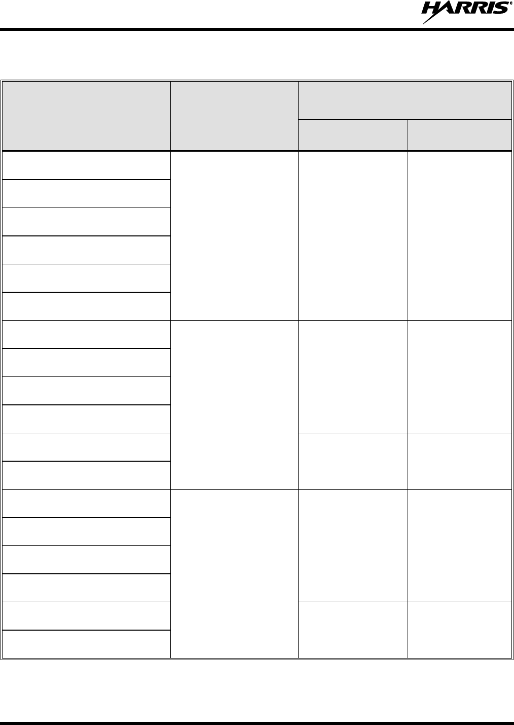
14221-1200-4000, Rev. E
8
Table 1-1: Recommended Minimum Safe Lateral Distance from a
Transmitting Antenna Connected to a Unity XG-100M Mobile Radio
ANTENNA
PART NUMBERS
RF BAND
RECOMMENDED MINIMUM LATERAL HUMAN
BODY DISTANCE FROM TRANSMITTING
ANTENNA
CONTROLLED
ENVIRONMENT
UNCONTROLLED
ENVIRONMENT
AN-125001-002 (mount) with
12099-0310-01 (element)
VHF
28.3 inches
(72 centimeters)
63.0 inches
(160 centimeters)
AN-125001-004 (mount) with
12099-0310-01 (element)
AN-125001-006 (mount) with
12099-0310-01 (element)
AN-125001-008 (mount) with
12099-0310-01 (element)
AN-125001-002 (mount) with
12099-0330-01 (element)
AN-125001-004 (mount) with
12099-0330-01 (element)
AN-125001-002 (mount) with
12099-0310-01 (element)
UHF
24.4 inches
(62 centimeters)
54.3 inches
(138 centimeters)
AN-125001-004 (mount) with
12099-0310-01 (element)
AN-125001-006 (mount) with
12099-0310-01 (element)
AN-125001-008 (mount) with
12099-0310-01 (element)
AN-125001-002 (mount) with
12099-0330-01 (element)
33.9 inches
(86 centimeters)
75.6 inches
(192 centimeters)
AN-125001-004 (mount) with
12099-0330-01 (element)
AN-125001-002 (mount) with
12099-0310-01 (element)
700/800 MHz
7.9 inches
(20 centimeters)
19.7 inches
(50 centimeters)
AN-125001-004 (mount) with
12099-0310-01 (element)
AN-125001-006 (mount) with
12099-0310-01 (element)
AN-125001-008 (mount) with
12099-0310-01 (element)
AN-125001-002 (mount) with
12099-0330-01 (element)
7.9 inches
(20 centimeters)
24 inches
(61 centimeters)
AN-125001-004 (mount) with
12099-0330-01 (element)
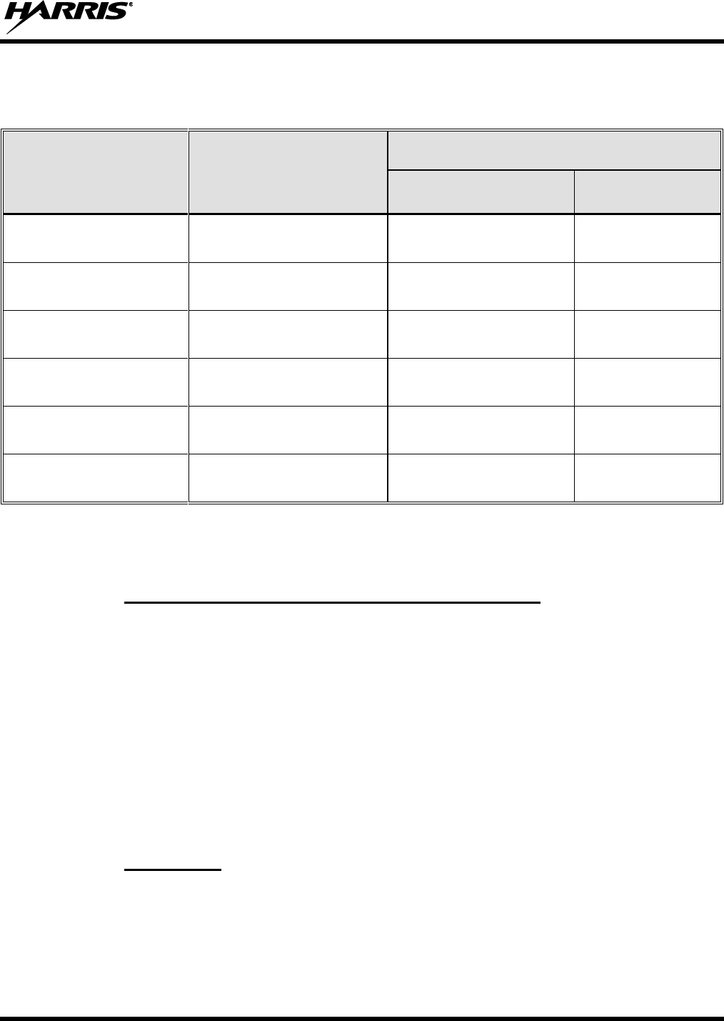
14221-1200-4000, Rev. E
9
Table 1-2: Recommended Minimum Safe Lateral Distance from Transmitting Antenna for VHF Low
Band Antennas (XG-100LPA Transmit/Receive Antenna)
(This table applies to Unity Mobile Low Band PAs only)
ANTENNA
PART NUMBER
ANTENNA DESCRIPTION
RECOMMENDED MINIMUM LATERAL HUMAN BODY
DISTANCE FROM TRANSMITTING ANTENNA
CONTROLLED
ENVIRONMENT
UNCONTROLLED
ENVIRONMENT
AN-125001-002 (mount) with
AN-025127-101 (element)
Low Band Mobile Antenna 30–35
MHz NMO DC ground
38.2 Inches
(97.0 Centimeters)
85.4 Inches
(217 Centimeters)
AN-125001-002 (mount) with
AN-025127-102 (element)
Low Band Mobile Antenna 34–37
MHz NMO DC ground
38.2 Inches
(97.0 Centimeters)
85.4 Inches
(217 Centimeters)
AN-125001-002 (mount) with
AN-025127-103 (element)
Low Band Mobile Antenna 37–40
MHz NMO DC ground
38.2 Inches
(97.0 Centimeters)
85.4 Inches
(217 Centimeters)
AN-125001-002 (mount) with
AN-025127-104 (element)
Low Band Mobile Antenna 40–47
MHz NMO DC ground
38.2 Inches
(97.0 Centimeters)
85.4 Inches
(217 Centimeters)
AN-125001-002 (mount) with
AN-025127-105 (element)
Low Band Mobile Antenna 45–48
MHz NMO DC ground
38.2 Inches
(97.0 Centimeters)
85.4 Inches
(217 Centimeters)
AN-125001-002 (mount) with
AN-025127-106 (element)
Low Band Mobile Antenna 47–50
MHz NMO DC ground
38.2 Inches
(97.0 Centimeters)
85.4 Inches
(217 Centimeters)
1.4 REGULATORY APPROVALS
1.4.1 Applicable Type Acceptance/Certification Numbers
FCC Type Acceptance:
50-Watt XG-100M: AQZ-XG-100M00
XG-100MLPA: AQZ-XG-100LPA
Applicable FCC Rules: Part 15, Part 80, and Part 90
Industry Canada Certification:
50-Watt XG-100M: 122D-XG100M00
XG-100MLPA: 122D-XG100LPA
Applicable Industry Canada Rules: RSS 119; RSS 210
1.4.2 FCC Part 15
This device complies with Part 15 of the FCC Rules. Operation is subject to the following two conditions:
1. This device may not cause harmful interference, and
2. This device must accept any interference received, including interference that may cause undesired
operation.

14221-1200-4000, Rev. E
10
1.4.3 Industry Canada
This device complies with Industry Canada license-exempt RSS standard(s). Operation is subject to the
following two conditions: (1) this device may not cause interference, and (2) this device must accept any
interference, including interference that may cause undesired operation of the device.
Le présent appareil est conforme aux CNR d'Industrie Canada applicables aux appareils radio exempts de
licence. L'exploitation est autorisée aux deux conditions suivantes : (1) l'appareil ne doit pas produire de
brouillage, et (2) l'utilisateur de l'appareil doit accepter tout brouillage radioélectrique subi, même si le
brouillage est susceptible d'en compromettre le fonctionnement.
1.5 OCCUPATIONAL SAFETY GUIDELINES AND SAFETY TRAINING
INFORMATION
To ensure bodily exposure to RF electromagnetic energy is within the FCC allowable limits for
occupational use. Always adhere to the following basic guidelines:
The push-to-talk button should only be depressed when intending to send a voice message.
The radio should only be used for necessary work-related communications.
The radio should only be used by authorized and trained personnel. It should never be operated by
children.
Do not attempt any unauthorized modification to the radio. Changes or modifications to the radio may
cause harmful interference and/or cause it to exceed FCC RF exposure limits. Only qualified
personnel should service the radio.
Always use only authorized accessories (antennas, control heads, speakers/mics, etc.). Use of
unauthorized accessories can cause the FCC RF exposure compliance requirements to be exceeded.
The information listed above provides the user with information needed to make him or her aware of a RF
exposure, and what to do to assure that this radio operates within the FCC exposure limits of this radio.
1.6 COMMON HAZARDS
The operator of any mobile radio should be aware of certain hazards common to
the operation of vehicular radio transmissions. Possible hazards include but are
not limited to:
Explosive Atmospheres — Just as it is dangerous to fuel a vehicle while its engine is running, be
sure to turn the radio OFF while fueling the vehicle. If the radio is mounted in the trunk of the
vehicle, DO NOT carry containers of fuel in the trunk.
Areas with potentially explosive atmosphere are often, but not always, clearly marked. Turn the radio
OFF when in any area with a potentially explosive atmosphere. It is rare, but not impossible that the
radio or its accessories could generate sparks.
Interference To Vehicular Electronic Systems — Electronic fuel injection systems, electronic anti-
skid braking systems, electronic cruise control systems, etc., are typical of the types of electronic
devices that can malfunction due to the lack of protection from radio frequency (RF) energy present
when transmitting. If the vehicle contains such equipment, consult the dealer for the make of vehicle
and enlist his aid in determining if such electronic circuits perform normally when the radio is
transmitting.

14221-1200-4000, Rev. E
11
Electric Blasting Caps — To prevent accidental detonation of electric blasting caps, DO NOT use
two-way radios within 1000 feet (305 meters) of blasting operations. Always obey the “Turn Off
Two-Way Radios” (or equivalent) signs posted where electric blasting caps are being used. (OSHA
Standard: 1926.900).
Radio Frequency Energy — To prevent burns or related physical injury from radio frequency
energy, do not operate the transmitter when anyone outside of the vehicle is within the minimum safe
distance from the antenna as specified in Table 1-1. Refer to Section 1.2 for additional information.
Vehicles Powered By Liquefied Petroleum (LP) Gas — Radio installation in vehicles powered by
liquefied petroleum gas, where the LP gas container is located in the trunk or other sealed-off space
within the interior of the vehicle, must conform to the National Fire Protection Association standard
NFPA 58. This requires:
The space containing the radio equipment must be isolated by a seal from the space containing
the LP gas container and its fittings.
Outside filling connections must be used for the LP gas container.
The LP gas container space shall be vented to the outside of the vehicle.
Vehicles Equipped with Airbags — For driver and passenger safety, avoid mounting the radio’s
control head (or any other component) above or near airbag deployment areas. In addition to driver-
side and passenger-side front-impact airbags, some vehicles may also be equipped with side-impact
airbags. For occupant safety, verify the location of all airbags within the vehicle before installing the
radio equipment.
1.7 SAFE DRIVING RECOMMENDATIONS
The American Automobile Association (AAA) advocates the following key safe driving recommenda-
tions:
Read the literature on the safe operation of the radio.
Keep both hands on the steering wheel and the microphone in its hanger whenever the vehicle is in motion.
Place calls only when the vehicle is stopped.
When talking from a moving vehicle is unavoidable, drive in the slower lane. Keep conversations brief.
If a conversation requires taking notes or complex thought, stop the vehicle in a safe place and
continue the call.
Whenever using a mobile radio, exercise caution.
1.8 OPERATING RULES AND REGULATIONS
Two-way radio systems must be operated in accordance with the rules and regulations of the local,
regional, or national government.
In the United States, the Unity XG-100M mobile radio must be operated in accordance with the rules and
regulations of the Federal Communications Commission (FCC). Operators of two-way radio equipment
must be thoroughly familiar with the rules that apply to the particular type of radio operation. Following
these rules helps eliminate confusion, assures the most efficient use of the existing radio channels, and
results in a smoothly functioning radio network.
When using a two-way radio, remember these rules:
It is a violation of FCC rules to interrupt any distress or emergency message. The radio operates in
much the same way as a telephone “party line.” Therefore, always listen to make sure the channel is
clear before transmitting. Emergency calls have priority over all other messages. If someone is
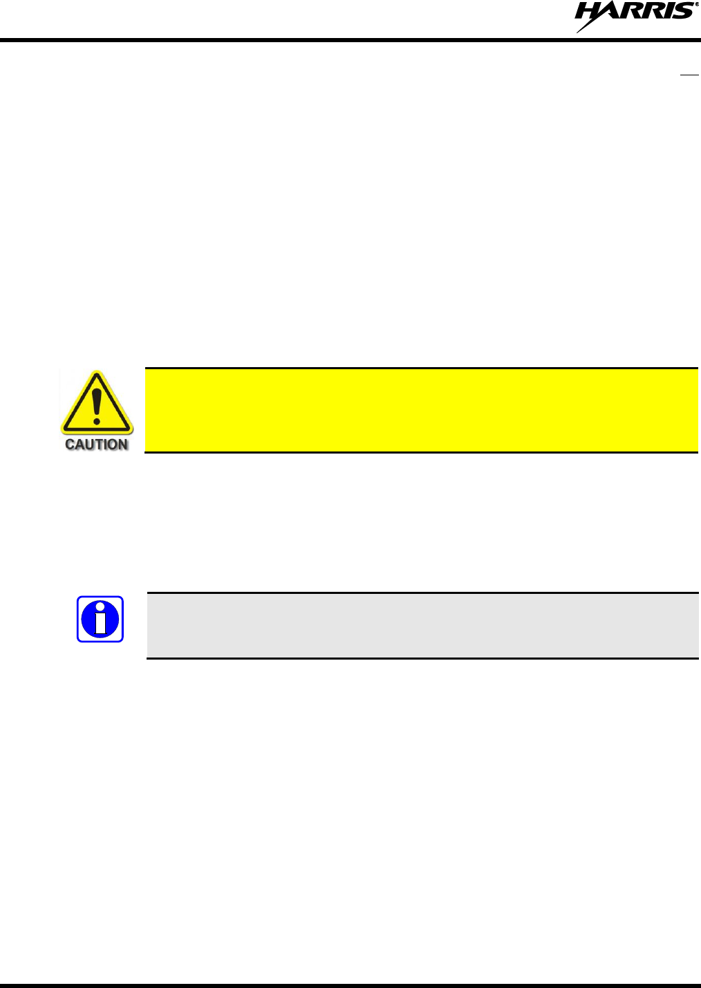
14221-1200-4000, Rev. E
12
sending an emergency message – such as reporting a fire or asking for help in an accident, do not
transmit unless assistance can be offered.
The use of profane or obscene language is prohibited by Federal law.
It is against the law to send false call letters or false distress or emergency messages. The FCC
requires keeping conversations brief and confined to business. Use coded messages whenever
possible to save time.
Using the radio to send personal messages (except in an emergency) is a violation of FCC rules. Send
only essential messages.
It is against Federal law to repeat or otherwise make known anything overheard on the radio.
Conversations between others sharing the channel must be regarded as confidential.
The FCC requires self-identification at certain specific times by means of call letters. Refer to the
rules that apply to the particular type of operation for the proper procedure.
No changes or adjustments shall be made to the equipment except by an authorized or certified
electronics technician.
Under U.S. law, operation of an unlicensed radio transmitter within the jurisdiction of
the United States may be punishable by a fine of up to $10,000, imprisonment for up to
two (2) years, or both.
1.9 OPERATING TIPS
The following conditions tend to reduce the effective range of two-way radios and should be avoided
whenever possible:
Operating the radio in areas of low terrain, or while under power lines or bridges.
Obstructions such as mountains and buildings.
In areas where transmission or reception is poor, communication improvement may
sometimes be obtained by moving a few yards in another direction, or moving to a
higher elevation.
NOTE
14221-1200-4000, Rev. E
13
2 RENSEIGNEMENTS SUR LA RÉGLEMENTATION ET
SÉCURITÉ
2.1 CONVENTIONS SUR LES SYMBOLES DE SÉCURITÉ
Les conventions suivantes sont utilisées dans le présent manuel pour avertir l’utilisateur des précautions
générales de sécurité qui doivent être observées pendant toutes les phases d’opération, d’entretien et de
réparation de ce produit. Le non-r.espect de ces précautions ou d’avertissements précisés ailleurs enfreint
les normes de sécurité de la conception, de la fabrication et de l’utilisation prévue du produit. Harris
n’assume aucune responsabilité pour le non-respect de ces normes par le client.
Le symbole MISE EN GARDE attire l’attention sur une procédure ou une
pratique qui, si elle n’est pas correctement effectuée ou observée, pourrait
entraîner une blessure personnelle. Ne pas poursuivre au-delà d’un symbole de
MISE EN GARDE avant que les conditions identifiées soient complètement
comprises ou satisfaites.
Le symbole AVERTISSEMENT attire l’attention sur une procédure ou une pratique
opérationnelle qui, si elle n’est pas correctement effectuée ou observée, pourrait
entraîner un bris d’équipement ou une importante baisse de rendement de l’équipement.
Le symbole REMARQUE attire l’attention sur des renseignements supplémentaires qui
peuvent améliorer le rendement du système ou clarifier un processus ou une procédure.
2.2 RENSEIGNEMENTS SUR UNE EXPOSITION À L’ÉNERGIE DES RF
2.2.1 Renseignements Sur Le Contrôle Et La Sensibilisation À L’énergie Des
RF Pour Les Exigences D’une Utilisation Professionnelle De La FCC
Avant d’utiliser les radios mobiles bidirectionnelles, passez en revue les renseignements et les
instructions opérationnelles importants suivants sur le contrôle et la sensibilisation à l’énergie des
RF. Se conformer à ces renseignements et instructions pour assurer la conformité aux directives
d’exposition aux RF.
Cette radio est destinée à être utilisée dans des conditions professionnelles/
contrôlées, où les utilisateurs ont une pleine connaissance de leur exposition et
peuvent exercer un contrôle sur leur exposition pour rester sous les limites
d’exposition aux RF. Cette radio N’est PAS autorisée pour la population générale,
les consommateurs ou toute autre utilisation.
Des changements ou modifications non expressément approuvés par Harris pourraient
annuler le droit d’utilisation de l’équipement pour l’utilisateur.

14221-1200-4000, Rev. E
14
Cette radio bidirectionnelle utilise une énergie électromagnétique dans le spectre des radiofréquences
(RF) pour permettre une communication à distance entre deux utilisateurs ou plus. Elle utilise l’énergie
des RF ou les ondes radio pour envoyer et recevoir des appels. L’énergie des RF est une forme d’énergie
électromagnétique. D’autres formes comprennent, entre autres, l’énergie électrique, la lumière du soleil et
les rayons X. Toutefois, l’énergie des RF ne doit pas être confondue avec ces autres formes d’énergie
électromagnétique qui, lorsque mal utilisées, peuvent causer des dommages biologiques. Par exemple, des
niveaux très élevés de rayons X peuvent endommager les tissus et le matériel génétique.
Des experts en science, en ingénierie, en médecine, en santé et de l’industrie travaillent avec des
organismes pour établir des normes pour l’exposition à l’énergie des RF. Ces normes procurent des
niveaux recommandés d’exposition aux RF autant aux travailleurs qu’au grand public. Ces niveaux
d’exposition aux RF recommandés comprennent d’importantes marges de protection. Toutes les radios
bidirectionnelles commercialisées en Amérique du Nord sont conçues, fabriquées et testées pour s’assurer
qu’elles satisfont les niveaux d’exposition aux RF établis par le gouvernement. Les fabricants
recommandent également des consignes d’utilisation particulières aux utilisateurs de radios
bidirectionnelles. Ces instructions sont importantes, car elles informent les utilisateurs sur l’exposition à
l’énergie des RF et donnent des procédures simples sur la manière de contrôler cette exposition.
Consultez les sites Web suivants (en anglais) pour de plus amples renseignements sur ce qu’est
l’exposition à l’énergie des RF et comment contrôler l’exposition pour assurer la conformité aux limites
d’exposition établies :
http://www.fcc.gov/oet/rfsafety/rf-faqs.html
http://www.osha.gov./SLTC/radiofrequencyradiation/index.html
2.2.2 Règlements de la Federal Communications Commission (« Commission
fédérale des communications » aux États-Unis)
Avant d’être mise sur le marché aux États-Unis, la radio mobile bidirectionnelle XG-100M a été testée
pour s’assurer de sa conformité aux limites d’exposition à l’énergie des RF de la FCC pour les radios
mobiles bidirectionnelles. Lorsque les radios bidirectionnelles sont utilisées à la suite d’une embauche, la
FCC demande aux utilisateurs de bien connaître et de pouvoir contrôler leur exposition pour satisfaire les
exigences professionnelles. La sensibilisation à l’exposition peut être facilitée par l’utilisation d’une
étiquette qui dirige les utilisateurs vers des renseignements particuliers sur la sensibilisation de
l’utilisateur. La radio possède une étiquette de produit sur l’exposition aux RF. De plus, le Manuel sur la
sécurité du produit et le présent Manuel de l’opérateur comprennent des renseignements et les consignes
d’utilisation nécessaires pour contrôler l’exposition aux RF et pour satisfaire les exigences de conformité.
d’utilisation nécessaires pour contrôler l’exposition aux RF et pour satisfaire les exigences de conformité.
2.3 CONFORMITÉ AUX NORMES D’EXPOSITION AUX RF
La radio mobile bidirectionnelle XG-100M est conçue et testée pour être conforme à un certain nombre
de normes et directives nationales et internationales quant à l’exposition humaine à l’énergie
électromagnétique des RF. Cette radio est conforme aux limites d’exposition de l’IEEE et de la
Commission internationale de protection contre les rayonnements non ionisants pour un environnement
professionnel/contrôlé d’exposition aux RF à des périodes de cycle de service allant jusqu’à 50 % (50 %
de transmission, 50 % de réception) et elle est autorisée par la FCC pour une utilisation professionnelle.
Sur le plan de la mesure de l’énergie des RF pour la conformité aux directives d’exposition de la FCC,
l’antenne de la radio irradie une énergie des RF mesurable seulement lorsqu’elle transmet (parler), et non
lorsqu’elle reçoit (écouter) ou en mode d’attente.
14221-1200-4000, Rev. E
15
La radio mobile bidirectionnelle XG-100M est conforme aux normes et directives d’exposition à l’énergie
des RF suivantes :
Federal Communications Commission (FCC) américaine, le Code of Federal Regulations; 47 CFR
§ 2 sous-partie J.
American National Standards Institute (ANSI)/Institute of Electrical and Electronic Engineers (IEEE)
C95.1-2005.
Institute of Electrical and Electronic Engineers (IEEE) C95.1-2005.
IC Standard RSS-102, numéro 4, 2010 : Spectrum Management and Telecommunications Radio
Standards Specification. Radiofrequency Exposure Compliance of Radiocommunication Apparatus
(All Frequency Bands).
Tableau 2-1 et Tableau 2-2 indiquent les distances latérales sécuritaires minimales
recommandées pour un environnement contrôlé et pour les spectateurs ignorants dans
un environnement non contrôlé, d’antennes de transmission (c.-à-d., des monopôles sur
un plan de sol, ou des dipôles) à une puissance de radio évaluée pour les radios mobiles
installées dans un véhicule. Ils ne transmettent que lorsque les spectateurs ignorants
sont au moins à la distance latérale sécuritaire minimale recommandée non contrôlée de
l’antenne de transmission.
Basées sur la puissance des RF irradiées la plus élevée et le gain d’antenne le plus élevé dans les antennes
à utiliser avec le XG-100M, les distances indiquées dans les Tableau 2-1 (XG-100M) et Tableau 2-2 (XG-
100LPA) sont considérées comme des distances sécuritaires pour des environnements contrôlés et non
contrôlés avec la radio mobile XG-100M qui transmet à un cycle de service maximal de 50 % :
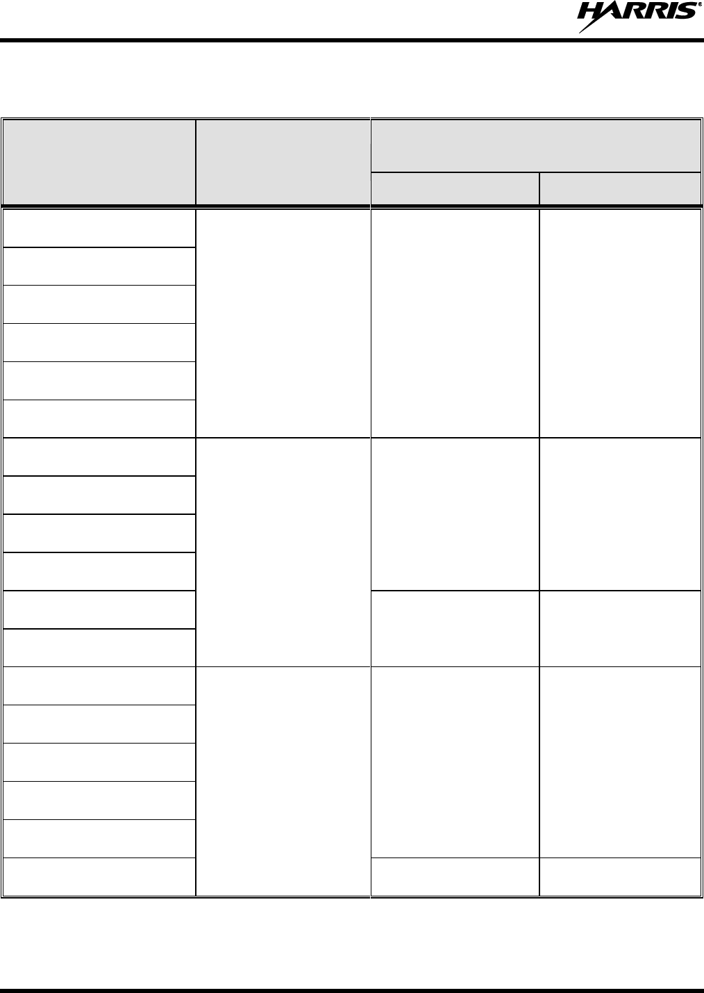
14221-1200-4000, Rev. E
16
Tableau 2-1 : Distance latérale sécuritaire minimale recommandée d’une antenne de transmission
branchée sur une radio mobile XG-100M
NUMÉRO DE PIÈCE DE
L’ÉLÉMENT DE L’ANTENNE
DESCRIPTION DE
L’ANTENNE
DISTANCE MINIMALE RECOMMANDÉE DE
L’ANTENNE DE TRANSMISSION POUR LE CORPS
HUMAIN
ENVIRONNEMENT
CONTRÔLÉ
ENVIRONNEMENT NON
CONTRÔLÉ
AN-125001-002 (monture) avec
12099-0310-01 (élément)
136 à 174 MHz (VHF)
72 centimeters
(28.3 po)
160 centimeters
(63.0 po)
AN-125001-004 (monture) avec
12099-0310-01 (élément)
AN-125001-006 (monture) avec
12099-0310-01 (élément)
AN-125001-008 (monture) avec
12099-0310-01 (élément)
AN-125001-002(monture) avec
12099-0330-01 (élément)
AN-125001-004 (monture) avec
12099-0330-01 (élément)
AN-125001-002 (monture) avec
12099-0310-01 (élément)
380 à 520 MHz (UHF)
62 centimeters
(24.4 po)
138 centimeters
(54.3 po)
AN-125001-004 (monture) avec
12099-0310-01 (élément)
AN-125001-006 (monture) avec
12099-0310-01 (élément)
AN-125001-008 (monture) avec
12099-0310-01 (élément)
AN-125001-002 (monture) avec
12099-0330-01 (élément)
86 centimeters
(33.9 po)
192 centimeters
(75.6 po)
AN-125001-004 (monture) avec
12099-0330-01 (élément)
AN-125001-002 (monture) avec
12099-0310-01 (élément)
700/800 MHz
20 centimeters
(7.9 po)
50 centimeters
(19.7 po)
AN-125001-004 (monture) avec
12099-0310-01 (élément)
AN-125001-006 (monture) avec
12099-0310-01 (élément)
AN-125001-008 (monture) avec
12099-0310-01 (élément)
AN-125001-002 (monture) avec
12099-0330-01 (élément)
AN-125001-004 (monture) avec
12099-0330-01 (élément)
20 centimeters
(7.9 po)
61 centimeters
(24 po)
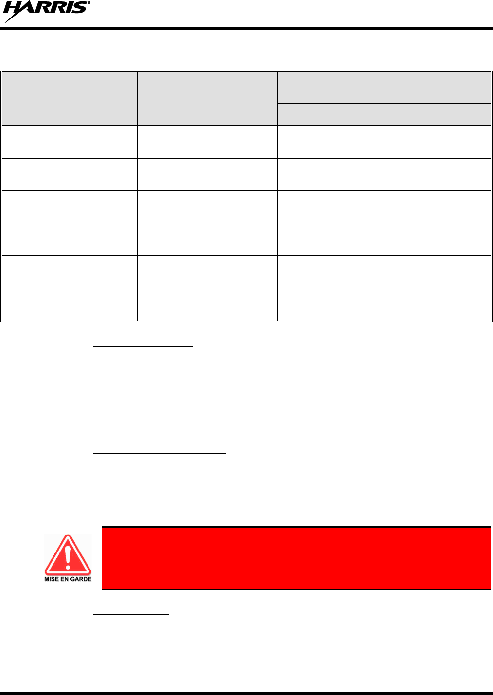
14221-1200-4000, Rev. E
17
Tableau 2-2 : Distance latérale sécuritaire minimale recommandée d’une antenne de transmission
branchée sur une radio mobile XG-100LPA de 33-48 MHz (VHF-LB)
NUMÉRO DE PIÈCE DE
L’ANTENNE
DESCRIPTION DE L’ANTENNE
DISTANCE MINIMALE RECOMMANDÉE DE
L’ANTENNE DE TRANSMISSION POUR LE
CORPS HUMAIN
ENVIRONNEMENT
CONTRÔLÉ
ENVIRONNEMENT
NON CONTRÔLÉ
AN-125001-002 (monture) avec
AN-025127-101 (élément)
Antenne Basse Band 30–35 MHz
NMO DC sol
97.0 Centimeters
(38.2 po)
217 Centimeters
(85.4 po)
AN-125001-002 (monture) avec
AN-025127-102 (élément)
Antenne Basse Band 34–37 MHz
NMO DC sol
97.0 Centimeters
(38.2 po)
217 Centimeters
(85.4 po)
AN-125001-002 (monture) avec
AN-025127-103 (élément)
Antenne Basse Band 37–40 MHz
NMO DC sol
97.0 Centimeters
(38.2 po)
217 Centimeters
(85.4 po)
AN-125001-002 (monture) avec
AN-025127-104 (élément)
Antenne Basse Band 40–47 MHz
NMO DC sol
97.0 Centimeters
(38.2 po)
217 Centimeters
(85.4 po)
AN-125001-002 (monture) avec
AN-025127-105 (élément)
Antenne Basse Band 45–48 MHz
NMO DC sol
97.0 Centimeters
(38.2 po)
217 Centimeters
(85.4 po)
AN-125001-002 (monture) avec
AN-025127-106 (élément)
Antenne Basse Band 47–50 MHz
NMO DC sol
97.0 Centimeters
(38.2 po)
217 Centimeters
(85.4 po)
2.3.1 Antennes Mobiles
Les antennes pour la radio doivent être installées conformément aux procédures présentées dans le
Manuel sur la sécurité du produit et dans le Manuel d’installation. L’installation est limitée à un ou des
véhicules motorisés en métal avec des plans au sol appropriés.
Utilisez uniquement les antennes approuvées/fournies ou une antenne de remplacement approuvée. Des
antennes, des modifications ou des accessoires non autorisés peuvent causer un dépassement des limites
d’exposition aux RF de la FCC.
2.3.2 Accessoires Approuvés
La radio a été testée et satisfait les directives de RF de la FCC lorsqu’elle est utilisée avec les accessoires
fournis ou conçus pour être utilisés avec elle. L’utilisation d’autres accessoires peut ne pas garantir la
conformité aux directives d’exposition de la FCC et peut enfreindre la réglementation de la FCC. Pour
une liste d’accessoires approuvés, consultez le Manuel d’installation ou le Catalogue de produits et
services de Harris.
Utilisez toujours des accessoires autorisés Harris (antennes, haut-parleurs/micros,
etc.). L’utilisation d’accessoires non autorisés peut entraîner un dépassement des
exigences de conformité pour une exposition aux RF professionnelle ou contrôlée
de la FCC.
2.3.3 Coordonnées
Pour de plus amples renseignements sur l’exposition aux RF ou d’autres renseignements, contactez Harris
en utilisant l’un des liens apparaissant à la Section 6.

14221-1200-4000, Rev. E
18
2.4 INTERFÉRENCE DES RADIOFRÉQUENCES
2.4.1 Partie 15 de la FCC
Cet appareil est conforme à la Partie 15 de la réglementation de la FCC. Le fonctionnement est soumis
aux deux conditions suivantes :
1. Cet appareil ne doit pas causer une interférence nuisible; et
2. Cet appareil doit accepter toute interférence reçue, y compris une interférence qui peut causer un
fonctionnement non souhaité.
2.4.2 Industrie Canada
Cet appareil est conforme aux normes RSS exemptées de licence d’Industrie Canada. Le fonctionnement
est soumis aux deux conditions suivantes : (1) cet appareil ne doit pas causer d’interférence et (2) cet
appareil doit accepter toute interférence, y compris une interférence qui peut causer un fonctionnement
non souhaité de l’appareil.
2.5 RENSEIGNEMENTS SUR LA FORMATION SUR LA SANTÉ ET LA
SÉCURITÉ AU TRAVAIL
S’assurer que l’exposition physique à l’énergie électromagnétique des RF se situe dans les limites
acceptables de la FCC pour l’utilisation professionnelle. Toujours se conformer aux directives de base
suivantes :
Le bouton de microphone doit être abaissé seulement lorsque l’on souhaite envoyer un message
vocal.
La radio doit être utilisée seulement pour les communications nécessaires liées au travail.
La radio doit être utilisée seulement par du personnel autorisé et formé. Elle ne doit jamais être
utilisée par des enfants.
Ne tentez pas d’apporter une modification non autorisée à la radio. Des changements ou des
modifications à la radio peuvent causer une interférence nocive ou entraîner un dépassement des
limites d’exposition aux RF de la FCC. Seul le personnel qualifié doit utiliser la radio.
Utilisez toujours seulement des accessoires autorisés (antennes, haut-parleurs/micros, etc.).
L’utilisation d’accessoires non autorisés peut entraîner un dépassement des exigences de conformité
pour une exposition aux RF de la FCC.
Les renseignements donnés ci-dessus donnent à l’utilisateur les renseignements nécessaires pour le
sensibiliser à l’exposition aux RF et sur ce qu’il faut faire pour s’assurer que cette radio fonctionne dans
les limites d’exposition de la FCC de cette radio.

14221-1200-4000, Rev. E
19
3 RELATED PUBLICATIONS
The following publications contain additional information about this radio equipment:
Quick Guide for Unity XG-100M Mobile Radio
with CH-100 Control Head:
14221-1200-1010
Quick Guide for Unity XG-100M Mobile Radio
with CH-721 Control Head:
14221-1200-1000
Operator’s Manual for Unity XG-100M Mobile Radio
with CH-100 Control Head:
14221-1200-2010
Operator’s Manual for Unity XG-100M Mobile Radio
with CH-721 Control Head:
14221-1200-2000
Operator’s Manual for HHC-731 Hand-Held Controller:
MM-018321-001
Installation Manual for XG-100M :
14221-1200-4440
Installation Manual for XG-100LPA
14221-1200-4010
Along with this Product Safety Manual, Quick Guides (for radio operators) are included with each mobile
radio equipment package when the package ships from the factory. The Operator’s Manuals and the
Quick Guides are also available online at http://pspc.harris.com/Products/Mobile/unitymobile.aspx
without a login. All XG-100M-related mobile radio publications can be obtained from
www.pspc.harris.com via an Information Center login (i.e., a user name and password are required). The
publications are in Tech-Link’s Technical Manual Library.
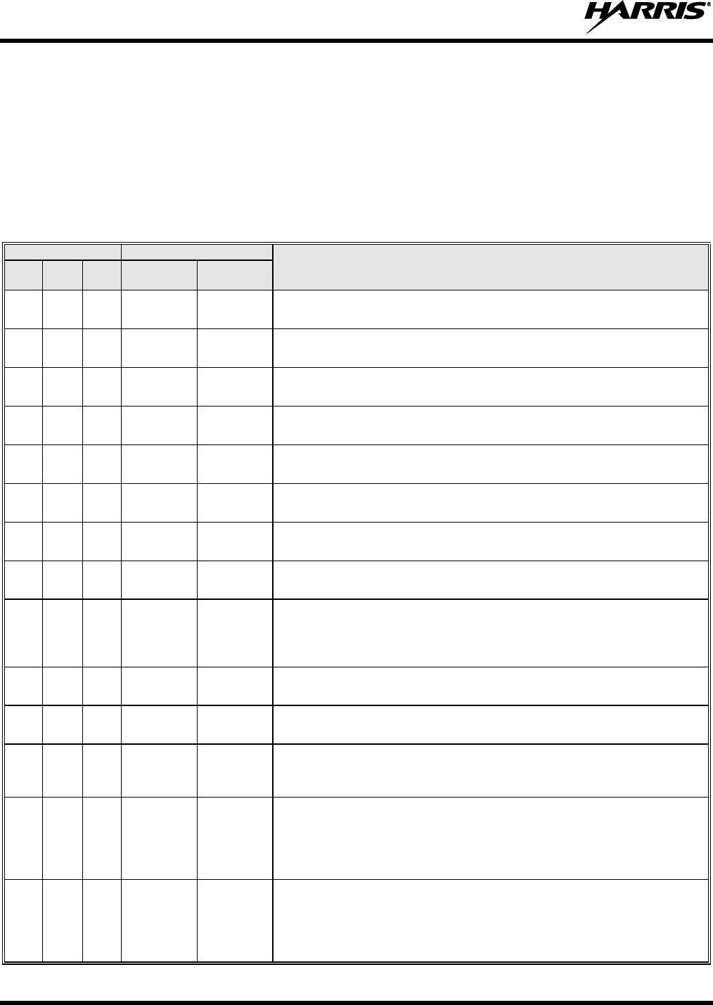
14221-1200-4000, Rev. E
20
4 MARITIME FREQUENCIES
Refer to Table 4-1 for a list of maritime frequencies per United States Coast Guard (USCG), National
Oceanic and Atmospheric Administration (NOAA), and Canadian Department Fisheries and Oceans.
United States (US)
International (Intl)
Canada (CA)
Table 4-1: Maritime Frequencies
CHANNEL
FREQUENCY
CHANNEL USAGE
US
INTL
CA
SHIP
(MHz)
SHORE
(MHz)
1
1
T: 156.05
R: 160.65
T: 160.65
R: 156.05
International: Public Correspondence, Port Operations.
1a
T/R:
156.05
T/R:
156.05
US: Port Operations and Commercial, Vessel Traffic Service (VTS). New
Orleans/Lower Mississippi area.
2
2
T: 156.10
R: 160.70
T: 160.70
R: 156.10
International: Public Correspondence, Port Operations.
3
3
T: 156.15
R: 160.75
T: 160.75
R: 156.15
International: Public Correspondence, Port Operations.
4
T: 156.20
R: 160.80
T: 160.80
R: 156.20
International: Public Correspondence, Port Operations.
4a
T/R:
156.20
T/R:
156.20
Canada: Department Fisheries Ocean (DFO)/Canadian Coast Guard only in
British Columbia coast area. Commercial fishing in east coast area.
5
T: 156.25
R: 160.85
T: 160.85
R: 156.25
International: Public Correspondence, Port Operations.
5a
5a
T/R:
156.25
T/R:
156.25
US: Port Operations or VTS in Houston, New Orleans and Seattle areas.
6
6
6
T/R:
156.30
T/R:
156.30
US: Intership Safety.
International: Intership.
Canada: May be used for search and rescue communications between
ships and aircraft.
7
T: 156.35
R: 160.95
T: 160.95
R: 156.35
International: Public Correspondence, Port Operations.
7a
7a
T/R:
156.35
T/R:
156.35
US: Commercial.
8
8
8
T/R:
156.40
T/R:
156.40
US: Commercial (Intership only).
International: Intership.
Canada: Also assigned for intership in the Lake Winnipeg area.
9
9
9
T/R:
156.45
T/R:
156.45
US: Boater Calling. Commercial and Non-Commercial.
International: Intership, Port Operations.
Canada: Commercial - British Columbia coast area.
May be used to communicate with aircraft and helicopters in predominantly
maritime support operations.
10
10
10
T/R:
156.50
T/R:
156.50
US: Commercial.
International: Intership, Port Operations.
Canada: Commercial - British Columbia coast area.
May also be used for communications with aircraft engaged in coordinated
search and rescue and antipollution operations.

14221-1200-4000, Rev. E
21
Table 4-1: Maritime Frequencies
CHANNEL
FREQUENCY
CHANNEL USAGE
US
INTL
CA
SHIP
(MHz)
SHORE
(MHz)
11
11
11
T/R:
156.55
T/R:
156.55
US: Commercial. VTS in selected areas.
International: Port Operations.
Canada: VTS - British Columbia coast area.
Also used for pilotage purposes.
12
12
12
T/R:
156.60
T/R:
156.60
US: Port Operations. VTS in selected areas.
International: Port Operations.
Canada: VTS - British Columbia coast area.
Also used for pilotage purposes.
13
13
13
T/R:
156.65
T/R:
156.65
US: Intership Navigation Safety (Bridge-to-bridge). Ships >20m length
maintain a listening watch on this channel in US waters.
International: Intership, Port Operations.
Canada: VTS - British Columbia coast area.
Also used for pilotage purposes.
14
14
14
T/R:
156.70
T/R:
156.70
US: Port Operations. VTS in selected areas.
International: Port Operations.
Canada: VTS - British Columbia coast area.
Also used for pilotage purposes.
15
15
15
T/R:
156.75
(US: Rx
Only)
T/R:
156.75
US: Environmental (Receive only). Used by Class C Emergency Position-
Indicating Radio Beacons (EPIRBs).
International: Intership, Port Operations.
Canada: Port operations and Ship Movement - British Columbia coast area.
All operations limited to 1-watt maximum power. May also be used for on-
board communications.
16
16
16
T/R:
156.80
T/R:
156.80
US: International Distress, Safety and Calling. Ships required to carry radio,
US Coast Guard (USCG), and most coast stations maintain a listening
watch on this channel.
International: International Distress, Safety and Calling.
Canada: International Distress, Safety and Calling.
17
17
17
T/R:
156.85
T/R:
156.85
US: State Control.
International: Intership, Port Operations.
Canada: Port operations and Ship Movement - British Columbia coast area.
All operations limited to 1 watt maximum power. May also be used for on-
board communications.
18
T: 156.90
R: 161.50
T: 161.50
R: 156.90
International: Public Correspondence, Port Operations.
18a
18a
T/R:
156.90
T/R:
156.90
US: Commercial.
Canada: Towing - British Columbia coast area.
19
T: 156.95
R: 161.55*
T: 161.55*
R: 156.95
International: Public Correspondence, Port Operations.
19a
19a
T/R:
156.95
T/R:
156.95
US: Commercial.
Canada: DFO/Canadian Coast Guard. Pacific Pilots - British Columbia
coast area.
20
20
20
T: 157.00
R: 161.60
T: 161.60
R: 157.00
US: Port Operations (Duplex).
International: Public Correspondence, Port Operations.
Canada: Port operations only with 1 watt maximum power.
20a
T/R:
157.00
T/R:
157.00
US: Port Operations.

14221-1200-4000, Rev. E
22
Table 4-1: Maritime Frequencies
CHANNEL
FREQUENCY
CHANNEL USAGE
US
INTL
CA
SHIP
(MHz)
SHORE
(MHz)
21
T: 157.05
R: 161.65*
T: 161.65*
R: 157.05
International: Public Correspondence, Port Operations.
21a
21a
T/R:
157.05
T/R:
157.05
US: US Coast Guard only.
Canada: DFO/Canadian Coast Guard only.
21b
- -
T/R:
161.65
Canada: Continuous Marine Broadcast (CMB) service (weather).
22
T: 157.10
R: 161.70
T: 161.70
R: 157.10
International: Public Correspondence, Port Operations.
22a
22a
T/R:
157.10
T/R:
157.10
US: Coast Guard Liaison and Maritime Safety Information Broadcasts.
Broadcasts announced on channel 16.
Canada: For communications between Canadian Coast Guard and non-
Canadian Coast Guard stations only.
23
23
T: 157.15
R: 161.75
T: 161.75
R: 157.15
International: Public Correspondence, Port Operations.
23a
T/R:
157.15
T/R:
157.15
US: US Coast Guard only.
23b
- -
T/R:
161.75
Canada: Continuous Marine Broadcast (CMB) service (weather).
24
24
24
T: 157.20
R: 161.80
T: 161.80
R: 157.20
US: Public Correspondence (Marine Operator).
International: Public Correspondence, Port Operations.
25
25
25
T: 157.25
R: 161.85
T: 161.85
R: 157.25
US: Public Correspondence (Marine Operator).
International: Public Correspondence, Port Operations.
Canada: Also assigned for operations in the Lake Winnipeg area.
25b
T/R:
161.85
Canada: Continuous Marine Broadcast (CMB) service (weather).
26
26
26
T: 157.30
R: 161.90
T: 161.90
R: 157.30
US: Public Correspondence (Marine Operator).
International: Public Correspondence, Port Operations.
27
27
27
T: 157.35
R: 161.95
T: 161.95
R: 157.35
US: Public Correspondence (Marine Operator).
International: Public Correspondence, Port Operations.
28
28
28
T: 157.40
R: 162.00
T: 162.00
R: 157.40
US: Public Correspondence (Marine Operator).
International: Public Correspondence, Port Operations.
28b
- -
T/R:
162.00
Canada: Continuous Marine Broadcast (CMB) service (weather).
60
60
T: 156.025
R: 160.625
T: 160.625
R: 156.025
International: Public Correspondence, Port Operations.
61
T: 156.075
R: 160.675
T: 160.675
R: 156.075
International: Public Correspondence, Port Operations.
61a
T/R:
156.075
T/R:
156.075
Canada: DFO/Canadian Coast Guard only in British Columbia coast area.
62
T: 156.125
R: 160.725
T: 160.725
R: 156.125
International: Public Correspondence, Port Operations.
62a
T/R:
156.125
T/R:
156.125
Canada: DFO/Canadian Coast Guard only in British Columbia coast area.

14221-1200-4000, Rev. E
23
Table 4-1: Maritime Frequencies
CHANNEL
FREQUENCY
CHANNEL USAGE
US
INTL
CA
SHIP
(MHz)
SHORE
(MHz)
63
T: 156.175
R: 160.775
T: 160.775
R: 156.175
International: Public Correspondence, Port Operations.
63a
63a
T/R:
156.175
T/R:
156.175
US: Port Operations and Commercial, VTS. New Orleans/Lower Mississippi
area.
Canada: Tow Boats - British Columbia coast area.
64
64
T: 156.225
R: 160.825
T: 160.825
R: 156.225
International: Public Correspondence, Port Operations.
64a
T/R:
156.225
T/R:
156.225
Canada: Commercial fishing only.
65
T: 156.275
R: 160.875
T: 160.875
R: 156.225
International: Public Correspondence, Port Operations.
65a
65a
T/R:
156.275
T/R:
156.275
US: Port Operations.
Canada: Search and rescue and antipollution operations on the Great
Lakes. Towing on the Pacific Coast. Port operations only in the
St. Lawrence River areas with 1 watt maximum power. Intership in inland
Manitoba, Saskatchewan, and Alberta areas.
66
T: 156.325
R: 160.925
T: 160.925
R: 156.325
International: Public Correspondence, Port Operations.
66a
66a
T/R:
156.325
T/R:
156.325
US: Port Operations.
Canada: Port operations only in the St. Lawrence River/Great Lakes areas
with 1 watt maximum power. 1 watt marina channel - British Columbia coast
area.
67
67
67
T/R:
156.375
T/R:
156.375
US: Commercial. Used for Bridge-to-bridge communications in lower Miss.
River. Intership only.
International: Intership, Port Operations.
Canada: May also be used for communications with aircraft engaged in
coordinated search and rescue and antipollution operations. Commercial
fishing only in east coast and inland Manitoba, Saskatchewan, and Alberta
areas. Pleasure craft - British Columbia coast area.
68
68
68
T/R:
156.425
T/R:
156.425
US: Non-Commercial.
International: Port Operations.
Canada: For marinas, yacht clubs and pleasure craft.
69
69
69
T/R:
156.475
T/R:
156.475
US: Non-Commercial.
International: Intership, Port Operations.
Canada: Commercial fishing only - east coast area.
Pleasure craft - British Columbia coast area.
70
70
70
T/R:
156.525
T/R:
156.525
US: Digital Selective Calling (voice communications not allowed).
International: Digital selective calling for distress, safety and calling.
Canada: Digital selective calling for distress, safety and calling.
71
71
71
T/R:
156.575
T/R:
156.575
US: Non-Commercial.
International: Port Operations.
Canada: Ship Movement - British Columbia coast area. Marinas and yacht
clubs - east coast and on Lake Winnipeg.
72
72
72
T/R:
156.625
T/R:
156.625
US: Non-Commercial (Intership only).
International: Intership.
Canada: May be used to communicate with aircraft and helicopters in
predominantly maritime support operations.
Pleasure craft - British Columbia coast area.
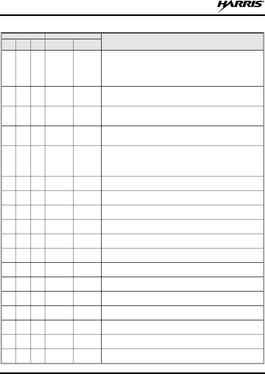
14221-1200-4000, Rev. E
24
Table 4-1: Maritime Frequencies
CHANNEL
FREQUENCY
CHANNEL USAGE
US
INTL
CA
SHIP
(MHz)
SHORE
(MHz)
73
73
73
T/R:
156.675
T/R:
156.675
US: Port Operations.
International: Intership, Port Operations.
Canada: May also be used for communications with aircraft engaged in
coordinated search and rescue and antipollution operations. Commercial
fishing only in east coast and inland Manitoba, Saskatchewan, and Alberta
areas.
74
74
74
T/R:
156.725
T/R:
156.725
US: Port Operations.
International: Port Operations.
Canada: VTS and Ship Movement British Columbia coast area.
75
75
T/R:
156.775
T/R:
156.775
International: Port Operations.
Canada: Simplex port operation, ship movement and navigation related
communication only. 1 watt maximum.
76
76
T/R:
156.825
T/R:
156.825
International: Port Operations.
Canada: Simplex port operation, ship movement and navigation related
communication only. 1 watt maximum.
77
77
77
T/R:
156.875
T/R:
156.875
US: Port Operations (Intership only).
International: Intership.
Canada: Pilotage - British Columbia coast area; 25 watts. Port operations
only in the St. Lawrence River/Great Lakes areas with 1 watt maximum
power.
78
T: 156.925
R: 161.525
T: 161.525
R: 156.925
International: Public Correspondence, Port Operations.
78a
78a
T/R:
156.925
T/R:
156.925
US: Non-Commercial.
Canada: Fishing Industry - British Columbia coast area.
79
T: 156.975
R: 161.575
T: 161.575
R: 156.975
International: Public Correspondence, Port Operations.
79a
79a
T/R:
156.975
T/R:
156.975
US: Commercial. Non-Commercial in Great Lakes only.
Canada: Fishing Industry - British Columbia coast area.
80
T: 157.025
R: 161.625
T: 161.625
R: 157.025
International: Public Correspondence, Port Operations.
80a
80a
T/R:
157.025
T/R:
157.025
US: Commercial. Non-Commercial in Great Lakes only.
Canada: Fishing Industry - British Columbia coast area.
81
T: 157.075
R: 161.675
T: 161.675
R: 157.075
International: Public Correspondence, Port Operations.
81a
81a
T/R:
157.075
T/R:
157.075
US: US Government only - Environmental protection operations.
Canada: DFO/Canadian Coast Guard use only.
82
T: 157.125
R: 161.725
T: 161.725
R: 157.125
International: Public Correspondence, Port Operations.
82a
82a
T/R:
157.125
T/R:
157.125
US: US. Government only.
Canada: DFO/Canadian Coast Guard use only.
83
T: 157.175
R: 161.775
T: 161.775
R: 157.175
International: Public Correspondence, Port Operations.
83a
83a
T/R:
157.175
T/R:
157.175
US: US Coast Guard only.
Canada: DFO/Canadian Coast Guard and other Government agencies.
83b
- -
T/R:
161.775
Canada: Continuous Marine Broadcast (CMB) service (weather).
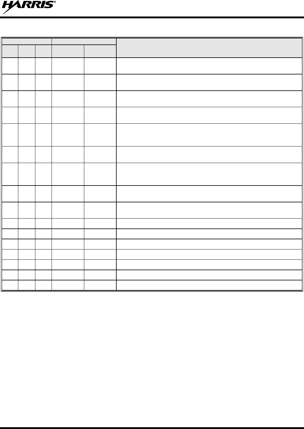
14221-1200-4000, Rev. E
25
Table 4-1: Maritime Frequencies
CHANNEL
FREQUENCY
CHANNEL USAGE
US
INTL
CA
SHIP
(MHz)
SHORE
(MHz)
84
84
84
T: 157.225
R: 161.825
T: 161.825
R: 157.225
US: Public Correspondence (Marine Operator).
International: Public Correspondence, Port Operations.
85
85
85
T: 157.275
R: 161.875
T: 161.875
R: 157.275
US: Public Correspondence (Marine Operator).
International: Public Correspondence, Port Operations.
86
86
86
T: 157.325
R: 161.925
T: 161.925
R: 157.325
US: Public Correspondence (Marine Operator).
International: Public Correspondence, Port Operations.
87
T/R:
157.375
T/R:
157.375
US: Public Correspondence (Marine Operator).
87
87
T: 157.375
R: 161.975
T: 161.975
R: 157.375
International: Port Operations.
Canada: Port operation and ship movement - east coast area.
Pleasure craft - British Columbia coast area.
AIS1
87b
T/R:
161.975
T/R:
161.975
US: Automatic Identification System.
Canada: Automatic Ship Identification and Surveillance System.
88
88
T: 157.425
R: 162.025
T: 162.025
R: 157.425
US: Commercial, Intership only.
International: Port Operations.
Canada: Port operation and ship movement - British Columbia coast area.
88a
T/R:
157.425
T/R:
157.425
US: Commercial, Intership only.
Canada: Automatic Ship Identification and Surveillance System.
88b
T/R:
162.025
T/R:
162.025
Automatic Identification System.
WX1
WX1
R: 162.55
Weather Channel 1 (receive only).
WX2
WX2
R: 162.4
Weather Channel 2 (receive only).
WX3
WX3
R: 162.475
Weather Channel 3 (receive only).
WX4
R: 162.425
Weather Channel 4 (receive only).
WX5
R: 162.45
Weather Channel 5 (receive only).
WX6
R: 162.5
Weather Channel 6 (receive only).
WX7
R: 162.525
Weather Channel 7 (receive only).
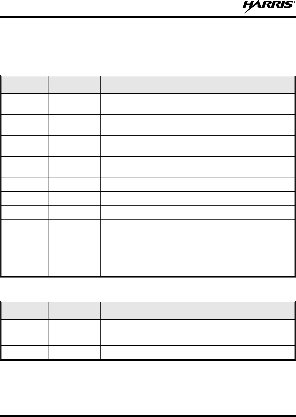
14221-1200-4000, Rev. E
26
5 CATALOG AND PART NUMBERS
Table 5-1 below lists applicable radio, control head, and held-held controller catalog and part numbers.
Refer to the Installation Manual for additional information:
Table 5-1: Unity XG-100M Mobile Radio/CH-100/CH-721 Control Head/HHC-731 Controller
Catalog and Part Numbers
CATALOG
NUMBER
PART NUMBER
DESCRIPTION
XM-100F
12099-1000-01
XG-100M Mobile Radio, 136 to 870 MHz, less Control Head (for front or
remote-mount radio)
XM-100F-D01
12099-1000-01
XG-100M Mobile Radio, 136 to 520 MHz, less Control Head (for front or
remote-mount radio)
XM-100F-D02
12099-1000-01
XG-100M Mobile Radio, 136 to 520 MHz and 762 to 870 MHz, less
Control Head (for front or remote-mount radio)
XM-100F-D03
12099-1000-01
XG-100M Mobile Radio, 380 to 870 MHz, less Control Head (for front or
remote-mount radio)
XMCP9R
12099-1200-01
CH-100 Control Head, Remote-Control (for remote-mount radio)
XMCP9Q
12099-1200-02
CH-100 Control Head, Local-Control (for front-mount radio)
XMCP9E
CU23218-0002
CH-721 Scan Control Head, Remote-Control (for remote-mount radio)
XMCP9F
CU23218-0004
CH-721 System Control Head, Remote-Control (for remote-mount radio)
XMCP9G
CU23218-0001
CH-721 Scan Control Head, Local-Control (for front-mount radio)
XMCP9H
CU23218-0003
CH-721 System Control Head, Remote-Control (for front-mount radio)
XMCP9P
CU-017821-001
HHC-731 Hand-Held Controller
Table 5-2: Unity XG-100M Mobile Radio with XG-100LPA Catalog and Part Numbers
CATALOG
NUMBER
PART NUMBER
DESCRIPTION
XM-100F or
XM-100F-D01 or
XM-100F-D02
12099-1000-01
Remote-Mount 35/50-Watt Multi-Band Unity XG-100M Mobile Radio
XM-100LPA
12099-3500-02
100W VHF Low Band Amplifier
14221-1200-4000, Rev. E
27
6 CUSTOMER SERVICE
6.1 CUSTOMER CARE
If any part of the system equipment is damaged on arrival, contact the shipper to conduct an inspection
and prepare a damage report. Save the shipping container and all packing materials until the inspection
and the damage report are completed. In addition, contact the Customer Care center to make
arrangements for replacement equipment. Do not return any part of the shipment until you receive
detailed instructions from a Harris representative.
Contact the Customer Care center at http://www.pspc.harris.com/CustomerService or:
North America:
Phone Number: 1-800-368-3277
Fax Number: 1-321-409-4393
E-mail: PSPC_CustomerFocus@harris.com
International:
Phone Number: 1-434-455-6403
Fax Number: 1-321-409-4394
E-mail: PSPC_InternationalCustomerFocus@harris.com
6.2 TECHNICAL ASSISTANCE
The Harris Technical Assistance Center (TAC) resources are available to help you with overall system
operation, maintenance, upgrades, and product support. TAC is your point of contact when you need
technical questions answered.
Product specialists, with detailed knowledge of product operation, maintenance, and repair, provide
technical support via a toll-free telephone number (in North America). Support is also available through
mail, fax, and e-mail.
For more information about technical assistance services, contact your sales representative, or call the
Technical Assistance Center directly at:
North America: 1-800-528-7711
International: 1-434-385-2400
Fax: 1-434-455-6712
E-mail: PSPC_tac@harris.com
7 WARRANTY REGISTRATION
Please register this product within 10 days of purchase. Registration validates the warranty coverage, and
enables Harris to contact you in case of any safety notifications issued for this product.
Registration can be made on-line at the Customer Care center webpage:
http://www.pspc.harris.com/Service/Customerservice.aspx.
While on the webpage, please review the applicable battery and/or product warranty literature.

Public Safety and Professional Communications | www.pspc.harris.com
221 Jefferson Ridge Parkway | Lynchburg, VA USA 24501 | 1-800-528-7711