Harris RF Communications Division XG-100M00 Unity MultiBand Mobile User Manual Manual 2
Harris Corporation RF Communications Division Unity MultiBand Mobile Manual 2
Contents
Manual 2

Operator’s Manual
14221-1200-2010
May/11
UNITY® XG-100M Mobile Radio
With CH-100 Control Head
Full-Spectrum Multiband Radio

10515-0372-4200, Rev. B
2
MANUAL REVISION HISTORY
REV. DATE REASON FOR CHANGE
- May/11 Initial release.
Harris Corporation, Public Safety and Professional Communications (PSPC) Business continually evaluates its technical publications for
completeness, technical accuracy, and organization. You can assist in this process by submitting your comments and suggestions to the
following:
Harris Corporation fax your comments to: 1-434-455-6851
PSPC Business or
Technical Publications e-mail us at: PSPC_TechPubs@harris.com
221 Jefferson Ridge Parkway
Lynchburg, VA 24501 ACKNOWLEDGEMENT
This product was developed using GEOTRANS, a product of the National Geospatial Intelligence Agency and U.S. Army Engineering
Research and Development Center. Use of this software does not indicate endorsement or approval of the product by the Secretary of
Defense or the National Geospatial Intelligence Agency.
This device made under license under one or more of the following US patents: 4,590,473; 4,636,791; 5,148,482; 5,185,796; 5,271,017;
5,377,229; 4,716,407; 4,972,460; 5,502,767; 5,146,697; 5,164,986; 5,185,795.
The Advanced Multi-Band Excitation implementation 2 (AMBE+2) voice coding Technology embodied in this product is protected by
intellectual property rights including patent rights, copyrights and trade secrets of Digital Voice Systems, Inc. This voice coding
Technology is licensed solely for use within this Communications Equipment. The user of this Technology is explicitly prohibited from
attempting to extract, remove, decompile, reverse engineer, or disassemble the Object Code, or in any other way convert the Object Code
into a human-readable form. U.S. Patent Nos. #5,870,405, #5,826,222, #5,754,974, #5,701,390, #5,715,365, #5,649,050, #5,630,011,
#5,581,656, #5,517,511, #5,491,772, #5,247,579, #5,226,084 and #5,195,166.
CREDITS
Harris, assuredcommunications, VIDA, EDACS, NetworkFirst, and OpenSky are registered trademarks of Harris Corporation.
Bluetooth is a registered trademark of Bluetooth SIG, Inc.
All brand and product names are trademarks, registered trademarks, or service marks of their respective holders.
Motorola is a registered trademark of Motorola, Inc.
AMBE is a registered trademark and IMBE, AMBE+, and AMBE+2 are trademarks of Digital Voice Systems, Inc.
NOTICE!
The material contained herein is subject to U.S. export approval. No export or re-export is permitted without written approval from the U.S.
Government. Rated: EAR99; in accordance with U.S. Dept. of Commerce regulations 15CFR774, Export Administration Regulations.
Information and descriptions contained herein are the property of Harris Corporation. Such information and descriptions may not be copied
or reproduced by any means, or disseminated or distributed without the express prior written permission of Harris Corporation, PSPC
Business, 221 Jefferson Ridge Parkway, Lynchburg, VA 24501.
Repairs to this equipment should be made only by an authorized service technician or facility designated by the supplier. Any repairs,
alterations or substitutions of recommended parts made by the user to this equipment not approved by the manufacturer could void the
user's authority to operate the equipment in addition to the manufacturer's warranty.
This product conforms to the European Union WEEE Directive 2002/96/EC. Do not dispose of this product in a public
landfill. Take it to a recycling center at the end of its life.
This manual is published by Harris Corporation
without any warranty. Improvements and changes to this manual necessitated by typographical errors,
inaccuracies of current information, or improvements to programs and/or equipment, may be made by Harris Corporation
at any time and without notice.
Such changes will be incorporated into new editions of this manual. No part of this manual may be reproduced or transmitted i
n any form or by any means,
electronic or mechanical, including photocopying and recording, for any purpose, without the express written permission of Harris Corporation.
Copyright © 2011, Harris Corporation.

14221-1200-2010
3
TABLE OF CONTENTS
Section Page
1.
SAFETY SYMBOL CONVENTIONS.................................................................................................. 6
2. RF ENERGY EXPOSURE INFORMATION ..................................................................................... 7
2.1 RF ENERGY EXPOSURE AWARENESS, CONTROL INFORMATION, AND OPERATION
INSTRUCTIONS FOR FCC OCCUPATIONAL USE REQUIREMENTS ................................ 7
2.1.1 Federal Communications Commission Regulations ........................................................ 7
2.2 COMPLIANCE WITH RF EXPOSURE STANDARDS............................................................. 8
2.2.1 Mobile Antennas (Vehicle Installations) ......................................................................... 8
2.2.2 Approved Accessories ..................................................................................................... 9
2.2.3 Contact Information ......................................................................................................... 9
2.3 REGULATORY APPROVALS ................................................................................................. 10
2.3.1 Part 15 ............................................................................................................................ 10
2.3.2 Industry Canada ............................................................................................................. 10
3. OPERATION SAFETY RECOMMENDATIONS ............................................................................ 11
3.1 TRANSMITTER HAZARDS..................................................................................................... 11
3.2 SAFE DRIVING RECOMMENDATIONS ............................................................................... 11
4. OPERATING RULES AND REGULATIONS .................................................................................. 12
5. INTRODUCTION ................................................................................................................................ 13
6. BASIC OPERATION ........................................................................................................................... 14
6.1 XG-100M CONTROLS .............................................................................................................. 14
6.2 DISPLAY ................................................................................................................................... 15
6.3 STATUS MESSAGES ............................................................................................................... 16
6.4 ALERT TONES.......................................................................................................................... 17
6.5 BEFORE FIRST USE ................................................................................................................. 18
6.6 POWER ON AND SET VOLUME ............................................................................................ 18
6.7 TURN ENCRYPTION ON OR OFF .......................................................................................... 18
6.8 USER INTERFACE PRIVILEGE LEVEL ................................................................................ 18
6.9 SELECT ZONE/SYSTEM USING MENUS ............................................................................. 19
6.10 USE TALKAROUND TO BYPASS REPEATER (CONVENTIONAL ONLY) ..................... 19
6.11 INDIVIDUAL CALLS ............................................................................................................... 21
6.11.1 Transmit an Individual Call ........................................................................................... 21
6.11.2 Receiving an Individual Call ......................................................................................... 21
6.12 SELECT A NEW TALKGROUP............................................................................................... 22
6.13 SCAN OPERATION .................................................................................................................. 23
6.13.1 Start Scan ....................................................................................................................... 23
6.13.2 Stop Scan ....................................................................................................................... 24
6.13.3 Nuisance Delete ............................................................................................................. 25
6.14 VIEW GPS INFORMATION ..................................................................................................... 25
6.15 EMERGENCY OPERATION .................................................................................................... 26
6.15.1 Declaring an Emergency Call ........................................................................................ 26
6.15.2 Receiving an Emergency Call ....................................................................................... 27
6.16 ENCRYPTION BAR .................................................................................................................. 27
6.17 LIGHTS AND SIRENS .............................................................................................................. 27
6.18 PUBLIC ADDRESS (PA) .......................................................................................................... 28
6.19 SHORTCUT MENU .................................................................................................................. 29
7. ADVANCED OPERATIONS .............................................................................................................. 30
7.1 CREATE KEYS ......................................................................................................................... 30
7.1.1 Create Keys using Harris Key Admin ........................................................................... 30
7.1.2
Create Key in the KVL 3000 Plus ................................................................................. 30

14221-1200-2010
4
7.1.3 Create Keygroup in the KVL 3000 Plus ........................................................................ 31
7.2 LOAD KEYS .............................................................................................................................. 31
7.2.2 Load Keys using Harris Key Loader ............................................................................. 32
7.2.3 Load Keys using Motorola KVL 3000 Plus .................................................................. 33
7.3 LOAD KEYGROUPS ................................................................................................................ 34
7.4 ZEROIZE ALL FROM RADIO ................................................................................................. 35
7.5 ZEROIZE KEYS USING KVL 3000 PLUS .............................................................................. 36
7.6 ZEROIZE KEYGROUPS USING KVL 3000 PLUS ................................................................. 36
7.7 ZEROIZE ALL FROM KVL 3000 PLUS .................................................................................. 37
7.8 GLOBAL ENCRYPTION .......................................................................................................... 37
7.9 SELECT KEYSET ..................................................................................................................... 39
7.10 OTAR CONFIGURATION ........................................................................................................ 39
7.11 ACTIVATE/VIEW MISSION PLAN ........................................................................................ 40
7.12 CH INFO MENU ........................................................................................................................ 41
7.13 SETTINGS MENU ..................................................................................................................... 41
7.13.1 Audio Settings ............................................................................................................... 42
7.13.2 Display Settings ............................................................................................................. 43
7.13.3 GPS Settings .................................................................................................................. 43
7.13.4 Bluetooth ....................................................................................................................... 44
7.13.5 Clock Settings ................................................................................................................ 46
7.13.6 Color Theme .................................................................................................................. 47
7.14 SET UP SCAN ........................................................................................................................... 47
7.14.1 Home, Priority 1, and Priority 2 Channels ..................................................................... 47
7.14.2 Zone Scan ...................................................................................................................... 48
7.14.3 Group Scan .................................................................................................................... 48
7.14.4 Vote Scan ....................................................................................................................... 48
7.14.5 Set or Remove Priority 1 and Priority 2 Channels ......................................................... 49
7.14.6 Wide Area System Scan (P25 Trunked Only) ............................................................... 50
7.15 MESSAGE MENU ..................................................................................................................... 50
7.16 UTILITIES MENU ..................................................................................................................... 50
8. PROGRAMMING ................................................................................................................................ 52
8.1 PROGRAMMING VIA RPM .................................................................................................... 52
8.2 EDIT CHANNEL (CONVENTIONAL ONLY) ........................................................................ 52
9. REFERENCE ........................................................................................................................................ 54
9.1 MARINE FREQUENCIES......................................................................................................... 54
9.2 ACCESSORIES .......................................................................................................................... 60
10. GLOSSARY .......................................................................................................................................... 61
11. BASIC TROUBLESHOOTING .......................................................................................................... 64
11.1 ERROR MESSAGES ................................................................................................................. 64
11.2 OTAR ERRORS/INFORMATION ............................................................................................ 65
12. TECHNICAL ASSISTANCE .............................................................................................................. 67
13. WARRANTY ........................................................................................................................................ 68
FIGURES
Page
Figure 6-1: Main Displays ............................................................................................................................. 15
Figure 6-2: User Interface Privilege ............................................................................................................... 18

14221-1200-2010
5
TABLES
Page
Table 2-2: Recommended Minimum Safe Lateral Distance from a Transmitting Antenna Connected to a
Unity XG-100M Mobile Radio ...................................................................................................................... 8
Table 6-1: XG-100M Controls and Connectors ............................................................................................. 14
Table 6-2: Icons ............................................................................................................................................. 16
Table 6-3: Status Messages ............................................................................................................................ 16
Table 6-4: Alert Tones ................................................................................................................................... 17
Table 6-5: Encryption Bar Indications ........................................................................................................... 27
Table 8-1: Valid Frequencies ......................................................................................................................... 53
Table 9-1: Marine Frequencies ...................................................................................................................... 54
14221-1200-2010
6
1. SAFETY SYMBOL CONVENTIONS
The following conventions are used to alert the user to general safety precautions that must be observed
during all phases of operation, service, and repair of this product. Failure to comply with these
precautions or with specific warnings elsewhere violates safety standards of design, manufacture, and
intended use of the product. Harris Corporation assumes no liability for the customer's failure to comply
with these standards.
WARNING
The WARNING symbol calls attention to a procedure, practice, or the like,
which, if not correctly performed or adhered to, could result in personal injury.
Do not proceed beyond a WARNING symbol until the conditions identified are
fully understood or met.
CAUTION
The CAUTION symbol calls attention to an operating procedure, practice, or the like,
which, if not performed correctly or adhered to, could result in a risk of danger,
damage to the equipment, or severely degrade the equipment performance.
NOTE
The NOTE symbol calls attention to supplemental information, which may improve
system performance or clarify a process or procedure.
The ESD
symbol calls attention to procedures, practices, or the like, which could
expose equipment to the effects of Electro-Static Discharge. Proper precautions must
be taken to prevent ESD when handling circuit modules.
14221-1200-2010
7
2. RF ENERGY EXPOSURE INFORMATION
2.1 RF ENERGY EXPOSURE AWARENESS, CONTROL INFORMATION,
AND OPERATION INSTRUCTIONS FOR FCC OCCUPATIONAL USE
REQUIREMENTS
Before using your mobile two-way radio, read this important RF energy awareness and control
information and operational instructions to ensure compliance with the FCC’s RF exposure
guidelines.
NOTE
This radio is intended for use in occupational/controlled conditions, where users have full
knowledge of their exposure and can exercise control over their exposure to meet FCC
limits. This radio device is NOT authorized for general population, consumer, or any
other use.
CAUTION
Changes or modifications not expressly approved by Harris Corporation could void the
user's authority to operate the equipment.
This two-way radio uses electromagnetic energy in the radio frequency (RF) spectrum to provide
communications between two or more users over a distance. It uses RF energy or radio waves to send and
receive calls. RF energy is one form of electromagnetic energy. Other forms include, but are not limited
to, electric power, sunlight, and x-rays. RF energy, however, should not be confused with these other
forms of electromagnetic energy, which, when used improperly, can cause biological damage. Very high
levels of x-rays, for example, can damage tissues and genetic material.
Experts in science, engineering, medicine, health, and industry work with organizations to develop
standards for exposure to RF energy. These standards provide recommended levels of RF exposure for
both workers and the general public. These recommended RF exposure levels include substantial margins
of protection. All two-way radios marketed in North America are designed, manufactured, and tested to
ensure they meet government established RF exposure levels. In addition, manufacturers also recommend
specific operating instructions to users of two-way radios. These instructions are important because they
inform users about RF energy exposure and provide simple procedures on how to control it. Please refer
to the following websites for more information on what RF energy exposure is and how to control your
exposure to assure compliance with established RF exposure limits.
http://www.fcc.gov/oet/rfsafety/rf-faqs.html
http://www.osha.gov./SLTC/radiofrequencyradiation/index.html
2.1.1 Federal Communications Commission Regulations
Your Harris Corporation Unity mobile two-way radio is designed and tested to comply with the FCC RF
energy exposure limits for mobile two-way radios before it can be marketed in the United States. When
two-way radios are used as a consequence of employment, the FCC requires users to be fully aware of
and able to control their exposure to meet occupational requirements. Exposure awareness can be
facilitated by the use of a label directing users to specific user awareness information. Your Harris
Corporation Unity two-way radio has an RF exposure product label. Also, your Unity Installation and
Operator’s Manuals include information and operating instructions required to control your RF exposure
and to satisfy compliance requirements.
14221-1200-2010
8
2.2 COMPLIANCE WITH RF EXPOSURE STANDARDS
Your Harris Corporation Unity mobile two-way radio is designed and tested to comply with a number of
national and international standards and guidelines (listed below) regarding human exposure to RF
electromagnetic energy. This radio complies with the IEEE and ICNIRP exposure limits for
occupational/controlled RF exposure environment at duty factors of up to 50% talk-50% listen and is
authorized by the FCC for occupational use. In terms of measuring RF energy for compliance with the
FCC exposure guidelines, your radio antenna radiates measurable RF energy only while it is transmitting
(talking), not when it is receiving (listening) or in standby mode.
Your Harris Corporation Unity mobile two-way radio complies with the following RF energy exposure
standards and guidelines:
• United States Federal Communications Commission (FCC), Code of Federal Regulations; 47 CFR §§
2 sub-part J.
• American National Standards Institute (ANSI)/Institute of Electrical and Electronic Engineers (IEEE)
C95.1-2005.
• Institute of Electrical and Electronic Engineers (IEEE) C95.1-2005.
• IC standard RSS-102, Issue 2, 2005: “Spectrum Management and Telecommunications Radio
Standards Specification. Radiofrequency Exposure Compliance of Radiocommunication Apparatus
(All Frequency Bands).
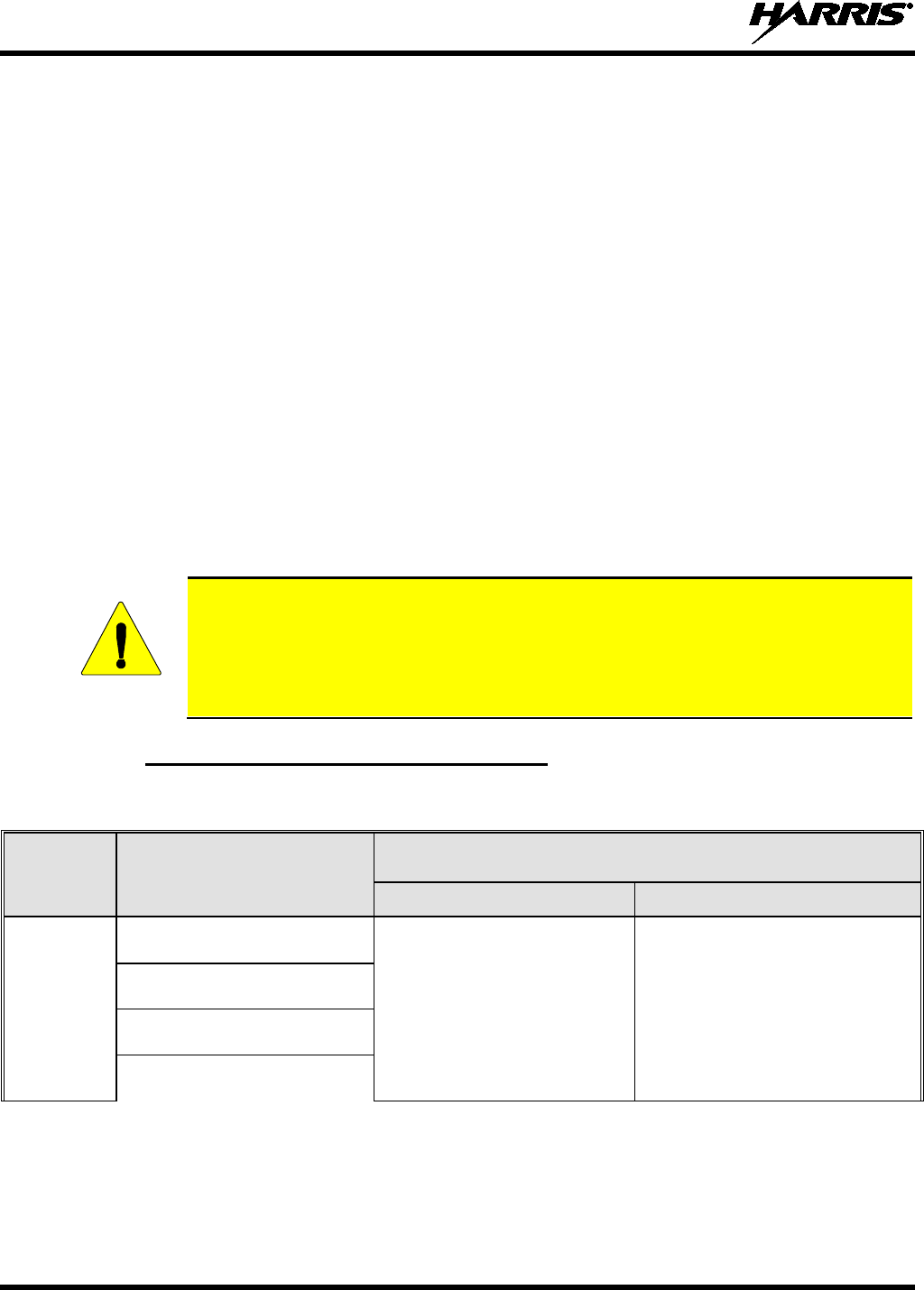
CAUTION
Error! Reference source not found. lists the recommended minimum lateral distance
for a controlled environment and for unaware bystanders in an uncontrolled
environment, from transmitting types of antennas (i.e., monopoles over a ground plane,
or dipoles) at rated radio power for mobile radios installed in a vehicle. Transmit only
when unaware bystanders are at least the uncontrolled recommended minimum lateral
distance away from the transmitting antenna.
2.2.1 Mobile Antennas (Vehicle Installations)
Table 2-1: Recommended Minimum Safe Lateral Distance from a
Transmitting Antenna Connected to a Unity XG-100M Mobile Radio
RF BAND ANTENNA
PART NUMBERS
RECOMMENDED MINIMUM LATERAL HUMAN BODY DISTANCE
FROM TRANSMITTING ANTENNA
CONTROLLED ENVIRONMENT UNCONTROLLED ENVIRONMENT
VHF
AN-125001-002 (mount) with
12099-0310-01 (element)
28.3 inches
(72 centimeters) 63.0 inches
(160 centimeters)
AN-125001-004 (mount) with
12099-0310-01 (element)
AN-125001-006 (mount) with
12099-0310-01 (element)
AN-125001-008 (mount) with
12099-0310-01 (element)
14221-1200-2010
9
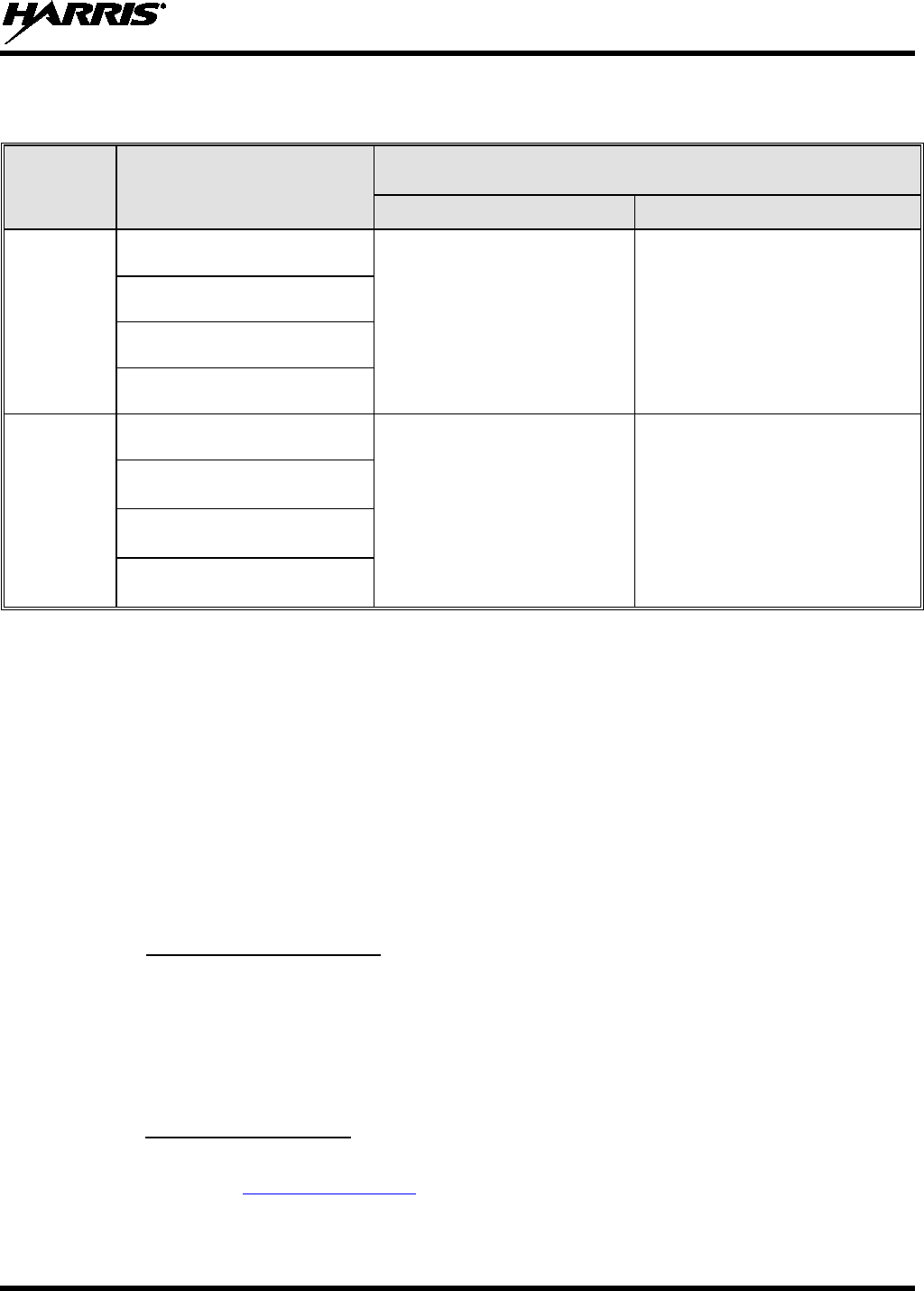
Table 2-1: Recommended Minimum Safe Lateral Distance from a
Transmitting Antenna Connected to a Unity XG-100M Mobile Radio
RF BAND ANTENNA
PART NUMBERS
RECOMMENDED MINIMUM LATERAL HUMAN BODY DISTANCE
FROM TRANSMITTING ANTENNA
CONTROLLED ENVIRONMENT UNCONTROLLED ENVIRONMENT
UHF
AN-125001-002 (mount) with
12099-0310-01 (element)
24.4 inches
(62 centimeters) 54.3 inches
(138 centimeters)
AN-125001-004 (mount) with
12099-0310-01 (element)
AN-125001-006 (mount) with
12099-0310-01 (element)
AN-125001-008 (mount) with
12099-0310-01 (element)
700/800 MHz
AN-125001-002 (mount) with
12099-0310-01 (element)
7.9 inches
(20 centimeters) 19.7 inches
(50 centimeters)
AN-125001-004 (mount) with
12099-0310-01 (element)
AN-125001-006 (mount) with
12099-0310-01 (element)
AN-125001-008 (mount) with
12099-0310-01 (element)
* Install the radio’s antenna (refer to Error! Reference source not found. for applicable antenna part numbers)
in the center of the vehicle’s roof. These mobile antenna installation guidelines are limited to metal body
motor vehicles or vehicles with appropriate ground planes. The antenna installation should additionally be
in accordance with the following:
• The requirements of the antenna manufacturer/supplier included with the antenna.
• Instructions in the Unity Radio Installation Manual, including minimum antenna cable lengths.
• The installation manual providing specific information of how to install the antennas to facilitate
recommended operating distances to all potentially exposed persons.
Use only the Harris Corporation approved/supplied antenna(s) or approved replacement antenna.
Unauthorized antennas, modifications, or attachments could damage the radio and may violate FCC
regulations.
2.2.2 Approved Accessories
This radio has been tested and meets the FCC RF guidelines when used with the Harris Corporation
accessories supplied or designated for use with this product. Use of other accessories may not ensure
compliance with the FCC’s RF exposure guidelines, and may violate FCC regulations.
For a list of approved accessories refer to the product manuals, the Products and Services Catalog, or
contact Harris Corporation at 1-800-368-3277.
2.2.3 Contact Information
For additional information on exposure requirements or other information, contact Harris Corporation at
1-800-528-7711 or at www.pspc.harris.com.

14221-1200-2010
10
2.3 REGULATORY APPROVALS
2.3.1 Part 15
This device complies with Part 15 of the FCC Rules. Operation is subject to the following two conditions:
1. This device may not cause harmful interference, and
2. This device must accept any interference received, including interference that may cause undesired
operation.
2.3.2 Industry
Le présent appareil est conforme aux CNR d'Industrie Canada applicables aux appareils radio exempts de
licence. L'exploitation est autorisée aux deux conditions suivantes : (1) l'appareil ne doit pas produire de
brouillage, et (2) l'utilisateur de l'appareil doit accepter tout brouillage radioélectrique subi, même si le
brouillage est susceptible d'en compromettre le fonctionnement.
Canada

14221-1200-2010
11
3. OPERATION SAFETY RECOMMENDATIONS
3.1 TRANSMITTER HAZARDS
WARNING
The operator of any mobile radio should be aware of certain hazards common to
the operation of vehicular radio transmitters. A list of several possible hazards is
given:
• Explosive Atmospheres – Just as it is dangerous to fuel a vehicle with the motor running, similar
hazards exist when operating a mobile radio. Be sure to turn the radio off while fueling a vehicle. Do
not carry containers of fuel in the trunk of a vehicle if the radio is mounted in the trunk.
Areas with potentially explosive atmosphere are often, but not always, clearly marked. Turn OFF
your radio when in any area with a potentially explosive atmosphere. It is rare, but not impossible that
the radio or its accessories could generate sparks.
• Interference to Vehicular Electronics Systems – Electronic fuel injection systems, electronic anti-
skid braking systems, electronic cruise control systems, etc., are typical electronic systems that can
malfunction due to the lack of protection from radio frequency energy present when transmitting. If
the vehicle contains such equipment, consult the dealer and enlist their aid in determining the
expected performance of electronic circuits when the radio is transmitting.
• Electric Blasting Caps – To prevent accidental detonation of electric blasting caps, DO NOT use
two-way radios within 1000 feet of blasting operations. Always obey the “Turn off Two-Way
Radios” signs posted where electric blasting caps are being used. (OSHA Standard: 1926-900)
• Liquefied Petroleum (LP) Gas Powered Vehicles – Mobile radio installations in vehicles powered
by liquefied petroleum gas with the LP gas container in the trunk or other sealed-off space within the
interior of the vehicle must conform to the National Fire Protection Association standard NFPA 58
requiring:
The LP gas container and its fittings.
Outside filling connections shall be used for the LP gas container.
The LP gas container shall be vented to the outside of the vehicle.
3.2 SAFE DRIVING RECOMMENDATIONS
(Recommended by AAA)
• Read the literature on the safe operation of the radio.
• Keep both hands on the steering wheel and the microphone in its hanger whenever the vehicle is in
motion.
• Place calls only when the vehicle is stopped.
• When talking from a moving vehicle is unavoidable, drive in the slower lane. Keep conversations
brief.
• If a conversation requires taking notes or complex thought, stop the vehicle in a safe place and
continue the call.
• Whenever using a mobile radio, exercise caution.
14221-1200-2010
12
4. OPERATING RULES AND REGULATIONS
Two-way FM radio systems must be operated in accordance with the rules and regulations of the local,
regional, or national government.
In the United States, the Unity mobile radio must be operated in accordance with the rules and regulations
of the Federal Communications Commission (FCC). As an operator of two-way radio equipment, you
must be thoroughly familiar with the rules that apply to your particular type of radio operation. Following
these rules helps eliminate confusion, assures the most efficient use of the existing radio channels, and
results in a smoothly functioning radio network.
When using your two-way radio, remember these rules:
• It is a violation of FCC rules to interrupt any distress or emergency message. As your radio operates
in much the same way as a telephone “party line,” always listen to make sure that the channel is clear
before transmitting. Emergency calls have priority over all other messages. If someone is sending an
emergency message – such as reporting a fire or asking for help in an accident – KEEP OFF THE
AIR!
• The use of profane or obscene language is prohibited by Federal law.
• It is against the law to send false call letters or false distress or emergency messages. The FCC
requires that you keep conversations brief and confine them to business. To save time, use coded
messages whenever possible.
• Using your radio to send personal messages (except in an emergency) is a violation of FCC rules.
You may send only those messages that are essential for the operation of your business.
• It is against Federal law to repeat or otherwise make known anything you overhear on your radio.
Conversations between others sharing your channel must be regarded as confidential.
• The FCC requires that you identify yourself at certain specific times by means of your call letters.
Refer to the rules that apply to your particular type of operation for the proper procedure.
• No changes or adjustments shall be made to the equipment except by an authorized or certified
electronics technician.
NOTE
Under
U.S. law, operation of an unlicensed radio transmitter within the jurisdiction of
the United States may be punishable by a fine of up to $10,000, imprisonment for up to
two (2) years, or both.
The following conditions tend to reduce the effective range of two-way radios and should be avoided
whenever possible:
• Operating the radio in areas of low terrain, or while under power lines or bridges.
• Obstructions such as mountains and buildings.
• In areas where transmission or reception is poor, some improvement can be obtained by moving a few
yards in another direction or moving to a higher elevation.

14221-1200-2010
13
5. INTRODUCTION
Your XG-100M provides full-spectrum multiband coverage:
• 30 to 50 MHz, VHF Low (Transmit requires external power amplifier)
• 136 to 174 MHz, VHF High (5 – 50 W)
• 380 to 520 MHz, UHF-Low, UHF-High (5 – 50 W)
• 762 to 805 MHz, 700 MHz (2 – 30 W)
• 805 to 870 MHz, 800 MHz (2 – 35 W)
The XG-100M has the following capabilities:
• Project 25 (P25) Conventional
• P25 Trunking
• Analog FM
• Advanced Encryption Standard, 256-bit (AES-256)
• Digital Encryption Standard Output Feedback (DES-OFB) Encryption
• Digital Encryption Standard Cipher Feedback (DES-CFB) Encryption
• Global Positioning System (GPS)
• Bluetooth®
• Over The Air Rekey (OTAR)
• Preemptive Priority Scanning
• Global Common Key References (CKR)
• Feature Management (Using Radio Personality Manager [RPM] R6A or later)
For optional accessories, refer to Section 9.2. Additional accessories may have been added since
publication of this manual; contact Harris for more information.
14221-1200-2010
14
6. BASIC OPERATION
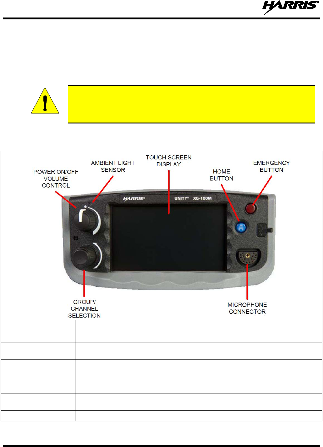
6.1 XG-100M CONTROLS
The XG-100M features a full color touch screen display for easy access to all radio features and
functions. To select an item, simply touch the desired area of the screen with your finger.
CAUTION
Never touch the screen with any metal or sharp objects, as this can damage the screen.
Table 6-1: XG-100M Controls and Connectors
POWER ON/OFF
VOLUME CONTROL
Turn knob clockwise to power on the radio and increase volume.
Turn counter-clockwise to decrease volume and power off the radio.
GROUP/CHANNEL
SELECTION
Selects the available groups or channels.
MICROPHONE
CONNECTOR
Connection for hand-held, hands-free, speaker-mic, or headset
AMBIENT LIGHT
SENSOR
The radio automatically adjusts the display and button backlight brightness level based on
ambient light. Do not block this sensor.
HOME BUTTON
Toggles through three available main screens or allows you to quickly navigate back to the main
screen from a submenu.
EMERGENCY BUTTON
Declares an emergency.
14221-1200-2010
15
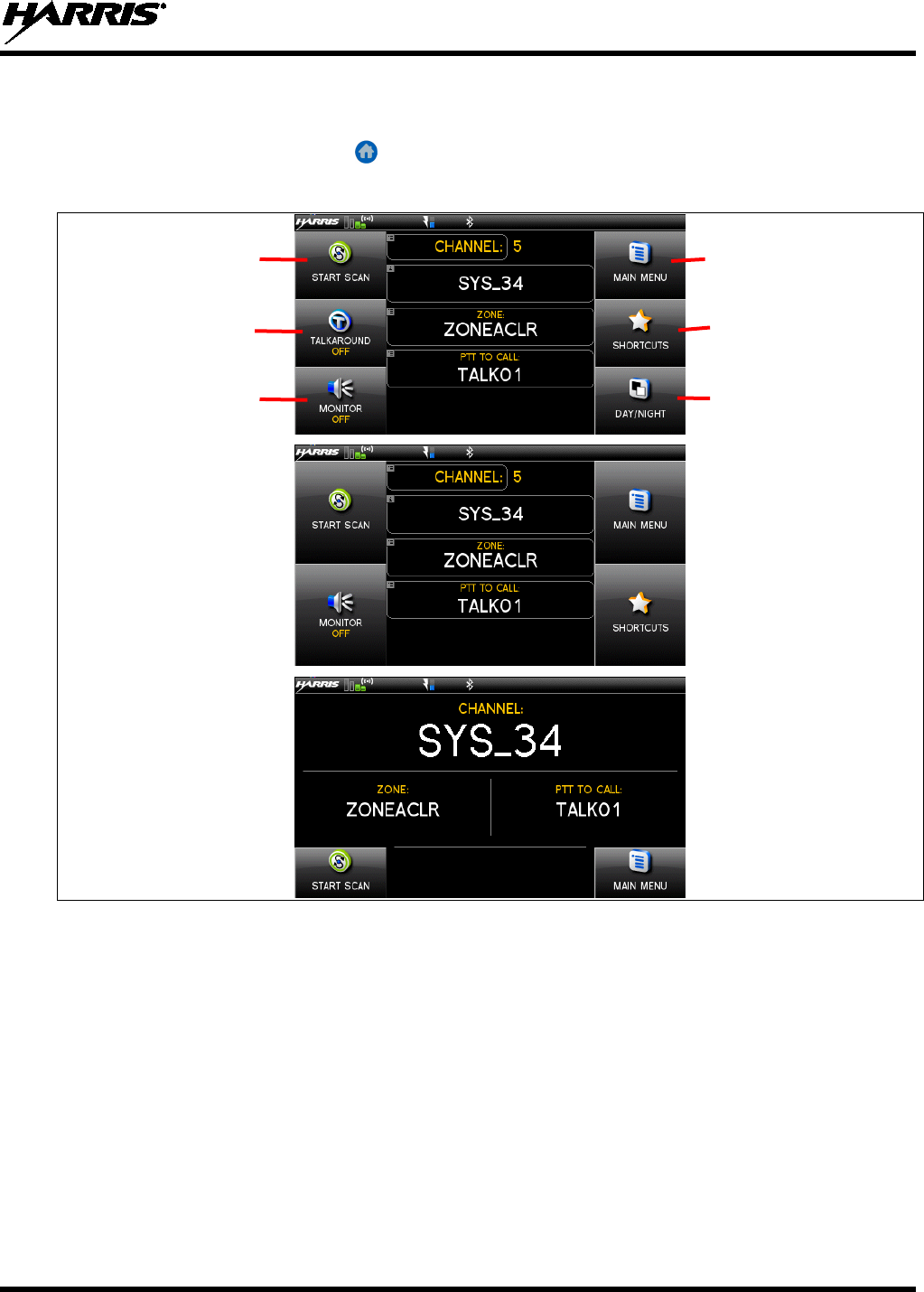
6.2 DISPLAY
One of three available main displays (Figure 6-1) appears after power up or after exiting from the menus.
While on the main screen, press the button to toggle through these displays.
To select an item, simply touch the desired area of the screen with your finger.
Figure 6-1: Main Displays
Accesses the
Main Menu
Accesses the
Shortcuts Menu
Toggles the display
between Day and
Night modes.
Toggles scan
on and off.
Toggles Talkaround
on and off.
Select the desired
monitor mode.
14221-1200-2010
16
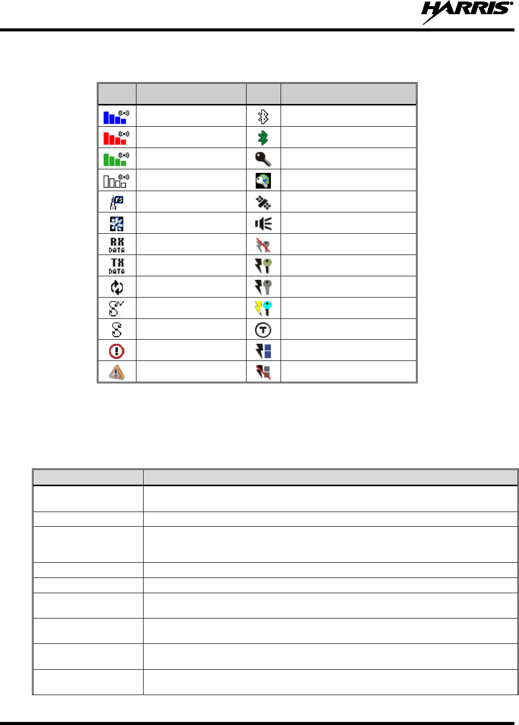
Table 6-2 describes the various icons that may be displayed at the top of the display.
Table 6-2: Icons
ICON
DESCRIPTION
ICON
DESCRIPTION
Trunked Signal Strength
Bluetooth Disabled
Transmitting
Bluetooth Enabled
Receiving
Encrypted Channel
Channel Idle
Global Encryption
Failsoft
GPS
Nuisance Delete
Monitor
Receiving Data
OTAR Disabled
Transmitting Data
OTAR Registered
Virtual Site
OTAR Registering
Volte Scanning
OTAR Rekeying
Scanning Enabled
Talkaround Enabled
Alert
Transmit Power
Emergency
RX Only
6.3 STATUS MESSAGES
During radio operation, various radio Status Messages may be displayed. The messages are described
below.
Table 6-3: Status Messages
MESSAGE DESCRIPTION
PTT DENIED P25 Trunked only -
Indicates the radio or talkgroup is not authorized to operate on the
selected system and/or talkgroup.
CALL QUEUED P25 Trunked only - Indicates the system has placed the call in a request queue.
SYSTEM BUSY P25 Trunked only - Indicates
the system is busy, no channels are currently available, the
queue is full, or an individual call is being attempted to a radio that is currently
transmitting.
SCANNING Indicates the radio is scanning.
TX EMERGENCY P25 modes only - Indicates an emergency call is being transmitted.
RX EMERGENCY P25 modes only - Indicates an emergency call is being received. If programmed via RPM,
the radio will display the unit name or unit ID.
WIDE AREA SCAN P25 Trunked only - Indicates the radio has entered the Wide Area Scan mode to search
for a new system (if enabled through programming).
INVALID TALKGROUP P25 Trunked only - Indicates the current talkgroup is not valid for the current system. This
could happen if the site denies registration due to an unrecognized talkgroup ID.
REGISTERING P25 Trunked only -
Displayed when the radio is performing a registration/affiliation on a
P25 trunking site.

14221-1200-2010
17
MESSAGE DESCRIPTION
CTRL CHANNEL SCAN P25 Trunked only - I
ndicates the control channel is lost and the radio has entered the
Contr
ol Channel Scan mode to search for the control channel (usually out of range
indication).
BAND SCANNING
P25 Trunked only - This message is o
nly displayed if the P25T system is configured for
"EnhancedCC" mode of operation. When the radio cannot find a Control Channel in either
the trunked frequency set or the list of discovered adjacencies, the radio is able to perform
a full spectrum frequency scan to find a new Control Channel.
6.4 ALERT TONES
Table 6-4 describes the alert tones that may be played by radio.
Table 6-4: Alert Tones
TONE DESCRIPTION SOUND/DURATION
Ready To Talk Tone
Unencrypted (Analog FM
or P25 digital)
After a PTT is pressed, this control enables the radio to
produce an audible indication (tone) for you to begin
speaking into the microphone. 1000 Hz for 25 ms
Ready to Talk Tone
Encrypted P25 digital
After a PTT is pressed, this control enables the radio to
produce an audible indication (tone) for you to begin
speaking into the microphone. 1200 Hz tone for 25 ms
PTT Denied
PTT not possible. Momentary tone is present:
• Receive only
• Key not found
• PTT button disabled
• Emergency button disabled
• Emergency not supported for current channel
• Clear transmit denied
544 Hz tone for 75 ms
Maximum transmit
duration expires Maximum transmit duration is exceeded. 5 beeps and then a 544 Hz
tone for 75 ms
Low Battery Alarm Alarm sounds upon initial detection of low battery and
every 30 seconds thereafter. Tone stops upon detection
of a battery charging state.
Sequence of tones:
• 937 Hz tone for 50 ms
• Silence for 60 ms
• 1300 Hz tone for 50 ms
Emergency Call
Received Radio is receiving an emergency call or priority call. 600 Hz tone for 250 ms and
1800 Hz tone for 250 ms
Out of Range Radio fails to find a local control channel.
Programmable via RPM:
• Disabled (no tone)
• Slow (tone every 15s)
• Medium (tone every 10s)
• Fast (tone every 5s)
14221-1200-2010
18
6.5 BEFORE FIRST USE
Make sure the XG-100M has:
• Mission plan and radio programmed using the RPM
• Encryption keys loaded if using encrypted channels
• Mission plan activated
6.6 POWER ON AND SET VOLUME
The power switch and volume control are within the same control. Turn clockwise to power on
XG-100M and to set to desired volume level.
6.7 TURN ENCRYPTION ON OR OFF
1. Select SHORTCUTS from the main display.
2. Select ENCRYPTION to toggle encryption on and off.
• A key appears on the display when encryption is enabled. The channel must also be programmed
to be encrypted.
• When encryption is turned on and you use any channel not configured for encryption, the radio
allows PTT. The signal is transmitted unencrypted.
• Channels configured for Global Encryption display a Global Encryption icon instead of key icon
(Section 7.8) if Global Encryption is enabled.
6.8 USER INTERFACE PRIVILEGE LEVEL
Depending on radio programming, some of the menu options described in this manual may not be
available. The following table details the menus available for the different levels of User Interface
Privilege:
Figure 6-2: User Interface Privilege
FULL
ACCESS
LIMITED
ACCESS
RESTRICTED
ACCESS
Audio Settings
GPS Settings
Clock Settings
Battery Setting
Bluetooth Settings
View/Edit Softkey (System List)
View/Edit (Zone List)
Zeroize
Keyset Changeover
Global Encryption
Global Key
Program Menu only in Active Mission Plan
Self-test on Utility Menu
14221-1200-2010
19
FULL
ACCESS
LIMITED
ACCESS
RESTRICTED
ACCESS
TCXO Tuning on Utility Menu
P25 Test Selection on Utility Menu
6.9 SELECT ZONE/SYSTEM USING MENUS
A zone/system is a group of channels that can be programmed by agency or geographical region. For
example, a zone/system could be for fire, police, New York, Los Angeles, etc.
1. At main display, select MAIN MENU.
2. Select ZONES.
3. Select the desired zone from the list.
If is selected, a screen appears allowing you to view the channels
in the zone/system.
A mission plan could have up to 512 zones/systems.
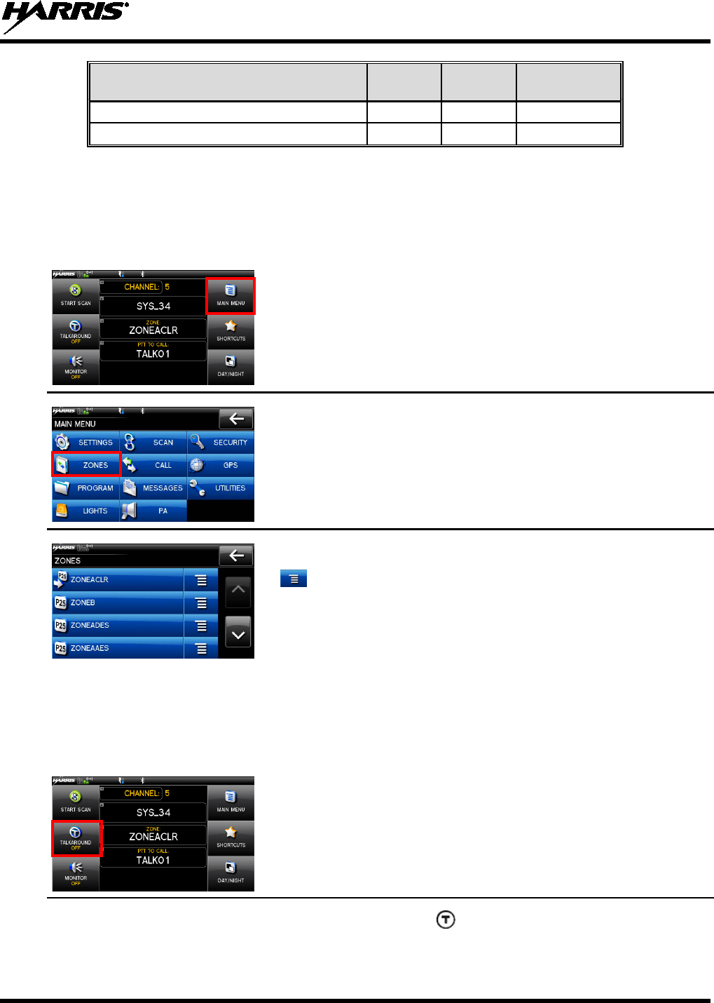
6.10 USE TALKAROUND TO BYPASS REPEATER (CONVENTIONAL ONLY)
You can bypass the repeater system to communicate directly with other radios on your current channel’s
receive frequency. This is useful if you are out of range of a repeater or if a repeater is busy. You will
need to be in range of the other radio.
1. At main display, select TALKAROUND to toggle talkaround on.
2. The Talkaround icon appears. Calls are
now made on the
receive frequency until you disable talkaround mode via the CALL
14221-1200-2010
20
menu. Power cycling the radio does not disable talkaround.
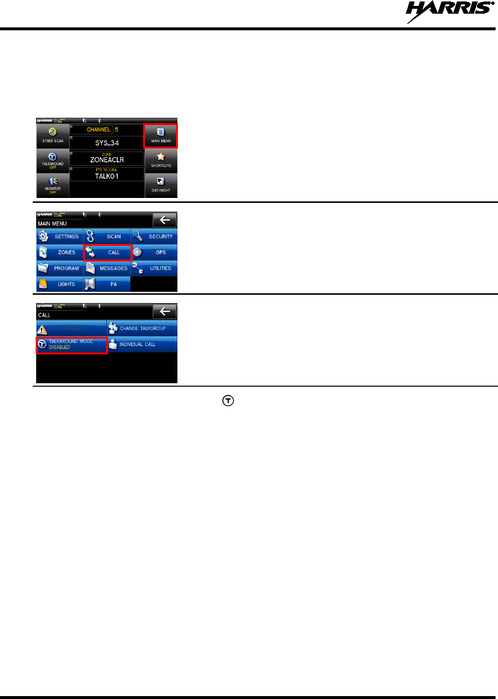
Or
1. At main display, select MAIN MENU.
2. Select CALL.
3. Select TALKAROUND MODE to toggle talkaround on.
4. The
icon appears. Calls are now made on the receive frequency
until you disable talkaround mode.
Power cycling the radio does
not disable talkaround.
14221-1200-2010
21
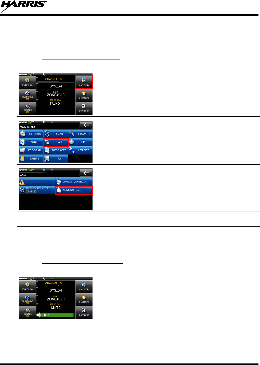
6.11 INDIVIDUAL CALLS
An individual call is used to make a call to one radio as opposed to a group of radios. An individual call
can only be made on a digital channel.
6.11.1 Transmit an Individual Call
1. At main display, select MAIN MENU.
2. Select CALL.
3. Select INDIVIDUAL CALL.
4. Select the unit to call.
5. Press PTT to make the call.
6. To end call, select END CALL.
6.11.2 Receiving an Individual Call
1. When receiving an Individual Call, the radio displays
the calling
radio’s name or Unit ID.
2. Press the PTT button to respond. The amount of time the radio will
remain in the Individual Call mode with no activity is
programmable via RPM.
14221-1200-2010
22
3. The radio rings and indicates a missed call if you do not respond to
an incoming Individual Call. The ring sounds
continuously until
you press PTT, select the missed call indication,
or power cycle
radio.
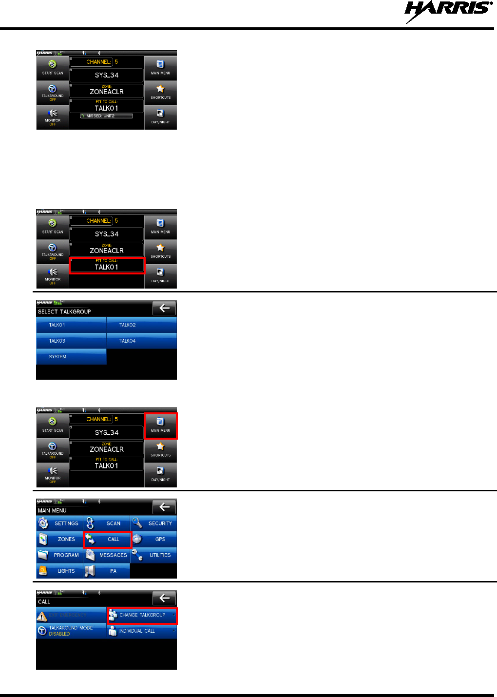
6.12 SELECT A NEW TALKGROUP
A talkgroup is a group of radios that you would want to have private conversations with. These groups
could be divided into areas such as state, region, county, or large special events. A talkgroup call can only
be made on digital channels. On the receiving radio, the calling station name appears in the activity area.
1. At main display, touch the currently displayed talkgroup.
2. Select the desired talkgroup. After selecting the new talkgroup, the
radio returns to the main display.
3. Press PTT to make the call.
OR
1. At main display, MAIN MENU.
2. Select CALL.
3. Select CHANGE TALKGROUP.
14221-1200-2010
23
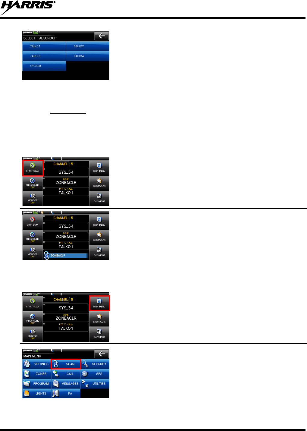
4. Select the talkgroup from the list.
After selecting the new
talkgroup, the radio returns to the main display.
5. Press PTT to make the call.
6.13 SCAN OPERATION
6.13.1 Start Scan
This procedure assumes that the scan list has been added and is not in active scan. Refer to Section 7.14
for scan setup or Section 6.13.2 for stopping scan. Refer to Section 7.14.1.1, Section 7.14.1.2, and Section
7.14.1.3 for home and priority channel descriptions.
1. At main display, select START SCAN.
2. The green START SCAN text changes to red STOP SCAN.
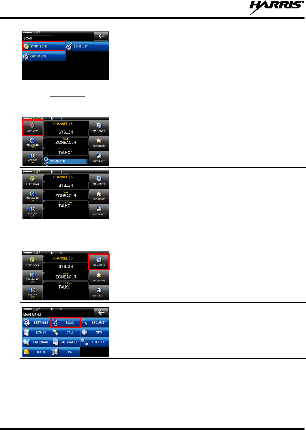
OR
1. At main display, select MAIN MENU.
2. Select SCAN.
14221-1200-2010
24
3. Select START SCAN. The green START SCAN text changes to
red STOP SCAN.
6.13.2 Stop Scan
Perform the following to stop an active scan.
1. At main display, select STOP SCAN.
2. The red STOP SCAN text changes to green START SCAN..
OR
1. At main display, select MAIN MENU.
2. Select SCAN.
3. Select STOP SCAN. The red STOP SCAN text changes to green
START SCAN.
14221-1200-2010
25
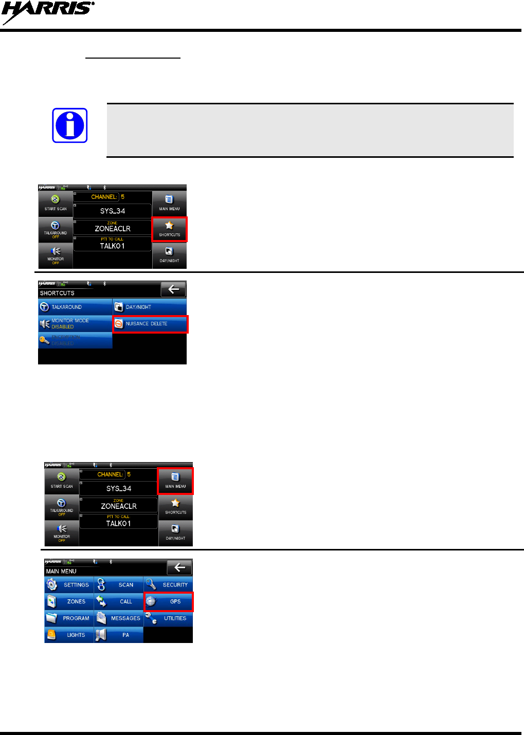
6.13.3 Nuisance Delete
A channel can temporarily be deleted from the scan list. Priority 1 and priority 2 channels cannot be
nuisance deleted.
NOTE
Nuisance delete can only be performed on the active scan list.
1. At main display, select SHORTCUTS.
2. Select NUISANCE DELETE.
6.14 VIEW GPS INFORMATION
You can use the internal Global Positioning System (GPS) receiver to view your position and satellite
information. Remember, GPS requires an unobstructed view of the sky and the signal is greatly
diminished inside buildings, tunnels, heavily forested areas, etc. GPS may not work at all under some
materials, especially metal.
1. At main display, select MAIN MENU.
2. Select GPS.
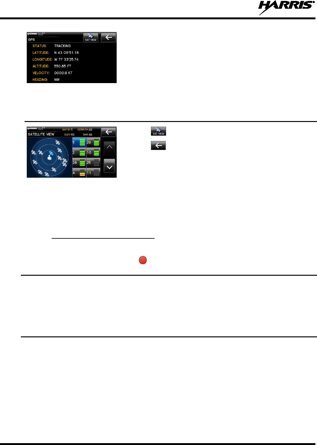
14221-1200-2010
26
You can observe GPS status:
• DISABLED - GPS is disabled via programming.
• TRACKING -
GPS has acquired satellite signal. GPS time
appears on top of display.
• SEARCHING -
GPS has not acquired. Harris logo appears on
top of display if GPS has not tracked after last power up of the
radio.
• LAST KNOWN POS -
Radio was tracking and then lost GPS
signal. The information displayed is from the last known position.
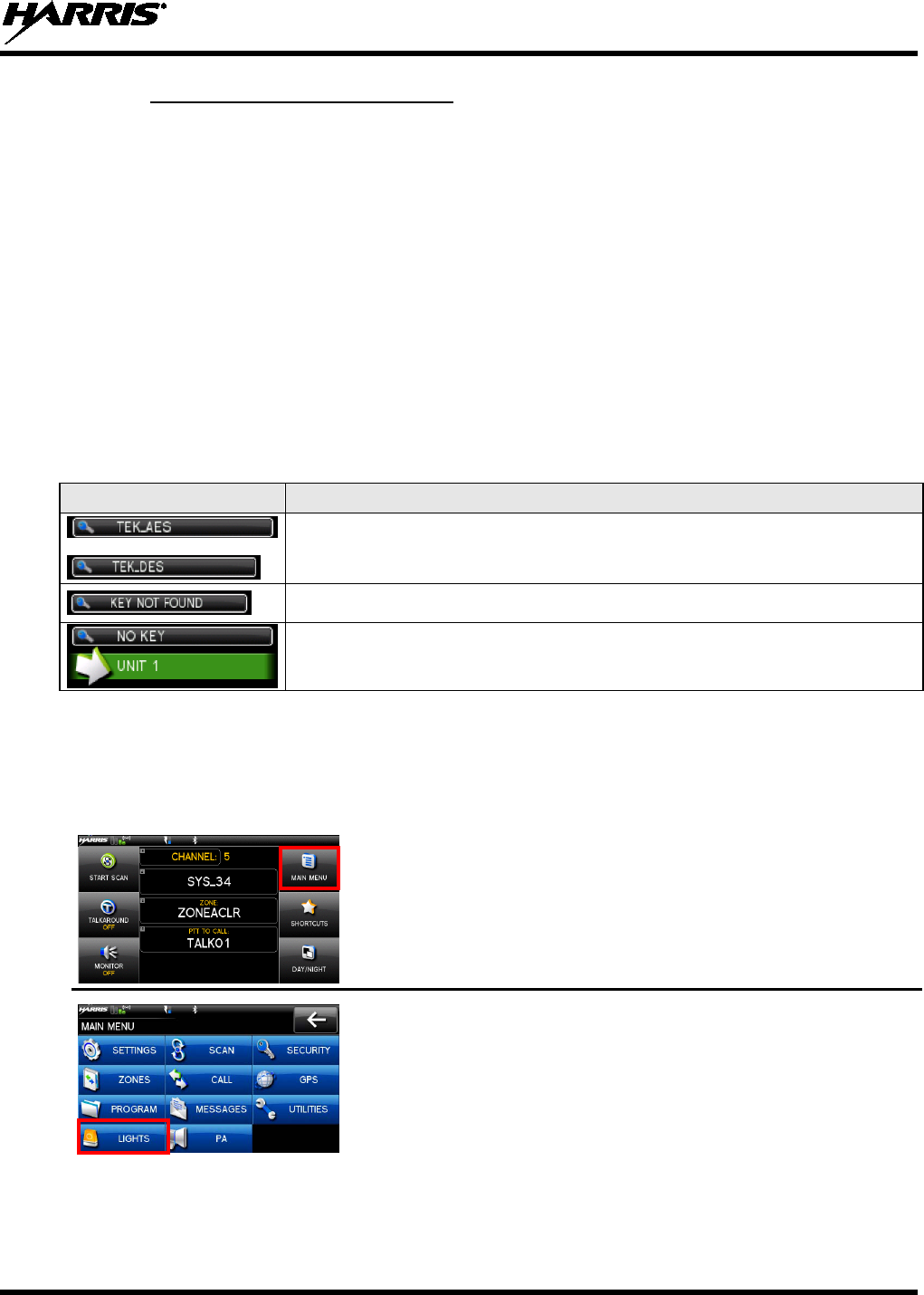
3. Select to view satellite information.
4. Select to exit GPS screens.
6.15 EMERGENCY OPERATION
The XG-100M can be programmed to enable emergency mode. Unit name displays on dispatcher console
if an emergency signal is received from another XG-100M on a digital channel.
6.15.1 Declaring an Emergency Call
1. Press and hold the button on the front of the control head. The length of time
you need to hold the button is configured in RPM.
For digital channels, the radio transmits the talkgroup or radio ID to the dispatch
console or receiving radio.
The radio will go through transmit and receive cycles if configured.
Speak into the microphone while the radio is transmitting or press PTT to talk.
2. To exit emergency, power cycle the radio or select EXIT EMERGENCY.
14221-1200-2010
27
6.15.2 Receiving an Emergency Call
When receiving an Emergency Call, an alert beep sounds (if tones are enabled) and an emergency
indication is displayed.
Depending on options selected in RPM, the unit ID or unit name may be displayed.
While the emergency display is active, press PTT to respond to the emergency caller.
6.16 ENCRYPTION BAR
The encryption bar is shown in Table 6-5. Encryption keys must be loaded (Section 7.2 or Section 7.3) for
these indications to be displayed.
Table 6-5: Encryption Bar Indications
DISPLAY DESCRIPTION
This is an example of a key name of an AES and a DES key being
transmitted or received.
Encryption key assigned to channel was not found.
This message appears on receive radios. Encryption key assigned to channel
was not used on transmitting radio.
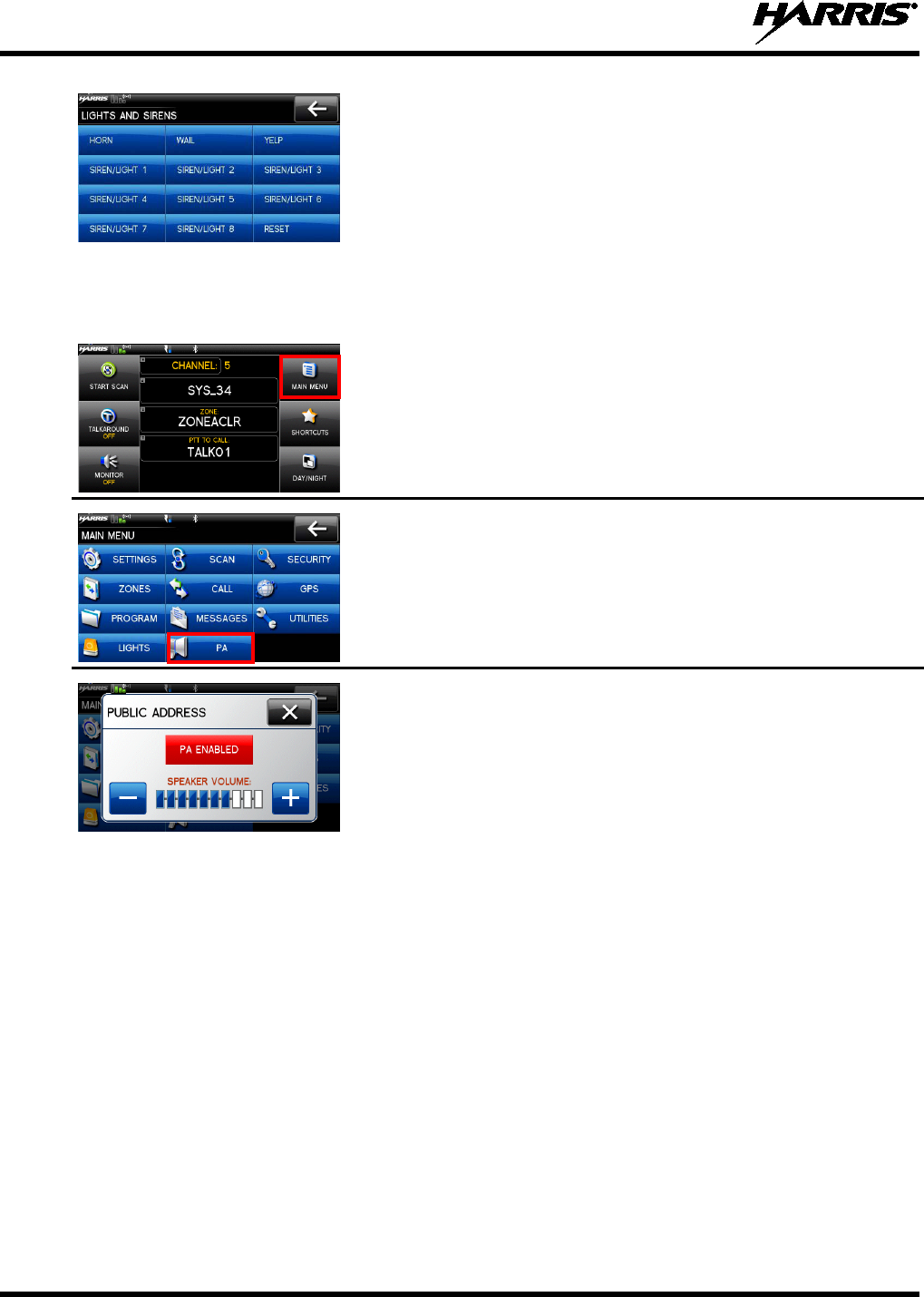
6.17 LIGHTS AND SIRENS
The lights and sirens feature allows you to activate the siren/light combination defined for the
corresponding button. The siren and light functions are programmable for any combination of siren and
lights.
1. At main display, select MAIN MENU.
2. Select LIGHTS.
14221-1200-2010
28
3. Select the desired option.
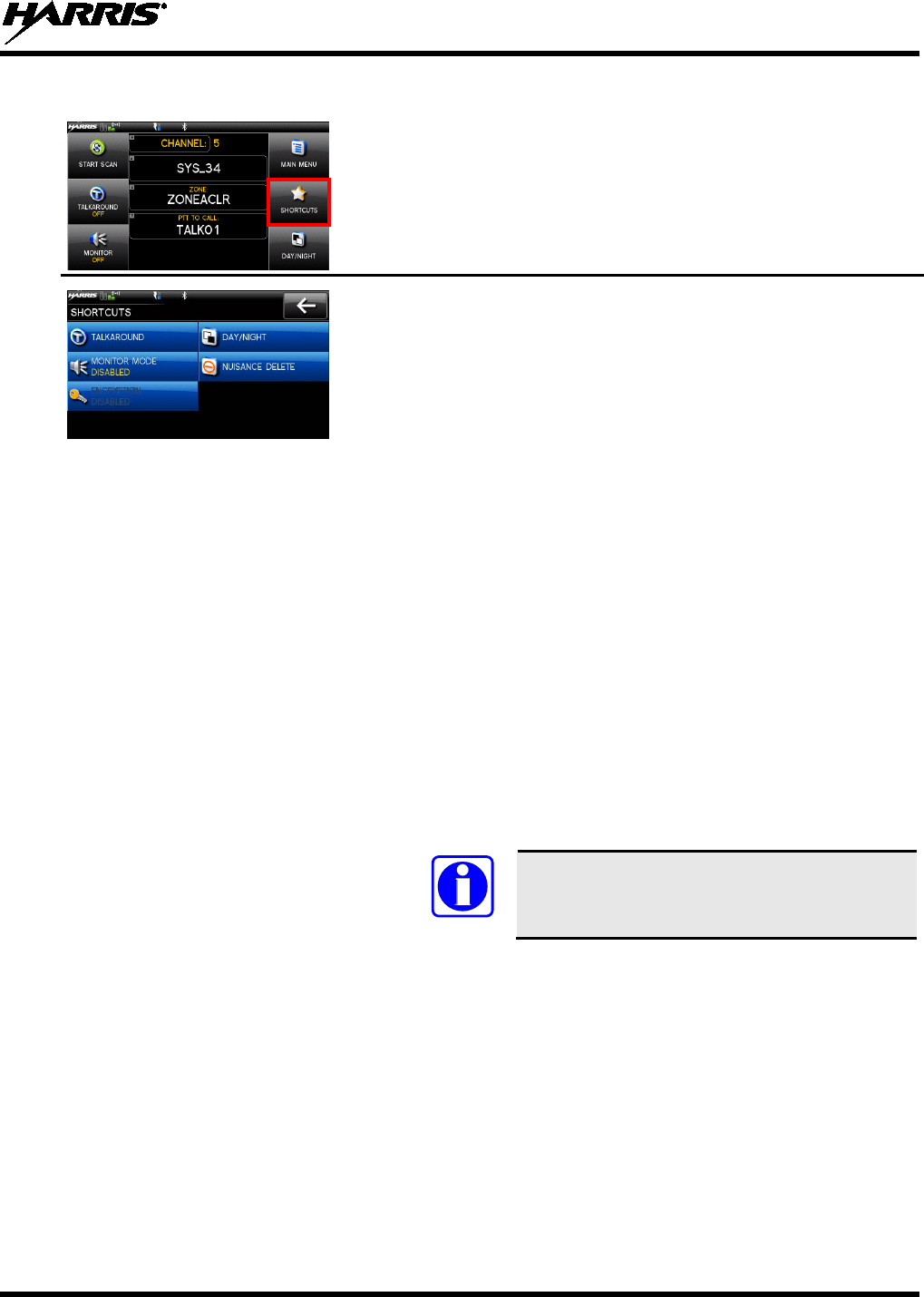
6.18 PUBLIC ADDRESS (PA)
To turn Public Address (PA) feature on/off and adjust the volume of the PA speaker:
1. At main display, select MAIN MENU.
2. Select PA.
3. Select PA ENABLED to disable PA or select PA DISABLED to
enable PA.
4. Use (+) or (-) to set the volume.
14221-1200-2010
29
6.19 SHORTCUT MENU
1. At main display, select SHORTCUTS.
2. Select the desired task:
• TALKAROUND –
(Conventional only) toggles talkaround on
and off.
• MONITOR MODE – (P25
Conventional and Analog
Conventional) Monitor and squelch types. This is grayed out if
radio is scanning.
For analog channels, there is:
Noise squelch - any received signal breaks squelch.
Continuous Tone Coded Squelch (CTCSS) -
squelch is
selective based on tone code.
Continuous Digital Coded Squelch (CDCSS) -
squelch is
selective based on digital code.
For digital channels, there is:
Monitor squelch -
any received digital signal breaks
squelch.
Normal squelch -
Received Network Access Code (NAC)
breaks squelch.
Selective squelch -
Received NAC and talkgroup
Identification (ID) or unit ID breaks squelch.
NOTE
During encrypted operations, the radio only
unmutes if receiving with the same key.
• NUISANCE DEL – Nuisance delete. This is grayed out if not
scanning or if the radio has declared an emergency.
• DAY/NIGHT –
Toggles the display between day and night
modes.
•
ENCYRPTION – Enables or disables encryption.
14221-1200-2010
30
7. ADVANCED OPERATIONS
7.1 CREATE KEYS
Refer to the following documentation for advanced programming and setup instructions:
• Motorola® KVL 3000 Plus Key Variable Loader (KVL) User's Guide
• Harris OTAR Overview Manual - MM-008069-001
• Network Key Manager Installation and Configuration Manual - MM-008070-001
• Harris UAS Key Management Application Manual - MM-008068-001
• Harris Key Manager Key Admin Overview and Operation Manual - MM1000019423
• Harris Key Manager Key Loader Overview and Operation Manual - MM1000019424
NOTE
If using Key Manager to create and load keys, ensure that you have version R5A or
later installed. Versions prior to R5A do not support the Unity radio.
7.1.1 Create Keys using Harris Key Admin
Harris Key Admin is part of the Harris Key Manager and is for use by the Crypto Officer (CO). The CO
creates a Master Set of keys from which a Distribution Set is produced. Using the Key Admin software,
the CO can save keys onto Distribution Security Devices to transport these keys to technicians for use in
radios.
1. Connect the Master Security Device to the PC.
2. Select Start Programs Harris Key Manager Harris Key Admin.
3. Select New Master Set or Load Existing Set. Refer to the Key Admin online help for more
information on creating keys.
4. When finished, create a Distribution Security Device. A Distribution Security Device is used with the
Key Loader to load key sets into the radio and cannot be edited. Refer to the Key Admin online help
for more information on creating the Distribution Security Device.
7.1.2 Create Key in the KVL 3000 Plus
You can generate a single Type-3 key in the KVL 3000 Plus key loading device:
1. Turn on the KVL 3000 Plus.
2. Select KEYS.
3. Select NEW.
4. Enter a number between 00001 and 04095 or between 61440 and 65535 at Common Key References
(CKR) prompt. The number must be unique on the KVL 3000 Plus.
5. Choose DES-OFB or AES-256 as the algorithm.
6. Select ACCEPT.
7. Enter Key Identification (KID) from 0001 to FFFF. The number must be different for each key of a
particular algorithm in the KVL 3000 Plus.
14221-1200-2010
31
NOTE
The XG-100 does not support KID 0000. Attempting to load a key with KID 0000
from the KVL will result in the failure
UNKNOWN ERRICHECK
TARGETALGORITHM! d
isplayed on the KVL. KID 0000 is reserved for the
Suppressed Key feature.
8. Enter a hexadecimal number as the Key value. DES-OFB keys are 16 digits while AES keys are 64
digits (32 bytes [256 bits]). Odd parity checks are made between every two digits for DES-OFB keys.
Parity checks are not made for AES-256 keys.
9. KVL 3000 Plus will display SLOT FILLED, press ENTER.
10. A message is displayed when complete: KEY WAS CREATED SUCCESSFULLY.
11. Refer to Section 7.2 for loading a key into the radio.
7.1.3 Create Keygroup in the KVL 3000 Plus
You can generate a group of Type-3 keys in the KVL 3000 Plus:
1. Turn on the KVL 3000 Plus.
2. Select Esc.
3. Select GROUPS.
4. Select NEW.
5. Enter a Group Name (up to seven characters).
6. Select CKRs from the programmed list until all desired CKRs are selected.
7. Select DONE. Refer to Section 7.2 for loading a keyset into the radio.
7.2 LOAD KEYS
7.2.1.1 Load UKEKs with UKEK Loader and RPM (for OTAR -E nabled S ys tems )
UKEKs are loaded into Harris OTAR radios using the UKEK Loader application. UKEK Loader is a part
of Key Manager.
To load encryption keys:
1. Obtain the UKEK file and Storage Location Number (SLN) Binding Report information from the
Crypto Officer (CO).
NOTE
Both AES and DES UKEKs can be contained within the same UKEK file
2. If not already on, power-up the PC that has RPM and the UKEK Loader applications installed on it,
and start Windows.
3. Connect the radio to the PC using programming cable 12082-0410-A1.
NOTE
The Unity drivers must be installed before UKEKs can be loaded into the radio. The Unity
drivers may be found on the Key Loader CD (“unity setup.exe”) or on the Key Admin CD
(“unity setup.exe”).

14221-1200-2010
32
4. Load the UKEK file from the Crypto Officer onto the PC.
5. Run the RPM application and setup the radio’s personality according the SLN Binding Report
information.
6. Setup the talk groups and the SLN mappings (Talk Group ID to SLN). This includes mapping SLNs
to the “System” keys (PSTN, All Call, etc.).
7. Select Options P25 OTAR Options and set the following:
a. The OTAR Message Number Period (MNP) as defined by the System Administrator.
b. The radio’s Individual RSI (from the SLN Bindings Report).
c. The KMF’s RSI (from the SLN Bindings Report).
8. Select Radio Program or click on the Program icon and write the personality to the radio.
9. Run the UKEK Loader application.
10. Open the UKEK file loaded in step 4.
11. Select the Target Device type (Auto-Detect is preferred) and click the Load button.
12. When prompted, enter your user name and password and click OK.
The UKEK Loader reads the target device’s identifying information, retrieves a UKEK of the proper
algorithm type from the UKEK file, and downloads the UKEK to the target device at the proper SLN
and keyset with the proper key ID.
13. Click the Finish button to exit the Key Loader application. New UKEKs have are loaded and the
radio is now ready to accept TEKs via OTAR with the trunked radio network.
7.2.2 Load Keys using Harris Key Loader
Harris Key Loader is part of Harris Key Manager and can be used by the Crypto Officer or Technician to
load the keys into the Unity radio.
Refer to the Harris Key Loader online help if additional information is required when performing this
procedure.
1. Connect the Distribution Security Device to the PC.
2. Connect the radio to the PC using the 12082-0410-A1 programming cable.
3. Power on the radio, if not already.
4. Select Start Programs Harris Key Manager Harris Key Loader.
5. At the Key Loader Welcome screen, click Next.
6. Enter the User Password for your Distribution Security Device and click Authenticate.
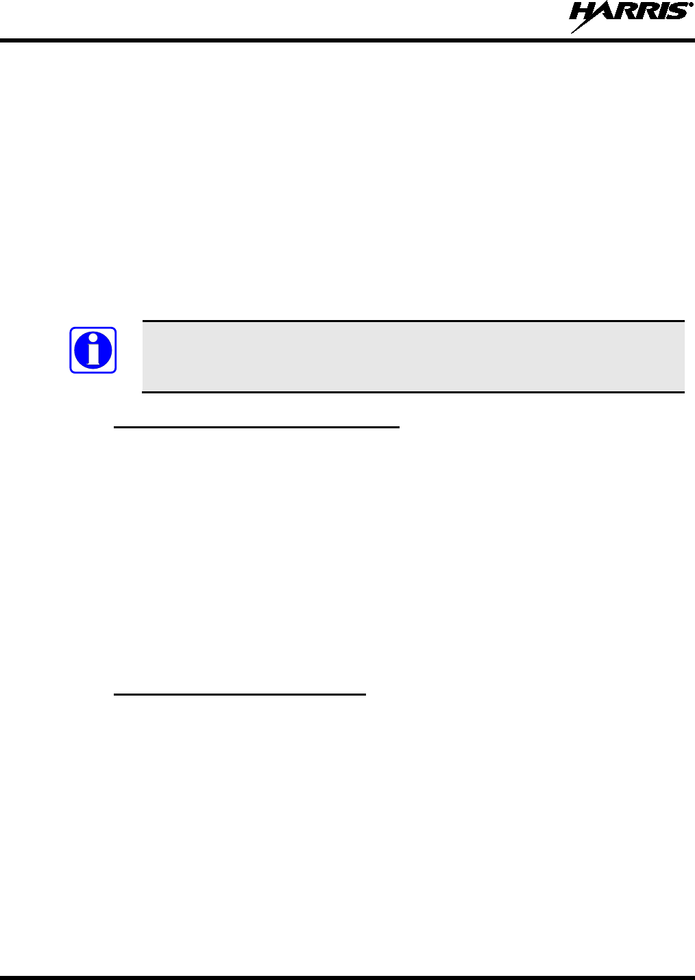
7. Click Next and click Next again.
8. Wait while the Key Loader reads the Distribution Set and click Next.
9. Select USB from the drop-down and click Next.
14221-1200-2010
33
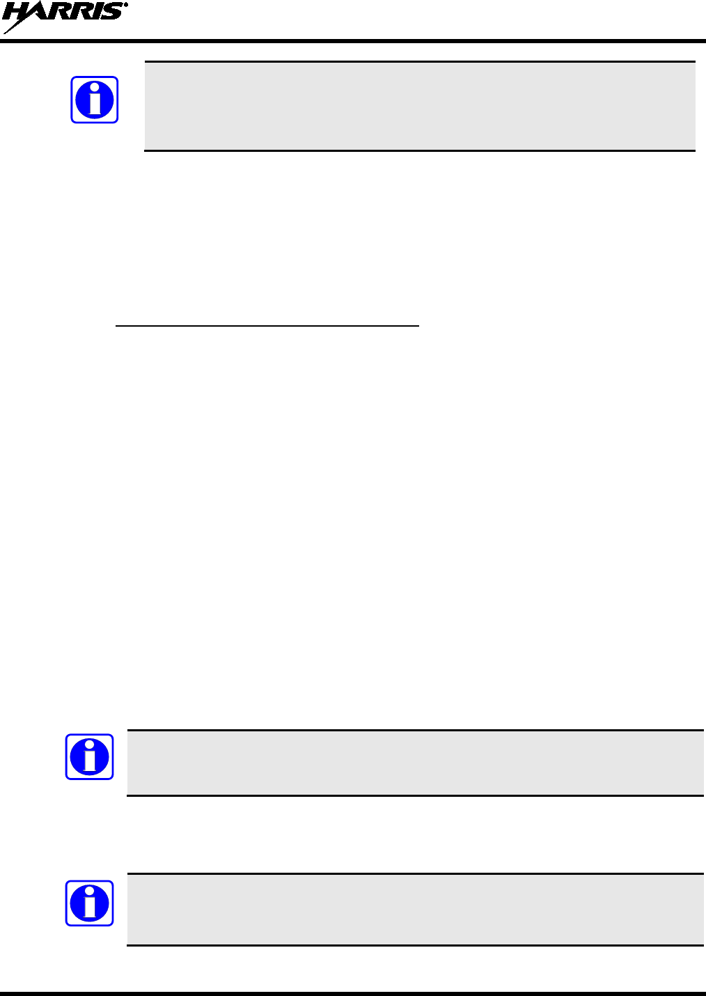
10. Select the Unity radio from the drop-down and click Load.
11. Click Finish.
7.2.3 Load Keys using Motorola KVL 3000 Plus
Type 3 Digital Encryption Standard Output Feedback (DES-OFB) and Advanced Encryption Standard,
256-bit (AES-256), encryption methods are supported. The Type 3 Encryption keys are loaded via a
Motorola KVL 3000 Plus device using Telecommunications Industry Association (TIA)/Project 25 (P25)
key fill device protocol. Make sure that valid keys have been created and stored in the KVL 3000 Plus
before proceeding.
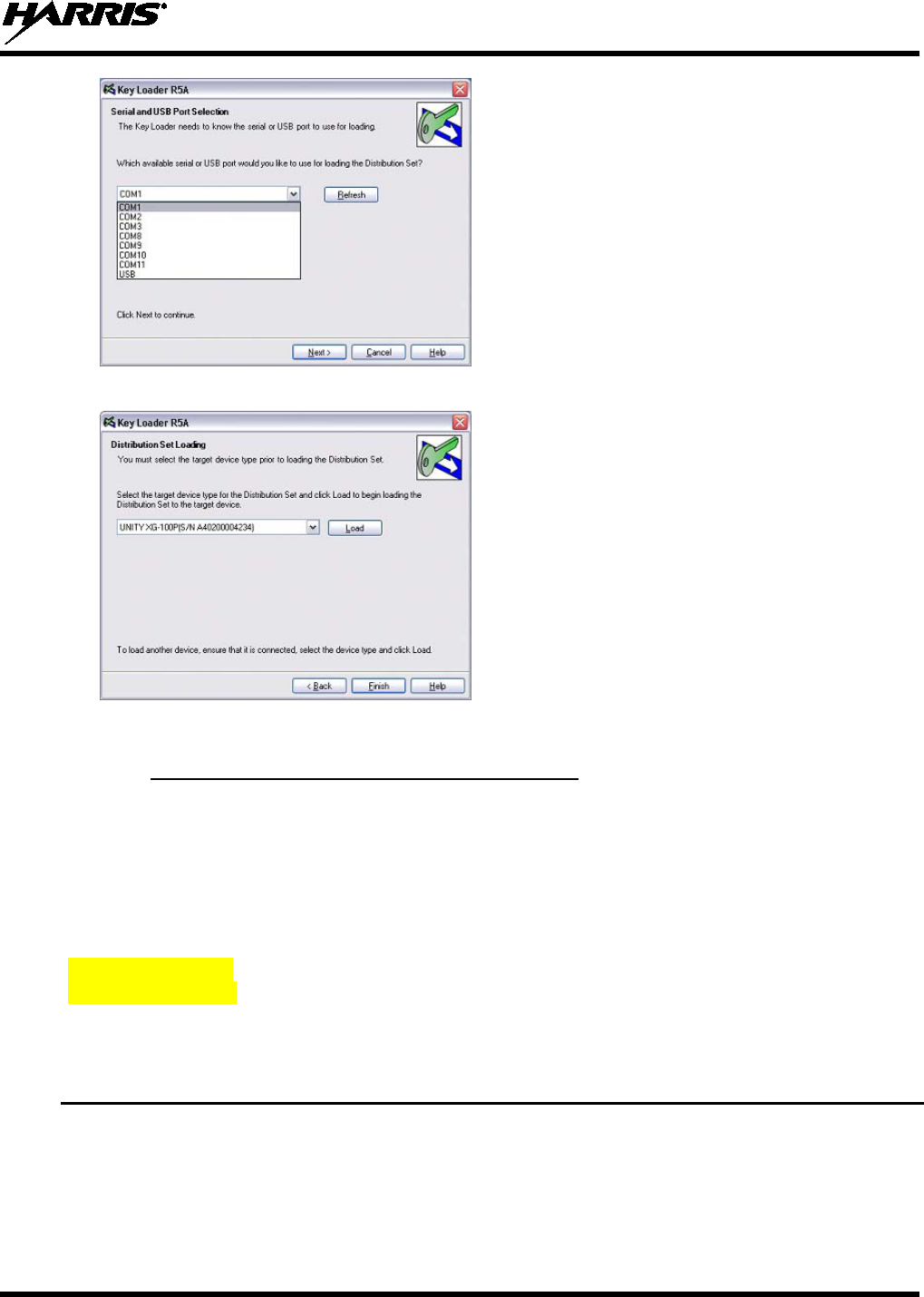
Insert graphic cable
connected to mobile. 1. Power on KVL 3000 Plus.
2. Connect KVL 3000 Plus to XG-100M using a 12082-0400-A1 cable.
NOTE: Once the KVL 3000 Plus is connected, a keyset is established whether
the keys are loaded or not. You will need to zeroize to bring the XG-100M to a
fully zeroized state (Section 7.4).
3. The key fill in progress screen will be displayed and the radio can accept
keys from the KVL.
14221-1200-2010
34
At the KVL 3000 Plus:
4. Select TARGET.
5. Select LOAD.
6. Select KEY.
7. Using ◄or ►, select:
• DES-OFB key
• AES-256 key
8. Press LOAD.
9. Verify that the KVL 3000 Plus screen displays LOADED
SUCCESSFULLY OK.
10. Select OK on the KVL 3000 Plus.
11. Repeat for additional keys.
12. Remove the KVL 3000 Plus cable from the radio.
7.3 LOAD KEYGROUPS
Make sure that valid keygroups have been created and stored in the KVL 3000 Plus before proceeding.
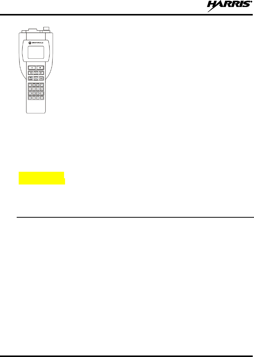
Insert graphic cable
connected to mobile. 1. Power on KVL 3000 Plus.
2. Connect KVL 3000 Plus to XG-100M connector using 12082-0400-A1
cable.
NOTE:
Once the KVL 3000 Plus is connected, a keyset is established whether
the keys are loaded or not. You will need to zeroize to bring the XG-100M to a
fully zeroized state (Section 7.4).
3.
The key fill in progress screen will be displayed and the radio can accept
keys from the KVL
14221-1200-2010
35
At the KVL 3000 Plus:
4. Select TARGET.
5. Select LOAD.
6. Select GROUP.
7. Using ◄or ►, select:
• DES-OFB keygroups
• AES-256 keygroups
8. Press LOAD.
9. Verify that the KVL 3000 Plus screen displays LOADED
SUCCESSFULLY OK.
10. Select OK on the KVL 3000 Plus.
11. Repeat for additional groups.
12. Remove the KVL 3000 Plus cable from the radio.
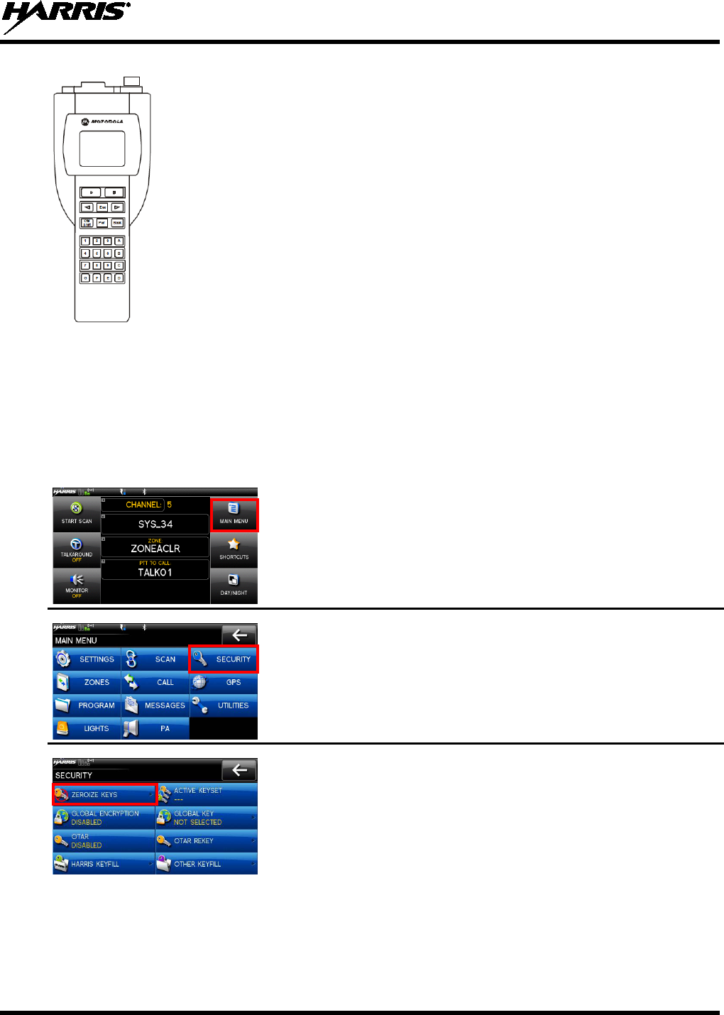
7.4 ZEROIZE ALL FROM RADIO
It may be necessary to remove the keys because of compromise or expiration.
1. At main display, select MAIN MENU.
2. Select SECURITY.
3. Select ZEROIZE KEYS.
14221-1200-2010
36
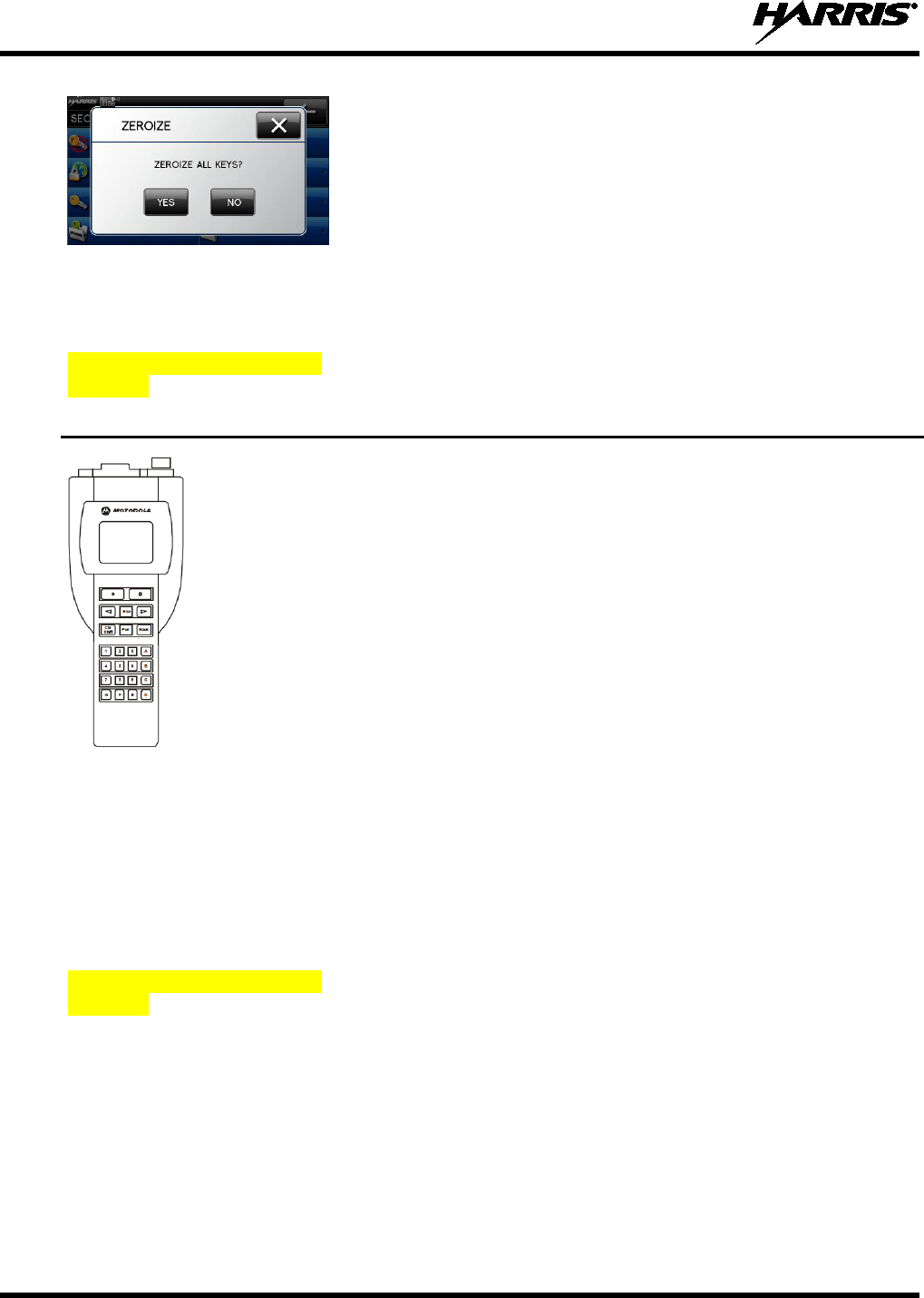
4. Select YES if you want to remove the keys.
NOTE: This will also remove the keysets.
7.5 ZEROIZE KEYS USING KVL 3000 PLUS
Refer to the KVL 3000 Plus User’s Guide for advanced instructions.
Insert graphic cable connected
to mobile. 1. Power on KVL 3000 Plus.
2. Connect KVL 3000 Plus to side XG-100M using 12082-0400-A1
cable.
At the KVL 3000 Plus:
3. Select TARGET.
4. Select ZERO.
5. Select KEY.
6. Using ◄ or ►, select the key to remove from the radio.
7. Press ZERO.
8. Verify that the KVL 3000 Plus screen displays ZEROIZED
SUCCESSFULLY OK.
9. Select OK on the KVL 3000 Plus.
10. Repeat for additional keys.
11. Remove the KVL 3000 Plus cable from the radio.
NOTE
: THE SELECTED KEY TO ZEROIZE IS DELETED
FROM ALL KEYSETS.
7.6 ZEROIZE KEYGROUPS USING KVL 3000 PLUS
Refer to the Motorola KVL 3000 Plus User's Guide for advanced instructions.
Insert graphic cable connected
to mobile. 1. Power on KVL 3000 Plus.
2. Connect KVL 3000 Plus to XG-100M using 12082-0400-A1
cable.
14221-1200-2010
37
At the KVL 3000 Plus:
3. Select TARGET.
4. Select ZERO.
5. Select GROUP.
6. Using ◄ or ►, select the key to remove from the radio.
7. Press ZERO.
8. Verify that the KVL 3000 Plus screen displays ZEROIZED
SUCCESSFULLY OK.
9. Select OK on the KVL 3000 Plus.
10. Repeat for additional keys.
11. Remove the KVL 3000 Plus cable from the radio.
NOTE
: THE SELECTED KEY TO ZEROIZE IS DELETED
FROM ALL KEYSETS.
7.7 ZEROIZE ALL FROM KVL 3000 PLUS
Refer to the KVL 3000 Plus User's Guide for advanced programming and setup instructions.
Insert graphic cable
connected to mobile. 1. Power on KVL 3000 Plus.
2. Connect KVL 3000 Plus to XG-100M using 12082-0400-A1 cable.
At the KVL 3000 Plus:
3. Select TARGET.
4. Select ZERO.
5. Select ALL.
6. Select YES.
7. Verify that the KVL 3000 Plus screen displays ZEROIZED
SUCCESSFULLY OK.
8. Select OK on the KVL 3000 Plus.
9. Remove the KVL 3000 Plus cable from the radio.
NOTE: This removes all keys but the keysets remain.
You will need to
perform a zeroize from the radio to bring the XG-100M
to a fully zeroized
state (Section 7.4).
7.8 GLOBAL ENCRYPTION
Global Encryption is enabled when encryption keys are loaded on the radio and the selected Zone/System
is encrypted. When Global Encryption is enabled on the radio, Global Key is used for all encrypted
transmissions until:
• Global Encryption is disabled
• A new mission fill is activated
14221-1200-2010
38
• The active keyset is changed
• The system is changed
Global Encryption behavior is available on all channels that support encrypted communications.
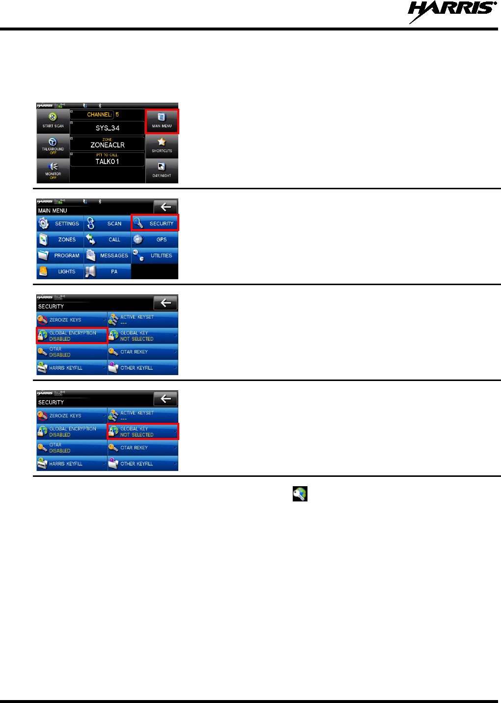
1. At main display, select MAIN MENU.
2. Select SECURITY.
3. Select GLOBAL ENCRYPTION to toggle to ENABLED.
4. Select GLOBAL KEY.
5. Select the global key.
6. The numbered keys are assigned in RPM.
7. The global key icon is displayed on the main display.
14221-1200-2010
39
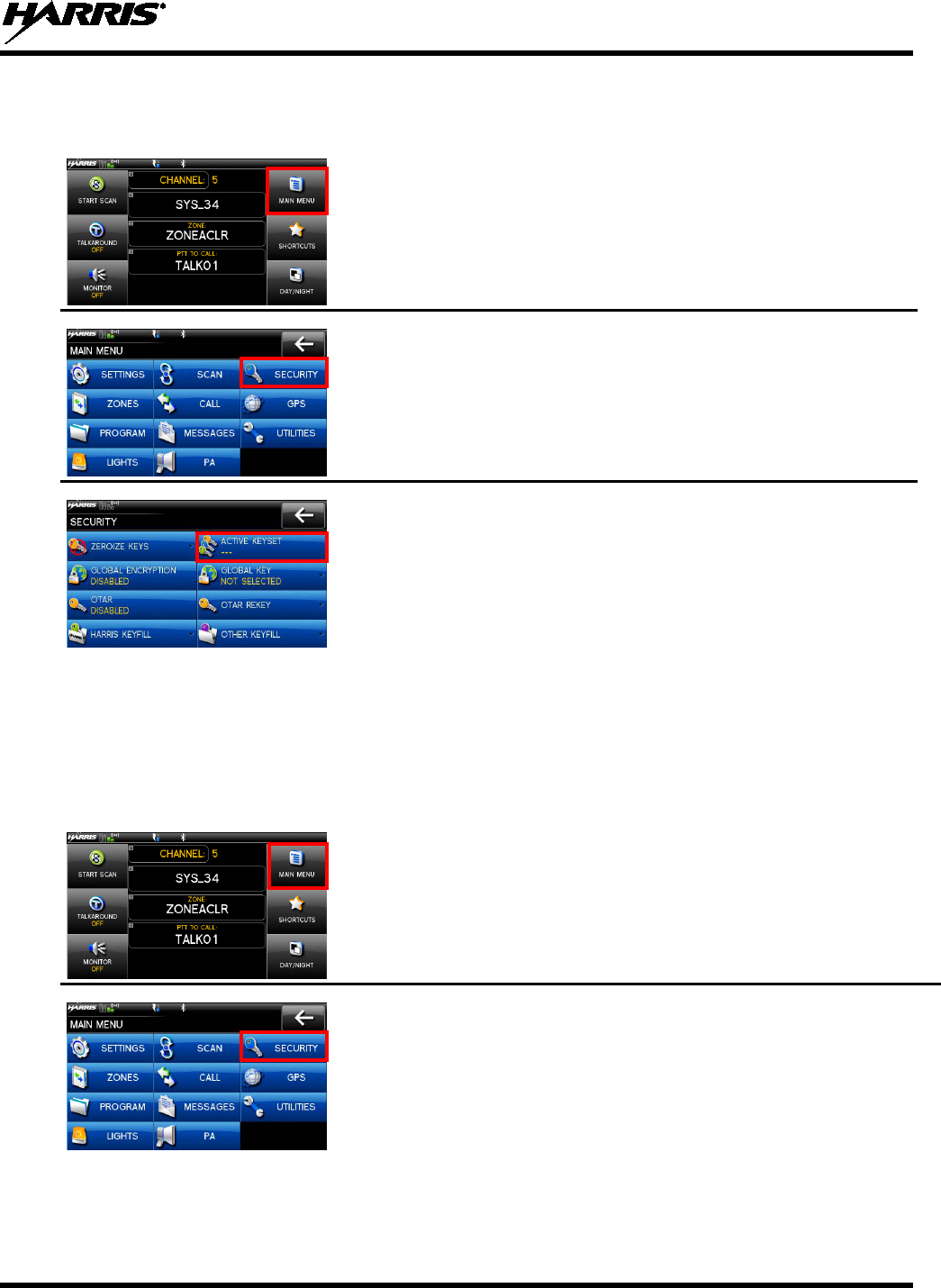
7.9 SELECT KEYSET
1. At main display, select MAIN MENU.
2. Select SECURITY.
3. Select ACTIVE KEYSET to toggle to the inactive keyset.
7.10 OTAR CONFIGURATION
OTAR is the over the air rekeying from a KMF and must be enabled for the digital only channel using
RPM. For OTAR operation, the appropriate KEKs must be loaded into the radio using the Harris UKEK
Loader or a KVL 3000.
The KMF Configuration must include the RSI of the KMF and the appropriate Message Number Period.
1. At main display, select MAIN MENU.
2. Select SECURITY.
14221-1200-2010
40
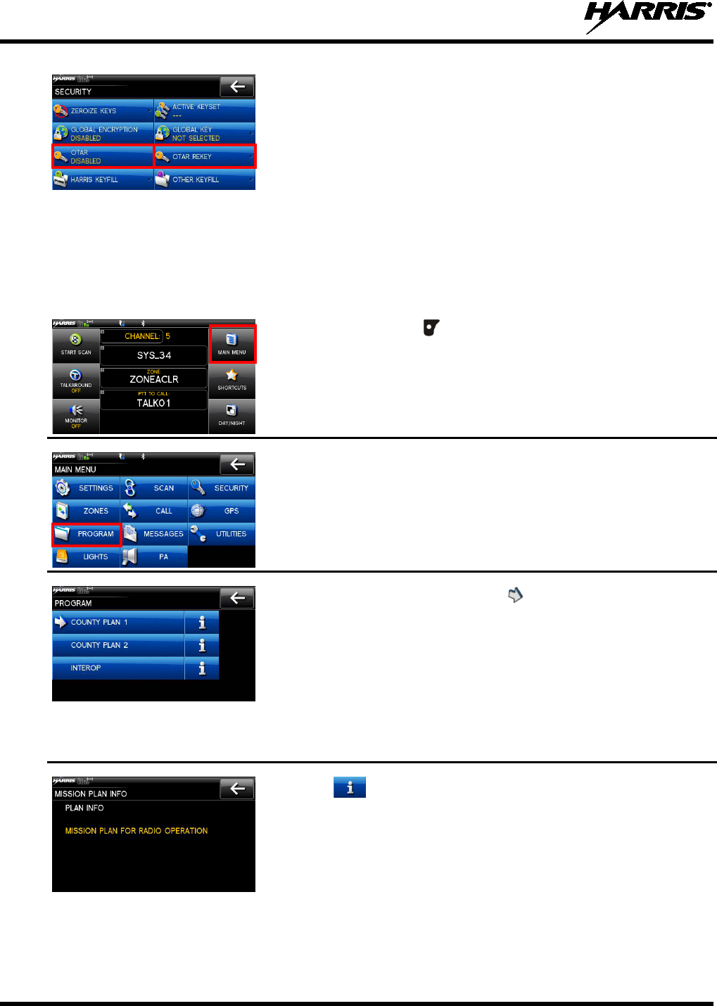
3. Select OTAR to toggle between ENABLED or DISABLED.
4. Select OTAR REKEY
to request that the KMF updates the keys in
the radio.
7.11 ACTIVATE/VIEW MISSION PLAN
Mission plans contain radio programming information such as frequencies, channels, stations, and talk
groups. Up to 10 different mission plans can be stored in the radio, but only one can be activated at a
time.
1. At main display, use for main menu.
2. Select PROGRAM.
3. Select the desired mission plan.
indicates the active mission
plan.
If a plan is activated, the
radio displays series of screens indicating
status, ending with a PLAN COMPLETE followed by name of plan.
NOTE: You
cannot activate a plan when the radio is transmitting an
emergency.
A MISSION PLAN FAILED
message may be displayed for errors
such as invalid syntax in the fill or some other invalid parameter.
4. Select to view mission plan information.
14221-1200-2010
41
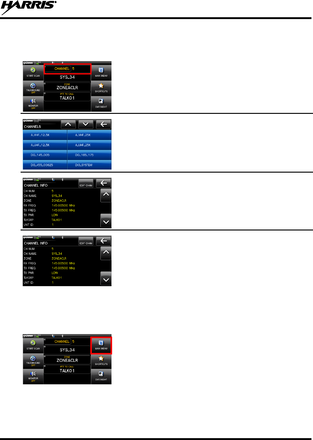
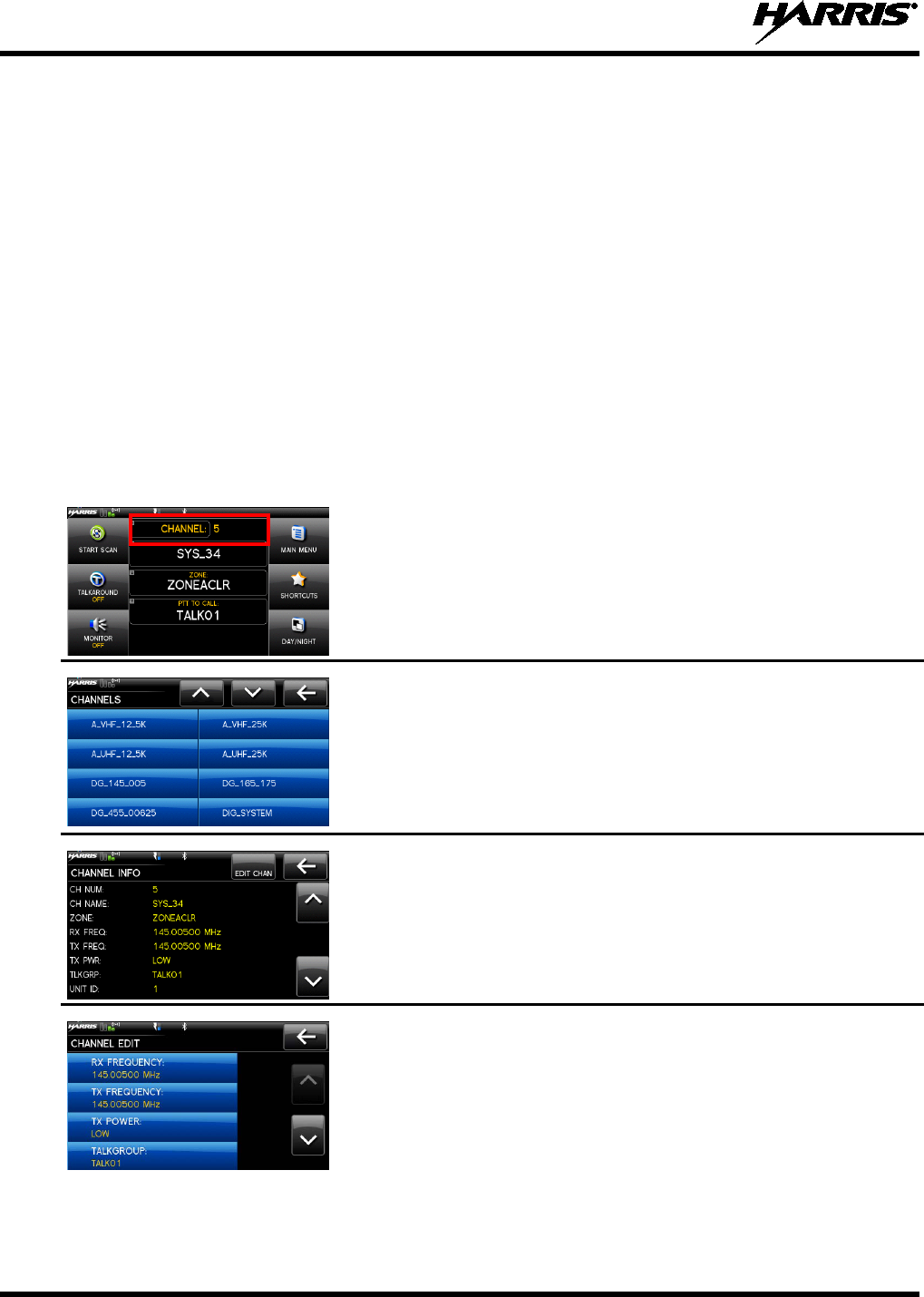
7.12 CH INFO MENU
The Channel Information (CH INFO) menu displays information about the currently selected channel.
Note that the information displayed varies between conventional and trunked systems.
1. At main display,
select the channel to display the available
channels.
2. Select a channel to view the channel info.
3. Additional settings can be found by scrolling down.
CONVENTIONAL ONLY:
4. Select EDIT CHAN.
5. Enter password.
NOTE: Password remains active until power cycle.
Refer to Section 8.2.
7.13 SETTINGS MENU
The settings menu allows you to change global radio settings such as audio, display, GPS, bluetooth,
clock, and battery settings.
1. At main display, select MAIN MENU.
14221-1200-2010
42
2. Select SETTINGS.
Refer to the Sections 7.13.1
for more information on the available
settings.
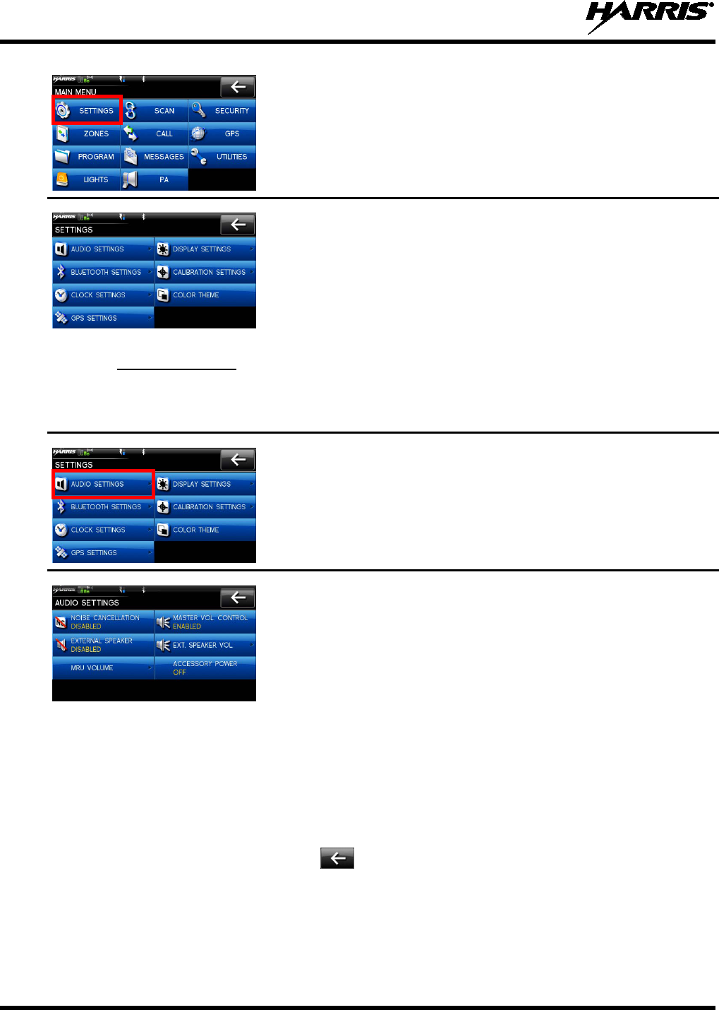
7.13.1 Audio Settings
Set audio settings such as speaker mute, noise cancellation, PTT, and tones.
1.
Enter the Settings Menu.
2. Select AUDIO SETTINGS.
3. Select and change settings as desired:
• NOISE CANCELLATION -
Enable or disable noise
cancellation. Noise cancellation reduces background noise
during transmit.
• EXTERNAL SPEAKER - Enable or disable
the external
speaker.
• MRU VOLUME – Adjust the radio volume.
• MASTER VOL CONTROL –
Enable or disable the master
volume control.
• EXT. SPEAKER VOL – Adjust the external speaker volume.
• ACCESSORY POWER – Turn accessory power on or off.
4. Use to exit menu.
14221-1200-2010
43
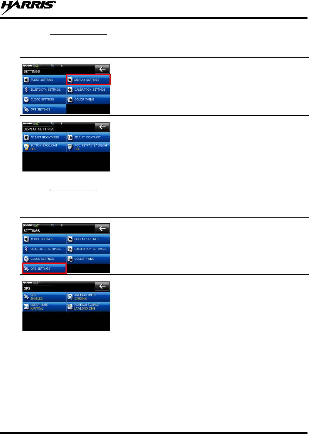
7.13.2 Display Settings
1.
Enter Settings Menu.
2. Select DISPLAY SETTINGS.
3. Select and change settings as desired.
7.13.3 GPS Settings
1. Enter Settings Menu.
2. Select GPS SETTINGS.
3. Select and change settings as desired:
• GPS - Enable or disable internal GPS.
• LINEAR UNITS -
Set unit of measurement of displayed
linear units: STATUTE, METRIC, or NAUTICAL.
• ANGULAR UNITS -
Set unit of measurement of displayed
angular units: CARDINAL, DEGREES, or MILS.
• POSITION FORMAT-
Set format of displayed position
information:
Latitude/Longitude Degrees Minutes Seconds
(LAT/LONG DMS), LAT/LONG DM,
Military Grid
Reference System (MGRS),
or Universal Transverse Mercator
(UTM).
14221-1200-2010
44
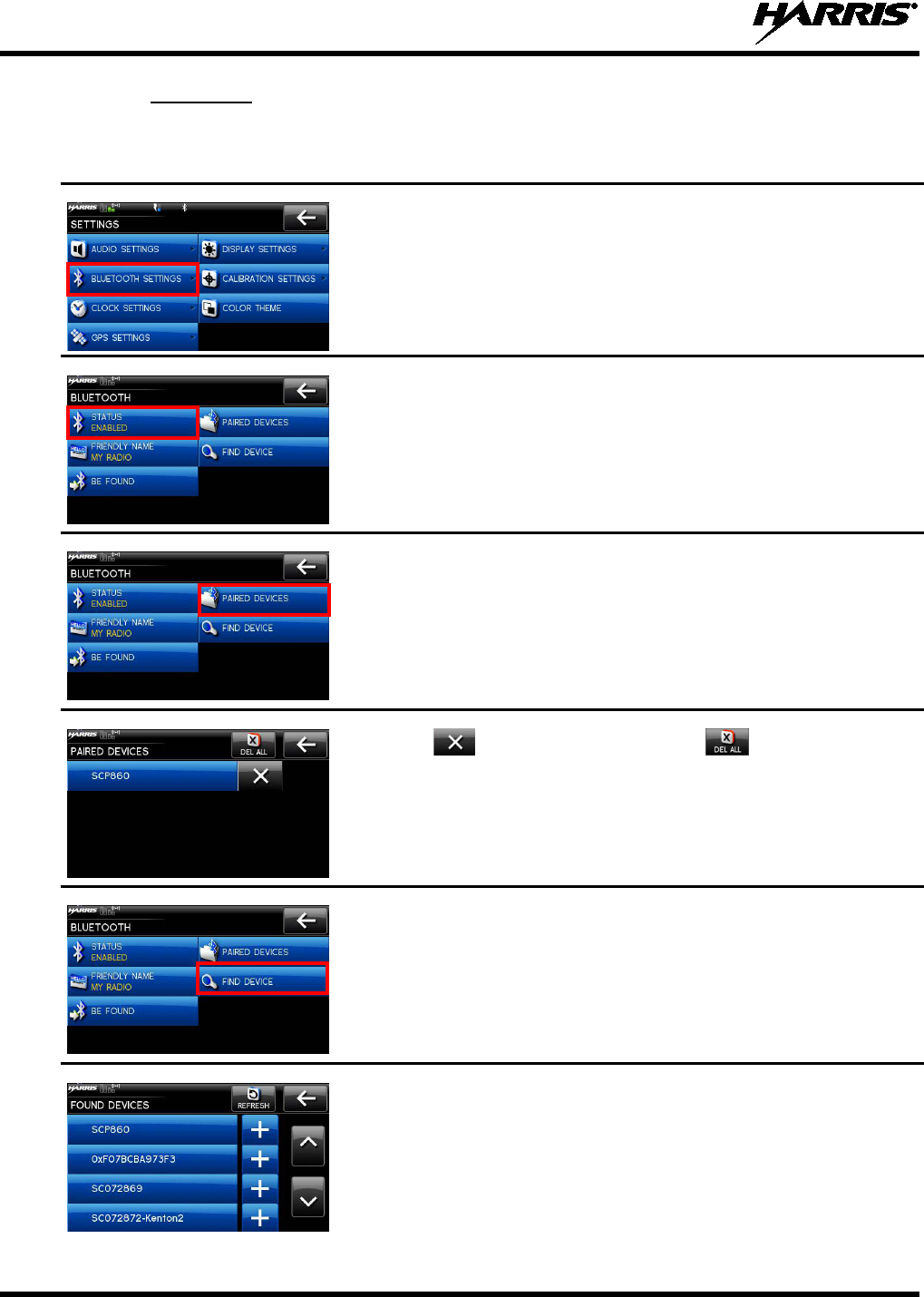
7.13.4 Bluetooth
Bluetooth settings only appear if enabled in RPM.
1.
Enter Settings Menu.
2. Select BLUETOOTH SETTINGS.
3. Select STATUS to toggle between ENABLED and DISABLED.
4. Select PAIRED DEVICES
to view all Bluetooth devices currently
paired with the radio.
5. Select to delete a device. Select
to delete all paired
devices.
6. Select FIND DEVICE. This is used to pair the radio with another
Bluetooth device.
7.
Make sure device being paired is powered on and has discovery
mode enabled in order to pair with the XG-100M.
8. Select the desired device.
14221-1200-2010
45
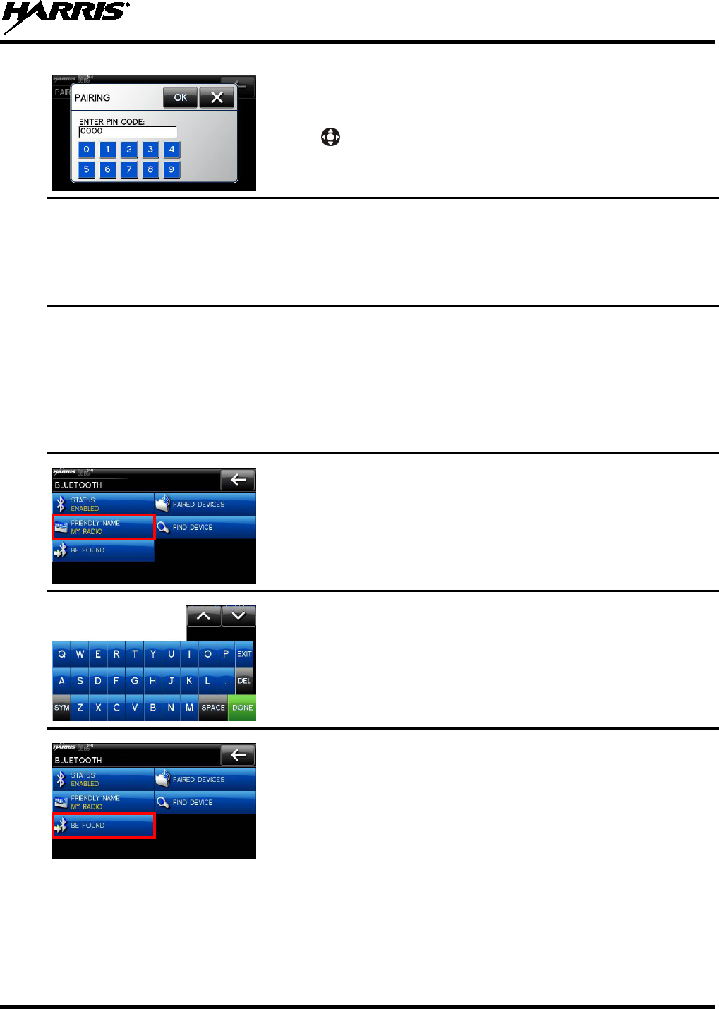
For Bluetooth 2.0 devices, a pin code screen appears.
9. Enter pin code.
10. Use to select OK.
For Bluetooth 2.1 devices, an accept/deny screen appears.
11. Select ACCEPT.
NOTE:
You will also need to accept the passkey on the Bluetooth®
2.1 device as well.
A message appears when pairing is complete.
12. Select OK.
The paired device is then displayed under the paired devices list.
NOTE:
Names containing extended ASCII characters may not display
correctly.
13. Select FRIENDLY NAME
. This is the Bluetooth® name assigned
to the radio. The friendly name used by RPM
will overwrite this
setting.
14.
Enter the name from the keypad displayed on the touch screen and
select DONE when finished.
15. Select BE FOUND to
turn on discovery mode so other Bluetooth
devices can discover the XG-100M.
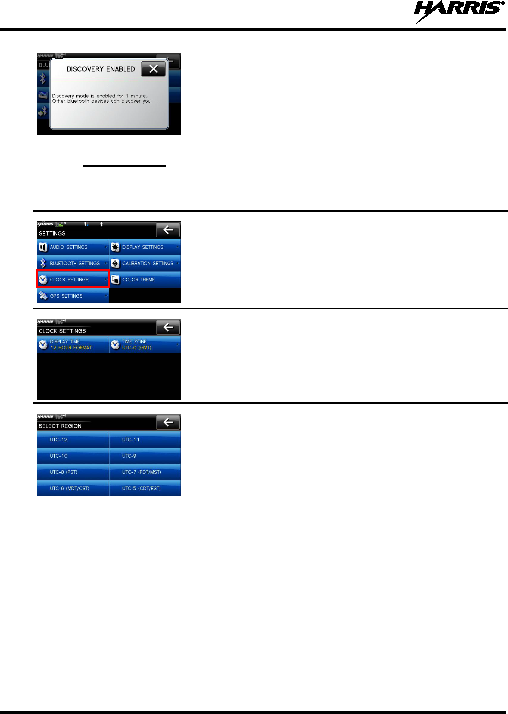
14221-1200-2010
46
16. Discovery mode will be enabled for one minute.
7.13.5 Clock Settings
1. Enter Settings Menu.
2. Select CLOCK SETTINGS.
3. Select the setting to change.
• DISPLAY TIME - Set 12 or 24 hour time display format.
• TIME ZONE -
Set time zone relative to Universal Time
Coordinated (UTC).
14221-1200-2010
47
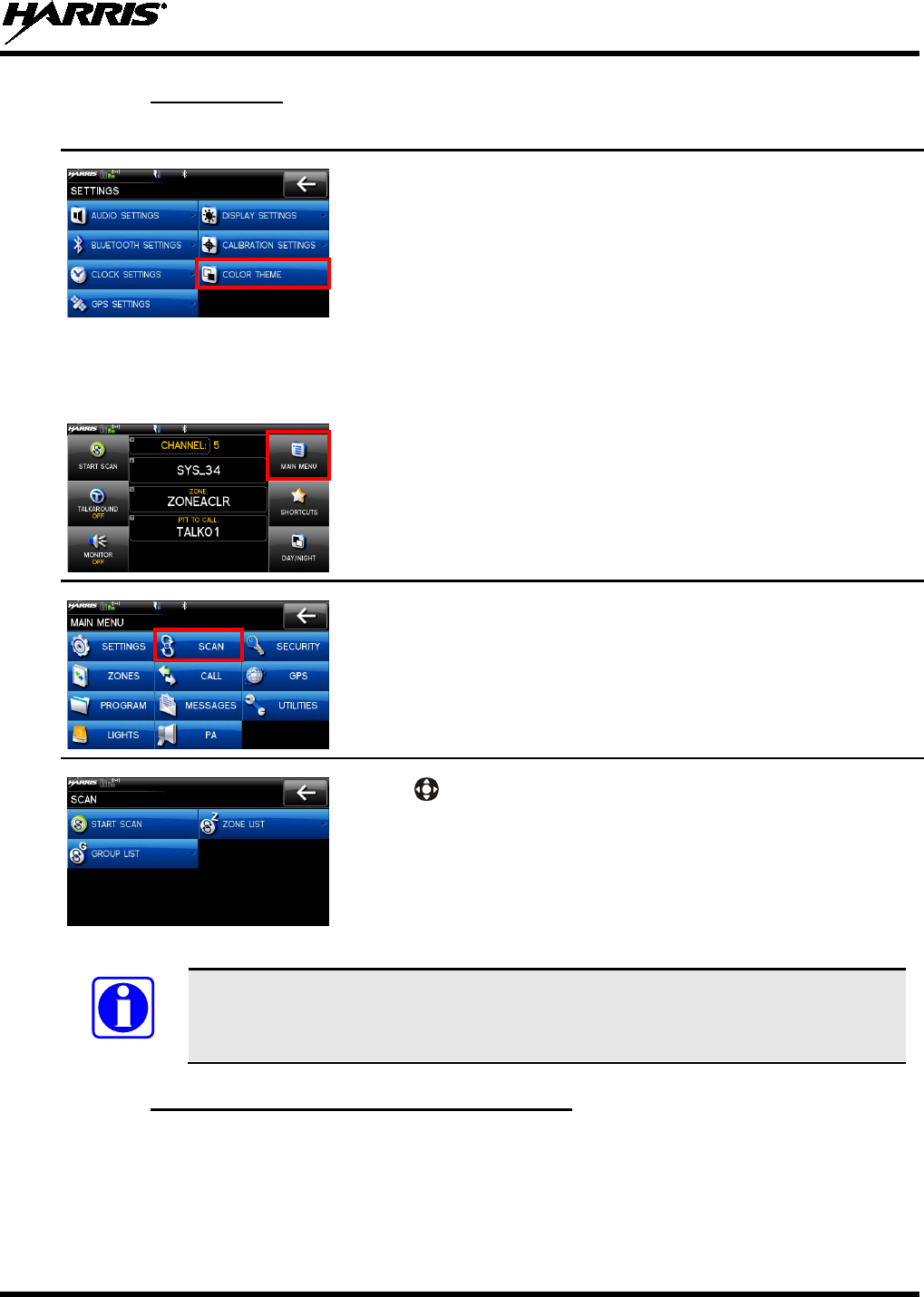
7.13.6 Color Theme
1. Enter Settings Menu (see Section 7.13).
2. Select COLOR THEME.
7.14 SET UP SCAN
These procedures are used to set up the scan list, home channels, and priority channels. Refer to 6.13.
1. At main display, select MAIN MENU.
2. Select SCAN.
3. Use to highlight and select ZONE LISTS or GROUP LISTS
and refer to the following sections.
NOTE
When using Preemptive Priority Scan, the frequencies in the list need to be unique.
7.14.1 Home, Priority 1, and Priority 2 Channels
7.14.1.1 Home Channel
This is the channel you transmit on by default when you press PTT while the radio is actively scanning
and is not responding to a just received call. Responding to a call the radio just received while scanning is
called hang time. If hang time is set to 0 in RPM, the radio always transmits on the home channel in scan.
14221-1200-2010
48
7.14.1.2 Priority 1 Channel
This channel will be scanned more often than other channels in the list and will be scanned in between
every other channel in the scan list. An example scan sequence would be P1 (priority 1), C2, P1, C3, P1,
C4, etc. Also, the priority channel will be scanned even while actively receiving on a non-priority
channel. For example, if the radio is actively receiving on C3 and activity is detected on P1, the radio will
drop C3 and switch to P1.
7.14.1.3 Priority 2 Channel
This channel will also be scanned more often than others. An example scan sequence would be P1, C2,
P1, C3, P1, C4, P2, C5, P1, C6, P1, C7, P1, C8, P2, C9 etc. Also, this channel will be scanned even while
actively receiving on a non-priority channel. For example, if the radio is actively receiving on C3 and
activity is detected on P2, the radio will drop C3 and switch to P2. Additionally, activity on P1 can also
preempt P2, but P2 cannot preempt P1.
7.14.2 Zone Scan
Zone scan is conventional only and consists of all channels in a zone that are selected as scan channels
when generating a mission plan with RPM. Depending on scan options selected in RPM, zone scan lists
may be modified to include or exclude channels.
Analog channels using different receive frequencies may be added in any combination of squelch type up
to the limits of the size of the scan list.
7.14.3 Group Scan
Group scan is trunked only and allows the radio to monitor many groups simultaneously, permitting the
user to both monitor and receive calls from these groups. Depending on scan options selected in RPM,
group scan lists may be modified to include or exclude groups.
7.14.4 Vote Scan
If vote scan is enabled via RPM, the radio automatically selects the strongest signal ensuring that the best
audio quality is delivered to the user. If vote scan is enabled, the radio is always scanning. You cannot
stop scanning, start normal scanning, or monitor the channel. There is an icon in the upper status bar
indicating that the radio is vote scanning.
NOTE
If Talkaround is enabled, Vote Scan is turned off.
14221-1200-2010
49
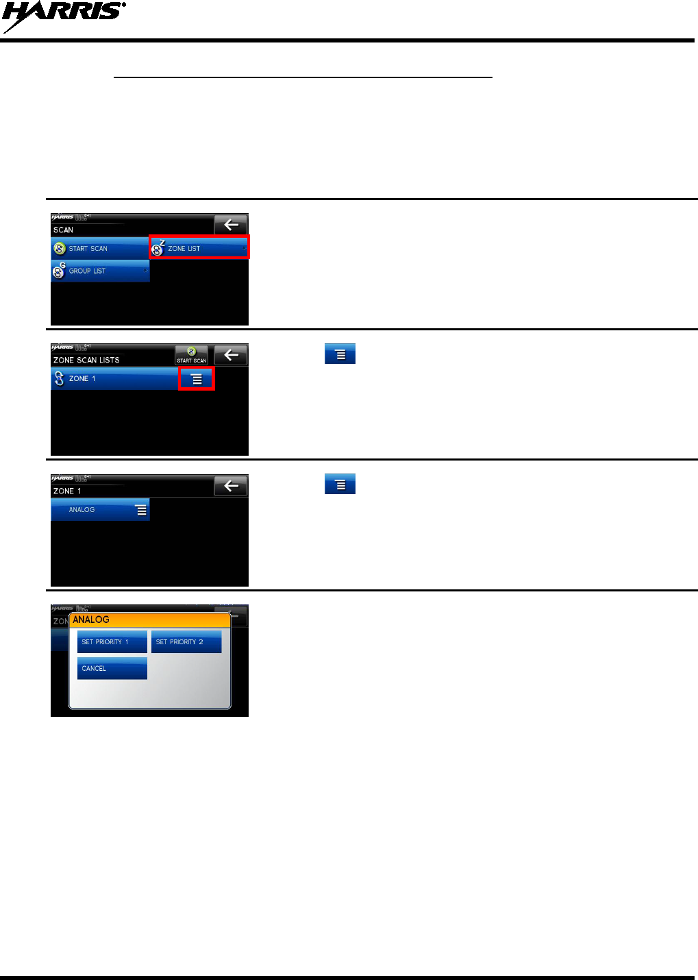
7.14.5 Set or Remove Priority 1 and Priority 2 Channels
Priority channels are scanned more often than non-priority channels. Note that P1 and P2 can only be set
if configured as “Keypad” and the scan list is not set to “Fixed” in RPM.
Zone scan configuration screens are shown below. Group scan configuration is similar.
1. Enter Set up Scan (see Section 7.14) and select group lists or zone
list.
2. Select the scan list.
3. Select .
4. Select next to the channel.
5. Select SET PRIORITY 1, SET PRIORITY 2, or CANCEL.
14221-1200-2010
50
7.14.6 Wide Area System Scan (P25 Trunked Only)
Wide Area System Scan (WASCAN) causes the radio to roam across mobile systems when the currently
selected system's control channel is lost. The radio will scan the control channels of other systems.
1. At main display, select MAIN MENU.
2. select SCAN.
3. Select SITE ROAMING.
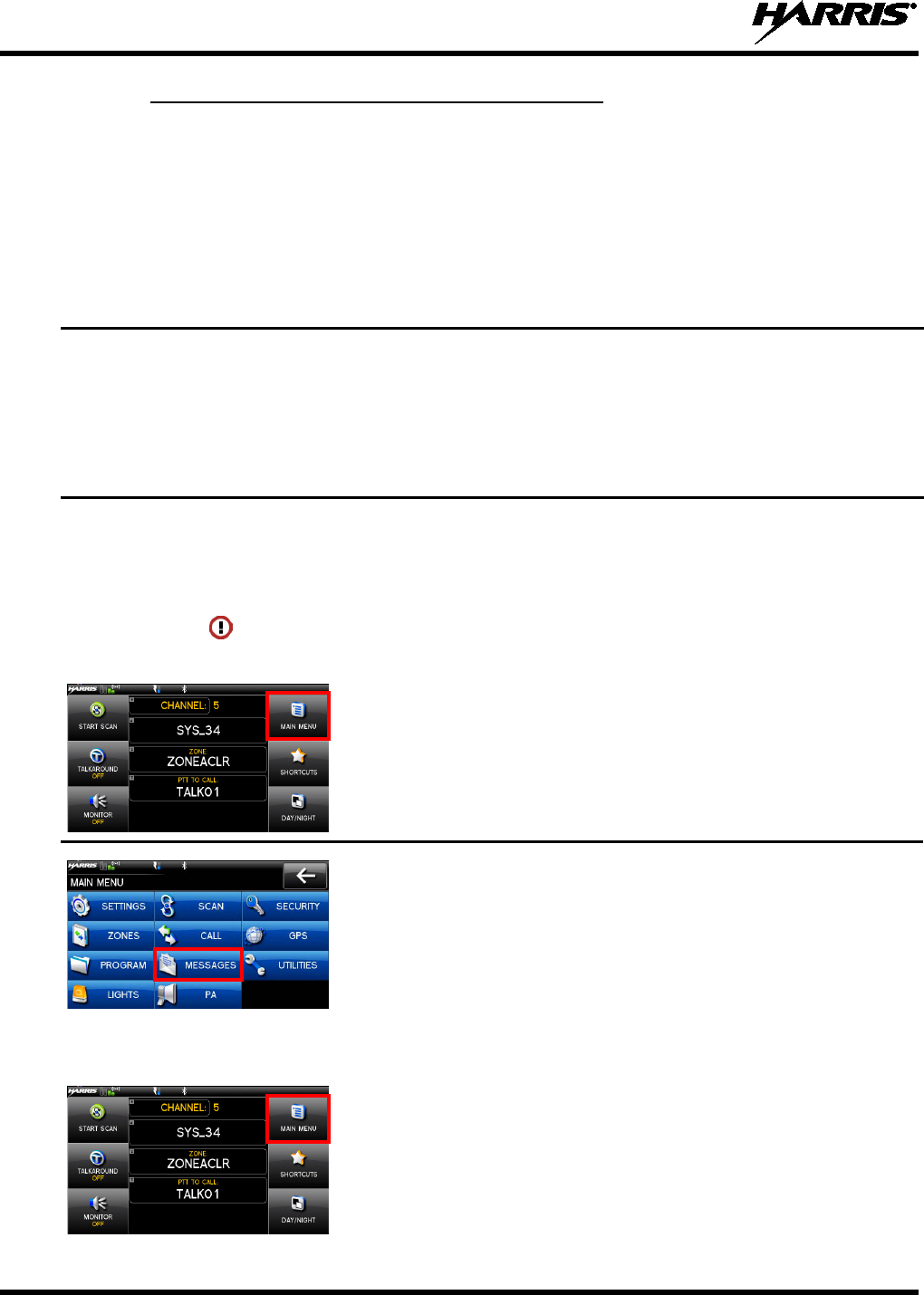
7.15 MESSAGE MENU
If the alert icon is displayed on the main display, you can view details about the alert from the
MESSAGES MENU:
1. At main display, select MAIN MENU.
2. Select MESSAGES. Observe messages in display.
NOTE: The alert icon goes away when you go to the message display
(unless a new fault occurs).
7.16 UTILITIES MENU
1. At main display, select MAIN MENU.
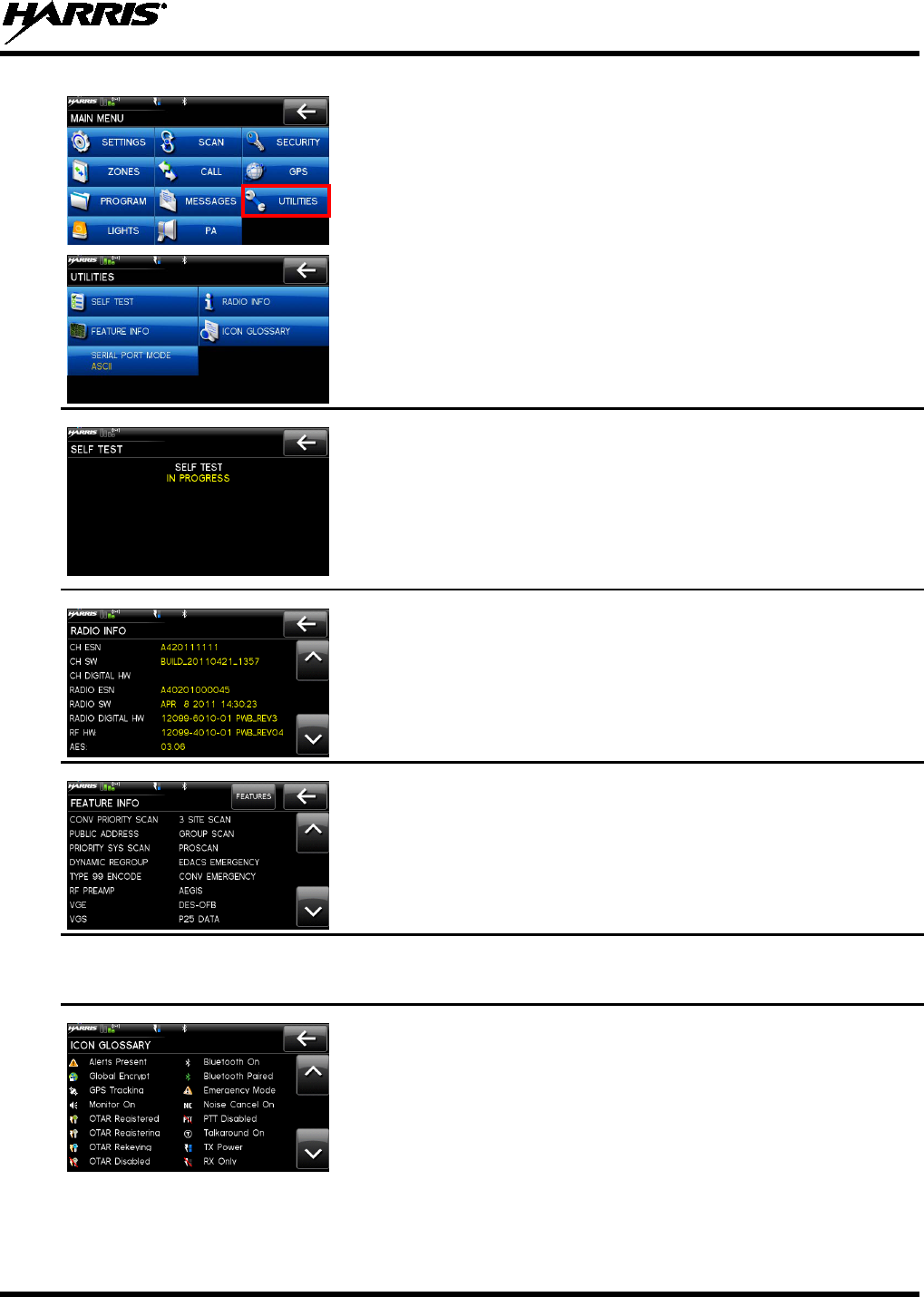
14221-1200-2010
51
2. Select UTILITIES.
3. Select SELF TEST to run a series of internal radio tests.
Status screen appears while testing followed by a screen with passed or
failed results.
4. Select RADIO INFO to view radio information such as software
and firmware revisions.
5. Observe radio information display.
6. Select FEATURE INFO to view the features enabled on the radio.
7. Select SERIAL PORT MODE to specify the serial port.
8. Select ICON GLOSSARY
to view descriptions of the icons
displayed by the radio.
14221-1200-2010
52
8. PROGRAMMING
This section provides information on front panel programming. Programming can also be accomplished
by creating a plan using a computer with RPM version R6A or later installed.
8.1 PROGRAMMING VIA RPM
Radio Personality Manager (RPM) or is used for the bulk of programming the XG-100M. With RPM, you
can fully program the XG-100M using cable 12082-0410-A1.
8.2 EDIT CHANNEL (CONVENTIONAL ONLY)
Channels can be edited from the Channel Information (CH INFO) menu display. Most of the displayed
channel parameters can be modified here. Channel edits persist across a power cycle. Loading a mission
plan clears any channel edits.
Available parameters vary depending on whether the channel is a digital or analog channel. A digital
channel allows you to receive digital or analog signals. When transmitting on a digital channel, you can
transmit either a digital or analog signal, depending on how the channel is programmed.
1. At main display,
select the channel to display the available
channels.
2. Select a channel to view the channel info.
3. Select EDIT CHAN.
4. Enter password.
NOTE: Password remains active until power cycle.
5. For digital channel, modify remaining channel settings:
• TX FREQUENCY - Transmit frequency.
• TX POWER –
Transmit power. Toggle between LOW and
HIGH.
• TALKGROUP –
Select a talkgroup for the channel.
Talkgroup name cannot be set here.
• RX NAC - Network Access Code (NAC) ra
dio uses for
Normal squelch in receive.

14221-1200-2010
53
• TX NAC -
NAC radio transmits to break Normal squelch on
receiving radio.
• P25 SQUELCH –
Select type the radio uses in receive. Select
NORMAL, SELECTIVE, or MONITOR.
• RX CHAN GUARD –
Squelch type radio uses in receive.
Select Noise, CTCSS, or CDCSS. For a digital channel, the
RX CHAN GUARD is used to receive from a Conventional
analog channel that is on the same frequency and uses the
selected Channel Guard.
RX CODE - Code radio looks for to unmute the speaker
on the receiving radio when CDCSS squelch is used in
conventional mode.
RX TONE - Tone radio looks for to unmute the speaker
on the receiving radio when CDCSS squelch is used in
conventional mode.
6. For analog channel, modify remaining channel settings:
• TX FREQUENCY - Transmit frequency.
• TX POWER –
Transmit power. Toggle between HIGH and
LOW.
• RX CHAN GUARD –
Squelch type radio uses in receive.
Select Noise, CTCSS, or CDCSS.
RX TONE - Tone radio uses to break selective squelch on
receiving radio. This is available when RX squelch is set to
CTCSS.
RX CODE - Code radio uses to break selective squelch on
receiving radio. This is available when RX squelch is set to
CDCSS.
• TX CHAN GUARD –
Squelch type radio uses in transmit.
Select None, CTCSS, or CDCSS.
TX TONE -
Tone sent by transmitting radio to allow
receiving radio to unmute when CDCSS squelch is used in
conventional mode.
TX CODE -
Code sent by transmitting radio to allow
receiving radio to unmute when CDCSS squelch is used in
conventional mode.
Table 8-1: Valid Frequencies
FREQUENCY RANGE FREQUENCY RESOLUTION
136 - 174 MHz
2500, 5000, or 6250 Hz
380 - 520 MHz
2500, 5000, or 6250 Hz
764 - 870 MHz
6250 kHz
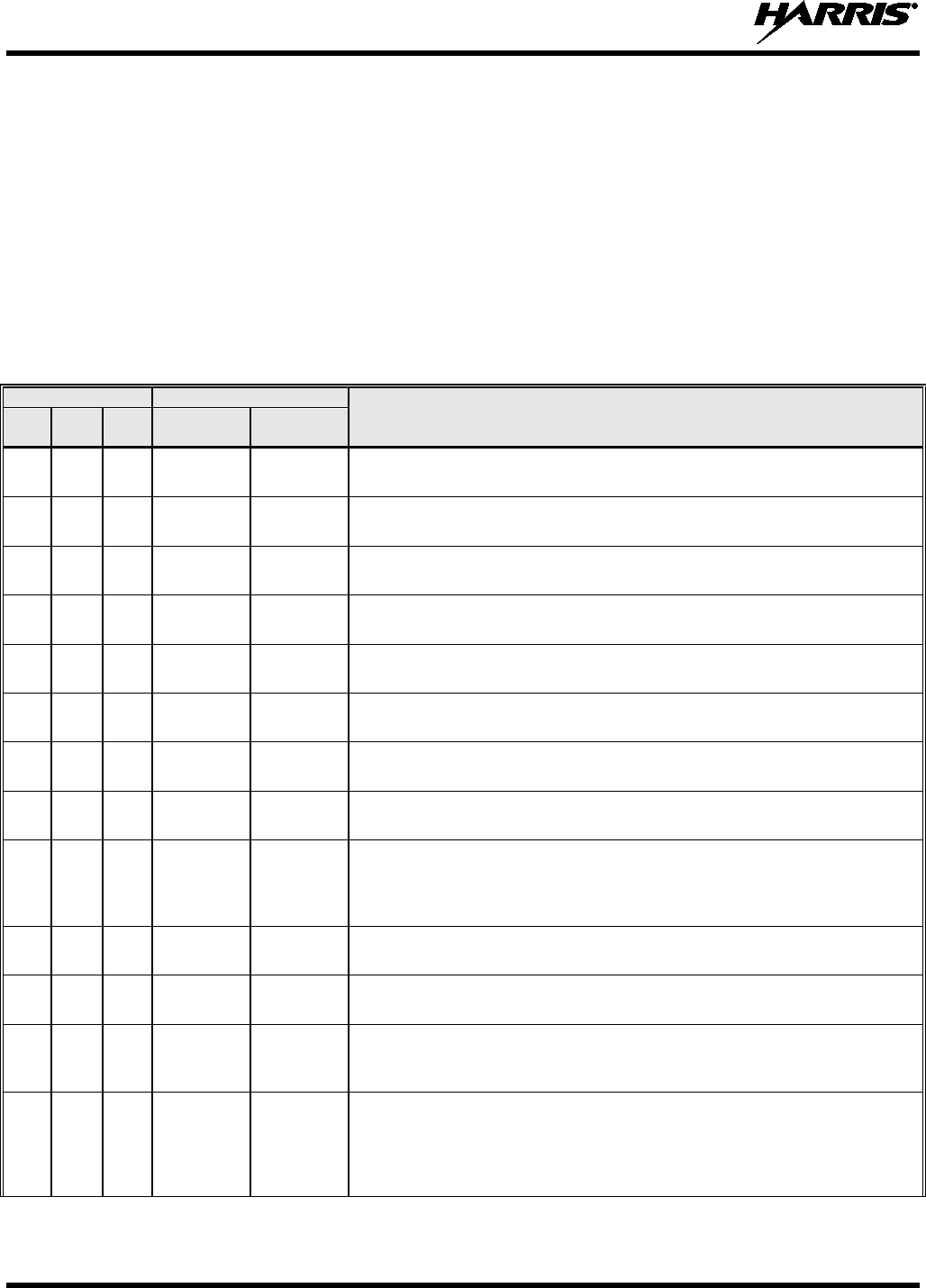
14221-1200-2010
54
9. REFERENCE
9.1 MARINE FREQUENCIES
Refer to Table 9-1: Marine Frequencies for a list of maritime frequencies per United States Coast Guard
(USCG), National Oceanic and Atmospheric Administration (NOAA), and Canadian Department
Fisheries and Oceans, August 2009:
• United States (US)
• International (Intl)
• Canada (CA)
Table 9-1: Marine Frequencies
CHANNEL
FREQUENCY
CHANNEL USAGE
US INTL CA
SHIP
(MHZ)
SHORE
(MHZ)
1
1
T: 156.05
R: 160.65
T: 160.65
R: 156.05
International: Public Correspondence, Port Operations
1a T/R:
156.05
T/R:
156.05
US: Port Operations and Commercial, Vessel Traffic Service (VTS). New
Orleans/Lower Mississippi area.
2 2 T: 156.10
R: 160.70
T: 160.70
R: 156.10
International: Public Correspondence, Port Operations
3
3
T: 156.15
R: 160.75
T: 160.75
R: 156.15
International: Public Correspondence, Port Operations
4
T: 156.20
R: 160.80
T: 160.80
R: 156.20
International: Public Correspondence, Port Operations
4a
T/R:
156.20
T/R:
156.20
Canada: Department Fisheries Ocean (DFO)/Canadian Coast Guard only in
British Columbia coast area. Commercial fishing in east coast area
5 T: 156.25
R: 160.85
T: 160.85
R: 156.25
International: Public Correspondence, Port Operations
5a 5a T/R:
156.25
T/R:
156.25
US: Port Operations or VTS in Houston, New Orleans and Seattle areas.
6
6
6
T/R:
156.30
T/R:
156.30
US: Intership Safety
International: Intership
Canada: May be used for search and rescue communications between ships
and aircraft.
7 T: 156.35
R: 160.95
T: 160.95
R: 156.35
International: Public Correspondence, Port Operations
7a
7a
T/R:
156.35
T/R:
156.35
US: Commercial
8
8
8
T/R:
156.40
T/R:
156.40
US: Commercial (Intership only)
International: Intership
Canada: Also assigned for intership in the Lake Winnipeg area.
9 9 9 T/R:
156.45 T/R:
156.45 US: Boater Calling. Commercial and Non-Commercial.
International: Intership, Port Operations
Canada: Commercial - British Columbia coast area.
May be used to communicate with aircraft and helicopters in predominantly
maritime support operations.

14221-1200-2010
55
Table 9-1: Marine Frequencies
CHANNEL
FREQUENCY
CHANNEL USAGE
US INTL CA
SHIP
(MHZ)
SHORE
(MHZ)
10
10
10
T/R:
156.50
T/R:
156.50
US: Commercial
International: Intership, Port Operations
Canada: Commercial - British Columbia coast area.
May also be used for communications with aircraft engaged in coordinated
search and rescue and antipollution operations.
11 11 11 T/R:
156.55 T/R:
156.55 US: Commercial. VTS in selected areas.
International: Port Operations
Canada: VTS - British Columbia coast area.
Also used for pilotage purposes.
12
12
12
T/R:
156.60
T/R:
156.60
US: Port Operations. VTS in selected areas.
International: Port Operations
Canada: VTS - British Columbia coast area.
Also used for pilotage purposes.
13
13
13
T/R:
156.65
T/R:
156.65
US: Intership Navigation Safety (Bridge-to-bridge). Ships >20m length
maintain a listening watch on this channel in US waters.
International: Intership, Port Operations
Canada: VTS - British Columbia coast area.
Also used for pilotage purposes.
14 14 14 T/R:
156.70 T/R:
156.70 US: Port Operations. VTS in selected areas.
International: Port Operations
Canada: VTS - British Columbia coast area.
Also used for pilotage purposes.
15
15
15
T/R:
156.75
T/R:
156.75
US: Environmental (Receive only). Used by Class C Emergency Position-
Indicating Radio Beacons (EPIRBs).
International: Intership, Port Operations
Canada: Port operations and Ship Movement - British Columbia coast area.
All operations limited to 1-watt maximum power. May also be used for on-
board communications.
16
16
16
T/R:
156.80
T/R:
156.80
US: International Distress, Safety and Calling. Ships required to carry radio,
US Coast Guard (USCG), and most coast stations maintain a listening watch
on this channel.
International: International Distress, Safety and Calling
Canada: International Distress, Safety and Calling
17
17
17
T/R:
156.85
T/R:
156.85
US: State Control
International: Intership, Port Operations
Canada: Port operations and Ship Movement - British Columbia coast area.
All operations limited to 1 watt maximum power. May also be used for on-
board communications.
18 T: 156.90
R: 161.50
T: 161.50
R: 156.90
International: Public Correspondence, Port Operations
18a 18a T/R:
156.90
T/R:
156.90
US: Commercial
Canada: Towing - British Columbia coast area.
19
T: 156.95
R: 161.55*
T: 161.55*
R: 156.95
International: Public Correspondence, Port Operations
19a
19a
T/R:
156.95
T/R:
156.95
US: Commercial
Canada: DFO/Canadian Coast Guard. Pacific Pilots - British Columbia coast
area.

14221-1200-2010
56
Table 9-1: Marine Frequencies
CHANNEL
FREQUENCY
CHANNEL USAGE
US INTL CA
SHIP
(MHZ)
SHORE
(MHZ)
20
20
20
T: 157.00
R: 161.60
T: 161.60
R: 157.00
US: Port Operations (Duplex)
International: Public Correspondence, Port Operations
Canada: Port operations only with 1 watt maximum power.
20a
T/R:
157.00
T/R:
157.00
US: Port Operations
21
T: 157.05
R: 161.65*
T: 161.65*
R: 157.05
International: Public Correspondence, Port Operations
21a
21a
T/R:
157.05
T/R:
157.05
US: US Coast Guard only
Canada: DFO/Canadian Coast Guard only.
21b
- -
T/R:
161.65
22 T: 157.10
R: 161.70
T: 161.70
R: 157.10
International: Public Correspondence, Port Operations
22a
22a
T/R:
157.10
T/R:
157.10
US: Coast Guard Liaison and Maritime Safety Information Broadcasts.
Broadcasts announced on channel 16.
Canada: For communications between Canadian Coast Guard and non-
Canadian Coast Guard stations only.
23 23 T: 157.15
R: 161.75
T: 161.75
R: 157.15
International: Public Correspondence, Port Operations
23a
T/R:
157.15
T/R:
157.15
US: US Coast Guard only
23b
- -
T/R:
161.75
Canada: Continuous Marine Broadcast (CMB) service.
24
24
24
T: 157.20
R: 161.80
T: 161.80
R: 157.20
US: Public Correspondence (Marine Operator)
International: Public Correspondence, Port Operations
25 25 25 T: 157.25
R: 161.85 T: 161.85
R: 157.25 US: Public Correspondence (Marine Operator)
International: Public Correspondence, Port Operations
Canada: Also assigned for operations in the Lake Winnipeg area.
25b
T/R:
161.85
26
26
26
T: 157.30
R: 161.90
T: 161.90
R: 157.30
US: Public Correspondence (Marine Operator)
International: Public Correspondence, Port Operations
27
27
27
T: 157.35
R: 161.95
T: 161.95
R: 157.35
US: Public Correspondence (Marine Operator)
International: Public Correspondence, Port Operations
28 28 28 T: 157.40
R: 162.00
T: 162.00
R: 157.40
US: Public Correspondence (Marine Operator)
International: Public Correspondence, Port Operations
28b - - T/R:
162.00
Canada: Continuous Marine Broadcast (CMB) service.
60
60
T: 156.025
R: 160.625
T: 160.625
R: 156.025
International: Public Correspondence, Port Operations
61
T: 156.075
R: 160.675
T: 160.675
R: 156.075
International: Public Correspondence, Port Operations
61a
61a
T/R:
156.075
T/R:
156.075
Canada: DFO/Canadian Coast Guard only in British Columbia coast area.

14221-1200-2010
57
Table 9-1: Marine Frequencies
CHANNEL
FREQUENCY
CHANNEL USAGE
US INTL CA
SHIP
(MHZ)
SHORE
(MHZ)
62
T: 156.125
R: 160.725
T: 160.725
R: 156.125
International: Public Correspondence, Port Operations
62a
T/R:
156.125
T/R:
156.125
Canada: DFO/Canadian Coast Guard only in British Columbia coast area.
63 T: 156.175
R: 160.775
T: 160.775
R: 156.175
International: Public Correspondence, Port Operations
63a
63a
T/R:
156.175
T/R:
156.175
US: Port Operations and Commercial, VTS. New Orleans/Lower Mississippi
area.
Canada: Tow Boats - British Columbia coast area.
64
64
T: 156.225
R: 160.825
T: 160.825
R: 156.225
International: Public Correspondence, Port Operations
64a 64a T/R:
156.225
T/R:
156.225
Canada: Commercial fishing only.
65
T: 156.275
R: 160.875
T: 160.875
R: 156.225
International: Public Correspondence, Port Operations
65a
65a
T/R:
156.275
T/R:
156.275
US: Port Operations
Canada: Search and rescue and antipollution operations on the Great Lakes.
Towing on the Pacific Coast. Port operations only in the St. Lawrence River
areas with 1 watt maximum power. Intership in inland Manitoba,
Saskatchewan, and Alberta areas.
66
T: 156.325
R: 160.925
T: 160.925
R: 156.325
International: Public Correspondence, Port Operations
66a 66a T/R:
156.325 T/R:
156.325 US: Port Operations
Canada: Port operations only in the St. Lawrence River/Great Lakes areas
with 1 watt maximum power. 1 watt marina channel - British Columbia coast
area.
67
67
67
T/R:
156.375
T/R:
156.375
US: Commercial. Used for Bridge-to-bridge communications in lower Miss.
River. Intership only.
International: Intership, Port Operations
Canada: May also be used for communications with aircraft engaged in
coordinated search and rescue and antipollution operations. Commercial
fishing only in east coast and inland Manitoba, Saskatchewan, and Alberta
areas. Pleasure craft - British Columbia coast area.
68
68
68
T/R:
156.425
T/R:
156.425
US: Non-Commercial
International: Port Operations
Canada: For marinas, yacht clubs and pleasure craft.
69 69 69 T/R:
156.475 T/R:
156.475 US: Non-Commercial
International: Intership, Port Operations
Canada: Commercial fishing only - east coast area.
Pleasure craft - British Columbia coast area.
70 70 70 T/R:
156.525 T/R:
156.525 US: Digital Selective Calling (voice communications not allowed)
International: Digital selective calling for distress, safety and calling
Canada: Digital selective calling for distress, safety and calling
71
71
71
T/R:
156.575
T/R:
156.575
US: Non-Commercial
International: Port Operations
Canada: Ship Movement - British Columbia coast area.Marinas and yacht
clubs - east coast and on Lake Winnipeg.
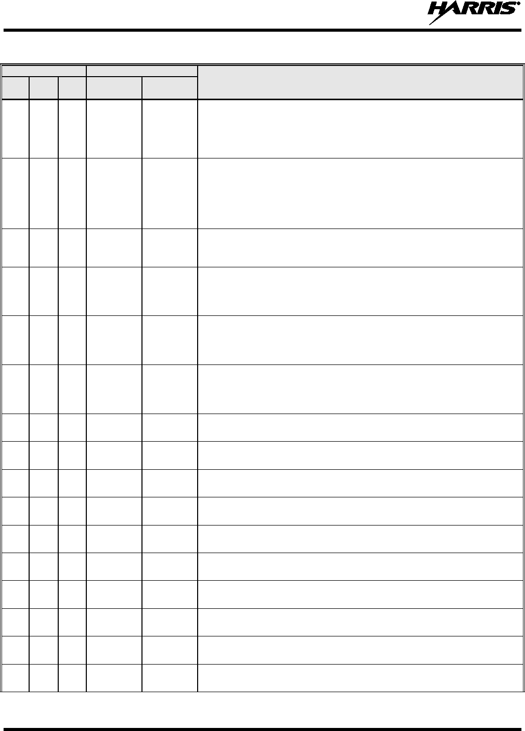
14221-1200-2010
58
Table 9-1: Marine Frequencies
CHANNEL
FREQUENCY
CHANNEL USAGE
US INTL CA
SHIP
(MHZ)
SHORE
(MHZ)
72
72
72
T/R:
156.625
T/R:
156.625
US: Non-Commercial (Intership only)
International: Intership
Canada: May be used to communicate with aircraft and helicopters in
predominantly maritime support operations.
Pleasure craft - British Columbia coast area
73 73 73 T/R:
156.675 T/R:
156.675 US: Port Operations
International: Intership, Port Operations
Canada: May also be used for communications with aircraft engaged in
coordinated search and rescue and antipollution operations. Commercial
fishing only in east coast and inland Manitoba, Saskatchewan, and Alberta
areas.
74
74
74
T/R:
156.725
T/R:
156.725
US: Port Operations
International: Port Operations
Canada: VTS and Ship Movement British Columbia coast area.
75 75 75 T/R:
156.775 T/R:
156.775 International: Port Operations
Canada: Simplex port operation, ship movement and navigation related
communication only.
1 watt maximum.
76 76 76 T/R:
156.825 T/R:
156.825 International: Port Operations
Canada: Simplex port operation, ship movement and navigation related
communication only.
1 watt maximum.
77
77
77
T/R:
156.875
T/R:
156.875
US: Port Operations (Intership only)
International: Intership
Canada: Pilotage -
British Columbia coast area; 25 watts. Port operations only
in the St. Lawrence River/Great Lakes areas with 1 watt maximum power.
78
T: 156.925
R: 161.525
T: 161.525
R: 156.925
International: Public Correspondence, Port Operations
78a 78a T/R:
156.925
T/R:
156.925
US: Non-Commercial
Canada: Fishing Industry - British Columbia coast area.
79 T: 156.975
R: 161.575
T: 161.575
R: 156.975
International: Public Correspondence, Port Operations
79a
79a
T/R:
156.975
T/R:
156.975
US: Commercial. Non-Commercial in Great Lakes only
Canada: Fishing Industry - British Columbia coast area.
80
T: 157.025
R: 161.625
T: 161.625
R: 157.025
International: Public Correspondence, Port Operations
80a
80a
T/R:
157.025
T/R:
157.025
US: Commercial. Non-Commercial in Great Lakes only
Canada: Fishing Industry - British Columbia coast area.
81 T: 157.075
R: 161.675
T: 161.675
R: 157.075
International: Public Correspondence, Port Operations
81a 81a T/R:
157.075
T/R:
157.075
US: US Government only - Environmental protection operations
Canada: DFO/Canadian Coast Guard use only.
82
T: 157.125
R: 161.725
T: 161.725
R: 157.125
International: Public Correspondence, Port Operations
82a
82a
T/R:
157.125
T/R:
157.125
US: US. Government only
Canada: DFO/Canadian Coast Guard use only.
14221-1200-2010
59
Table 9-1: Marine Frequencies
CHANNEL
FREQUENCY
CHANNEL USAGE
US INTL CA
SHIP
(MHZ)
SHORE
(MHZ)
83
T: 157.175
R: 161.775
T: 161.775
R: 157.175
International: Public Correspondence, Port Operations
83a
83a
T/R:
157.175
T/R:
157.175
US: US Coast Guard only
Canada: DFO/Canadian Coast Guard and other Government agencies.
83b - - T/R:
161.775
84
84
84
T: 157.225
R: 161.825
T: 161.825
R: 157.225
US: Public Correspondence (Marine Operator)
International: Public Correspondence, Port Operations
85
85
85
T: 157.275
R: 161.875
T: 161.875
R: 157.275
US: Public Correspondence (Marine Operator)
International: Public Correspondence, Port Operations
86
86
86
T: 157.325
R: 161.925
T: 161.925
R: 157.325
US: Public Correspondence (Marine Operator)
International: Public Correspondence, Port Operations
87 87 87 T: 157.375
R: 161.975 T: 161.975
R: 157.375 US: Automatic Identification System duplex repeater
International: Port Operations
Canada: Port operation and ship movement - east coast area.
Pleasure craft - British Columbia coast area.
87a
T/R:
157.375
T/R:
157.375
US: Public Correspondence (Marine Operator)
87b T/R:
161.975
T/R:
161.975
Canada: Automatic Ship Identification and Surveillance System.
88 88 T: 157.425
R: 162.025 T: 162.025
R: 157.425 US: Commercial, Intership only.
International: Port Operations
Canada: Port operation and ship movement - British Columbia coast area.
88a
T/R:
157.425
T/R:
157.425
US: Commercial, Intership only.
Canada: Automatic Ship Identification and Surveillance System.
88b T/R:
162.025
T/R:
162.025
WX1
WX1
R: 162.55
WX2
WX2
R: 162.4
WX3
WX3
R: 162.475
WX4
R: 162.425
WX5
R: 162.45
WX6
R: 162.5
WX7
R: 162.525

14221-1200-2010
60
9.2 ACCESSORIES
Only use Harris approved accessories. Contact Harris for requirements not contained in this list:
Standard Remote Speaker Microphone (RSM) - Rugged, submersible, 6 ft. (stretch length) coil cord,
swivel clip, 3.5 mm earpiece interface, high/low volume control.
Belt Clip - Supports carrying of the XG-100M on a belt.
1-Bay Charger - Multi-chemistry battery charger, supports radio operation while charging.
6-Bay Charger - Multi-chemistry, multi-bay battery charge, 12 VDC.
Leather Carry Cases - Durable radio carry-cases selectable with swivel D-clip belt-loops or T-straps.
Various styles available.
Nylon Carry Cases - Nylon radio carry cases available in various styles and configurations.
USB Cable - USB computer interface cable for use with RPM and for Key Loading using Harris Key
Loader for the XG-100M.
KVL Cable - Adapter cable supports loading encryption keys with the Motorola KVL 3000 Plus.
AA Clamshell - Battery pack for use with AA-sized batteries.
Lithium Battery - Rechargeable Lithium-ION (Li-ION) battery pack (12082-0308-01).
Antenna - Full-Spectrum, 136-870 MHz frequency coverage.

14221-1200-2010
61
10. GLOSSARY
-A-
AES Advanced Encryption Standard
AES-256 Advanced Encryption Standard, 256-bit
AMBE+2 Advanced Multi-Band Excitation implementation 2
ANSI American National Standards Institute
ASCII American Standard Code for Information Interchange
-B-
-C-
C Celsius
CA Canada
CDCSS Continuous Digital Coded Squelch System
CH INFO Channel Information
CKR Common Key References
CMB Continuous Marine Broadcast
CTCSS Continuous Tone Coded Squelch System
-D-
DES Digital Encryption Standard
DES-OFB Digital Encryption Standard Output Feedback
DFO Department Fisheries Ocean
DMS Degrees Minutes Seconds
-E-
EPIRB Emergency Position-Indicating Radio Beacons
-F-
F Fahrenheit
FCC Federal Communications Commission
FM Frequency Modulation
-G-
GHz Giga (109) Hertz
GEOTRANS Geographic Translator
GPS Global Positioning System
-H-
Hz Hertz
HKL Harris Key Loader
-I-
ID Identification
IEEE Institute of Electrical & Electronics Engineers
INTL International
-J-

14221-1200-2010
62
-K-
KEK Key Encryption Key
kHz kilo (103) Hertz
KID Key Identification
KMF Key Management Facility
KMS Key Management System
KS Key Set
KVL Key Variable Loader (Motorola KVL 3000 Plus)
-L-
LAT/LONG DMS Latitude/Longitude Degrees Minutes Seconds
LED Light Emitting Diode
Li-ION Lithium-ION
-M-
MHz Megahertz
mm Millimeter
MR Mobile Radio
ms milli (10-3) seconds
-N-
NAC Network Access Code
Ni-MH Nickel Metal Hydride
NOAA National Oceanic and Atmospheric Administration
-O-
OET Office of Engineering and Technology
OTAR Over The Air Rekey
-P-
P25 Project 25
POS Position
PRI Priority (Channel)
PTT Push-to-Talk
-Q-
-R-
RF Radio Frequency
RPM Radio Personality Manager
RSI Radio Set Identifier
RSM Remote Speaker Microphone
RX Receive
-S-
SMA Subminiature version A
-T-
TIA Telecommunications Industry Association
TX Transmit

14221-1200-2010
63
-U-
UHF Ultra High Frequency
UKEK Unique Key Encryption Key
US United States
USCG United States Coast Guard
UTC Universal Time Coordinated
UTM Universal Transverse Mercator
-V-
VDC Volts, Direct Current
VHF Very High Frequency
VTS Vessel Traffic Service
-W-
WEEE Waste from Electric and Electronic Equipment
-X-
-Y-
-Z-
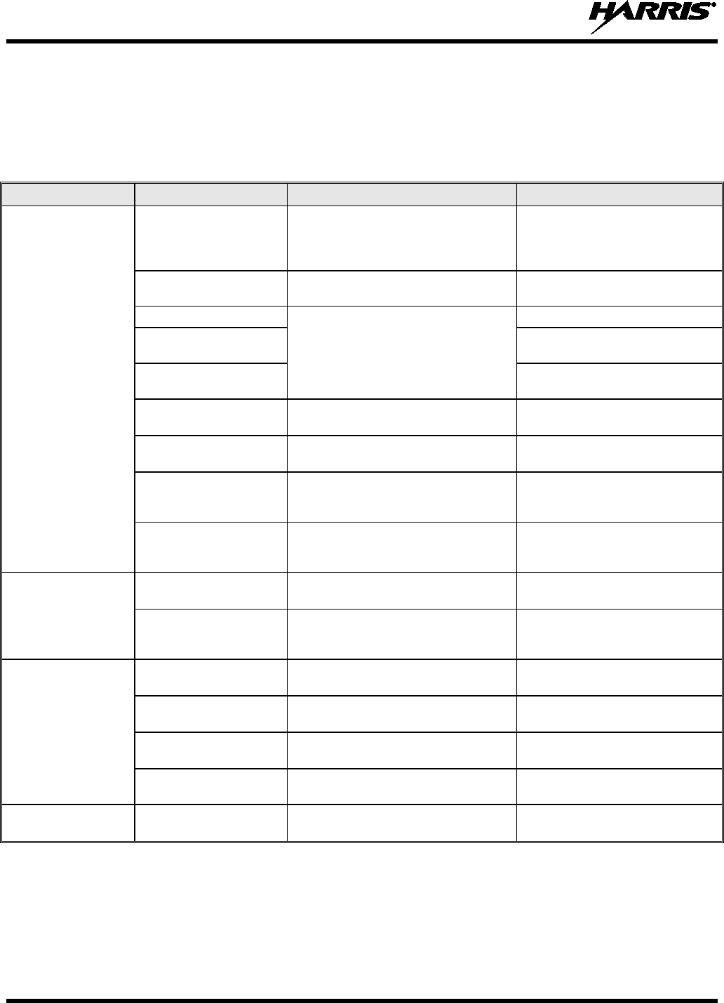
14221-1200-2010
64
11. BASIC TROUBLESHOOTING
11.1 ERROR MESSAGES
This section provides a list of error messages, as well as possible causes and solutions.
SCREEN TEXT REASON RESOLUTION
Top Level Display
DELETE NOT
ALLOWED Nuisance delete not allowed on
current channel.
Requires new personality
configuration (either
Limited/Programmable scan lists
or Keypad P1/P2 channels).
EMERGENCY ACTIVE
SCAN DISABLED Cannot scan when transmitting an
emergency. Exit emergency to start scanning.
OTAR REKEY FAILED
Self-explanatory
Attempt OTAR operation again.
OTAR ZEROIZE
FAILED Attempt OTAR operation again.
NO OTAR KEK
LOADED Load valid KEK before attempting
OTAR.
INVALID OTAR
KEYSETS OTAR configuration failed because
keysets were improperly configured. Zeroize keys and reload KEK(s)
before attempting OTAR.
INVALID KEYSTORE
ZEROIZE NEEDED Corrupt key database. Zeroize database.
SYNTH OUT OF LOCK DSP synthesizer out of lock. Channel will reselect
automatically to attempt to obtain
synth lock.
SYNTH OUT OF LOCK
POWER CYCLE RADIO DSP synthesizer out of lock - unable
to restore by reselecting channel.
Unable to obtain synthesizer lock.
Power cycle radio and contact
Harris if problem persists.
Bluetooth Pairing
Screen
PAIRING FAILED Bluetooth pairing failed. Ensure device is discoverable
and attempt to re-pair the device.
PIN CODE MUST
HAVE AT LEAST 4
DIGITS The PIN entered is too short. Enter at least four digits.
Channel Edit Screen
EDIT FAILED Unable to modify P25 Channel Power cycle and try again--
contact Harris if problem persists
INVALID RX
FREQUENCY Entered Rx frequency is invalid. Ensure frequency follows band
spacing rules.
INVALID TX
FREQUENCY Entered Tx frequency is invalid. Ensure frequency follows band
spacing rules.
INVALID CODE Code entered is not a valid CDCSS
code. Ensure code is valid.
Mission Plan List
Screen EMERGENCY ACTIVE
FILL DISABLED Cannot activate mission plans when
transmitting an emergency. Exit emergency to activate a new
mission plan.
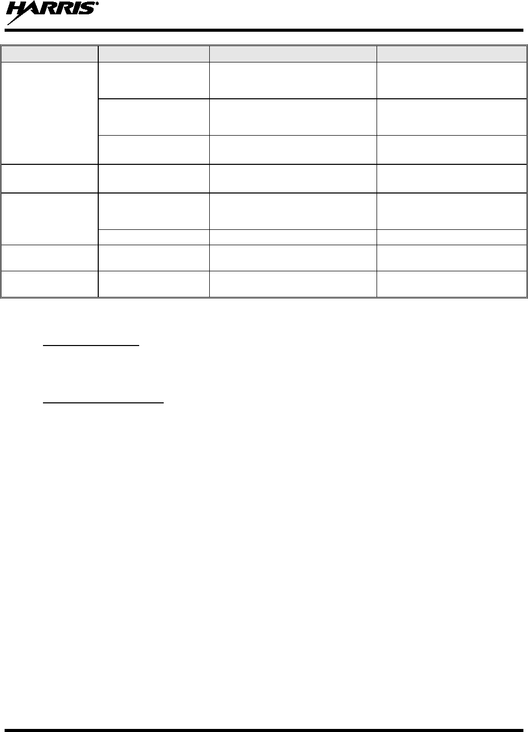
14221-1200-2010
65
SCREEN TEXT REASON RESOLUTION
Install Operations
INSTALL NOT
ALLOWED Error during install process. Transfer the file again and
reattempt install. Contact Harris if
problem persists.
EXTRACTION FAILED Extraction of compressed file failed. Transfer file again and reattempt
install. Contact Harris if problem
persists
REMOVE FAILED Removal of existing software failed Attempt to install again and
contact Harris if problem persists.
Mission Plan In
Progress Screen PLAN FAILED Mission plan activation failed. Use RPM to ensure plan validity.
Contact Harris if failures persist.
Security Menu ZEROIZE FAILED DSP could not zeroize DSP problem — power cycle the
radio and contact Harris if
problem persists.
NO KEYS TO ZEROIZE Key database empty. Nothing to zeroize.
Utilities Menu INCORRECT
PASSWORD Maintenance password invalid. Enter a valid maintenance
password.
Channel Info Screen INCORRECT
PASSWORD Channel edit password invalid. Enter valid channel edit
password.
11.2 OTAR ERRORS/INFORMATION
WORKAROUNDS:
1. Zeroize.
2. Load proper KEK from the Motorola KVL or Harris UKEK Loader.
IF RADIO INDICATES:
1. INVALID KEYSTORE ZEROIZE NEEDED:
This occurs if the radio’s keys were loaded by the Harris Key Loader followed by an attempt to load
UKEKs with the UKEK Loader or keys with the Motorola KVL. Fix by performing workaround 1,
followed by 2.
2. NO UKEK – Displayed during a zeroize performed from the radio or a zeroize initiated from the
KMF.
- Fix by performing workaround 2.
3. Zeroize Complete – KMF has zeroized the radio.
- Fix by performing workaround 2.
4. Disabled OTAR Icon (red slash) – OTAR is disabled while in scan, talkaround, emergency, and
monitor.
- Fix by disabling these features. Icon will be corrected (no red slash).
5. Gray OTAR Icon (no red slash) – OTAR has not registered with tower (Conventional or Trunked
system).
- Fix by verifying proper frequencies.
- If the radio is turned to the OTAR channel out of range of a conventional tower, and then comes
in range after 3 minutes, fix by issuing an OTAR. Rekey, leaving and re-enter the OTAR channel.

14221-1200-2010
66
6. Green OTAR Icon – OTAR is registered, all is well.
- If update fails, verify you are in range of the tower and the KEK is correct.
7. Blue OTAR Icon – OTAR is attempting to rekey.
- If rekey fails, verify you are in range of the tower and the KEK is correct.

14221-1200-2010
67
12. TECHNICAL ASSISTANCE
The Technical Assistance Center's (TAC) resources are available to help with overall system operation,
maintenance, upgrades and product support. TAC is the point of contact when answers are needed to
technical questions.
Product specialists, with detailed knowledge of product operation, maintenance and repair provide
technical support via a toll-free (in North America) telephone number. Support is also available through
mail, fax and e-mail.
For more information about technical assistance services, contact your sales representative, or contact the
Technical Assistance Center directly at:
North America: 1-800-528-7711
International: 1-434-385-2400
Fax: 1-434-455-6712
E-mail: PSPC_tac@harris.com

14221-1200-2010
68
13. WARRANTY
Please register this product within 10 days of purchase. Registration validates the warranty coverage, and enables Harris to contact
you in case of any safety notifications issued for this product.
Registration can be made on-line at www.pspc.harris.com/CustomerService or by contacting Harris Warranty Administration at the
following:
U.S. & Canada
Phone Number: 1-800-368-3277, Option 4 (toll free)
:
Fax Number: 1-434-455-6821
E-mail: mailto:WarrantyClaims@Harris.com
International:
Phone Number: 1-434-455-6403
Fax Number: 1-434-455-6676
E-mail: mailto:WarrantyClaims@Harris.com
A. Harris Corporation, a Delaware Corporation, through its RF Communications Division (hereinafter "Seller") warrants to the
original purchaser for use (hereinafter "Buyer") that Equipment manufactured by or for the Seller shall be free from defects in
material and workmanship, and shall conform to its published specifications. With respect to all non-Seller Equipment, Seller
gives no warranty, and only the warranty, if any, given by the manufacturer shall apply. Rechargeable batteries are excluded
from this warranty but are warranted under a separate Rechargeable Battery Warranty (ECR-7048).
B. Seller’s obligations set forth in Paragraph C below shall apply only to failures to meet the above warranties occurring within the
following periods of time from date of sale to the Buyer and are conditioned on Buyer’s giving written notice to Seller within thirty
(30) days of such occurrence:
1. for fuses and non-rechargeable batteries, operable on arrival only.
1. for parts and accessories (except as noted in B.1), ninety (90) days.
2. for P7300, P7200, P7100IP, P5400, P5300, P5200, P5100, P3300, M7300, M7200
(including V-TAC), M7100IP, M5300 and M3300 radios, two (2) years, effective 10/01/2007.
3. for Unity® XG-100M, three (3) years.
5. for all other equipment of Seller’s manufacture, one (1) year.
C. If any Equipment fails to meet the foregoing warranties, Seller shall correct the failure at its option (i) by repairing any defective or
damaged part or parts thereof, (ii) by making available at Seller’s factory any necessary repaired or replacement parts, or (iii) by
replacing the failed Equipment with equivalent new or refurbished Equipment. Any repaired or replacement part furnished
hereunder shall be warranted for the remainder of the warranty period of the Equipment in which it is installed. Where such
failure cannot be corrected by Seller’s reasonable efforts, the parties will negotiate an equitable adjustment in price. Labor to
perform warranty service will be provided at no charge during the warranty period only for the Equipment covered under
Paragraph B.3 and B.4. To be eligible for no-charge labor, service must be performed at Seller’s factory, by an Authorized
Service Center (ASC) or other Servicer approved for these purposes either at its place of business during normal business hours,
for mobile or personal equipment, or at the Buyer’s location, for fixed location equipment. Service on fixed location equipment
more than thirty (30) miles from the Service Center or other approved Servicer’s place of business will include a charge for
transportation.
D. Seller’s obligations under Paragraph C shall not apply to any Equipment, or part thereof, which (i) has been modified or otherwise
altered other than pursuant to Seller’s written instructions or written approval or, (ii) is normally consumed in operation or, (iii) has
a normal life inherently shorter than the warranty periods specified in Paragraph B, or (iv) is not properly stored, installed, used,
maintained or repaired, or, (v) has been subjected to any other kind of misuse or detrimental exposure, or has been involved in
an accident.
E. The preceding paragraphs set forth the exclusive remedies for claims based upon defects in or nonconformity of the Equipment,
whether the claim is in contract, warranty, tort (including negligence), strict liability or otherwise, and however instituted. Upon the
expiration of the warranty period, all such liability shall terminate. The foregoing warranties are exclusive and in lieu of all other
warranties, whether oral, written, expressed, implied or statutory. NO IMPLIED OR STATUTORY WARRANTIES OF
MERCHANTABILITY OR FITNESS FOR PARTICULAR PURPOSE SHALL APPLY. IN NO EVENT SHALL THE SELLER BE
LIABLE FOR ANY INCIDENTAL, CONSEQUENTIAL, SPECIAL, INDIRECT OR EXEMPLARY DAMAGES.
This warranty applies only within the United States.
Harris Corporation Harris Corporation
RF Communications Division RF Communications Division
221 Jefferson Ridge Parkway 1680 University Avenue
Lynchburg, VA 24501 Rochester, NY 14610
1-800-528-7711 1-585-244-5830
ECR-7047L