Harris RF Communications Division XG-100M00 Unity MultiBand Mobile User Manual Manual 2
Harris Corporation RF Communications Division Unity MultiBand Mobile Manual 2
UserManual.wiki
>
Harris RF Communications Division
>
XG-100M00 User Manual
>
Manual 2
Contents
1.
Manual 1
2.
Manual 2
3.
Manual 3
4.
manual 1
5.
manual 2
6.
manual 3
7.
User Manual 1
8.
User Manual 2
Manual 2
Navigation menu
Upload a User Manual
Namespaces
Wiki Guide
HTML
PDF
Info
Views
User Manual
Discussion / Help
Navigation
![14221-1200-2010 13 5. INTRODUCTION Your XG-100M provides full-spectrum multiband coverage: • 30 to 50 MHz, VHF Low (Transmit requires external power amplifier) • 136 to 174 MHz, VHF High (5 – 50 W) • 380 to 520 MHz, UHF-Low, UHF-High (5 – 50 W) • 762 to 805 MHz, 700 MHz (2 – 30 W) • 805 to 870 MHz, 800 MHz (2 – 35 W) The XG-100M has the following capabilities: • Project 25 (P25) Conventional • P25 Trunking • Analog FM • Advanced Encryption Standard, 256-bit (AES-256) • Digital Encryption Standard Output Feedback (DES-OFB) Encryption • Digital Encryption Standard Cipher Feedback (DES-CFB) Encryption • Global Positioning System (GPS) • Bluetooth® • Over The Air Rekey (OTAR) • Preemptive Priority Scanning • Global Common Key References (CKR) • Feature Management (Using Radio Personality Manager [RPM] R6A or later) For optional accessories, refer to Section 9.2. Additional accessories may have been added since publication of this manual; contact Harris for more information.](https://usermanual.wiki/Harris-RF-Communications-Division/XG-100M00.Manual-2/User-Guide-1470306-Page-13.png)
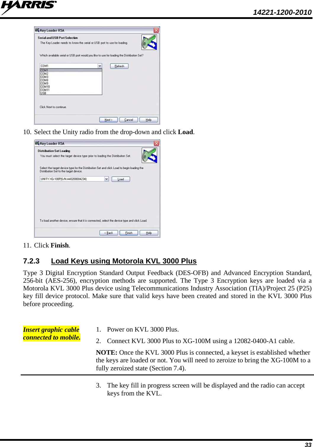
![14221-1200-2010 31 NOTE The XG-100 does not support KID 0000. Attempting to load a key with KID 0000 from the KVL will result in the failure UNKNOWN ERRICHECK TARGETALGORITHM! displayed on the KVL. KID 0000 is reserved for the Suppressed Key feature. 8. Enter a hexadecimal number as the Key value. DES-OFB keys are 16 digits while AES keys are 64 digits (32 bytes [256 bits]). Odd parity checks are made between every two digits for DES-OFB keys. Parity checks are not made for AES-256 keys. 9. KVL 3000 Plus will display SLOT FILLED, press ENTER. 10. A message is displayed when complete: KEY WAS CREATED SUCCESSFULLY. 11. Refer to Section 7.2 for loading a key into the radio. 7.1.3 Create Keygroup in the KVL 3000 Plus You can generate a group of Type-3 keys in the KVL 3000 Plus: 1. Turn on the KVL 3000 Plus. 2. Select Esc. 3. Select GROUPS. 4. Select NEW. 5. Enter a Group Name (up to seven characters). 6. Select CKRs from the programmed list until all desired CKRs are selected. 7. Select DONE. Refer to Section 7.2 for loading a keyset into the radio. 7.2 LOAD KEYS 7.2.1.1 Load UKEKs with UKEK Loader and RPM (for OTAR -E nabled S ys tems ) UKEKs are loaded into Harris OTAR radios using the UKEK Loader application. UKEK Loader is a part of Key Manager. To load encryption keys: 1. Obtain the UKEK file and Storage Location Number (SLN) Binding Report information from the Crypto Officer (CO). NOTE Both AES and DES UKEKs can be contained within the same UKEK file 2. If not already on, power-up the PC that has RPM and the UKEK Loader applications installed on it, and start Windows. 3. Connect the radio to the PC using programming cable 12082-0410-A1. NOTE The Unity drivers must be installed before UKEKs can be loaded into the radio. The Unity drivers may be found on the Key Loader CD (“unity setup.exe”) or on the Key Admin CD (“unity setup.exe”).](https://usermanual.wiki/Harris-RF-Communications-Division/XG-100M00.Manual-2/User-Guide-1470306-Page-31.png)