Harris RF Communications Division XG-100M00 Unity MultiBand Mobile User Manual manual 1
Harris Corporation RF Communications Division Unity MultiBand Mobile manual 1
UserManual.wiki
>
Harris RF Communications Division
>
XG-100M00 User Manual
>
manual 1
Contents
1.
Manual 1
2.
Manual 2
3.
Manual 3
4.
manual 1
5.
manual 2
6.
manual 3
7.
User Manual 1
8.
User Manual 2
manual 1
Navigation menu
Upload a User Manual
Namespaces
Wiki Guide
HTML
PDF
Info
Views
User Manual
Discussion / Help
Navigation
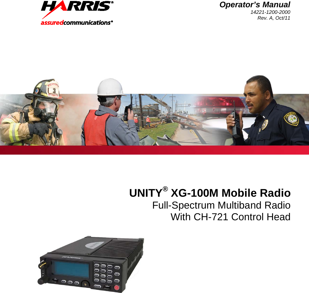
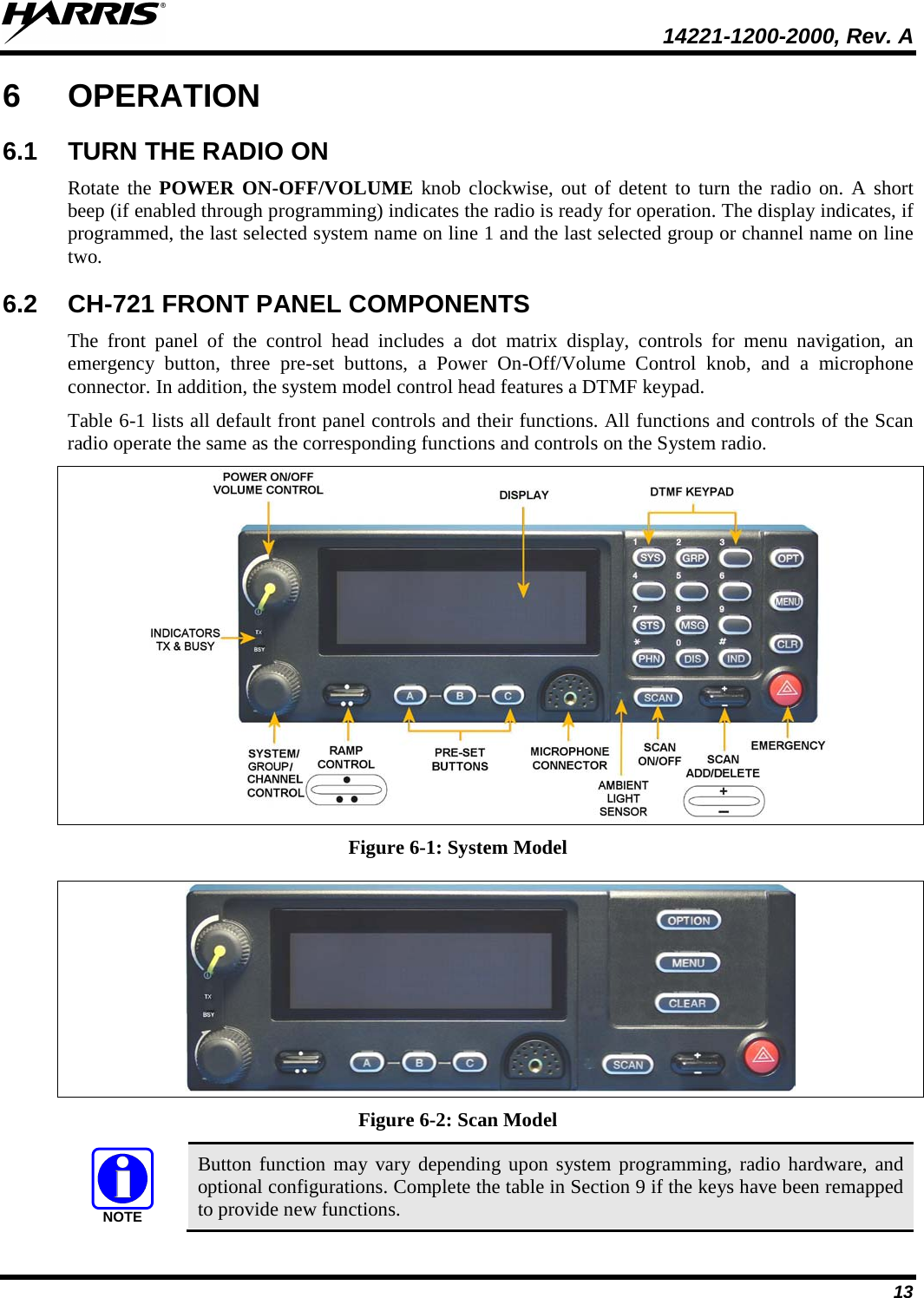
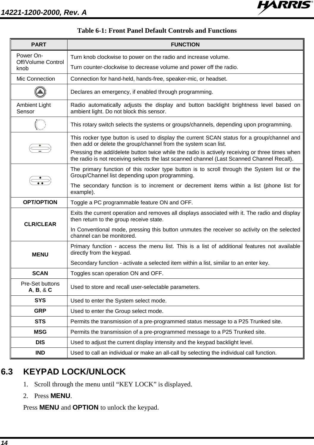
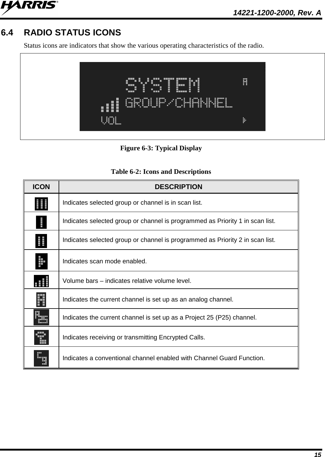
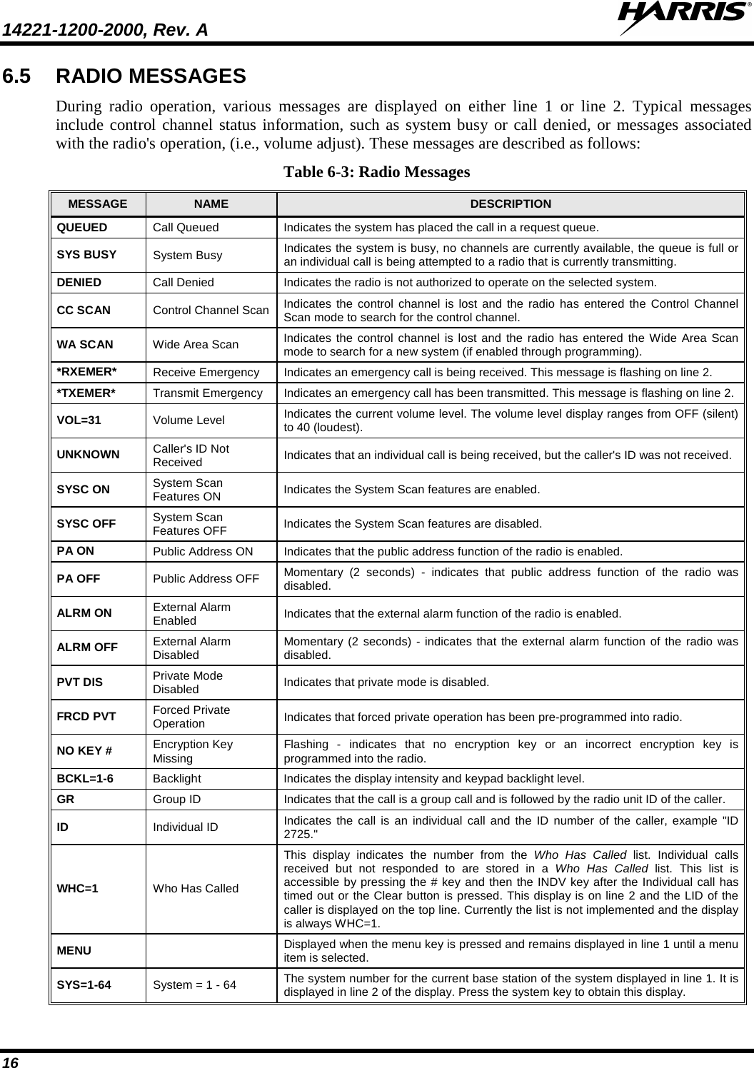
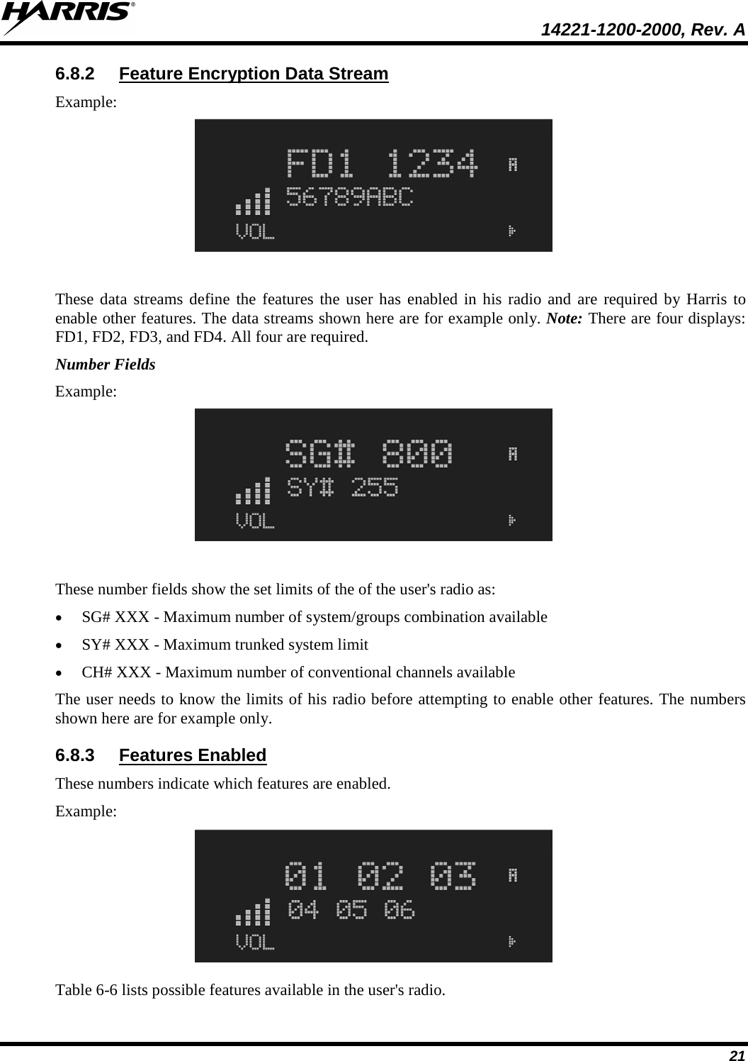
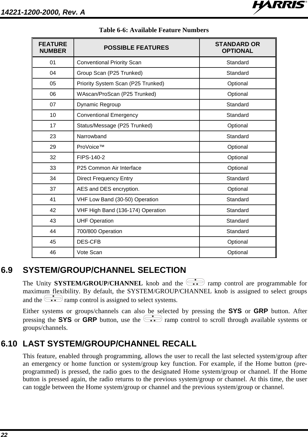
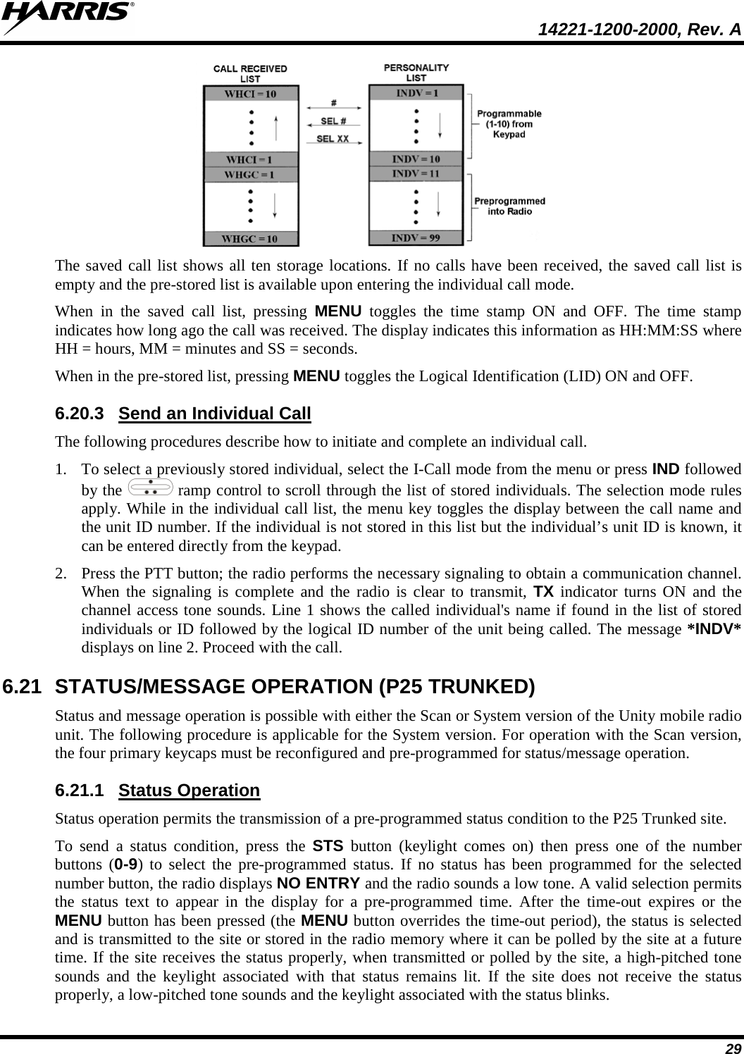
![14221-1200-2000, Rev. A 12 5 PRODUCT DESCRIPTION The Unity mobile is a state-of-the-art radio designed to meet the critical demands of its users. The XG-100M provides full-spectrum multiband coverage: • 30 to 50 MHz, VHF Low (Receive Only) • 136 to 174 MHz, VHF High (5 – 50 W) • 380 to 520 MHz, UHF-Low, UHF-High (5 – 50 W) • 762 to 805 MHz, 700 MHz (2 – 30 W) • 805 to 870 MHz, 800 MHz (2 – 35 W) The XG-100M has the following capabilities: • Project 25 (P25) Conventional • P25 Trunking • Analog FM • Advanced Encryption Standard, 256-bit (AES-256) • Digital Encryption Standard Output Feedback (DES-OFB) Encryption • Digital Encryption Standard Cipher Feedback (DES-CFB) Encryption • Global Positioning System (GPS) • P25 Trunking Over The Air Rekey (OTAR) • Preemptive Priority Scanning • Feature Management (Using Radio Personality Manager [RPM] R7A or later) The XG-100M mobile radio supports the CH-721 Control Head which is available in System and Scan models. The display is designed to maximize readability and ease of use. The CH-721 utilizes a 3-line 12-character alphanumeric display with large buttons, volume knob, and channel knob, providing a user-friendly interface. For remote mount installations configured with a CH-721 control head, all normal radio operations and interfaces can be handled via the control head connected to the radio unit via a 3-wire Controller Area Network (CAN) cable. Two CH-721 control heads may be attached to the XG-100M. Each control head provides a serial access point for data and any one (only one at a time) can be connected to a data device such as a personal computer. Where multiple control heads are connected or where a dash-mount radio is installed with an additional remote control head, the following features are available from both positions: • Either control head can initiate a call but only one can talk at a time. The other connected control head hears both sides of the conversation. • Incoming and outgoing audio can be heard. • Independent audio control is available. • Radio settings such as talk group, scan mode etc., can be controlled by either control head. • Comfort settings, such as volume and display brightness that are applicable to the individual control head can be adjusted and cannot be overridden by the other control head.](https://usermanual.wiki/Harris-RF-Communications-Division/XG-100M00.manual-1/User-Guide-1566530-Page-12.png)