Harris RF Communications Division XG-100M00 Unity MultiBand Mobile User Manual Manual 1
Harris Corporation RF Communications Division Unity MultiBand Mobile Manual 1
UserManual.wiki
>
Harris RF Communications Division
>
XG-100M00 User Manual
>
Manual 1
Contents
1.
Manual 1
2.
Manual 2
3.
Manual 3
4.
manual 1
5.
manual 2
6.
manual 3
7.
User Manual 1
8.
User Manual 2
Manual 1
Navigation menu
Upload a User Manual
Namespaces
Wiki Guide
HTML
PDF
Info
Views
User Manual
Discussion / Help
Navigation

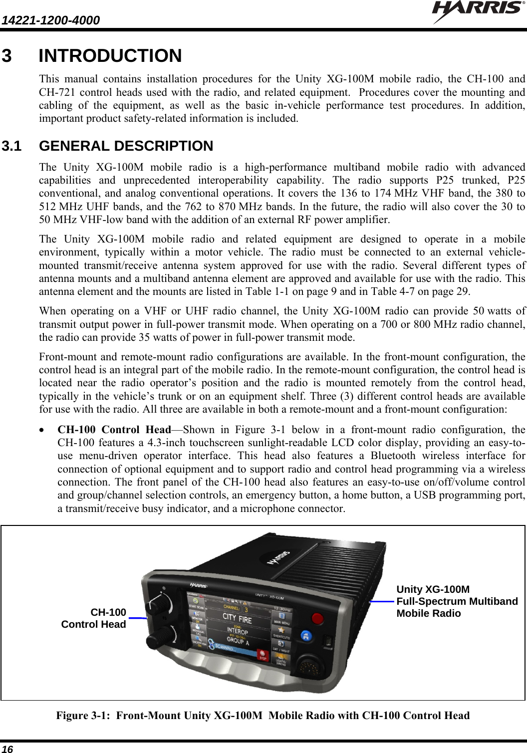
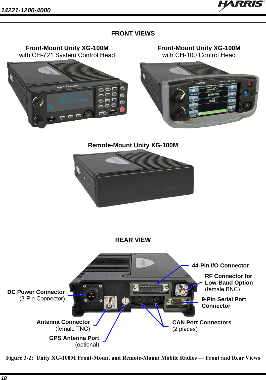
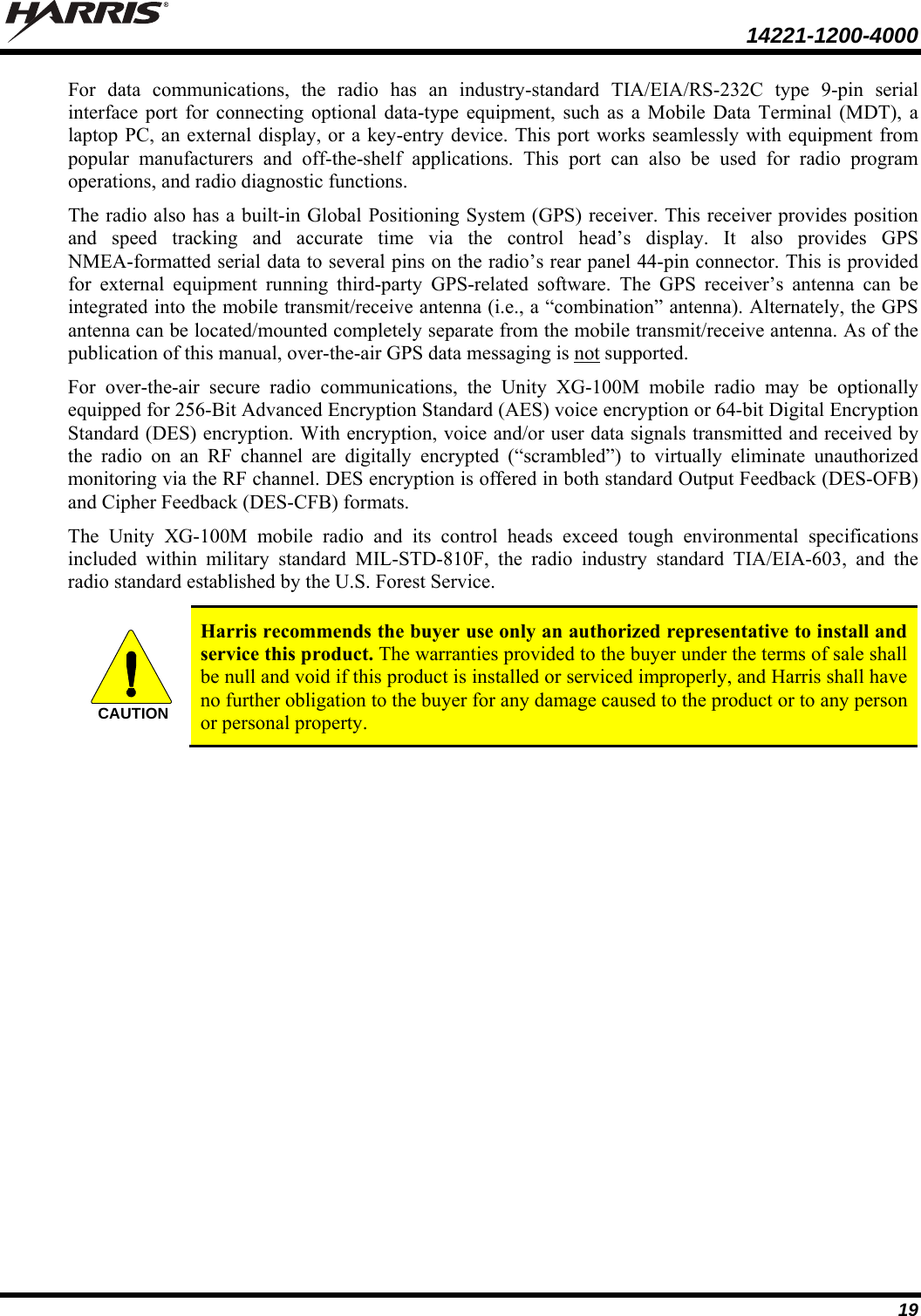
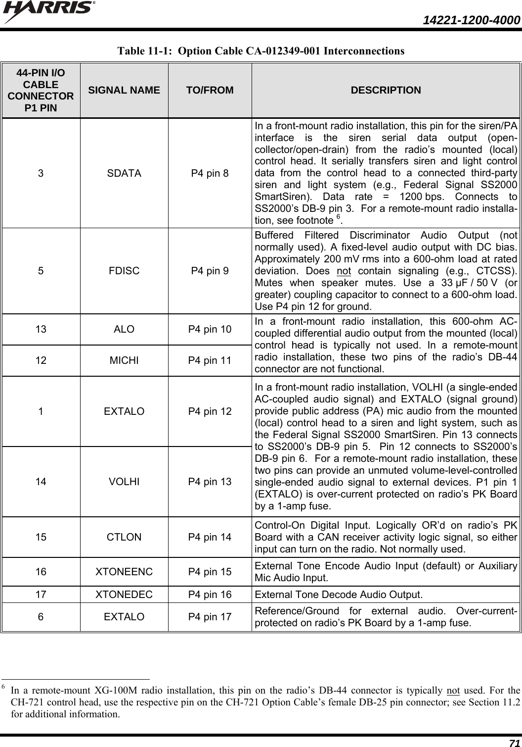
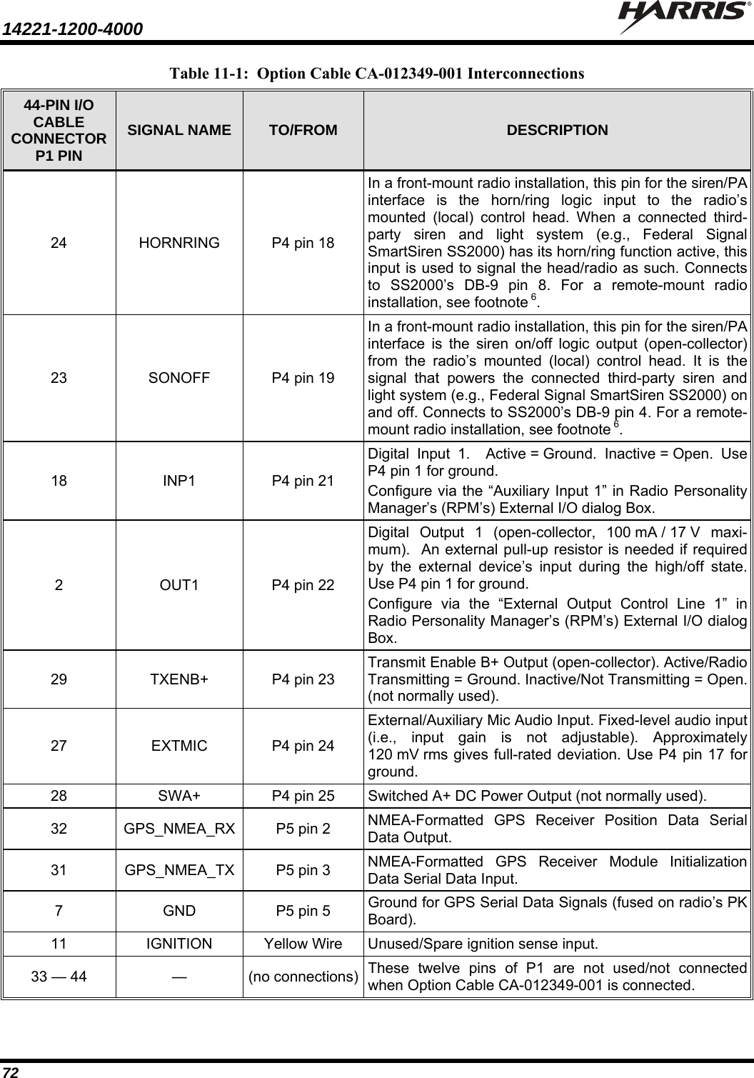
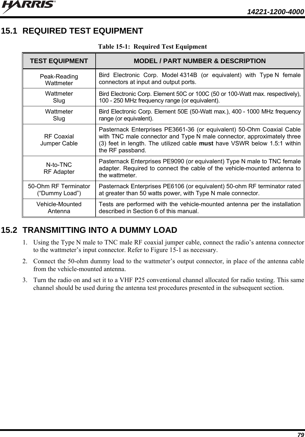
![14221-1200-4000 13 2 SPECIFICATIONS1 2.1 GENERAL Dimensions, Height x Width x Depth (See footnote 2) Front-Mount Radio with CH-100: 3.3 x 7.0 x 11.6 inches (8.4 x 17.8 x 29.5 centimeters) Front-Mount Radio with CH-721: 2.4 x 6.9 x 11.3 inches (6.1 x 17.5 x 28.7 centimeters) Remote-Mount Radio: 2.0 x 6.9 x 9.7 inches (5.1 x 17.5 x 24.7 centimeters) CH-100 Control Head (Remote-Mount): 3.3 x 7.0 x 2.8 inches (8.4 x 17.8 x 7.1 centimeters) CH-721 Control Head (Remote-Mount): 2.4 x 6.9 x 3.9 inches (6 x 17.5 x 10 centimeters) Weight (See footnote 3) Front-Mount Radio: 5.9 pounds (2.68 kilograms) Remote-Mount Radio: 5.25 pounds (2.38 kilograms) Control Head (Remote-Mount): 1.25 pounds (0.57 kilograms) Operating Ambient Temperature Range: -22 to +140° Fahrenheit (-30 to +60° Celsius) Maximum Altitude Operating: 15,000 feet (4,572 meters) In Transit: 40,000 feet (12,192 meters) DC Supply Voltage Operating Ranges For Full Performance: +13.6 Vdc ±10% (Normal range per TIA-603) Overall Operating Range: +10.8 to +16.6 Vdc Continuous without Damage: 0 to +17 Vdc DC Supply Current Requirements Receive (includes control head) With 15-Watt Speaker Output Power: 4.0 amps maximum Transmit (includes control head): At 35 Watts RF: 15 amps maximum, 12 amps typical At 50 Watts RF (VHF and UHF Bands): 20 amps maximum, 15 amps typical Quiescent/Off Currents Mobile Radio Only: 2 milliamps maximum CH-100 Control Head Only: 100 microamps maximum CH-721 Control Head Only: 100 microamps maximum 2.2 TRANSCEIVER 2.2.1 General Frequency Ranges VHF High Band: 136 to 174 MHz UHF Bands: 380 to 520 MHz [See footnote 4] 700 and 800 MHz Bands 762 to 870 MHz [See footnote 5] 1 These specifications are primarily intended for the use of the installation technician. See the appropriate Specifications Sheet for the complete specifications. 2 Dimensions do not space required for mounting brackets, cables, clearance/access, etc. 3 Weights do not include respective mounting brackets, cables, etc. 4 Per FCC regulations, the lowest allowed UHF band transmit frequency for LMR operations is 406.1 MHz. 5 700 MHz mobile receive band is 764 to 767 MHz and 769 to 776 MHz. 700 MHz mobile transmit band is 764 to 767 MHz, 769 to 776 MHz, 794 to 797 MHz and 799 to 806 MHz.](https://usermanual.wiki/Harris-RF-Communications-Division/XG-100M00.Manual-1/User-Guide-1470305-Page-13.png)