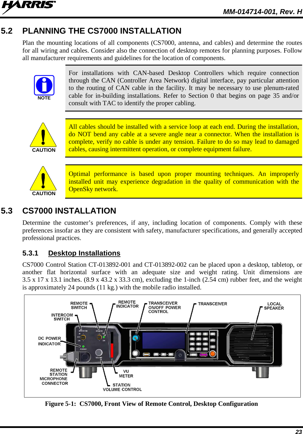
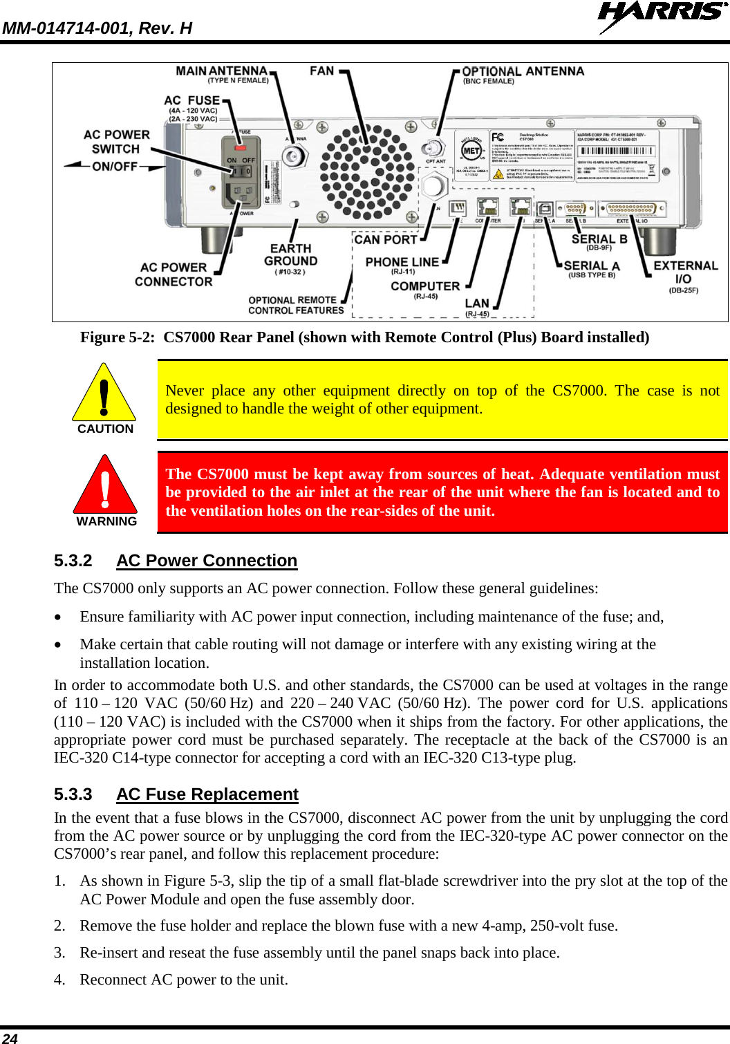
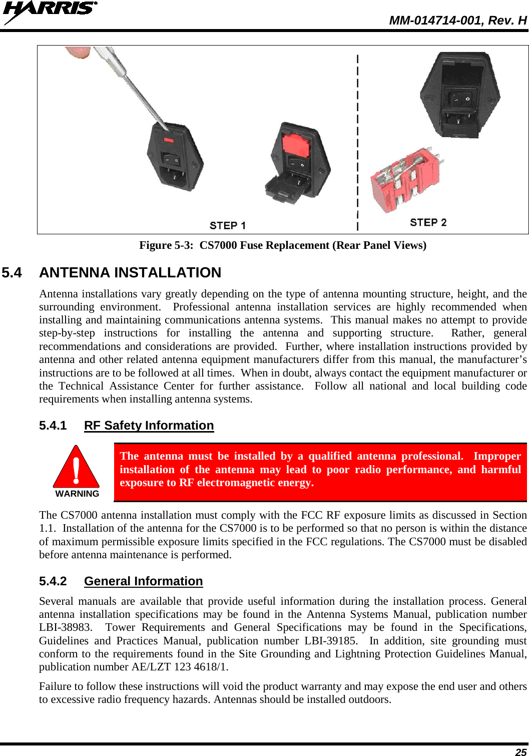
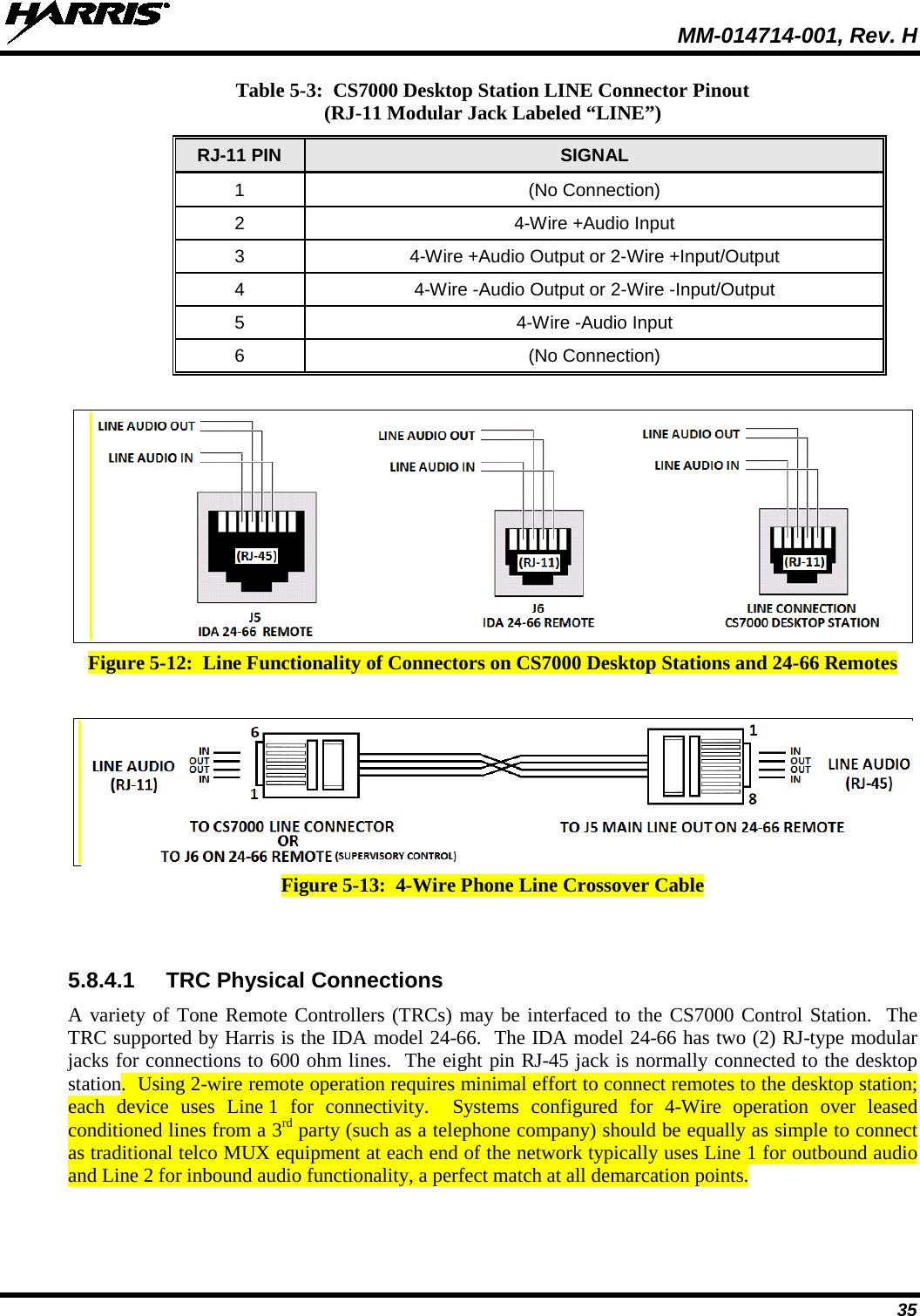
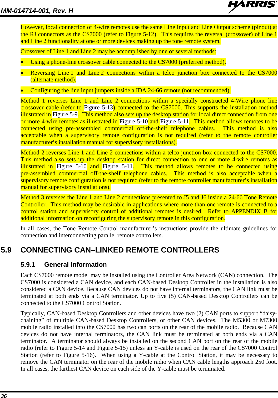
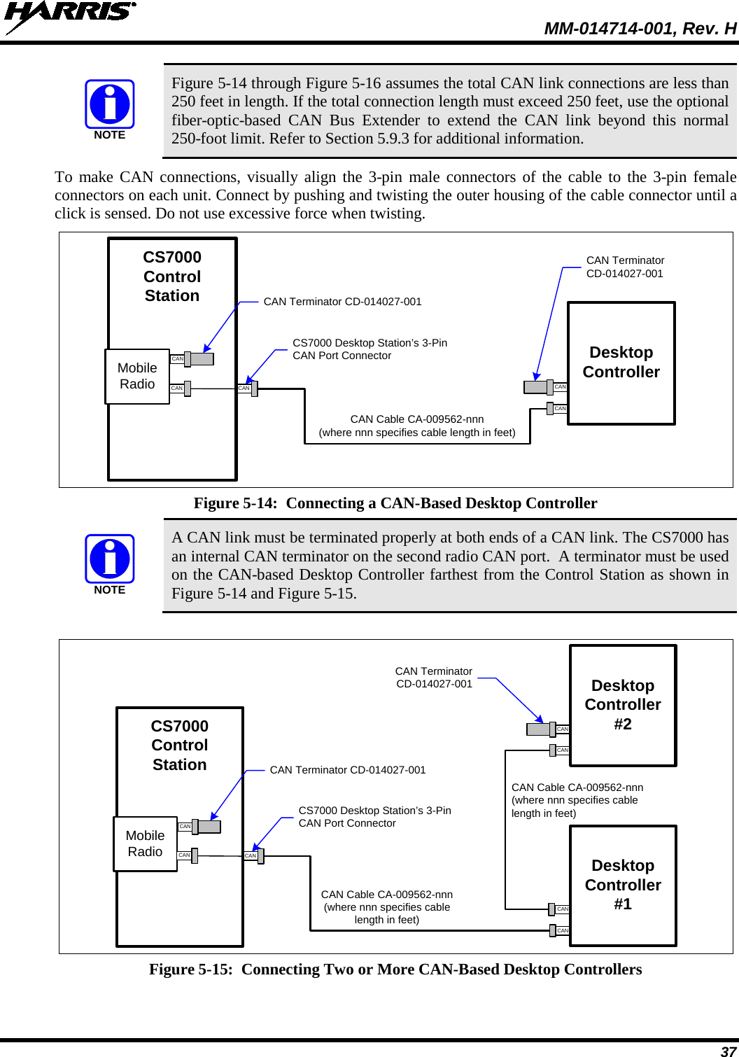
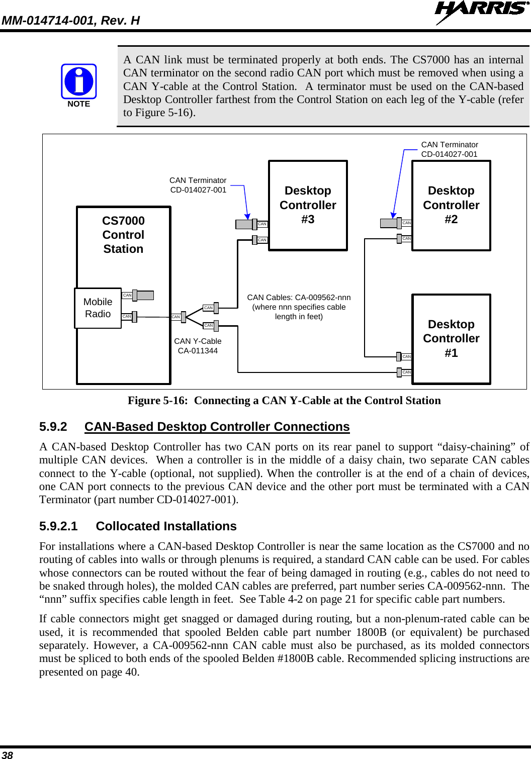
Harris RF Communications Division XG-100M00 Unity Multiband Mobile User Manual MM 014714 001 Rev G CS7000 Control Station
Harris Corporation RF Communications Division Unity Multiband Mobile MM 014714 001 Rev G CS7000 Control Station
Contents
User Manual 2

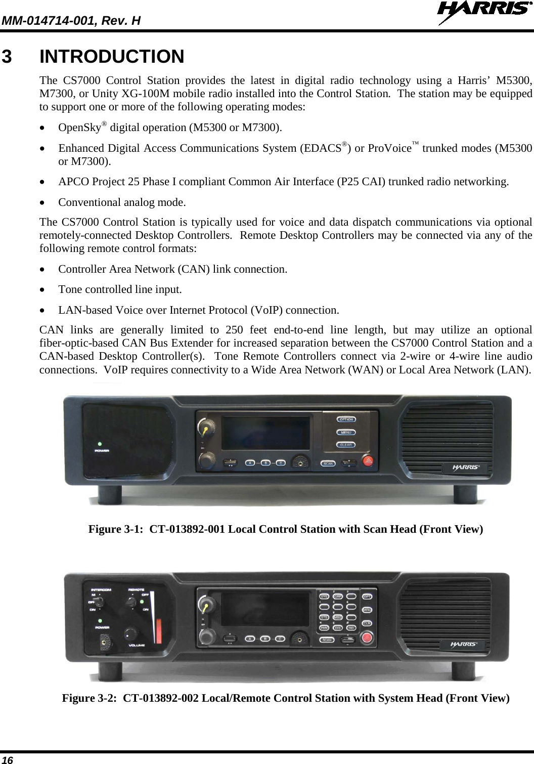
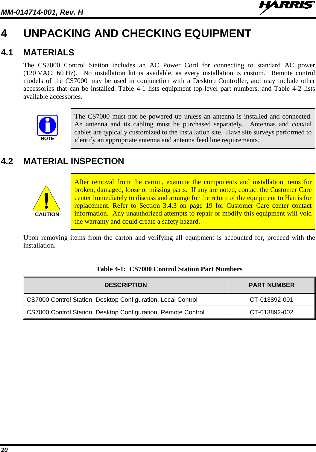
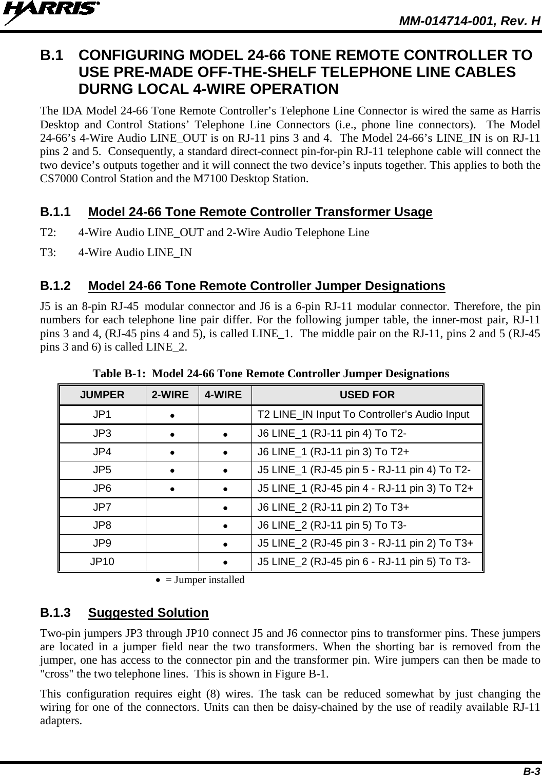
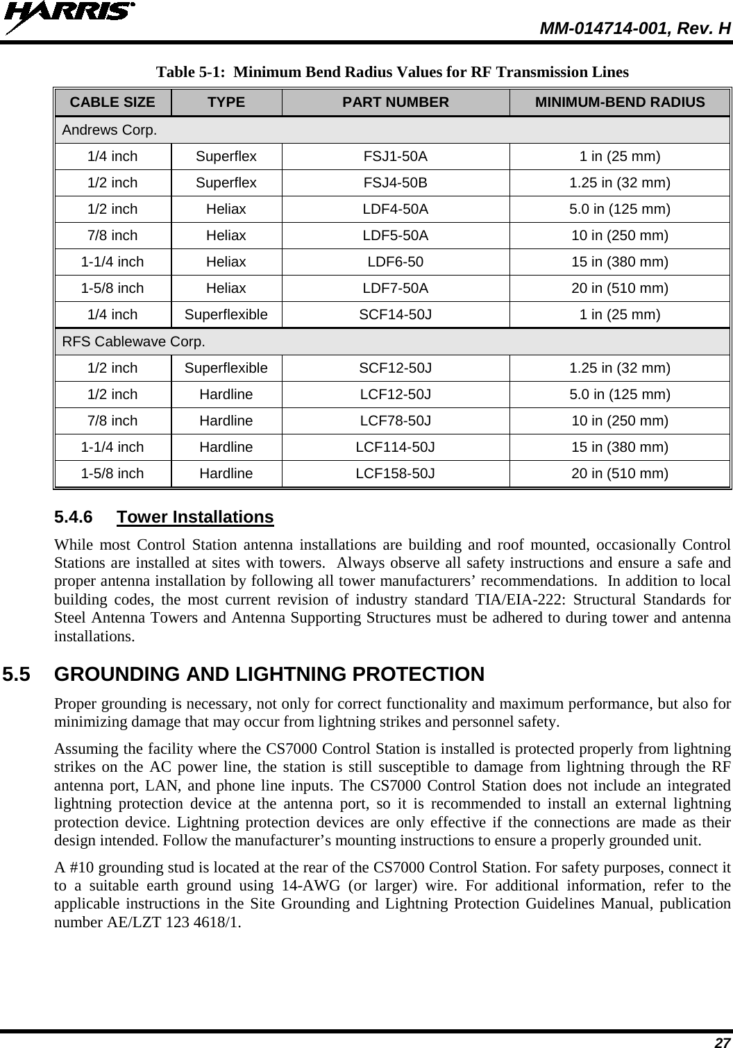
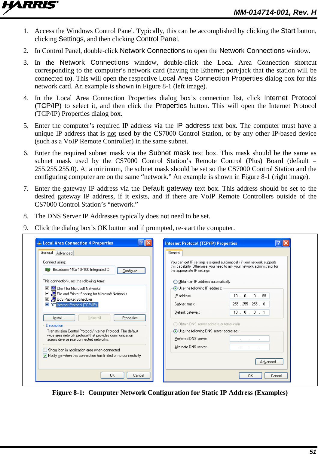
![MM-014714-001, Rev. H 21 Table 4-2: CS7000 Control Station Accessories DESCRIPTION PART NUMBER Desktop Microphone MC-014121-001 Desktop Microphone MC-014121-002 Antenna, 800 MHz Yagi with 10 dBd (12 dBi) Gain AN-025137-008 Cable, Coax: Antenna Jumper Kit MAMROS0095 Lightning Protection Device, DC Blocked, (Sim. to. PolyPhaser: DSXL-MA-BF), 700 to 2700 MHz, N-male (ant.) to N-female (eq.) DSXL-MA-BF CAN Terminator CD-014027-001 Cable, CAN; 0.6 feet, Black, Right-Angle-to-Straight Connectors CA-009562-0R6 Cable, CAN; 6 feet, Black, Right-Angle-to-Straight Connectors CA-009562-006 Cable, CAN; 30 feet, Black, Right-Angle-to-Straight Connectors CA-009562-030 Cable, CAN; 90 feet, Black, Right-Angle-to-Straight Connectors CA-009562-090 Cable, CAN; 250 feet, Black, Right-Angle-to-Straight Connectors CA-009562-250 CAN Y-cable, Black, Right-Angle-to-Two Straight Connectors CA-011344 Kit, CAN Bus Extender (Includes CAN Bus Extender MD-008577 and AC Wall Power Supply) [2 required per optical CAN link] MAA7-NSU5C USB Communications Port Driver Software SK-015121-001 Radio Personality Manager (SK-104768-001: Programming Software for P25, EDACS, OpenSky) TQS3385 Rev. B (minimum) Radio Personality Manager (SK-012177-001: Programming Software for Analog Conventional and P25 Conventional) TQS3389 Rev. A (minimum) Tone Remote Controller: IDA Model 24-66 with Desk Mic (Used with CS7000 Control Station CT-013892-002) ID-431-24-66M Tone Remote Controller: IDA Model 24-66 with Handset (Used with CS7000 Control Station CT-013892-002) ID-431-24-66H VoIP Remote Controller: IDA Model ID-431-24-66M-VOIP, w/Handset (Used with CS7000 Control Station CT-013892-002) CU-017947 VoIP Remote Controller: IDA Model ID-431-24-66H-VOIP, w/ Desk Mic (Used with CS7000 Control Station CT-013892-002) CU-017948 Wall Mount Bracket for IDA 24-66 series remotes 431-RBC-001 Rack Mount Kit for CS7000 HD-014666-001 Headset/Footswitch option for IDA 24-66 series remotes w/Desk Mic 431-RBC-007 CS7000 Fan Upgrade Kit KT-018569-002](https://usermanual.wiki/Harris-RF-Communications-Division/XG-100M00.User-Manual-2/User-Guide-1602941-Page-21.png)
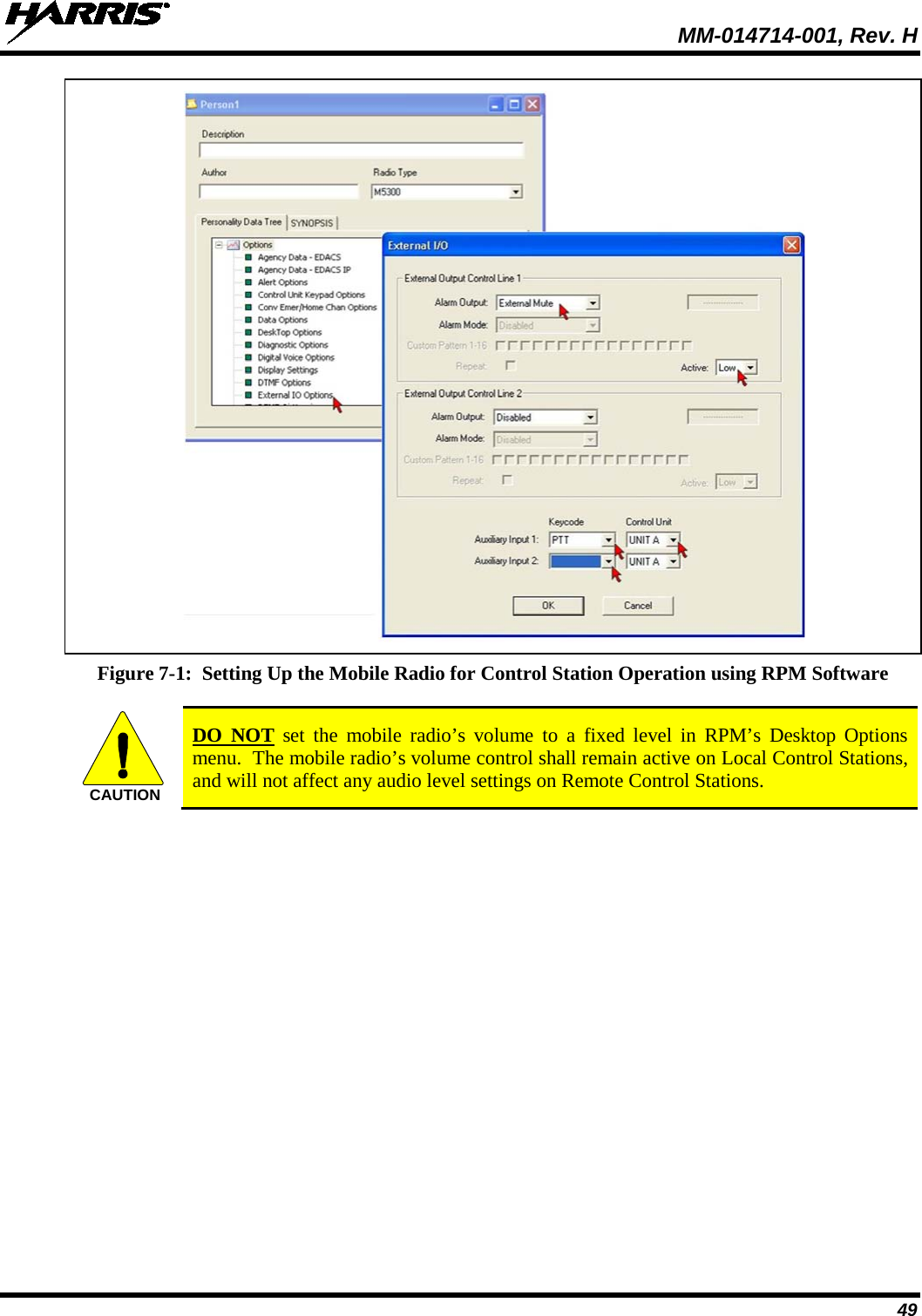
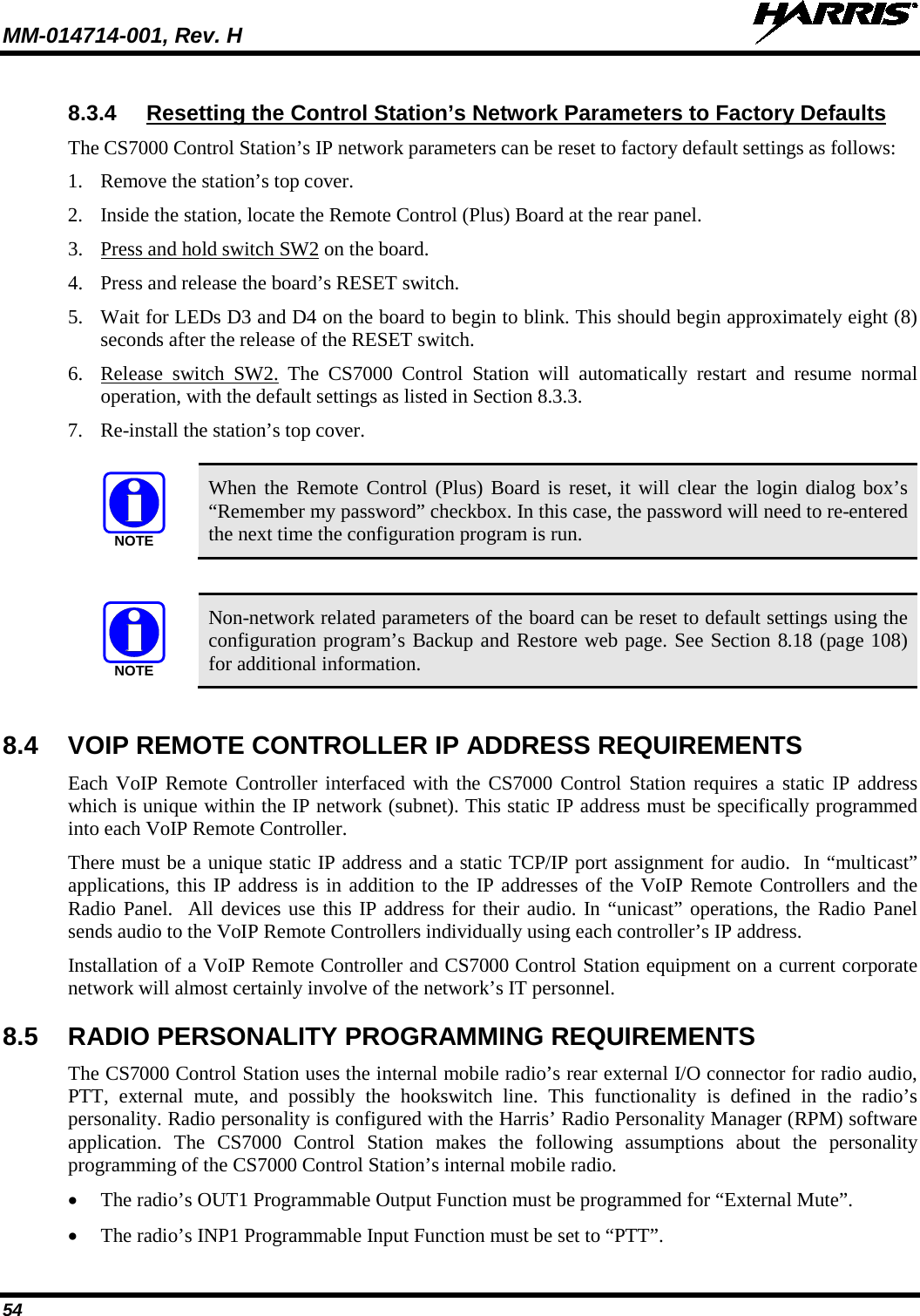

![MM-014714-001, Rev. H 123 3. From RPM’s Personality Data Tree (i.e., in its main dialog box), select Options > System/Group Keys, then using the drop-down menu beside SG16, select the OTP system. 4. From RPM’s Personality Data Tree, select Options > Control Unit Keypad Options, then using the drop-down menu beside Button C, select SG16. 5. Program the revised personality into the radio. 6. Archive the revised personality and close RPM programming software. 7. Cycle power to the radio. Afterward, momentarily press the control head’s Preset C button. Verify the radio toggles from ECP mode to OTP mode. If not, verify/repeat this section’s instructions. 10.2.1.2 OTP Preset C Button Programming Setup If Section 10.2.1.1 is performed, it is imperative that Section 10.2.1.2 is also performed to ensure the ability of switching back and forth between operating modes. The preferred method for changing from OTP mode to ECP mode is through the use of the Preset C button. The following procedure describes how to program the radio for this functionality. OTP software version 19.95 and later support Quick Key functionality. A radio can be switched from OTP mode to ECP mode via the control head’s menu structure (if enabled) or by via DTMF/keypad sequence 1#. After programming the radio per instructions in Section 10.2.1.1, perform the following: 1. From the PC already connected to the CS7000 Desktop Station, run a terminal emulation program such as HyperTerminal. 2. Setup the terminal program’s COM Port to the port assigned to the USB connection. 3. The radio must be in OTP mode to program the Preset C button for use during OTP operation. At this point, there are several ways to accomplish placing the radio in OTP mode: a. If the procedure in Section 10.2.1.1 was previously performed, the radio should now be in OTP mode. If not, press the Preset C button to switch to OTP mode. Or; b. Using the control head’s Ramp Control, scroll through the menu until the OTP system name is displayed. After a few seconds, the radio will automatically transition to OTP mode. Or; c. From the control head’s keypad, press 1#. Or; d. From a tone remote controller connected to a Tone Remote CS7000 Desktop Station, send DTMF command 1#. 4. Verify the radio is in OTP mode and send the following commands to the radio via the terminal program: at@presetc15 [ENTER] AT&W [ENTER] 5. Cycle power to the radio and momentarily press the Preset C button. Verify the radio toggles from OTP mode to ECP mode. If not, repeat this section’s instructions. 6. Momentarily press the Preset C button again. Verify the radio toggles from ECP mode to OTP mode. CAUTIONNOTE](https://usermanual.wiki/Harris-RF-Communications-Division/XG-100M00.User-Manual-2/User-Guide-1602941-Page-123.png)