Harris RF Communications Division XG-100M00 Unity MultiBand Mobile User Manual manual 2
Harris Corporation RF Communications Division Unity MultiBand Mobile manual 2
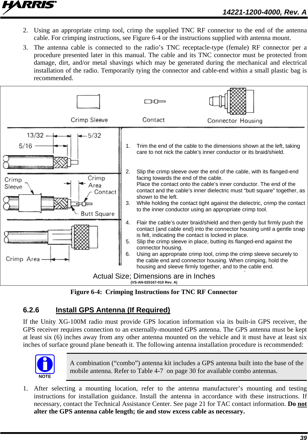
UserManual.wiki
>
Harris RF Communications Division
>
XG-100M00 User Manual
>
manual 2
Contents
1.
Manual 1
2.
Manual 2
3.
Manual 3
4.
manual 1
5.
manual 2
6.
manual 3
7.
User Manual 1
8.
User Manual 2
manual 2
Navigation menu
Upload a User Manual
Namespaces
Wiki Guide
HTML
PDF
Info
Views
User Manual
Discussion / Help
Navigation


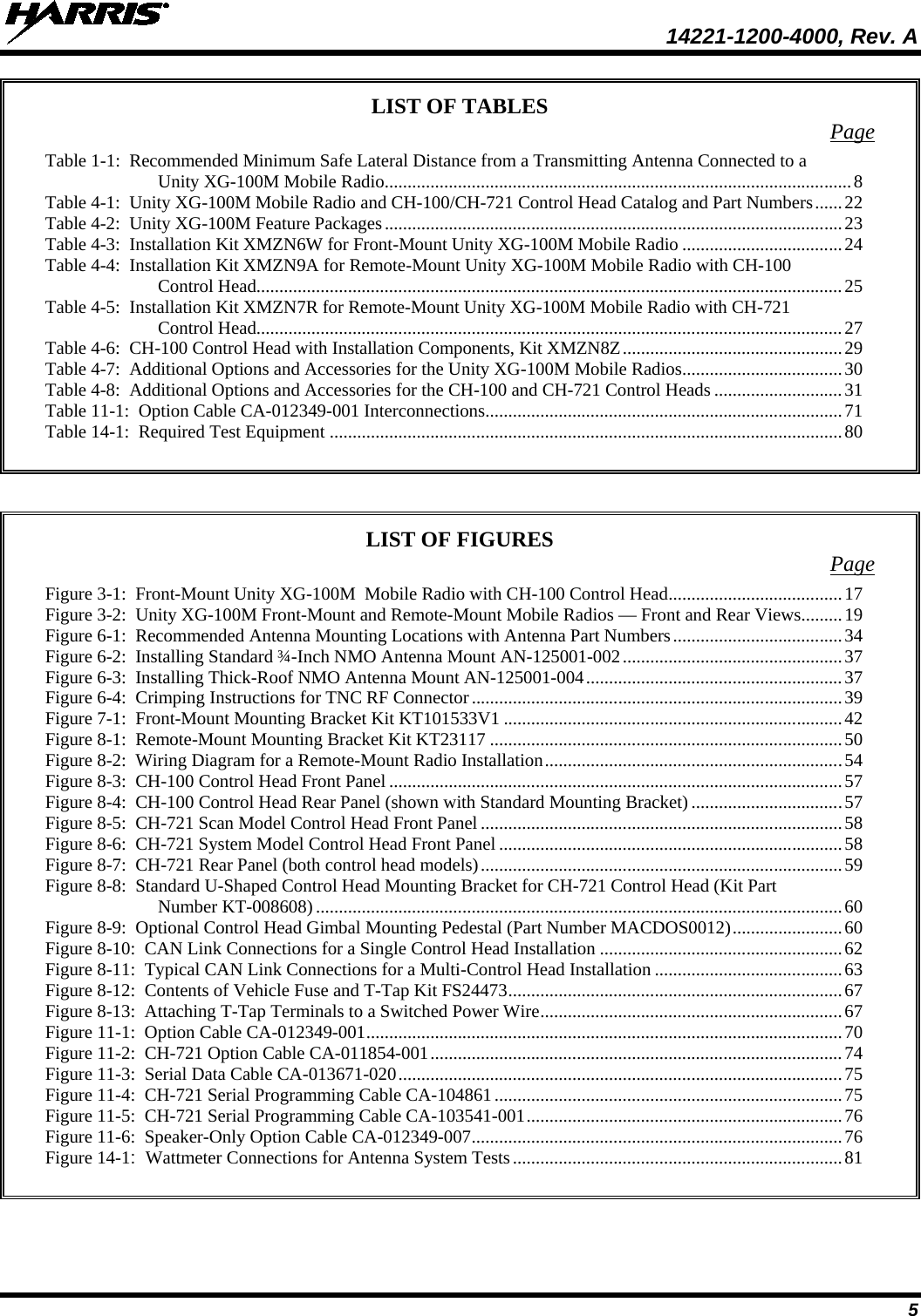
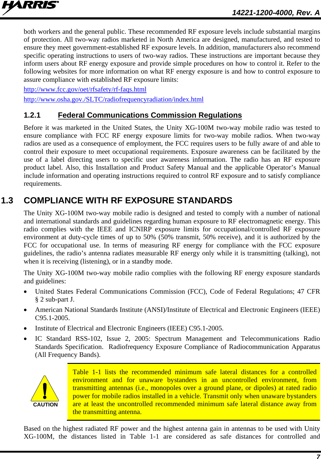
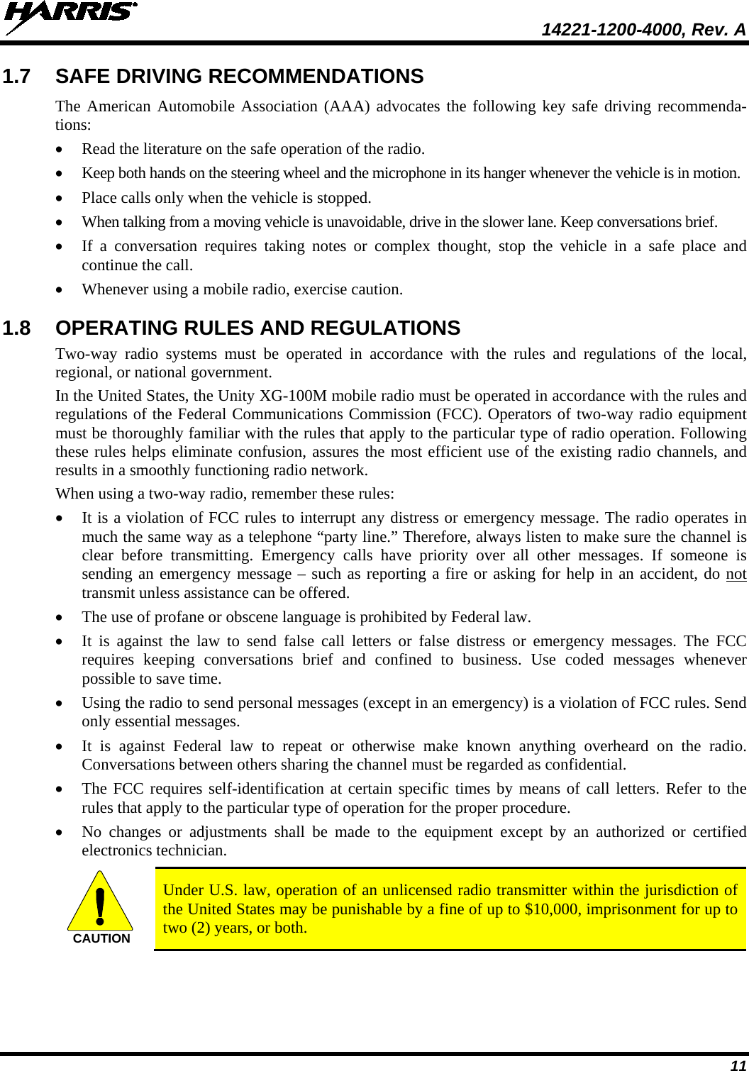
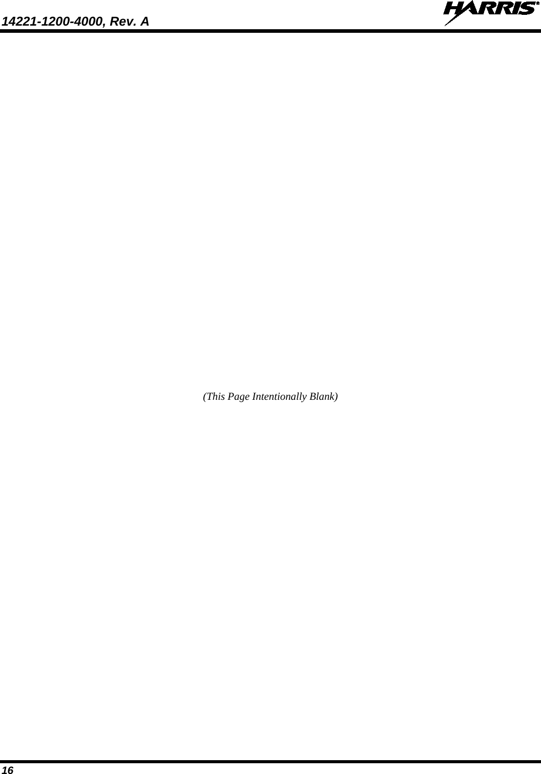
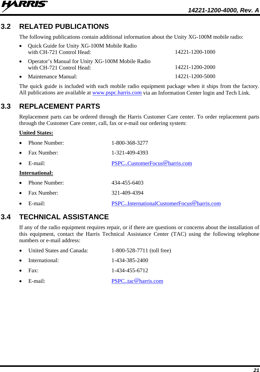
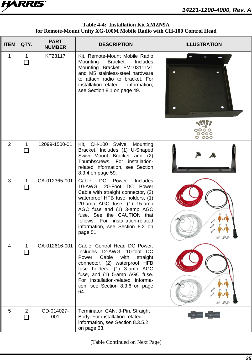
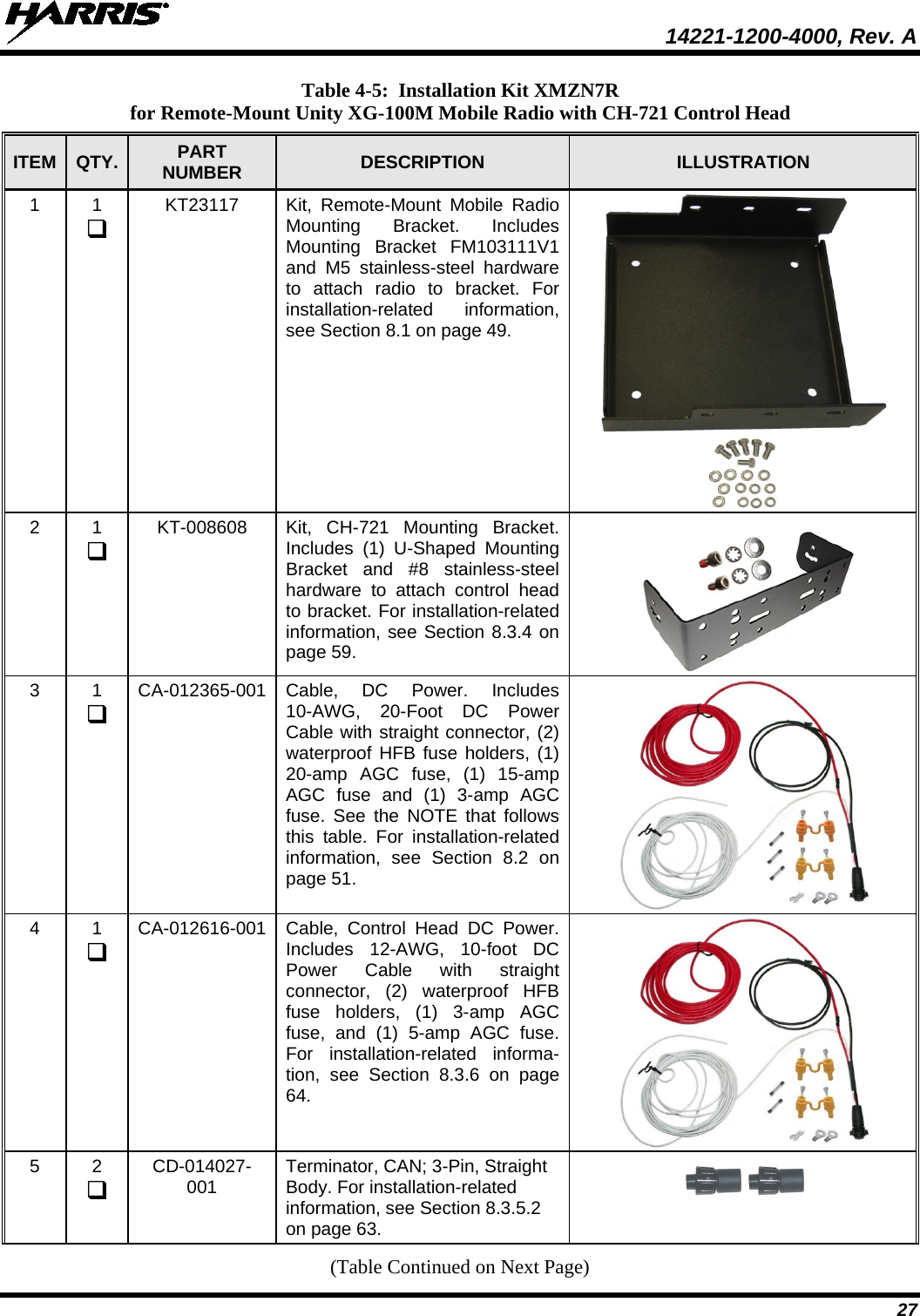
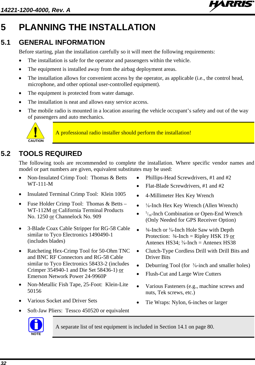
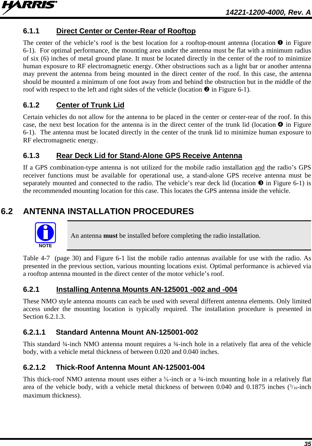
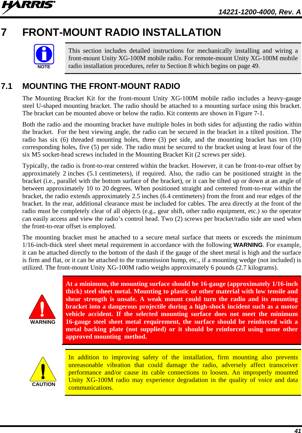
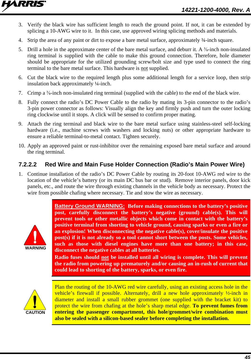
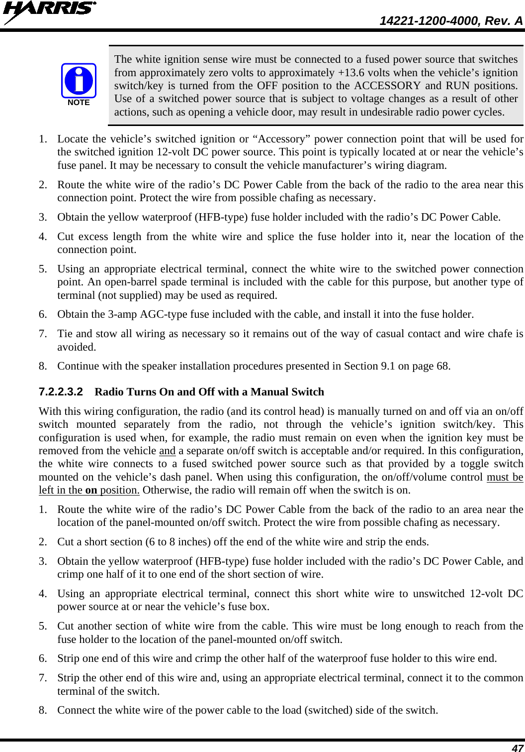
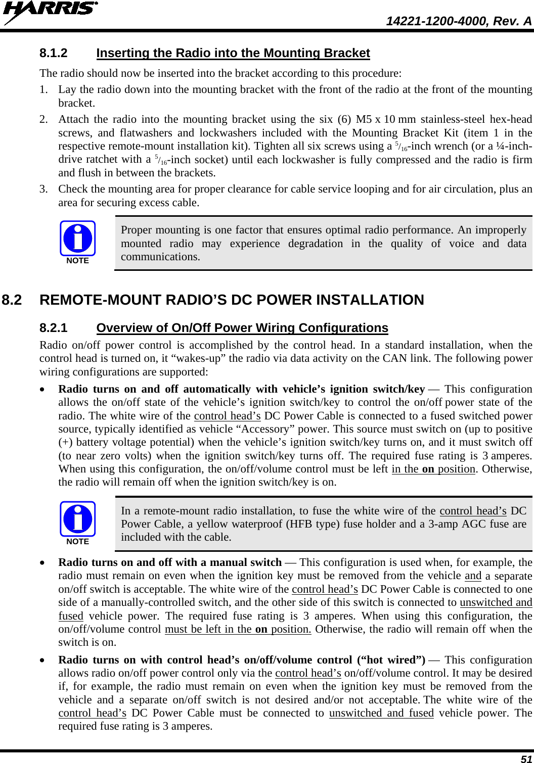
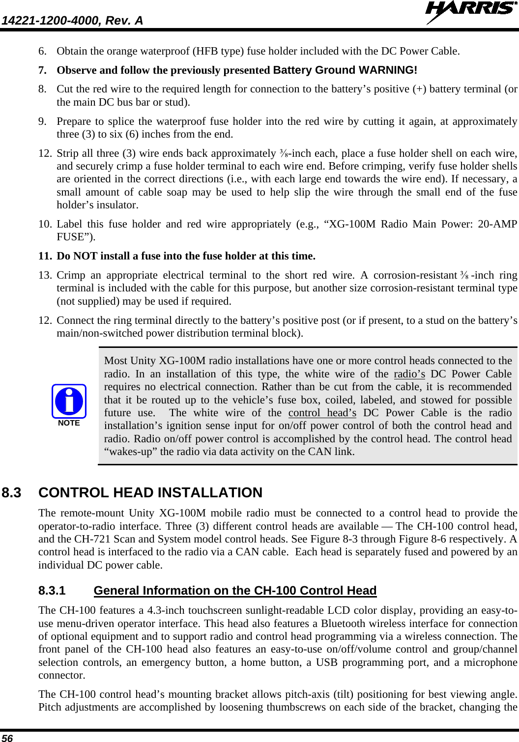
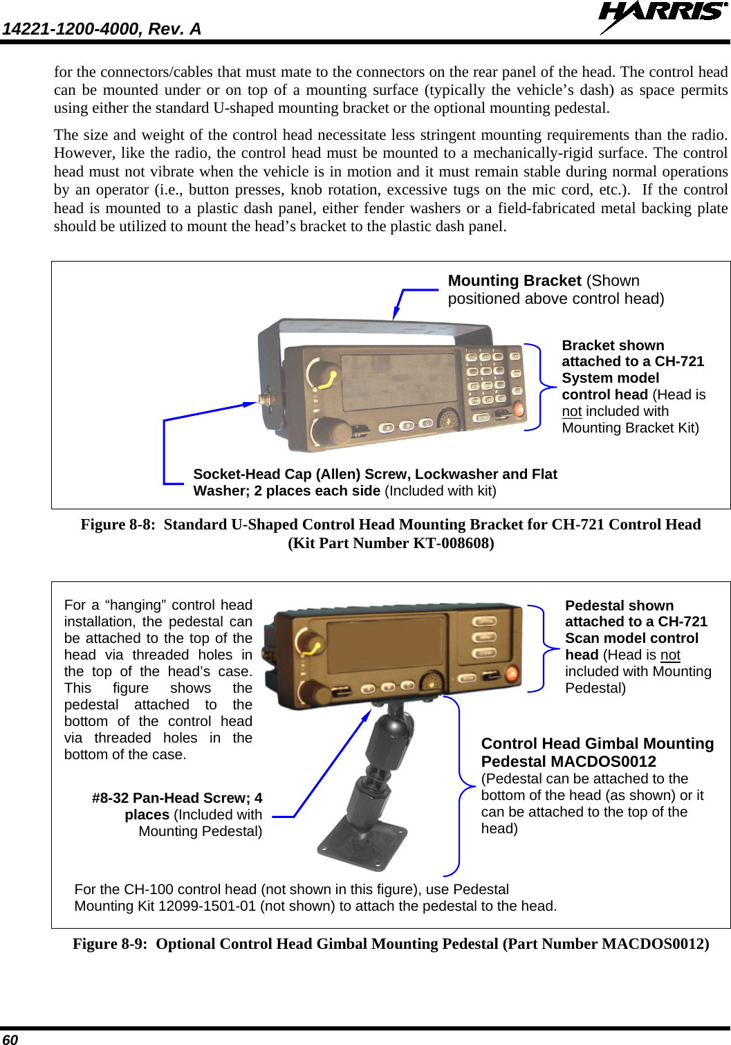
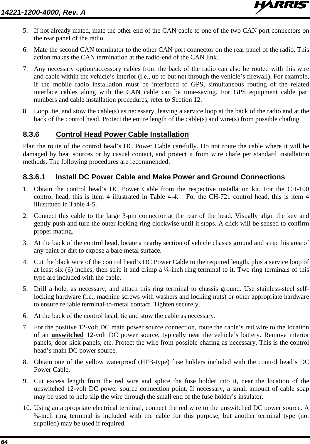
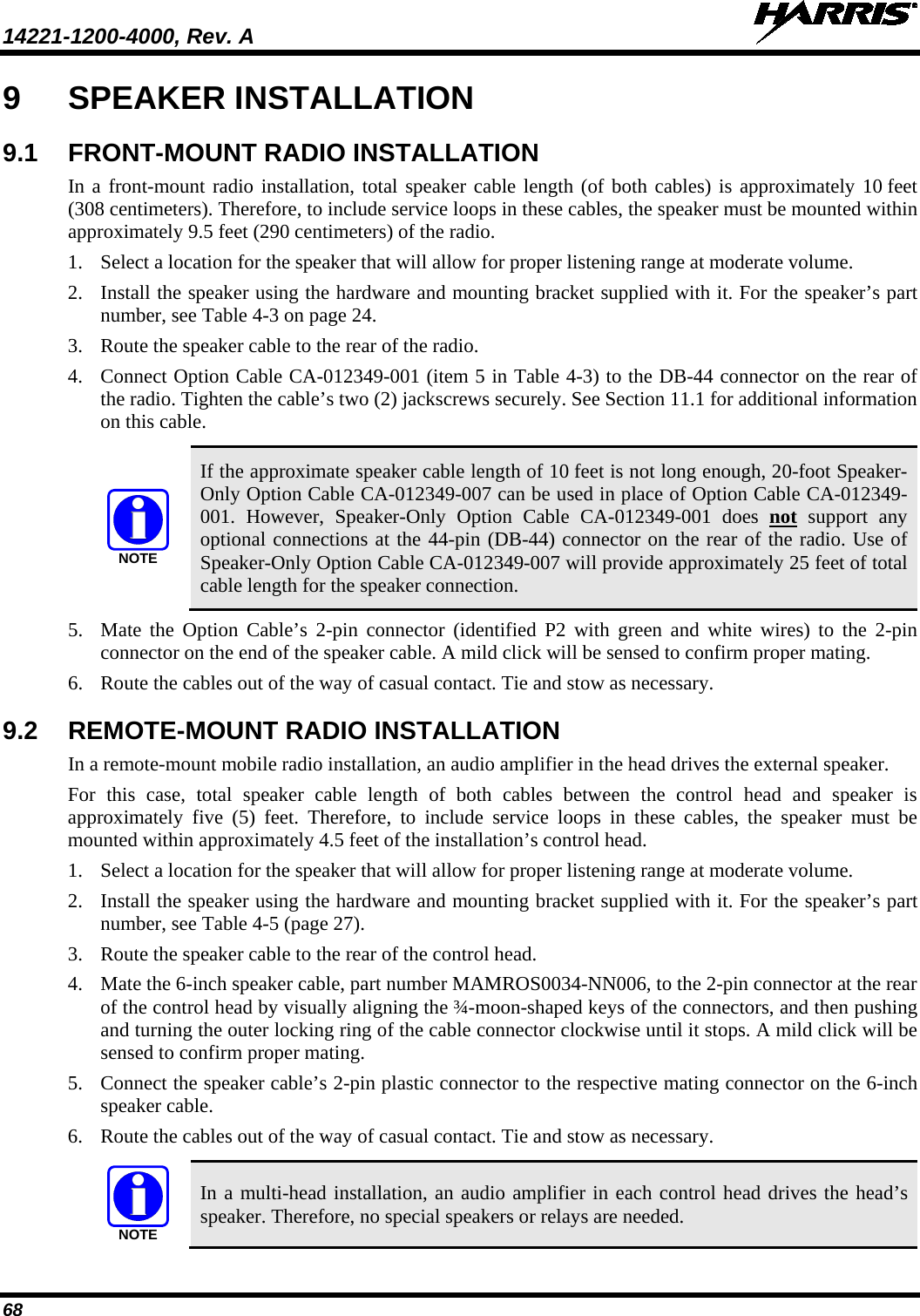
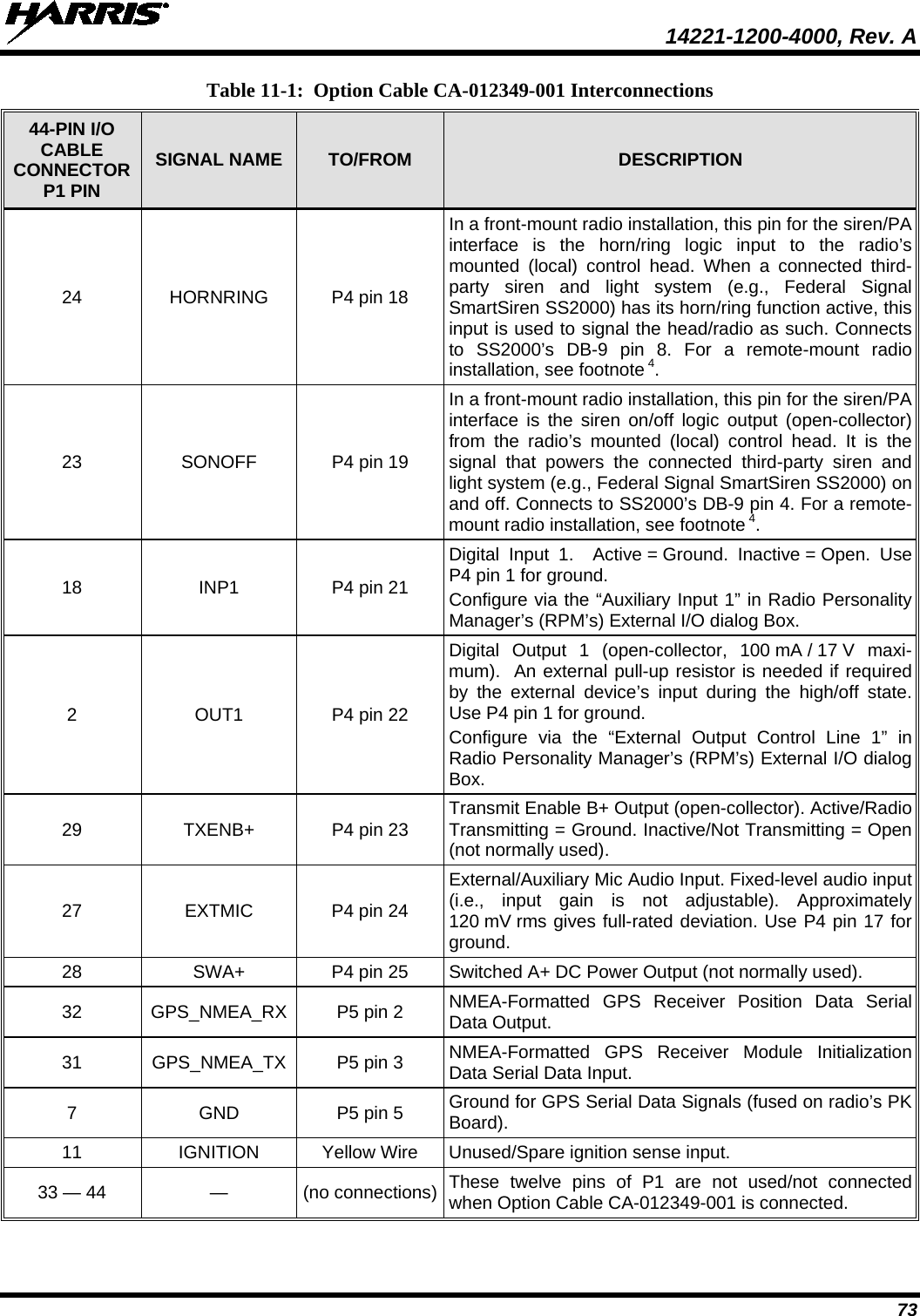
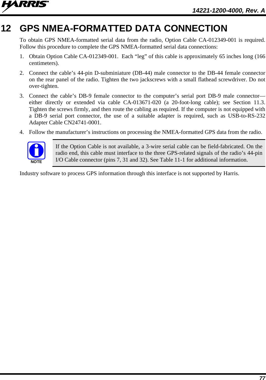
![14221-1200-4000, Rev. A 54 Figure 8-2: Wiring Diagram for a Remote-Mount Radio Installation CH-721 SCAN MODELCONTROL HEADCU23218-0002(MAMW-NCP9E)CH-721 SYSTEM MODELCONTROL HEADCU23218-0004(MAMW-NCP9F)DTMFMICROPHONEMC-103334-040 ORMC-103334-041(INCLUDED WITHMAMW-NMC9C)STANDARD MICROPHONEMC-101616-040 ORMC-101616-041(INCLUDED WITHMAMW-NMC7Z)ORNOISE-CANCELINGMICROPHONEMC-103334-050 ORMC-103334-051(INCLUDED WITHMAMW-NMC9D)CH-721 MOUNTING BRACKET KITKT-008608[SUPPLIED WITH INSTALLATION KIT]• IF IGNITION SENSE ON/OFF FUNCTIONALITY IS REQUIRED, CONNECT WHITE WIRE OF CONTROL HEAD’S DC POWER CABLE TO A SWITCHED 13 VDC POWER SOURCE USING THE SUPPLIED FUSE AND FUSE HOLDER.• IF IGNITION SENSE ON/OFF FUNCTIONALITY IS NOT REQUIRED, CONNECT WHITE WIRE OF CONTROL HEAD’S DC POWER CABLE TO AN UNSWITCHED 13 VDC POWER SOURCE USING THE SUPPLIED FUSE AND FUSE HOLDER.REAR VIEW OF CH-721CONTROL HEADNEG POS3-AMP FUSE & FUSE HOLDER (HFB TYPE) REDRED RED5-AMPFUSE& FUSE HOLDER (HFB TYPE)3-AMP FUSE & FUSE HOLDER(HFB TYPE)20-AMPFUSE & FUSE HOLDER(HFB TYPE)REDWHITEREDRINGTERMINALSVEHICLEDC POWER DISTRI-BUTION BLOCK(E.G., “POWER ACCESS POINT”)VEHICLE BATTERY+-NOTE: BATTERY GROUND (-) CONNECTION NOT INDICATED.CAN TERMINATORCD-014027-001[SUPPLIED WITH INSTALLATION KIT]REDWHITEBLACK(SHORT AS POSSIBLE)RING TERMINAL (CONNECT TO VEHICLE CHASSIS GROUND)CAN CABLE CA-009562-030 (30 FEET LONG) [SUPPLIED WITH INSTALLATION KIT]SPEAKER CABLEMAMROS0034-NN006[SUPPLIED WITHINSTALLATION KIT]EXTERNAL SPEAKERLS102824V10[SUPPLIED WITHINSTALLATION KIT] WHITE WIRE OF RADIO’S DC POWER CABLE (LABELED AND COILED NEAR VEHICLE’S FUSE BOX)DC POWER CABLE CA-012616-001(SUPPLIED WITH INSTALLATION KIT)VEHICLE FUSE BOX, ETC.WHITEREAR VIEW OF CH-100CONTROL HEADCH-100REMOTE-MOUNTCONTROL HEAD12099-1200-01(XMCP9R)CH-100 MOUNTING BRACKET KIT12099-1500-01[SUPPLIED WITH INSTALLATION KIT]](https://usermanual.wiki/Harris-RF-Communications-Division/XG-100M00.manual-2/User-Guide-1566531-Page-54.png)
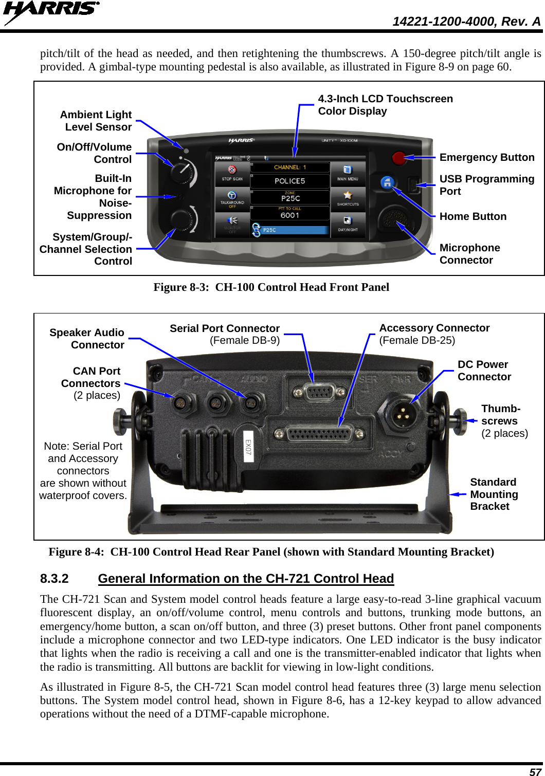
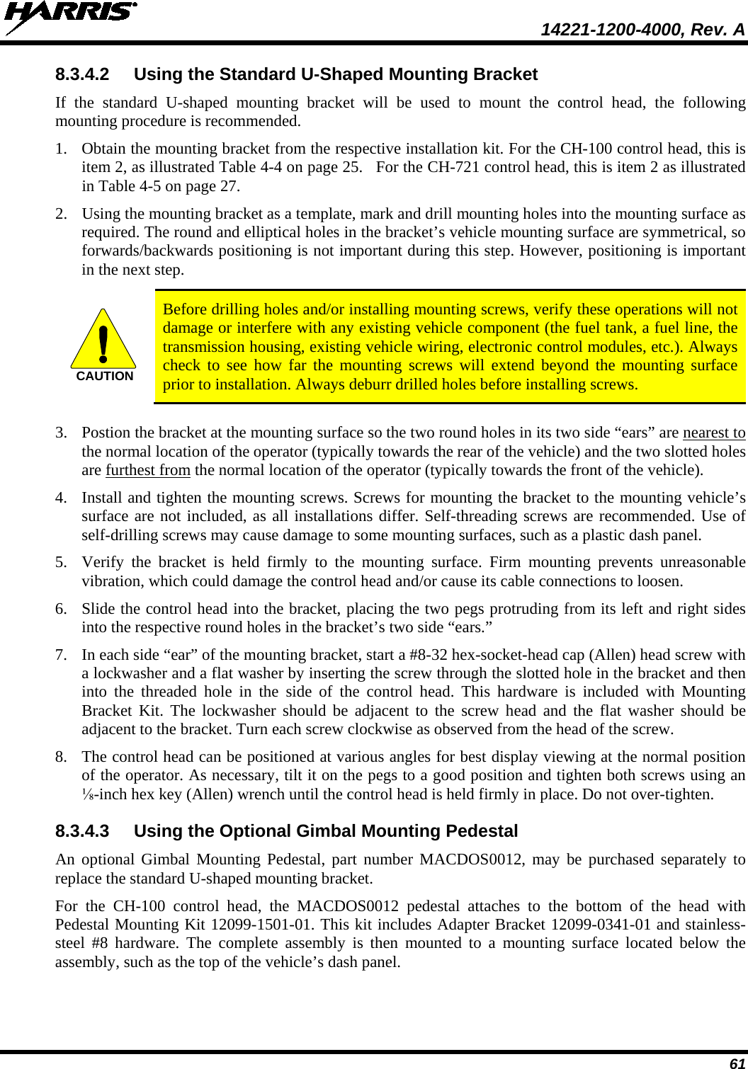
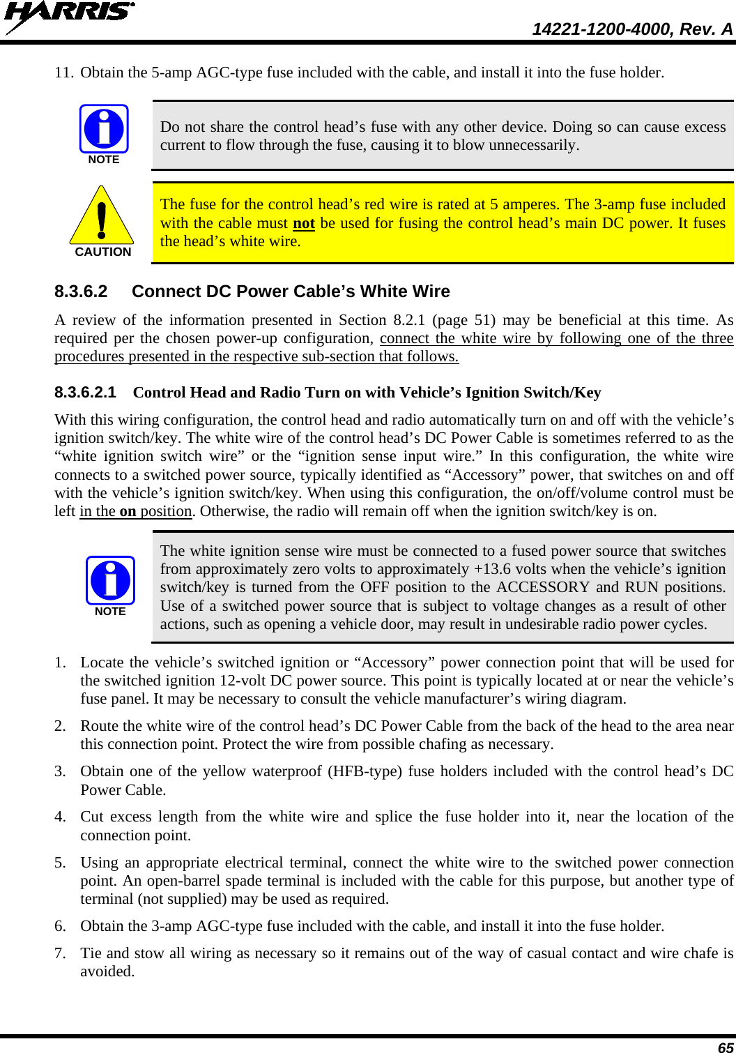
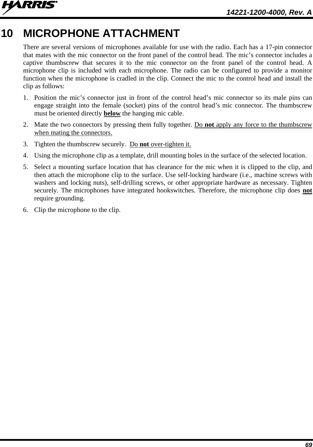
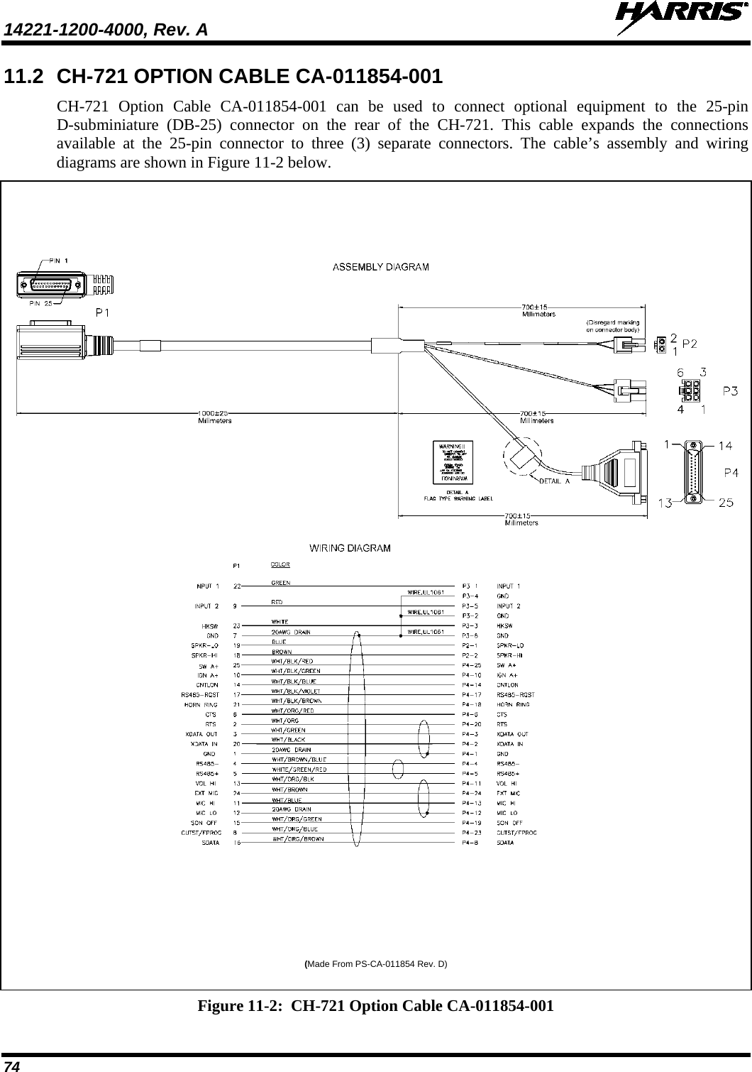
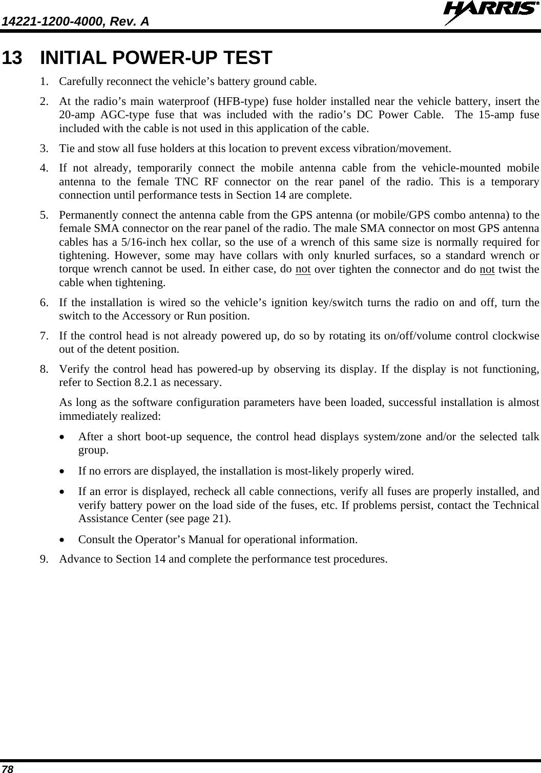
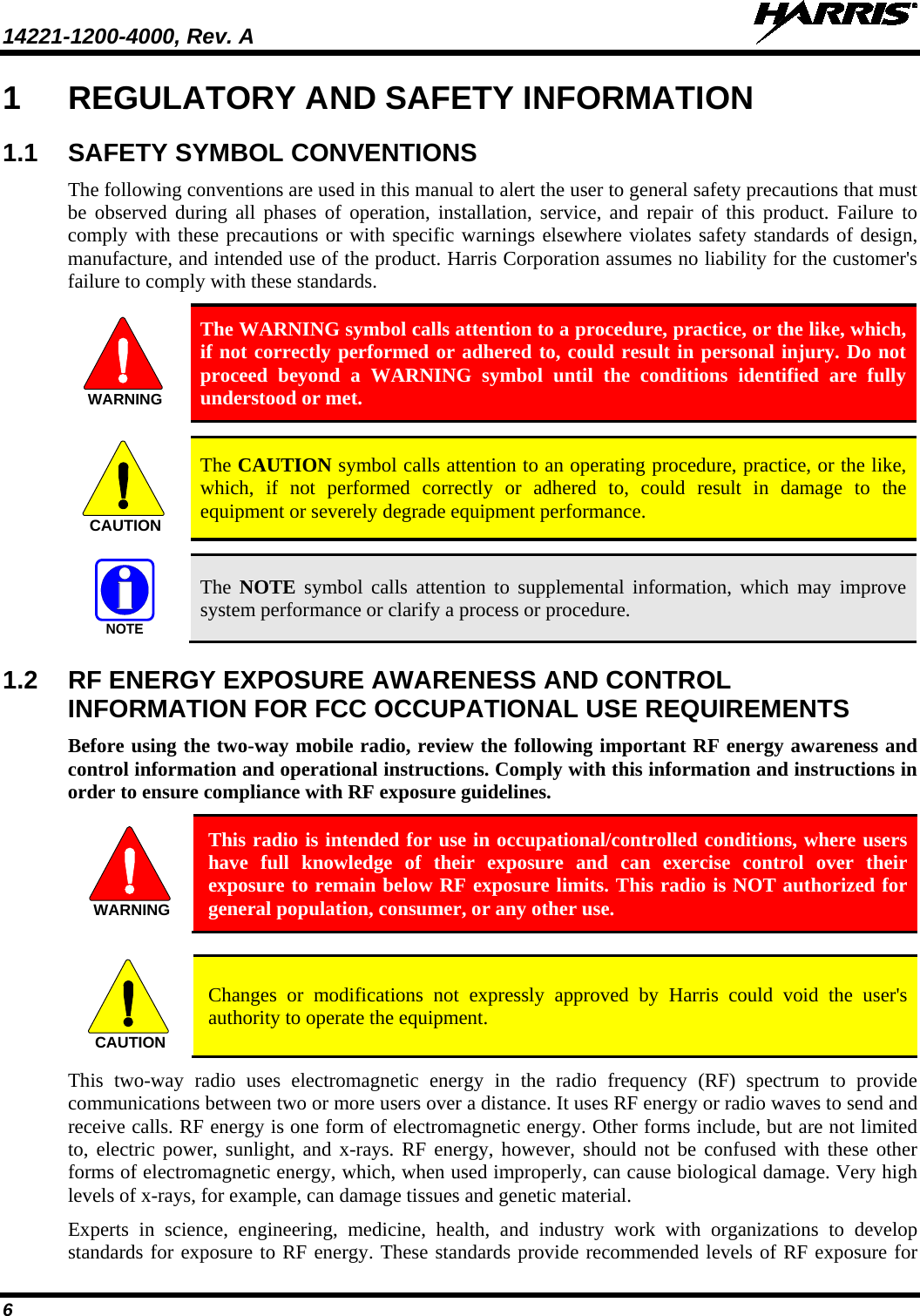
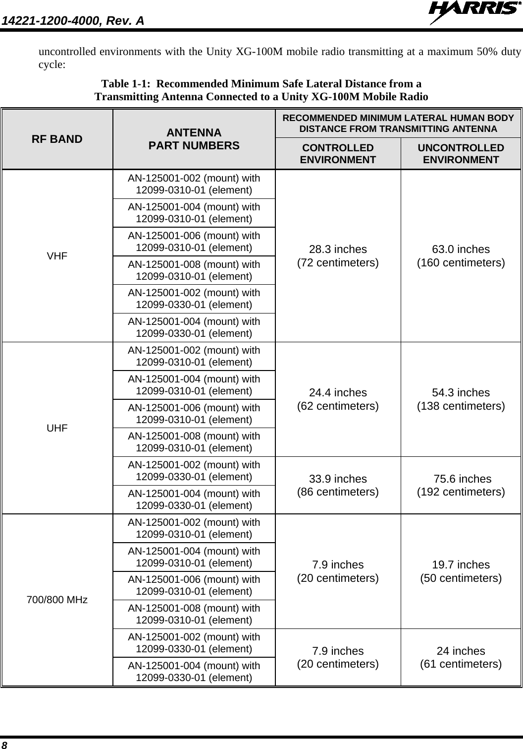
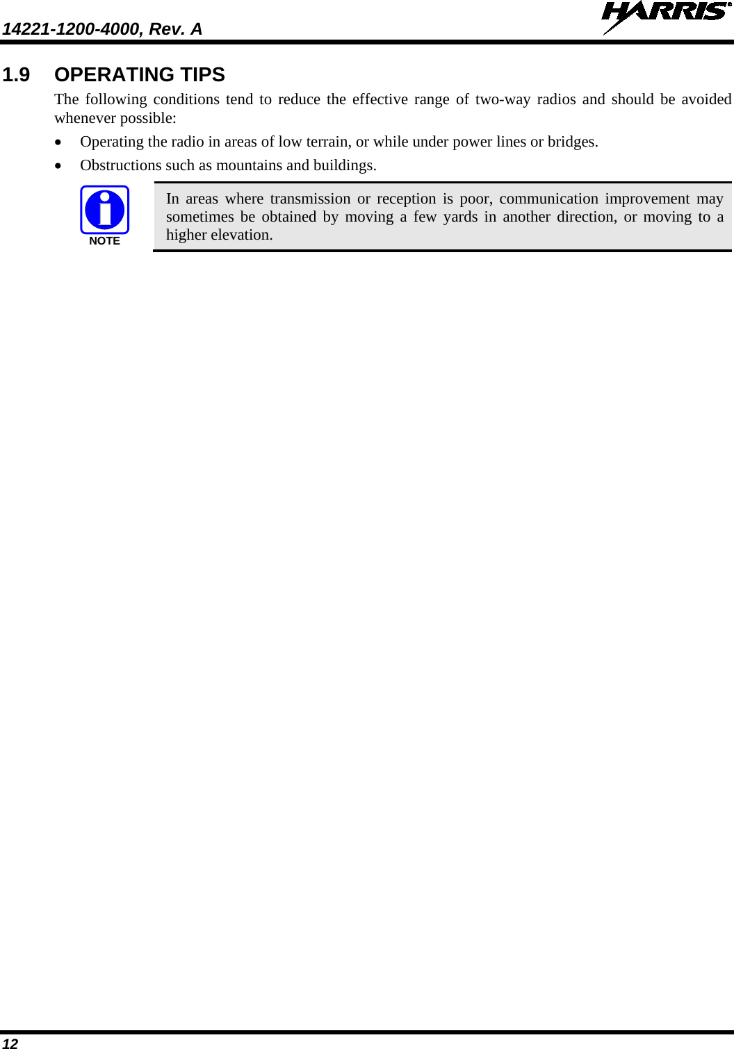
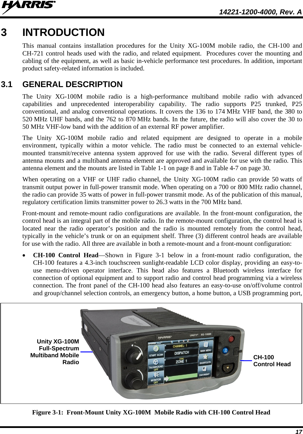
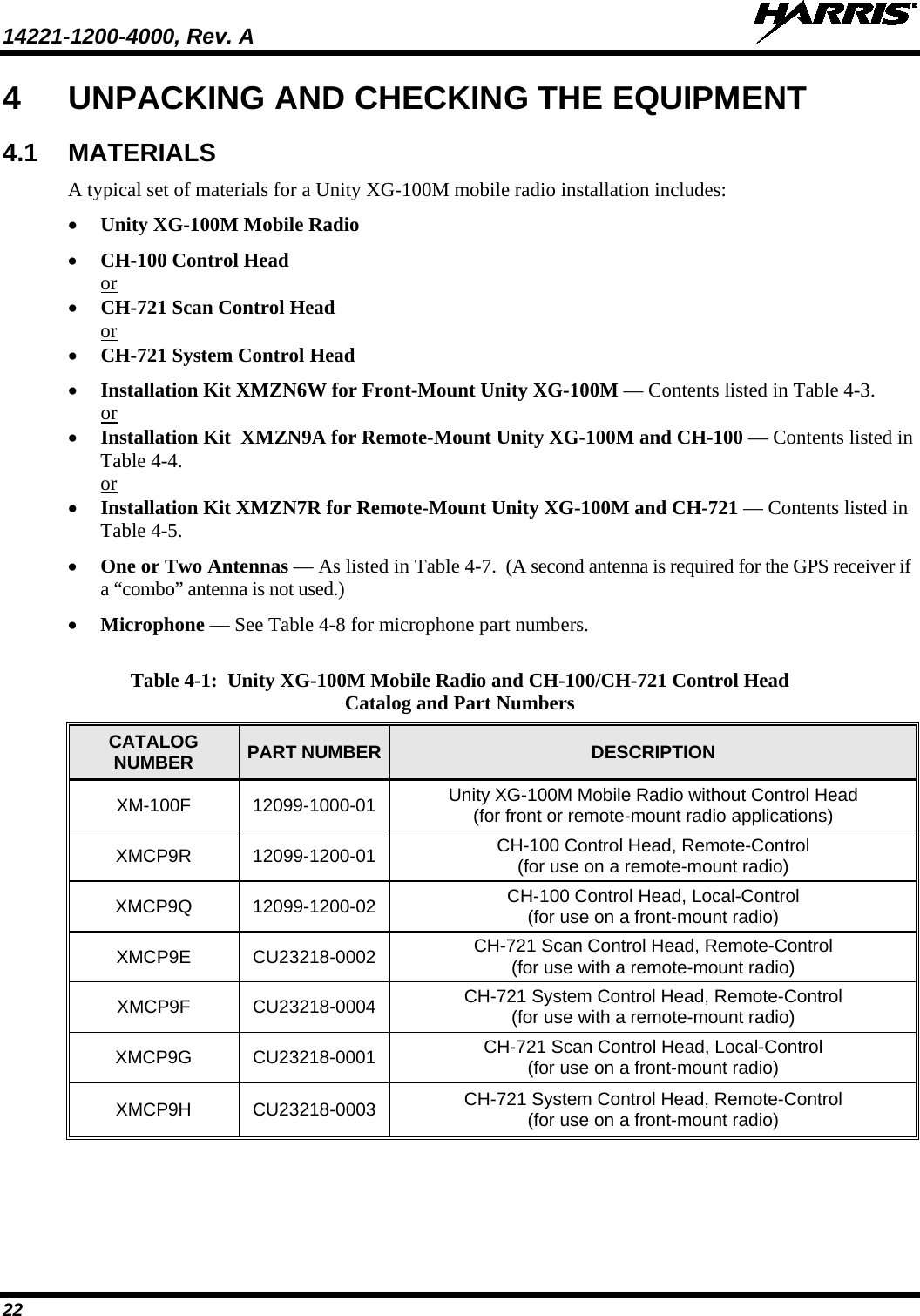
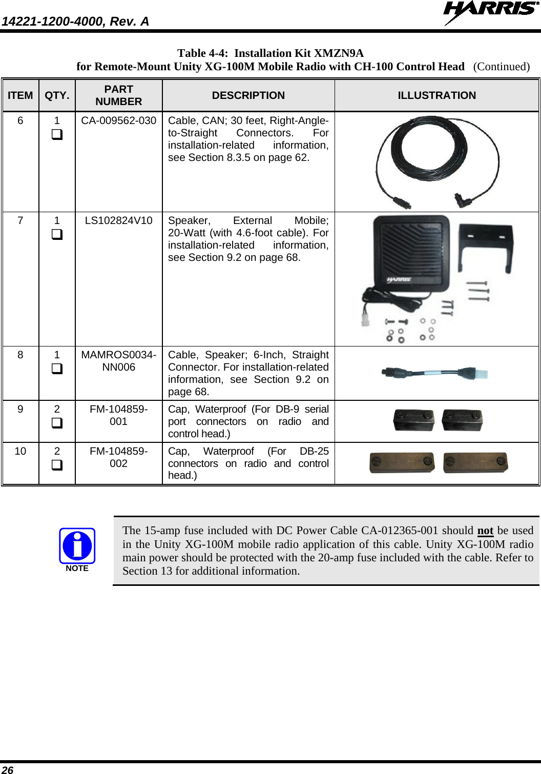
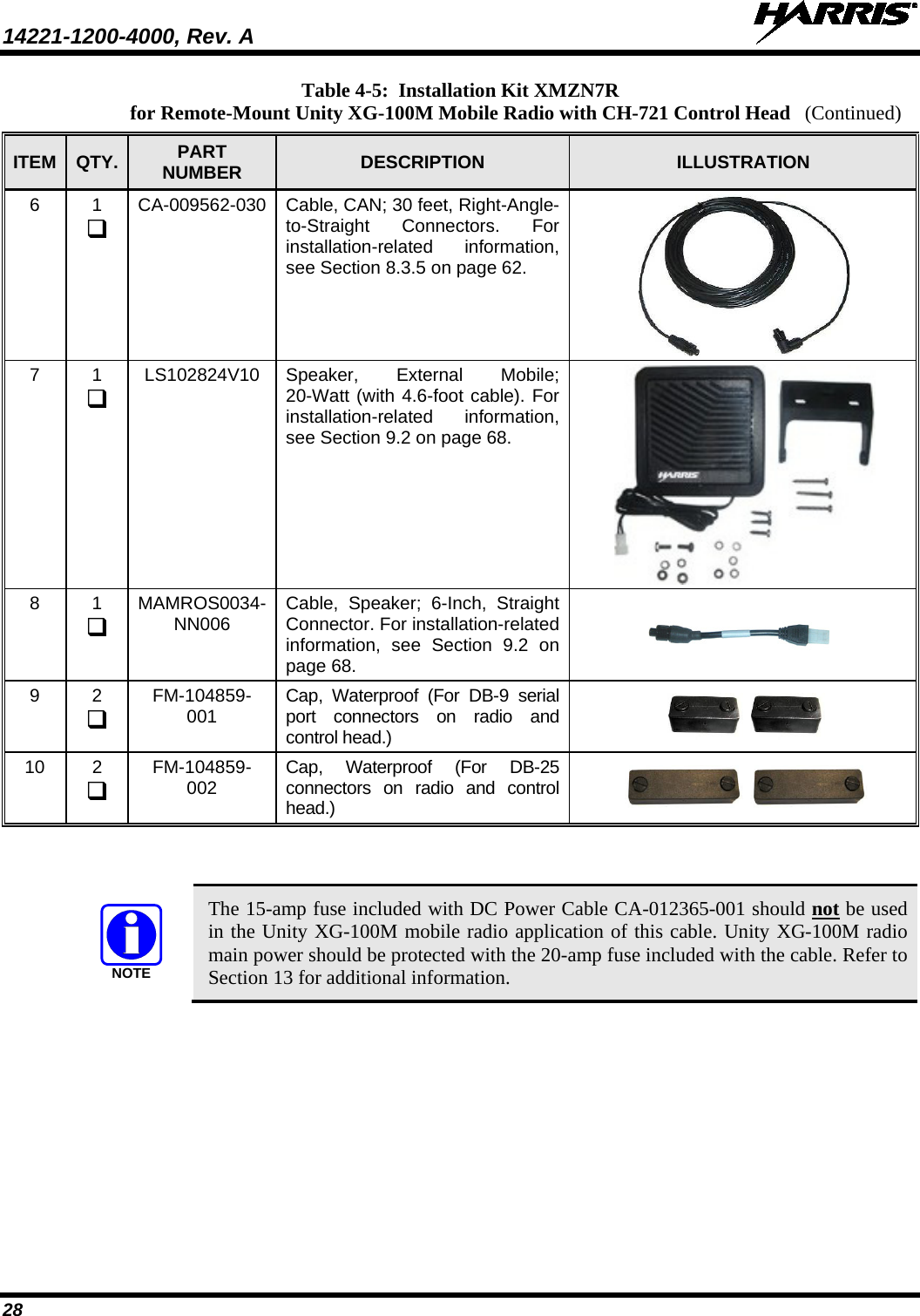
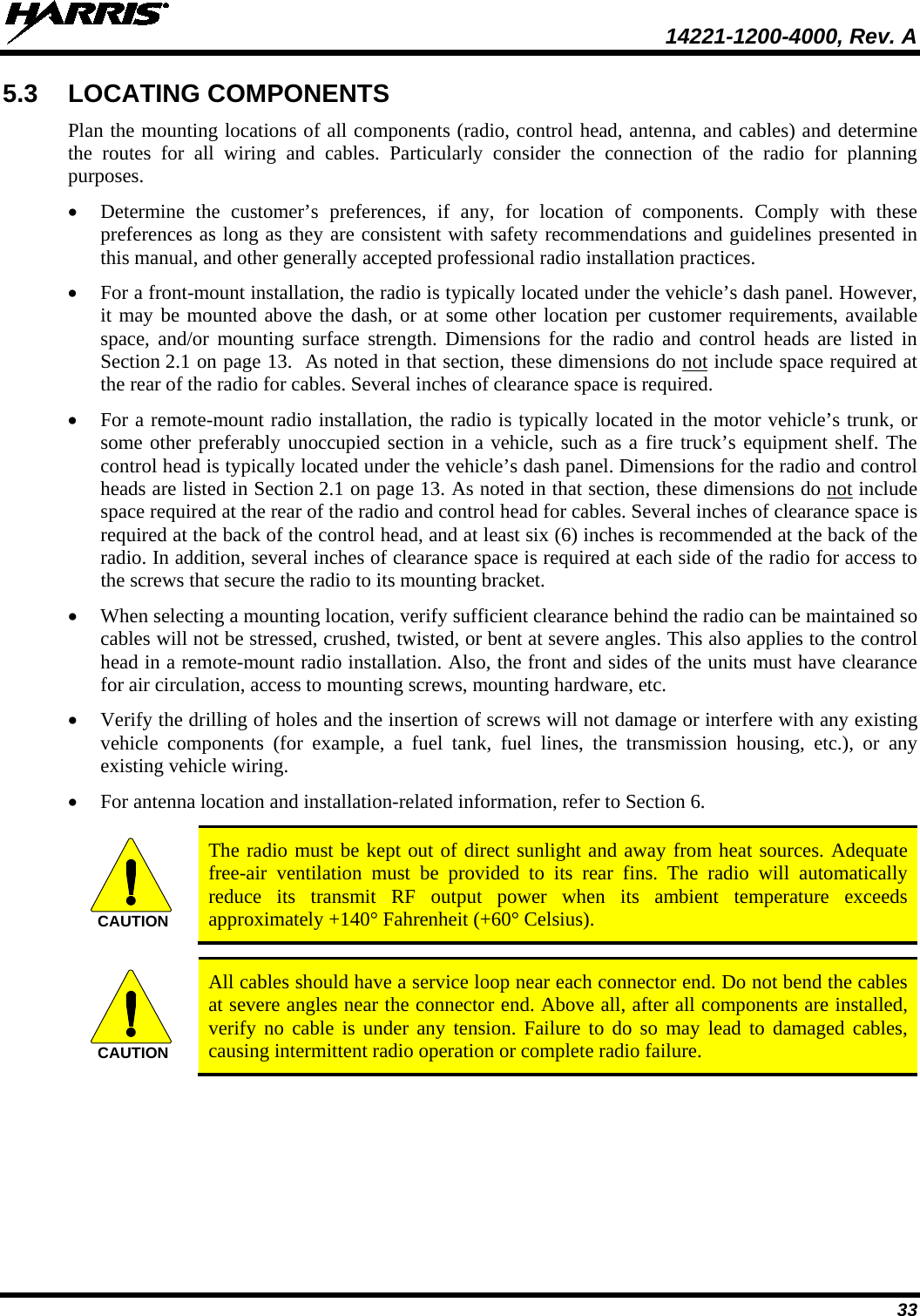
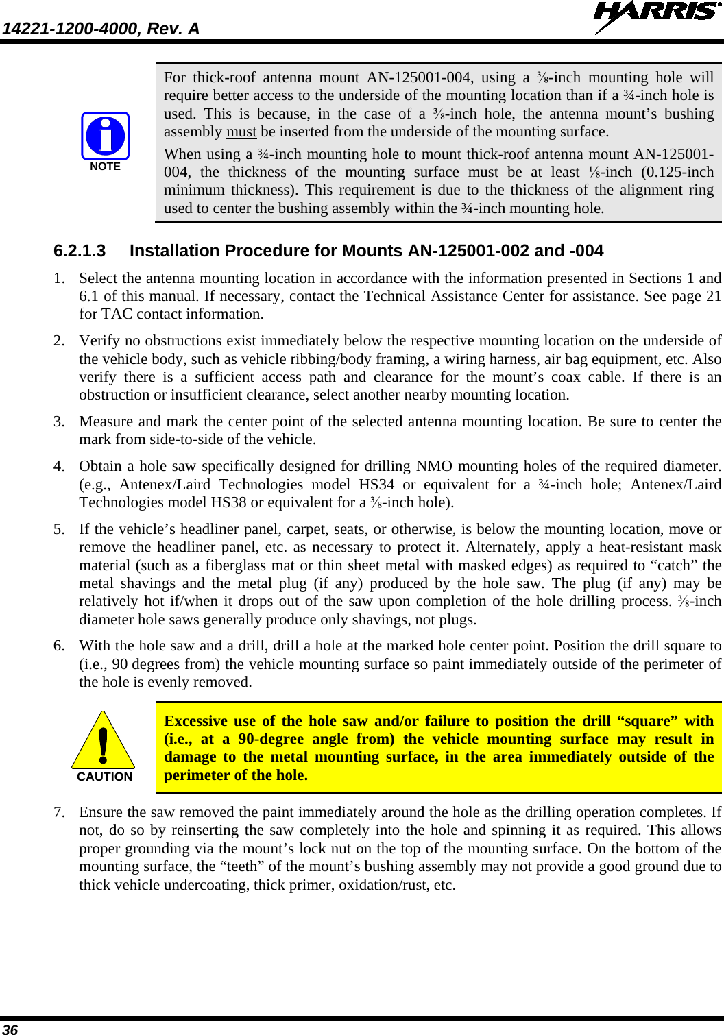
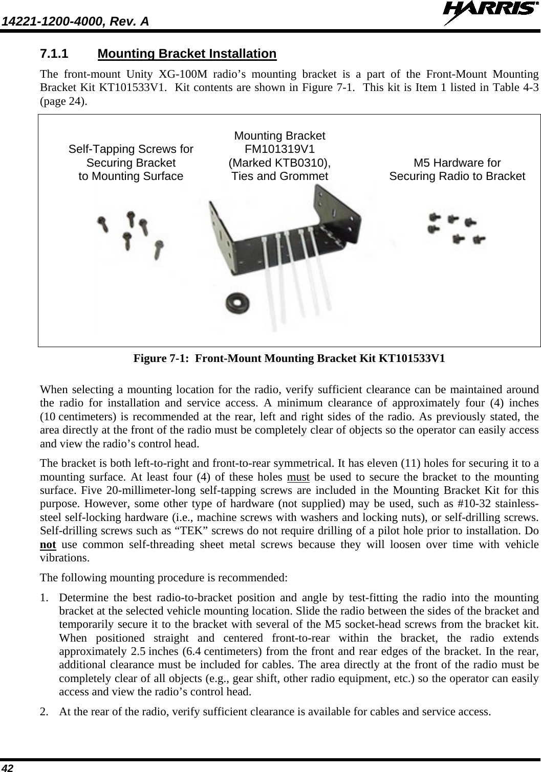
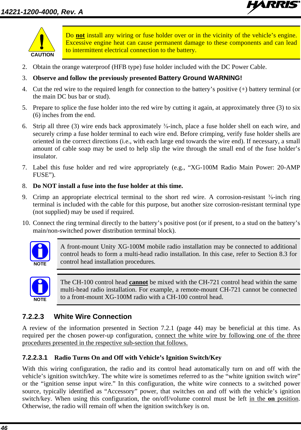
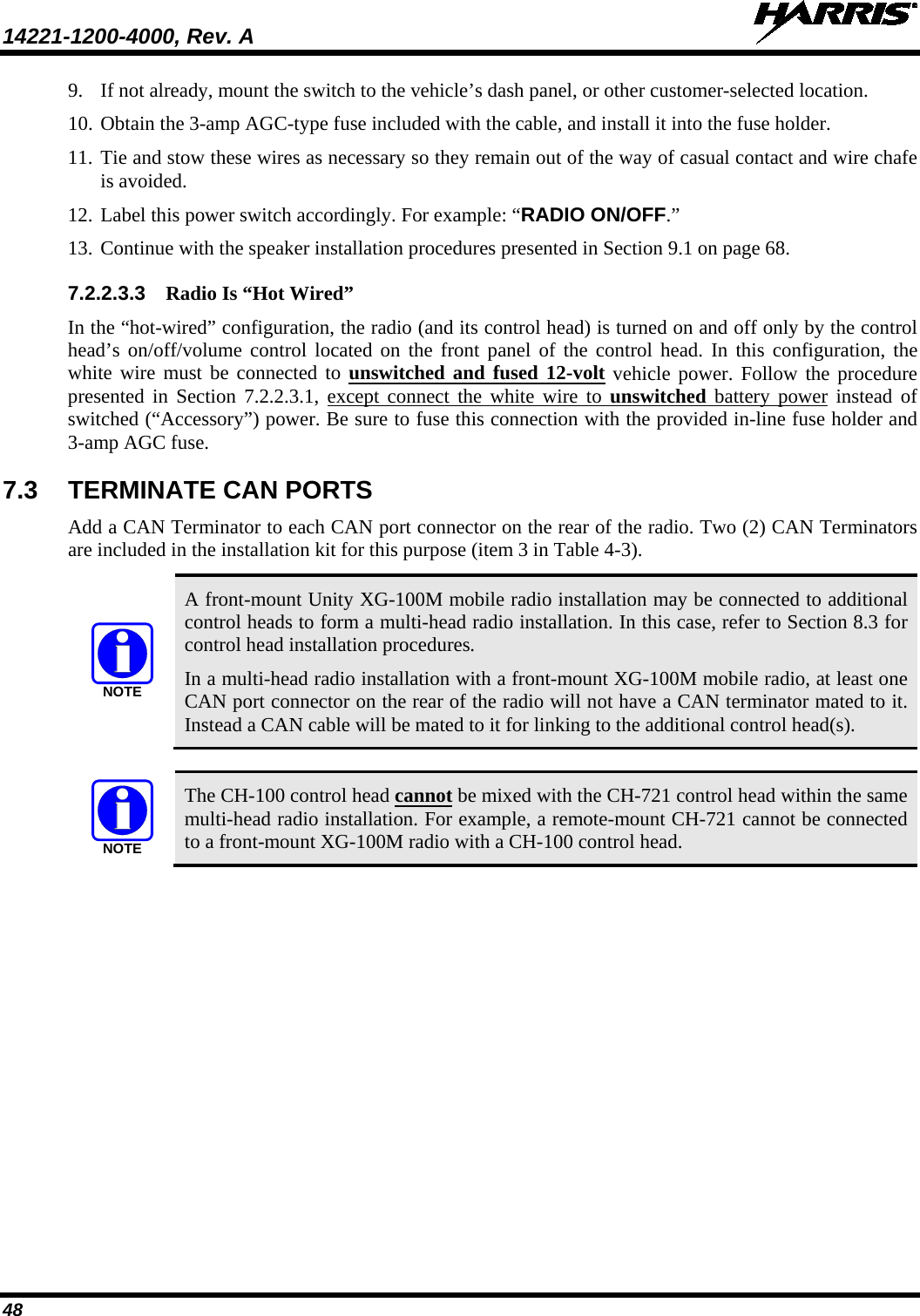
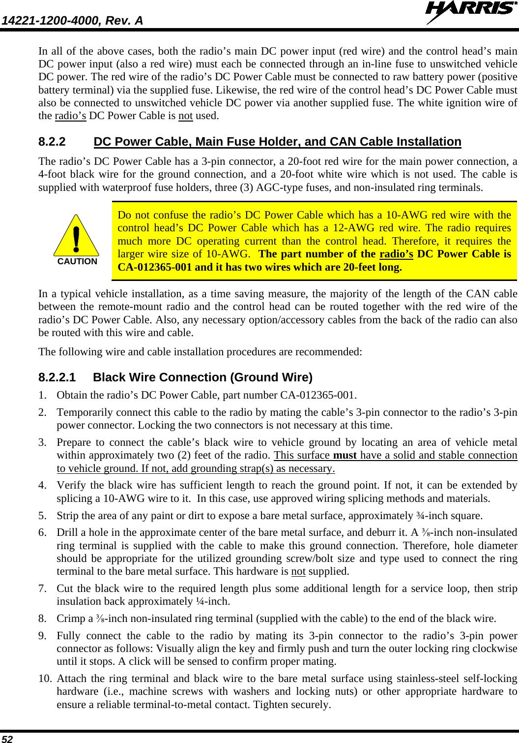
![14221-1200-4000, Rev. A 55 Figure 8-2: Wiring Diagram for a Remote-Mount Radio Installation (Cont.) DC POWER CABLECA-012365-001(SUPPLIED WITH INSTALLATION KIT)RING TERMINAL (CONNECT TO VEHICLE CHASSIS GROUND)BLACKREDWHITEUNITY XG-100M MOBILE RADIO12099-1000-01(XM 100F)REAR VIEWMULTI-BAND MOBILEANTENNAELEMENT(OPTIONAL;SEE TEXT FOR PART NUMBER)MALE TNC RF CONNECTOR(SUPPLIED WITH ANTENNA MOUNTING BASE)CAN TERMINATORCD-014027-001[SUPPLIED WITH INSTALLATION KIT]GPS ANTENNA(OPTIONAL; SEE TEXT FOR SPECIFIC PART NUMBERS)REMOTE-MOUNT RADIO MOUNTING BRACKET KITKT23117 (NOT SHOWN)[SUPPLIED WITH INSTALLATION KIT]ANTENNAMOUNTING BASE (OPTIONAL;SEE TEXT FOR SPECIFIC PART NUMBERS)15-FOOT (MINIMUM) COAX CABLE IS A PART OF MOUNTING BASE](https://usermanual.wiki/Harris-RF-Communications-Division/XG-100M00.manual-2/User-Guide-1566531-Page-55.png)