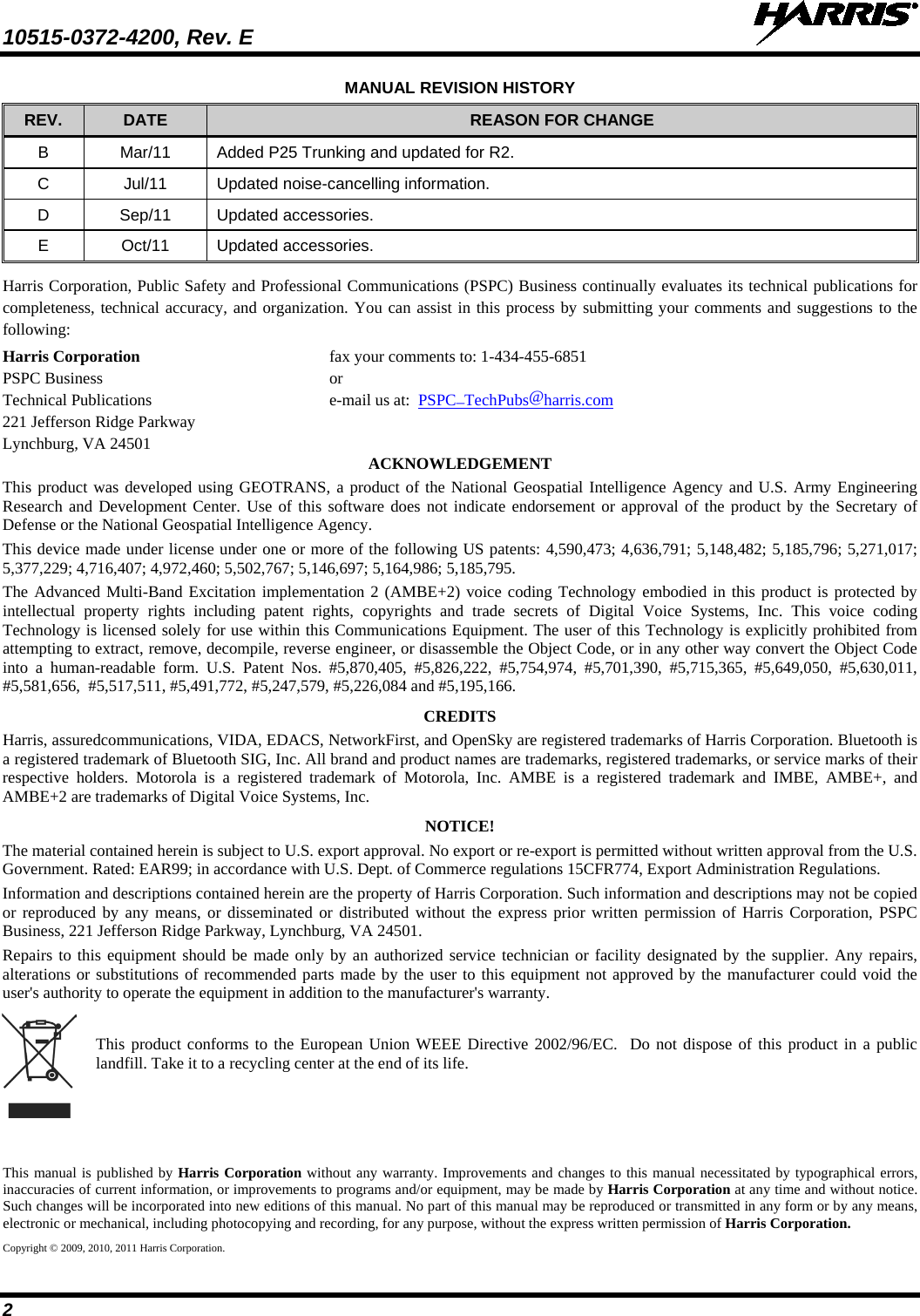
Harris RF Communications Division XG-100P00 Unity Multiband Portable User Manual
Harris Corporation RF Communications Division Unity Multiband Portable
UserManual.wiki
>
Harris RF Communications Division
>
XG-100P00 User Manual
>
User Manual
Contents
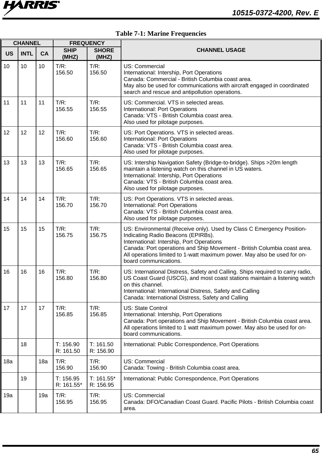
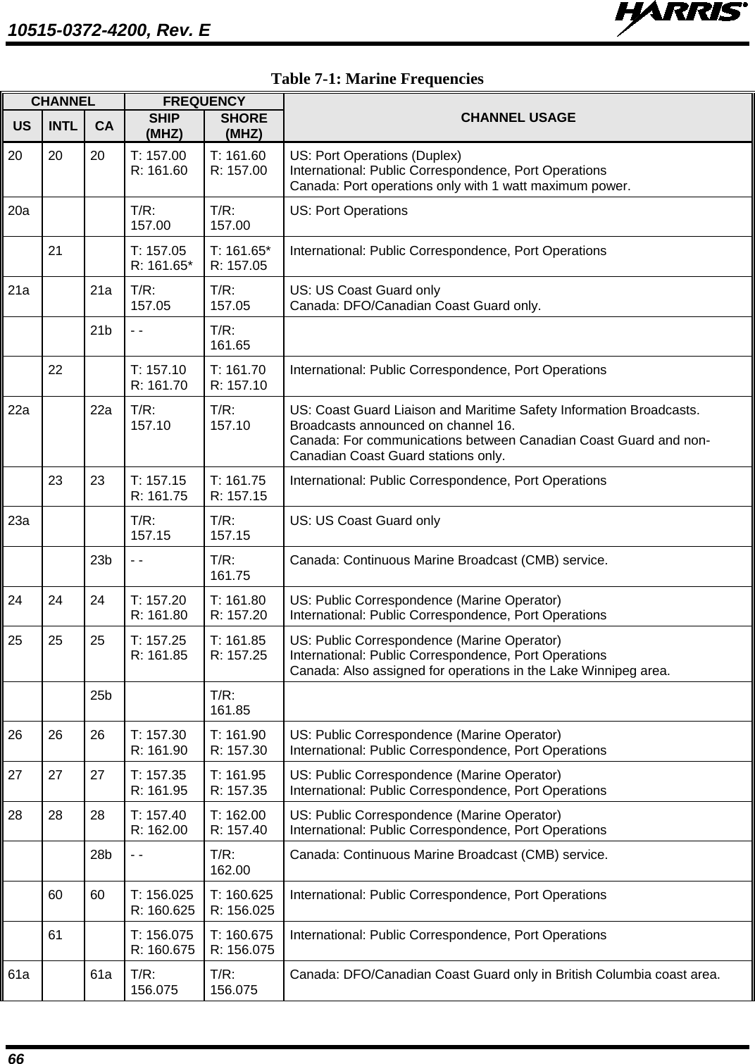
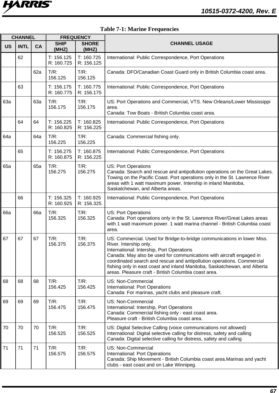
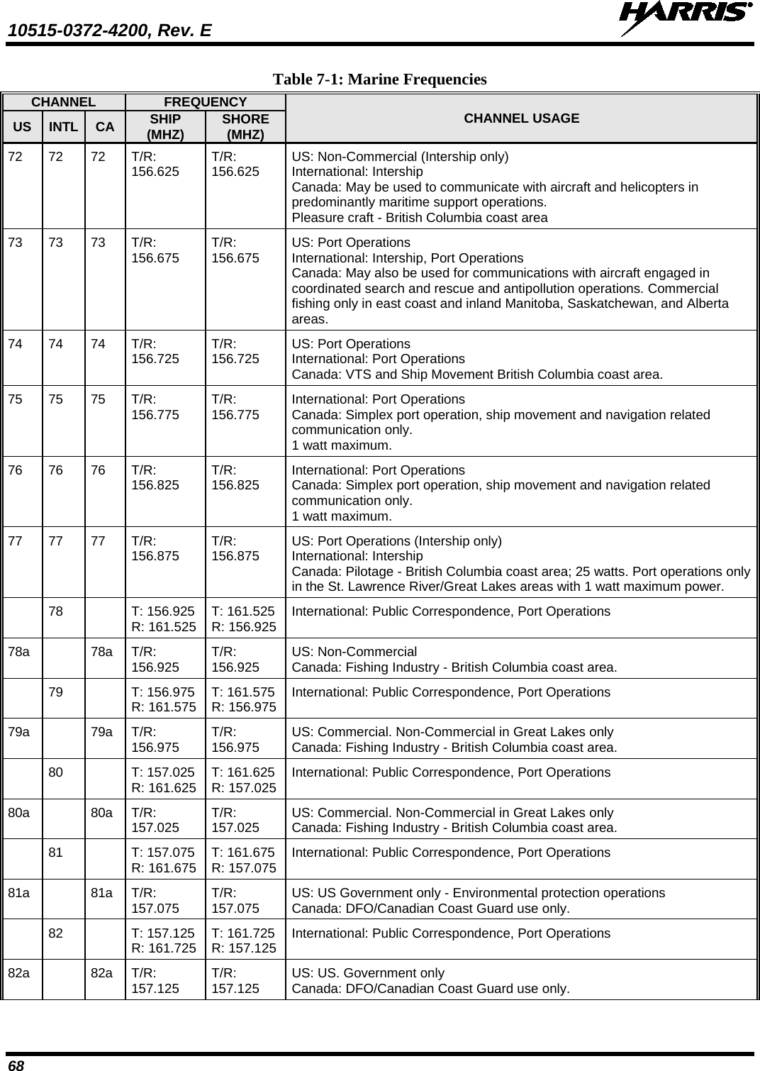
1.
Manual 1
2.
manual safety
3.
User Manual
User Manual
Navigation menu
Upload a User Manual
Namespaces
Wiki Guide
HTML
PDF
Info
Views
User Manual
Discussion / Help
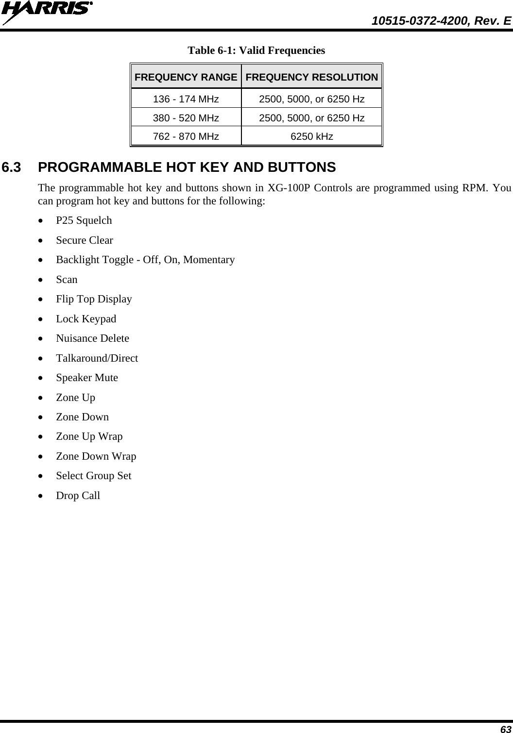
Navigation
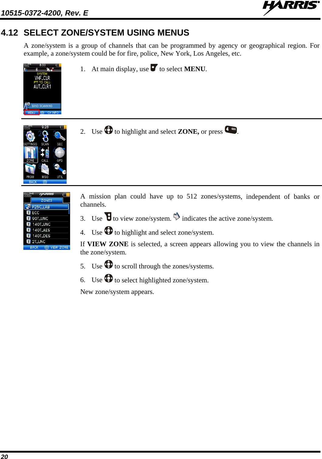
![10515-0372-4200, Rev. E 8 2. INTRODUCTION 2.1 DESCRIPTION Your XG-100P provides full-spectrum multiband coverage: • 136 to 174 MHz, VHF, 1 watt, 2 watts, 3 watts, 6 watts output • 380 to 520 MHz, UHF-Low, UHF-High, 1 watt, 2 watts, 3 watts, 5 watts output • 762 to 870 MHz, 700/800 bands, 0.5 watt, 1 watt, 2 watts, 3 watts output The XG-100P has the following capabilities: • Project 25 (P25) Conventional • P25 Trunking • Analog FM • Advanced Encryption Standard, 256-bit (AES-256) • Digital Encryption Standard Output Feedback (DES-OFB) Encryption • Digital Encryption Standard Cipher Feedback (DES-CFB) Encryption • Global Positioning System (GPS) • Bluetooth® • Over The Air Rekey (OTAR) • Preemptive Priority Scanning • Global Common Key References (CKR) • Smart Battery status and reporting • Feature Management (Using Radio Personality Manager [RPM] R6A or later) For optional accessories, refer to 7.2. Additional accessories may have been added since publication of this manual; contact Harris for more information. 2.2 STORAGE GUIDELINES Store your XG-100P and batteries in a clean, cool (not exceeding 86 °F [+30 °C]), dry, and ventilated storage area.](https://usermanual.wiki/Harris-RF-Communications-Division/XG-100P00.User-Manual/User-Guide-1599011-Page-8.png)
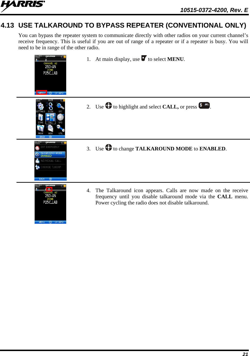
![10515-0372-4200, Rev. E 31 NOTE The XG-100 does not support KID 0000. Attempting to load a key with KID 0000 from the KVL will result in the failure UNKNOWN ERRICHECK TARGETALGORITHM! displayed on the KVL. KID 0000 is reserved for the Suppressed Key feature. 8. Enter a hexadecimal number as the Key value. DES-OFB keys are 16 digits while AES keys are 64 digits (32 bytes [256 bits]). Odd parity checks are made between every two digits for DES-OFB keys. Parity checks are not made for AES-256 keys. 9. KVL 3000 Plus will display SLOT FILLED, press ENTER. 10. A message is displayed when complete: KEY WAS CREATED SUCCESSFULLY. 11. Refer to Section 5.2 for loading a key into the radio. 5.1.3 Create Keygroup in the KVL 3000 Plus You can generate a group of Type-3 keys in the KVL 3000 Plus: 1. Turn on the KVL 3000 Plus. 2. Select Esc. 3. Select GROUPS. 4. Select NEW. 5. Enter a Group Name (up to seven characters). 6. Select CKRs from the programmed list until all desired CKRs are selected. 7. Select DONE. Refer to Section 5.2 for loading a keyset into the radio. 5.2 LOAD KEYS 5.2.1 Load UKEKs with UKEK Loader and RPM (for OTAR-Enabled Systems) UKEKs are loaded into Harris OTAR radios using the UKEK Loader application. UKEK Loader is a part of Key Manager. To load encryption keys: 1. Obtain the UKEK file and Storage Location Number (SLN) Binding Report information from the Crypto Officer (CO). NOTE Both AES and DES UKEKs can be contained within the same UKEK file. 2. If not already on, power-up the PC that has RPM and the UKEK Loader applications installed on it, and start Windows. 3. Connect the radio to the PC using programming cable 12082-0410-A1. NOTE The Unity drivers must be installed before UKEKs can be loaded into the radio. The Unity drivers may be found on the Key Loader CD (“unity setup.exe”) or on the Key Admin CD (“unity setup.exe”).](https://usermanual.wiki/Harris-RF-Communications-Division/XG-100P00.User-Manual/User-Guide-1599011-Page-31.png)
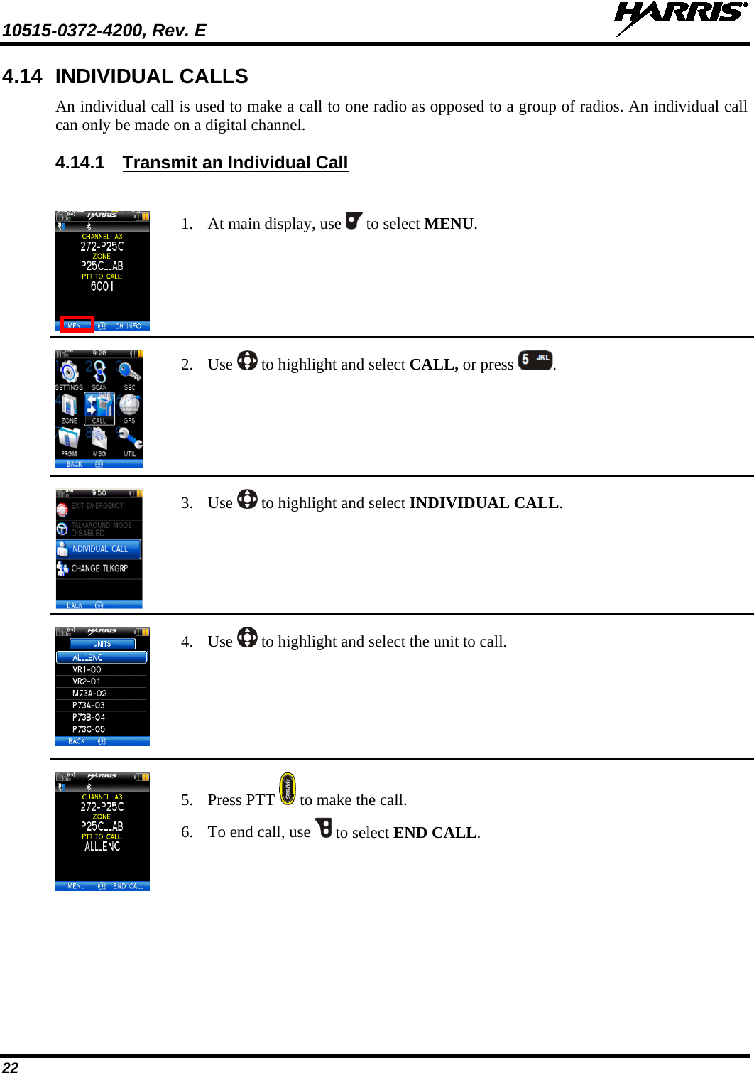
![10515-0372-4200, Rev. E 70 7.2 ACCESSORIES Only use Harris approved accessories. Refer to Harris’ Product and Services catalog for the complete list of options and accessories available. Contact Harris for requirements not contained in this list: CAUTION Always use the correct options and accessories (battery, antenna, speaker/mic, etc.) for the radio. Factory Mutual options must be used with Factory Mutual certified radios. (Refer to Table 7-2). Table 7-2: Options and Accessories DESCRIPTION PART NUMBER ANTENNAS Full-Spectrum, 136-870 MHz frequency coverage XPNC8A Flexible Antenna, Unity, 136-870 MHz, Helical XPNC8B 6” Antenna, Unity, 160-870 MHz, Helical XPNC8C BATTERIES/CHARGERS Nickel Metal Hydride (NiMH) Battery, [FM] BT-023406-004 Extra High Capacity Nickel Metal Hydride (NiMH) Battery, [FM] BKB191210/36 Battery, Li-Polymer XPPA3A 1-Bay Charger- Multi-chemistry battery charger, supports radio operation while charging XPCH4A 6-Bay Charger – Lithium only, multi-bay battery charger XPCH4B MISCELLANEOUS ACCESSORIES Standard Remote Speaker Microphone - Rugged, submersible, 6 ft. (stretch length) coil cord, swivel clip, 3.5 mm earpiece interface, high/low volume control XPAE9N Belt Clip - Supports carrying of the XG-100P on a belt XPHC3L Leather Carry Cases - Durable radio carry-cases selectable with swivel D-clip belt-loops or T-straps. Various styles available XPHC3x Nylon Carry Cases - Nylon radio carry cases available in various styles and configurations XPHC3x USB Cable - USB computer interface cable for use with RPM and for Key Loading using Harris Key Loader for the XG-100P XPCJ3A KVL Cable - Adapter cable supports loading encryption keys with the Motorola KVL 3000 Plus dual C AA Clamshell - Battery pack for use with AA-sized batteries XPPA2H](https://usermanual.wiki/Harris-RF-Communications-Division/XG-100P00.User-Manual/User-Guide-1599011-Page-70.png)