HARRIS VIDA-BB-CL VIDA Broadband High Power Client User Manual MM 010539 001 Rev P6G
Harris Corporation VIDA Broadband High Power Client MM 010539 001 Rev P6G
UserManual.wiki
>
HARRIS
>
VIDA-BB-CL User Manual
>
Manual
Contents
1.
Manual
2.
Manual 1
3.
Manual 2
Manual
Navigation menu
Upload a User Manual
Namespaces
Wiki Guide
HTML
PDF
Info
Views
User Manual
Discussion / Help
Navigation


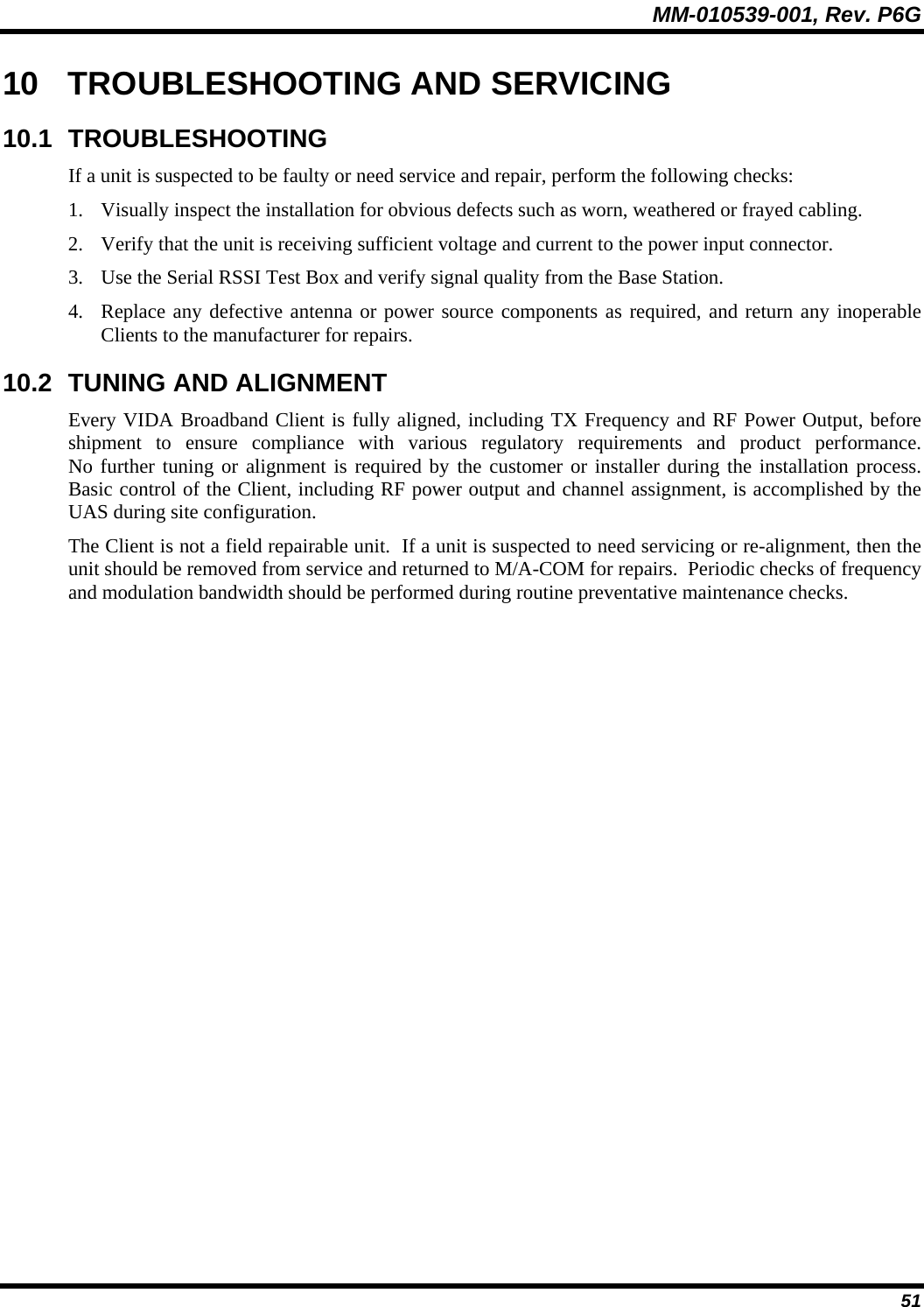
![MM-010539-001, Rev. P6G 56 3. The load bar (oriented so that the cable notch is aligned with the contacts) must be inserted into the RJ-45 plug until it butts against the mating feature of the RJ-45 plug, and the conductors are bottomed on the wire circuits. The cable jacket must be against the cable notch after the load bar is fully seated. The conductors must not be exposed between the cable jacket and cable notch. The ends of the conductors must be clearly visible through the front of the RJ-45 plug. See Figure 11-4, Detail C. If the conductors do not bottom on the wire circuits, they must be re-trimmed (after removing the load bar/cable assembly from the RJ-45 plug), and re-inserted into the RJ-45 plug. If the conductors are too short, the cable must be re-stripped. 4. The RJ-45 plug must be terminated to the cable according to the instructions included with the tooling. 11.1.5 Assembly Assemble the RJ-45 connector into the plug assembly using the following procedures: 1. Align the locking tab of the RJ-45 plug with the wide slot at the front (end opposite the cable fitting) of the plug assembly. See Figure 11-5, Detail A. 2. Depress the locking tab, and insert the RJ-45 plug into the plug assembly. Gently pull the cable until the RJ-45 plug is fully seated. There should be approximately 12.7 mm [.50 in.] of the RJ-45 plug protruding from the front of the plug assembly. See Figure 11-5, Detail B. CAUTION To avoid damage to the connection, the cable must be pulled GENTLY when seating the RJ-45 plug. 3. While holding the RJ-45 plug in position, rotate the cable fitting as shown in Figure 11-5, Detail B until tightened to a torque of 1.13 N–m [10 lbf–in.]. The given torque must be met in order for the cable fitting to seal the plug at the cable end. Figure 11-5: Assembly Detail](https://usermanual.wiki/HARRIS/VIDA-BB-CL.Manual/User-Guide-779005-Page-56.png)
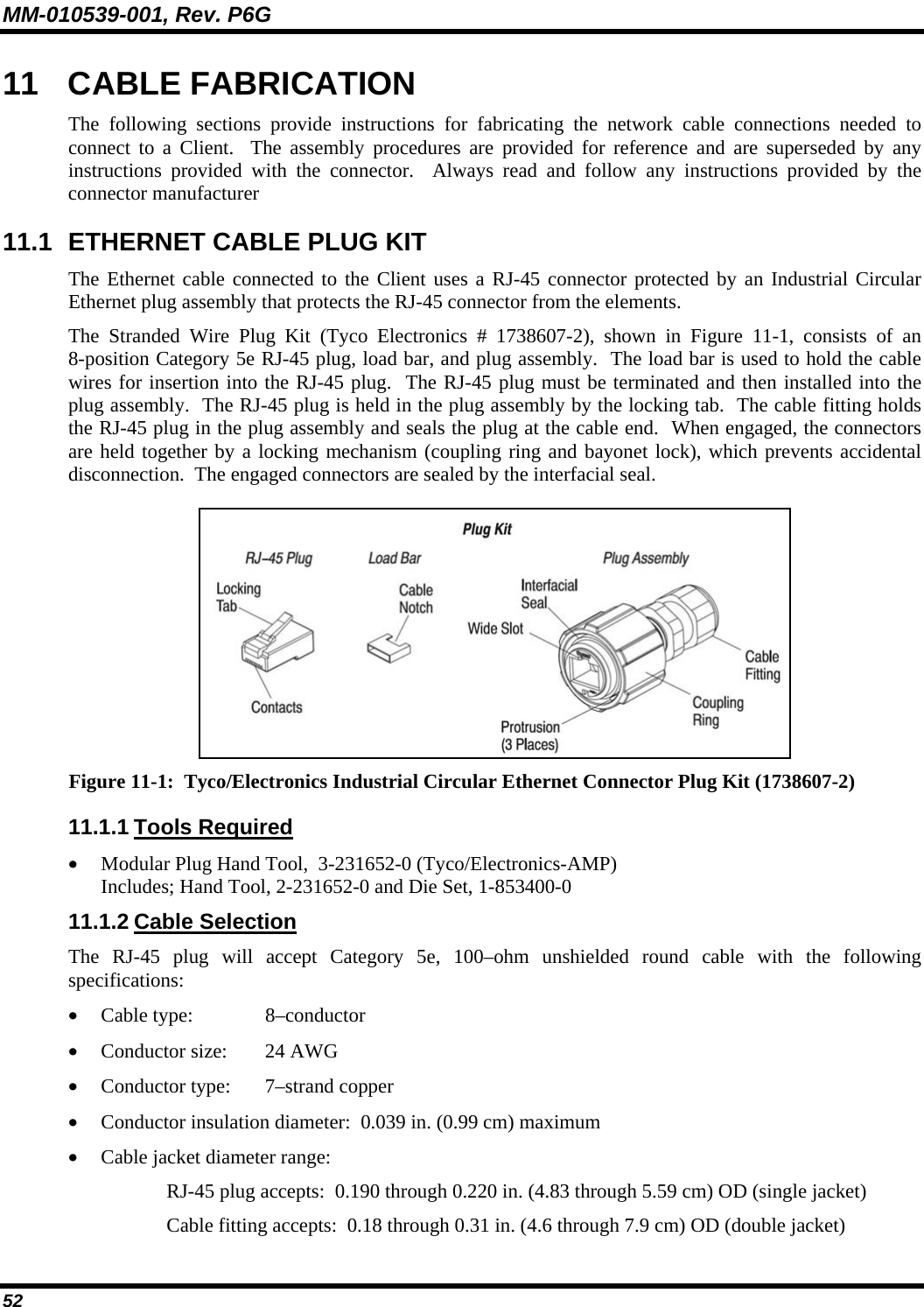
![MM-010539-001, Rev. P6G 58 4. Using shears, cut the strength members and filler flush with the jacket. 5. Using the template provided in the connector kit, mark both the 2.0mm jacketed subunits at the 27mm mark and the 8mm able slit mark. 6. Remove the jacket of each subunit to the 27mm mark with a strip tool. 7. Using a strip template, mark each 900 mm buffer at15.5mm 8. Using a sharp scissors, carefully cut two slits (8mm long) on each jacket. Using a buffer stripper, strip off the buffer in at least three pieces. Using a clean, lint–free cloth (soaked in alcohol), remove any residue from the fiber. 9. Carefully fan back the jacket and strength members, then slide the eyelet over the strength members as shown in Figure 8. 10. After the fiber has been inserted into the connector ferrule, carefully slide the eyelet rearward to unfurl the slit jacket and strength members. Uniformly distribute the aramid and position the slit jacket over the rear body. 11. While holding the connector, push the eyelet forward. 12. Using Tyco Electronics PRO–CRIMPER hand tool and crimping die set 58424–1, crimp the eyelet onto the strength members and jacket. 13. Snap the connectors into the duplex clip. 14. Place the connectors in the plug assembly. 15. Depress both latches and push the connectors into the plug assembly until it bottoms. You will hear an audible “click.” 16. Using two 19mm wrenches, tighten the cable fitting to 0.68 –– 0.90 N–m [6.0 –– 8.0 –in–lbs]. 11-7: Fiber Optic Connector Assembly](https://usermanual.wiki/HARRIS/VIDA-BB-CL.Manual/User-Guide-779005-Page-58.png)