Hawking Technologies HSB1 802.11b/g Adjustable WiFi Signal Booster User Manual HWBA54G Manual Final

Hawking Technologies, Inc. 802.11b/g Adjustable WiFi Signal Booster HWBA54G Manual Final

Contents

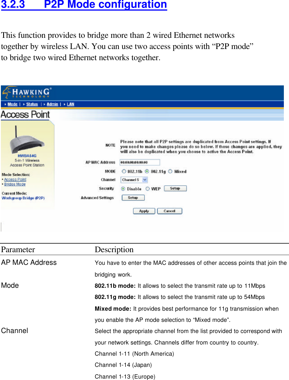
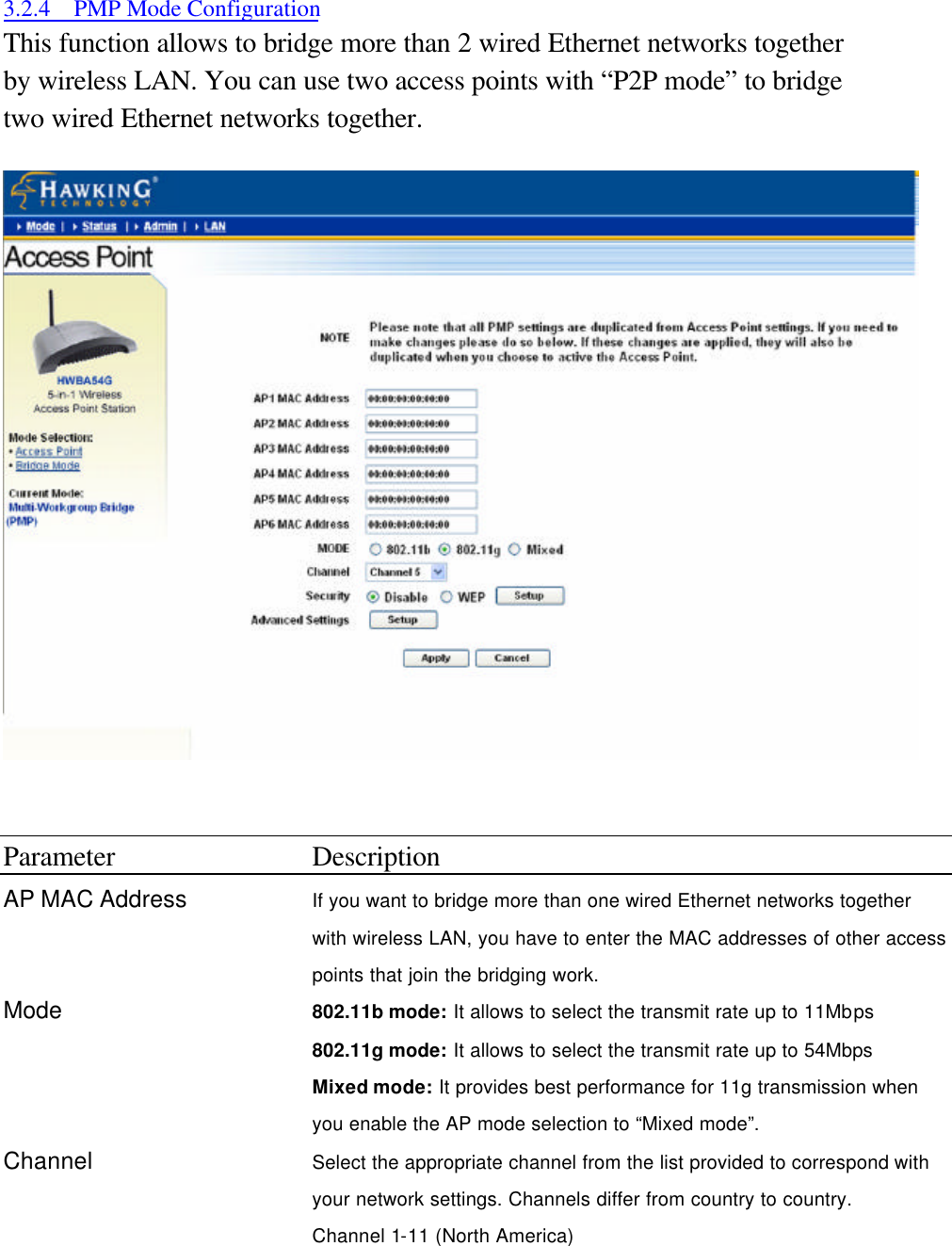
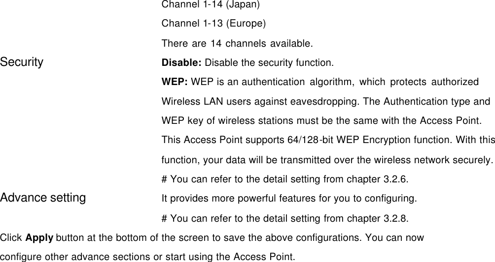
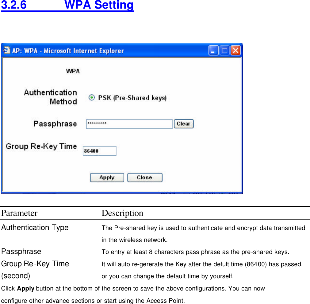
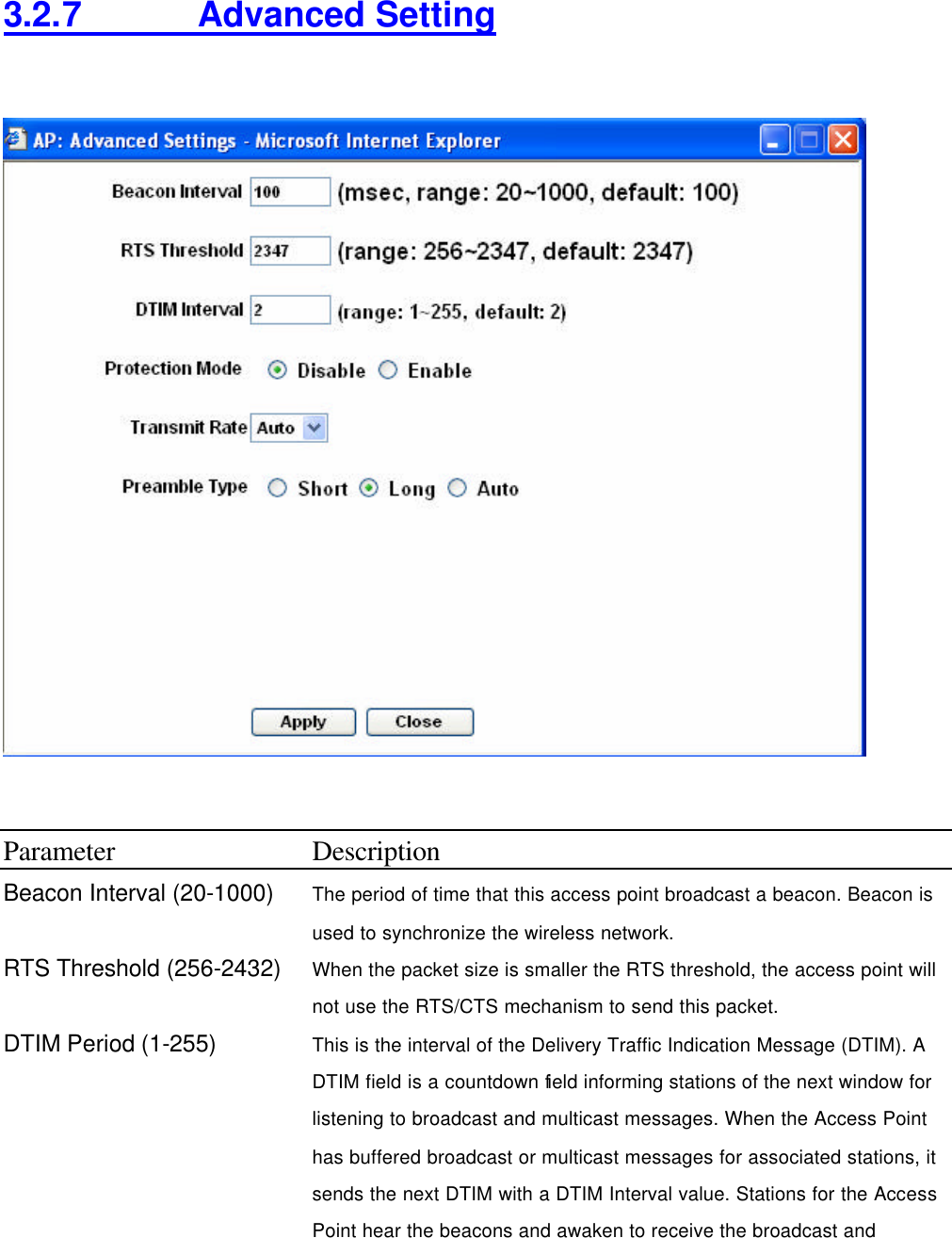
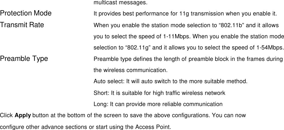
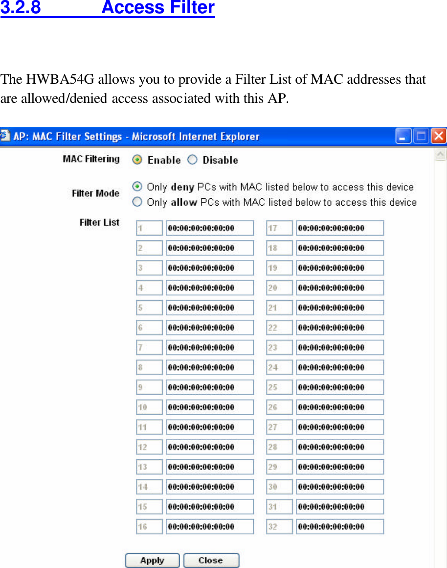
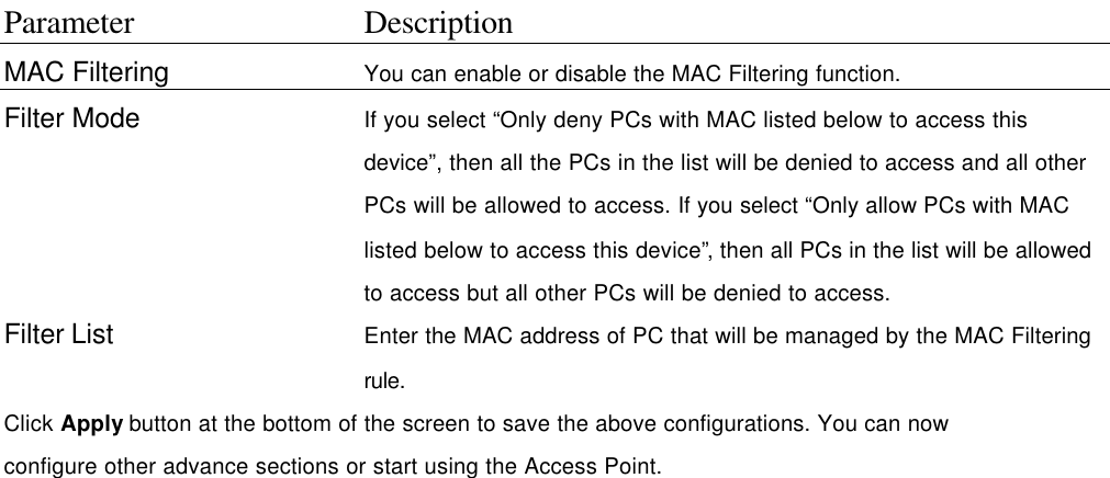
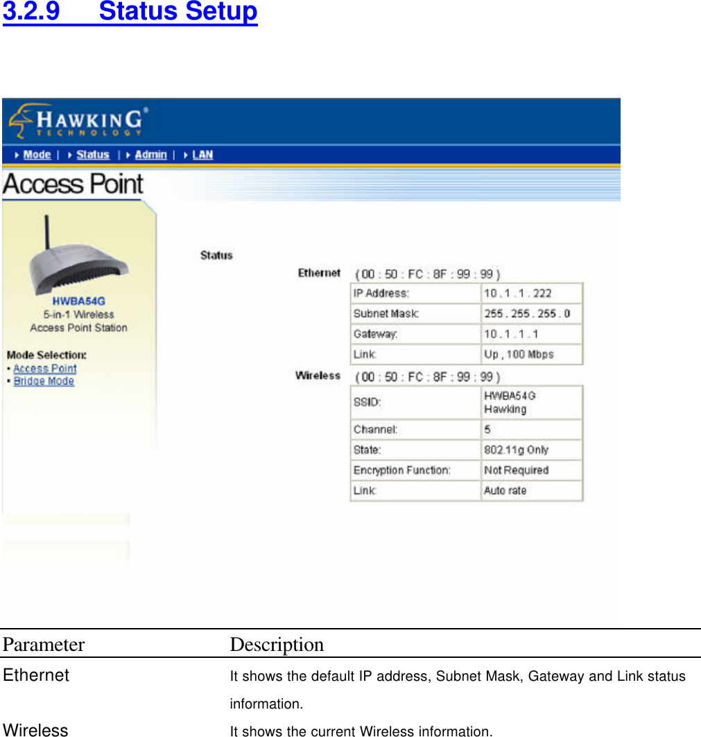
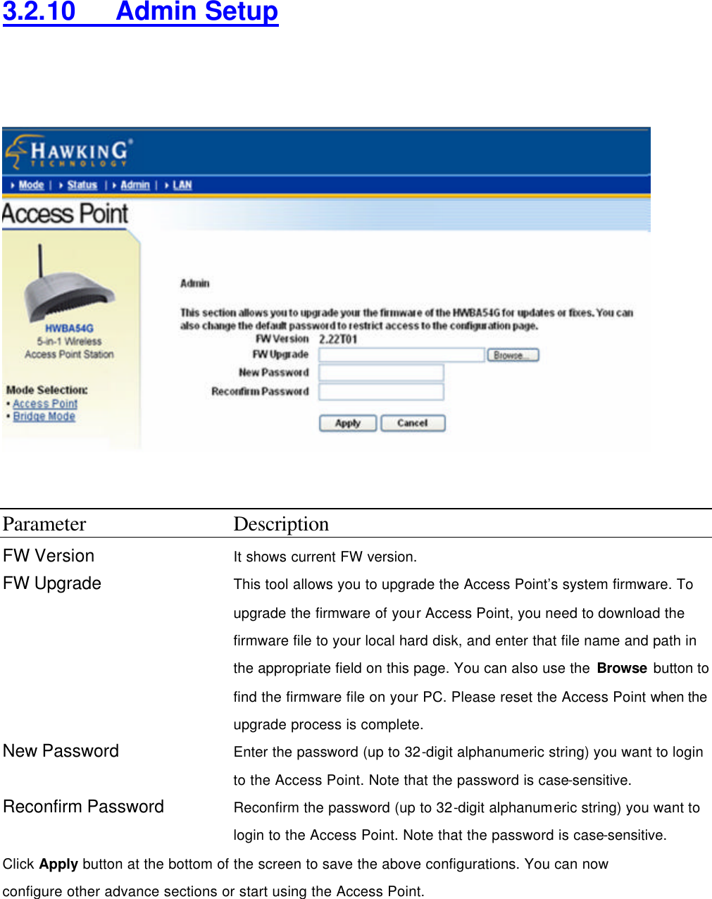
CRN 25109 user manual for access point
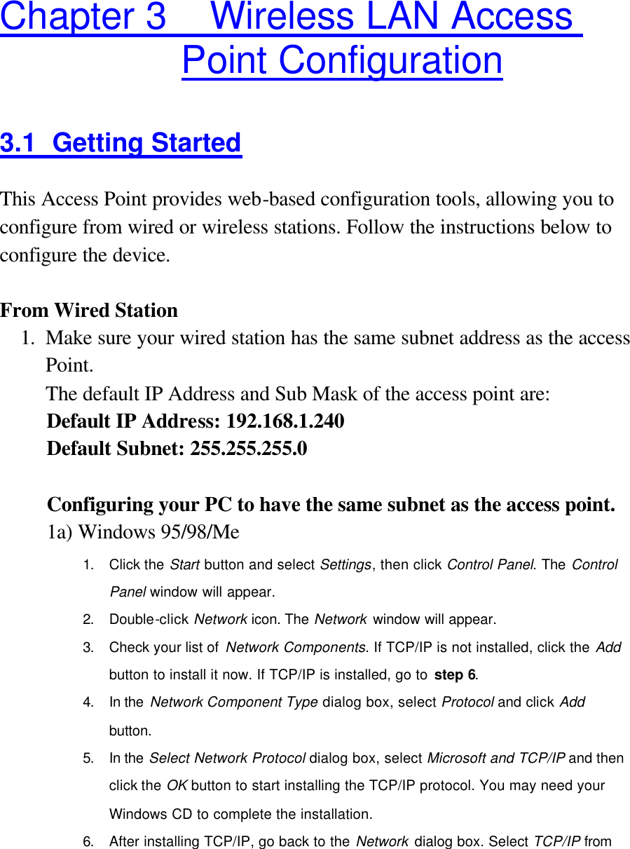
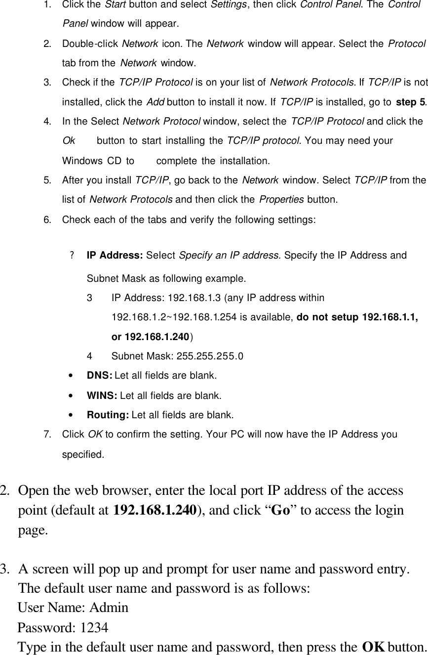
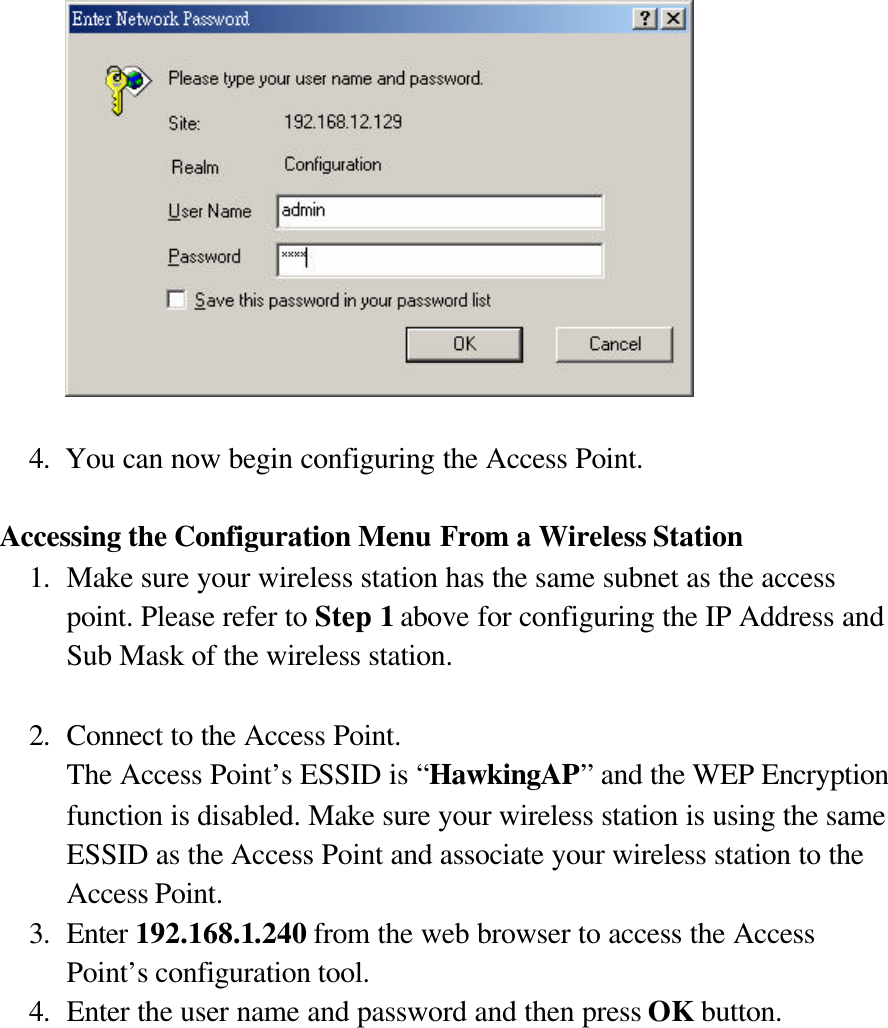
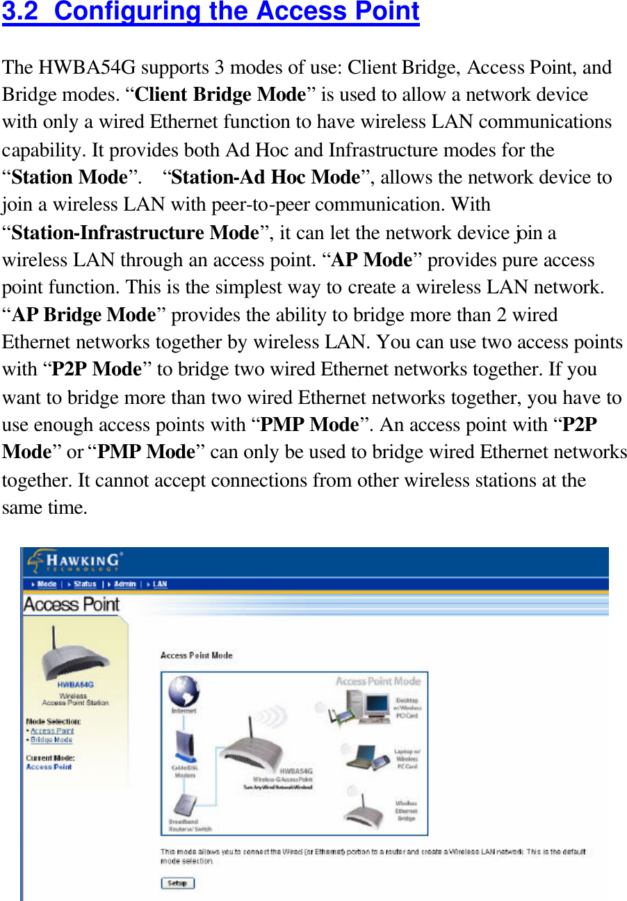
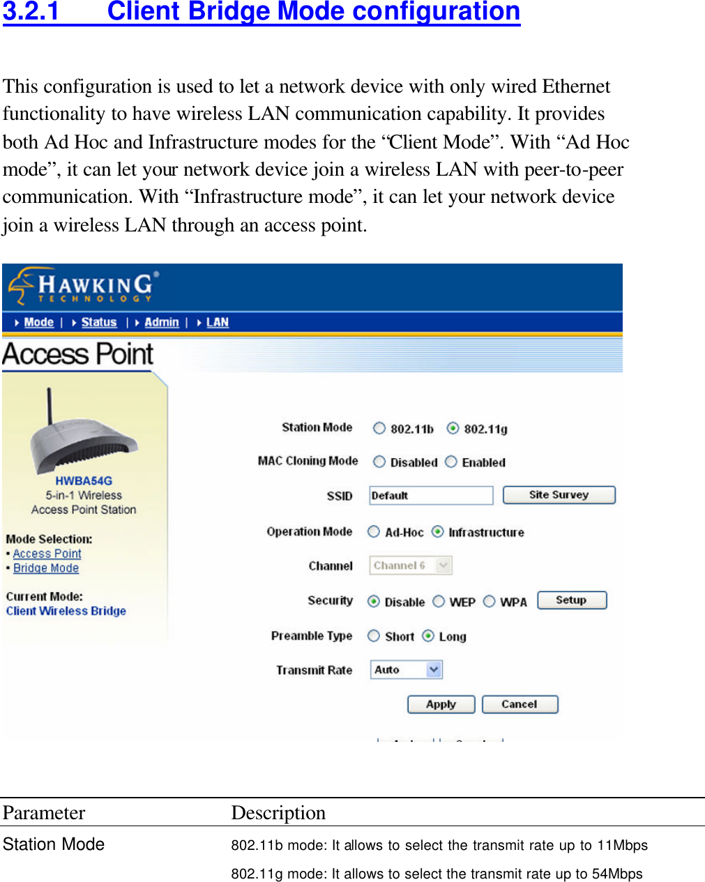
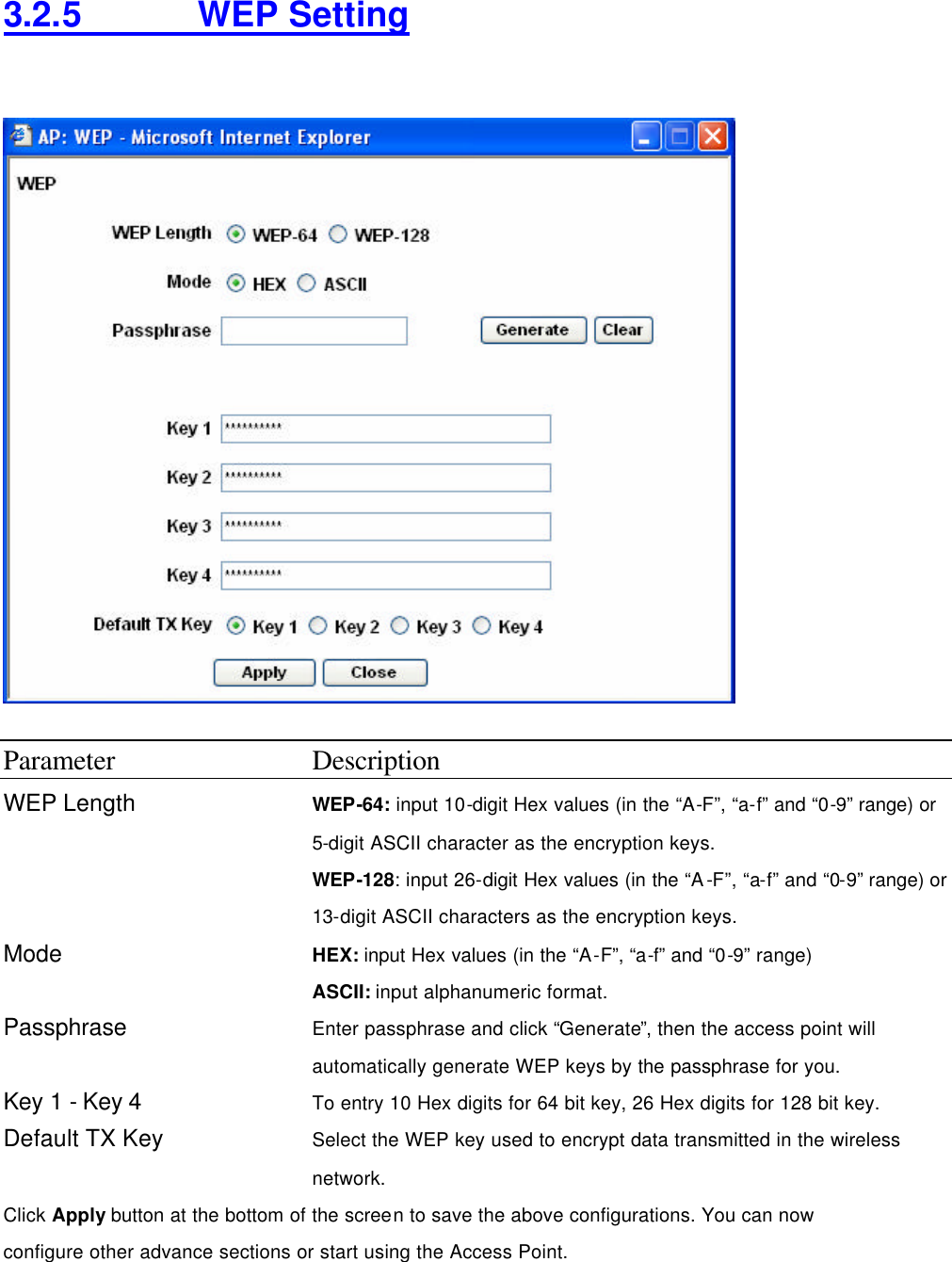
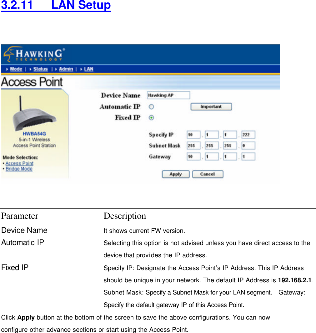
   CE MARK WARNING This is a Class B product. In a domestic environment, this product may cause radio interference, in which case the user may be required to take adequate measures.  LIMITED WARRANTY  Hawking Technology guarantees that every HWBA54G Wireless-G AP / Bridge is free from physical defects in material and workmanship under normal use for two (2) years from the date of purchase.  If the product proves defective during this two-year warranty period, call Hawking Customer Service in order to obtain a Return Authorization number.  Warranty is for repair or replacement only.  Hawking Technology does not issue any refunds.  BE SURE TO HAVE YOUR PROOF OF PURCHASE.  RETURN REQUESTS CAN NOT BE PROCESSED WITHOUT PROOF OF PURCHASE.  When returning a product, mark the Return Authorization number clearly on the outside of the package and include your original proof of purchase. IN NO EVEN SHALL HAWKING TECHNOLOGY’S LIABILTY EXCEED THE PRICE PAID FOR THE PRODUCT FROM DIRECT, INDIRECT, SPECIAL, INCIDENTAL OR CONSEQUENTIAL DAMAGES RESULTING FROM THE USE OF THE PRODUCT, ITS ACCOMPANYING SOFTWARE OR ITS DOCUMENTATION.  Hawking Technology makes no warranty or representation, expressed, implied or statutory, with respect to its products or the contents or use of this documentation and all accompanying software, and specifically disclaims its quality, performance, merchantability, or fitness for any particular purpose.  Hawking Technology reserves the right to revise or updates its products, software, or documentation without obligation to notify any individual or entity.  Please direct all inquiries to:techsupport@hawkingtech.com   TRADEMARKS AND COPYRIGHT  Windows 95/98/ME and Windows NT/2000/XP are registered trademarks of Microsoft Corp. All other brands and product names are trademarks of their respective companies. No part of this publication may be reproduced in any form or by any means or used to make any derivative (such as translation, transformation or adaptation) without the express written consent of the manufacturer as stipulated by the United States Copyright Act of 1976. FCC WARNING  This equipment has been tested and found to comply with the regulations for a Class B digital device, pursuant to Part 15 of the FCC Rules. These limits are designed to provide reasonable protection against harmful interference when the equipment is operated in a commercial environment. This equipment generates, uses, and can radiate radio frequency energy and, if not installed and used in accordance with this user’s guide, may cause harmful interference to radio communications. Operation of this equipment in a residential area is likely to cause harmful interference, in which case the user will be required to correct the interference at his/her own expense.
  Table of Contents  Chapter 1 Introduction...................................................................................1 1.1 Package Contents ................................................................................... 2 1.2 Features ................................................................................................. 2 1.3 Specifications......................................................................................... 2 1.4 Physical Description............................................................................... 3 Chapter 2 Wireless LAN Access Point Connection...................................5 Chapter 3 Wireless LAN Access Point Configuration..............................6 3.1 Getting Started ....................................................................................... 6 3.2 Configuring the Access Point.................................................................11 3.2.1  Client Mode configuration.................................................................................12 3.2.2  AP Mode configuration......................................................................................15 3.2.3  P2P Mode configuration....................................................................................20 3.2.4   PMP Mode configuration.................................................................................21 3.2.5     WEP Setting..................................................................................................23 3.2.6     WPA Setting.................................................................................................25 3.2.7     Advanced Setting..........................................................................................26 3.2.8     Access Filter .................................................................................................27 3.2.9     Status Setup ..................................................................................................29 3.2.10    Admin Setup .................................................................................................30 3.2.11    LAN Setup ....................................................................................................32 Charpter 4 Troubleshooting ........................................................................33
Chapter 1 Introduction Thank you for purchasing the Hawking Technologies Hi-Speed 54M Wireless-G Access Point and Ethernet Bridge. The HWBA54G is compliant with the IEEE 802.11g/b wireless standards.    The Hi-Speed 54G Wireless AP/Bridge utilizes the highest wireless security standards (WPA) to protect your network from outside intruders, including WPA-PSK, WEP, ESSID and MAC address filter functions. With ESSID authentication, WPA-PSK, 64-/128-bit WEP encryption and MAC address filtering, unauthorized outside access into your wireless network is prevented.  The unique multi-function feature of the HWBA54G puts three solutions into one compact unit, saving you time and money.  You may setup your HWBA54G as a Wireless Access Point to provide wireless access to any wired network or you may choose to set up your device as an Ethernet Bridge to make any Ethernet-ready device wireless.  The Hi-Speed 54G Wireless AP/Bridge can also function as a wireless repeater to extend your wireless network range.  The HWBA54G’s dipole antenna is detachable by connecting to a RP-SMA connector. Users can attach an optional Hawking Technologies Hi-Gain antenna to the connector for better network range and signal quality.
1.1 Package Contents The HWBA54G includes the following items: l One HWBA54G Access Point/Bridge l One Power Adapter l One Quick Installation Guide l One Setup CD l One Dipole Antenna  1.2 Features l Complies with the IEEE 802.11g/b wireless standards. l Multiple Functions: Access Point, Ethernet Bridge, Workgroup Bridge. l High speed data rates: 54, 48, 36, 24, 18, 12, 11, 5.5, 2 and 1Mbps network speeds.   l Seamlessly integrates wireless and wired Ethernet LAN networks. l Auto rate fallback in case of obstacles or interferences.   l Provide 64/128-bit WEP Data Encryption security and the latest WPA Security for protected wireless data transmissions. l Supports Web-based configuration.    1.3 Specifications l Standards: IEEE 802.11g/b (Wireless), IEEE 802.3 (Wired) l Data Rate: 54/48/36/24/18/12/11/5.5/2/1Mbps auto fallback l Security: 64/128-bit WEP Data Encryption, WPA l Frequency Band: 2.400~2.4835GHz (Industrial Scientific Medical Band) l Antenna: External detachable dipole antenna (with RP-SMA
connector) l Connectors: 10/100Mbps RJ-45 x 1 l Power: 12VDC, 0.5A l Transmit Power: 16dBm (Typical) l LEDs: Power, LAN Link/Activity, Wireless Activity l Dimension: 30(H) x 127(W) x 87(D) mm   l Temperature:   u Operating: 32~131°F (0~55°C) u Storage: -4~158°F(-20~70°C) l Humidity: 10-90% (Noncondensing)
1.4 Physical Description Front Panel Located on the HWBA54G’s front panel are LED status lights that inform you of the unit’s current status. Below is an explanation of each LED.
Front LED Panel  LED Color Status Description Power Green Lit Power is supplied.     Off No Power.        Wireless Activity Green Flash Antenna is transmitting or receiving data.     Off Antenna is not transmitting or receiving data.        LAN Link/Activity Green On A valid link is established.     Flash It is transmitting or receiving data.     Off No link is established.  Back Panel Connectors  1 Antenna Connector This round connection has a standard Reverse SMA connector where any Reverse SMA-compatible antenna can be connected to the Access Point.  2 DC Adapter Port Insert the power jack of the power adapter into this port.  3 LAN Port The Access Point’s LAN port is where you connect to your network devices.    4 Reset The Reset button allows you to do one of two things.  1) If problems occur with your Access Point, pressing the reset button with a pencil tip (for less than 5 seconds) will reboot the device,
keeping your original configurations intact. 2) If problems continue to persist or you have forgotten your password, pressing the reset button for more than 5 seconds will reset the device back to its factory default settings.   (Warning: your original configurations will be replaced with the factory default settings).
Chapter 2 Wireless LAN Access Point Connection 1. Choosing a location for the access point.   Usually, the best place for the access point is at the center of your wireless network, with line of straight to all your wireless clients.  2. Adjust the antenna.  Usually the higher the antenna is placed, the better your performance will    be.    3. Connect the access point to your local area network (LAN). Connect an Ethernet cable to the Ethernet port of the access point, and the other end to a hub or switch. (If you are using a straight Ethernet cable, make sure the II-X button is switched right; the other way for Cross Ethernet cable.)  4. Power on the device.   Connect the supplied AC power adapter to the access point’s power port and the other end to a wall outlet.  (Note: Use only the included power adapter for the Access Point. Using a different adapter may cause damage to the product.)   The Hardware Installation is now complete.   Please follow the steps below to configure the Access Point.
 Chapter 3    Wireless LAN Access Point Configuration 3.1 Getting Started This Access Point provides web-based configuration tools, allowing you to configure from wired or wireless stations. Follow the instructions below to configure the device.  From Wired Station 1. Make sure your wired station has the same subnet address as the access Point.   The default IP Address and Sub Mask of the access point are: Default IP Address: 192.168.1.240 Default Subnet: 255.255.255.0  Configuring your PC to have the same subnet as the access point.   1a) Windows 95/98/Me 1. Click the Start button and select Settings, then click Control Panel. The Control Panel window will appear. 2. Double-click Network icon. The Network window will appear. 3. Check your list of Network Components. If TCP/IP is not installed, click the Add button to install it now. If TCP/IP is installed, go to step 6. 4. In the Network Component Type dialog box, select Protocol and click Add button. 5. In the Select Network Protocol dialog box, select Microsoft and TCP/IP and then click the OK button to start installing the TCP/IP protocol. You may need your Windows CD to complete the installation. 6. After installing TCP/IP, go back to the Network dialog box. Select TCP/IP from
the list of     Network Components and then click the Properties button. 7. Check each of the tabs and verify the following settings: ? Bindings: Check Client for Microsoft Networks and File and printer sharing for Microsoft Networks. ? Gateway: All fields are blank. ? DNS Configuration: Select Disable DNS. ? WINS Configuration: Select Disable WINS Resolution.  ? IP Address: Select Specify an IP Address. Specify the IP Address and Subnet Mask as following example. 1 IP Address: 192.168.1.3 (any IP address within 192.168.2.2~192.168.2.254 is available, do not setup 192.168.2.1) 2 Subnet Mask: 255.255.255.0 8. Reboot the PC. Your PC will now have the IP Address you specified.  1b) Windows 2000 1. Click the Start button and select Settings, then click Control Panel. The Control Panel window will appear. 2. Double-click Network and Dial-up Connections icon. In the Network and Dial-up     Connection window, double-click Local Area Connection icon. The Local Area Connection window will appear. 3. In the Local Area Connection window, click the Properties button. 4. Check your list of Network Components. You should see Internet Protocol [TCP/IP] on     your list. Select it and click the Properties button. 5. In the Internet Protocol (TCP/IP) Properties window, select Use the following IP address and specify the IP Address and Subnet mask as following. ? IP Address: 192.168.1.3 (any IP address within 192.168.1.2~192.168.1.239 is available, do not setup 192.168.1.1 or 192.168.1.240) ? Subnet Mask: 255.255.255.0 6. Click OK to confirm the setting. Your PC will now have the IP Address you specified.  1c) Windows NT
1. Click the Start button and select Settings, then click Control Panel. The Control Panel window will appear. 2. Double-click Network icon. The Network window will appear. Select the Protocol tab from the Network window. 3. Check if the TCP/IP Protocol is on your list of Network Protocols. If TCP/IP is not installed, click the Add button to install it now. If TCP/IP is installed, go to step 5. 4. In the Select Network Protocol window, select the TCP/IP Protocol and click the Ok     button to start installing the TCP/IP protocol. You may need your Windows CD to     complete the installation. 5. After you install TCP/IP, go back to the Network window. Select TCP/IP from the list of Network Protocols and then click the Properties button. 6. Check each of the tabs and verify the following settings:  ? IP Address: Select Specify an IP address. Specify the IP Address and Subnet Mask as following example. 3 IP Address: 192.168.1.3 (any IP address within 192.168.1.2~192.168.1.254 is available, do not setup 192.168.1.1, or 192.168.1.240) 4 Subnet Mask: 255.255.255.0 • DNS: Let all fields are blank. • WINS: Let all fields are blank. • Routing: Let all fields are blank. 7. Click OK to confirm the setting. Your PC will now have the IP Address you specified.  2. Open the web browser, enter the local port IP address of the access point (default at 192.168.1.240), and click “Go” to access the login page.  3. A screen will pop up and prompt for user name and password entry. The default user name and password is as follows: User Name: Admin Password: 1234 Type in the default user name and password, then press the OK button.
   4. You can now begin configuring the Access Point.  Accessing the Configuration Menu From a Wireless Station 1. Make sure your wireless station has the same subnet as the access point. Please refer to Step 1 above for configuring the IP Address and Sub Mask of the wireless station.  2. Connect to the Access Point. The Access Point’s ESSID is “HawkingAP” and the WEP Encryption function is disabled. Make sure your wireless station is using the same ESSID as the Access Point and associate your wireless station to the Access Point. 3. Enter 192.168.1.240 from the web browser to access the Access Point’s configuration tool. 4. Enter the user name and password and then press OK button.
3.2 Configuring the Access Point The HWBA54G supports 3 modes of use: Client Bridge, Access Point, and Bridge modes. “Client Bridge Mode” is used to allow a network device with only a wired Ethernet function to have wireless LAN communications capability. It provides both Ad Hoc and Infrastructure modes for the “Station Mode”.  “Station-Ad Hoc Mode”, allows the network device to join a wireless LAN with peer-to-peer communication. With “Station-Infrastructure Mode”, it can let the network device join a wireless LAN through an access point. “AP Mode” provides pure access point function. This is the simplest way to create a wireless LAN network. “AP Bridge Mode” provides the ability to bridge more than 2 wired Ethernet networks together by wireless LAN. You can use two access points with “P2P Mode” to bridge two wired Ethernet networks together. If you want to bridge more than two wired Ethernet networks together, you have to use enough access points with “PMP Mode”. An access point with “P2P Mode” or “PMP Mode” can only be used to bridge wired Ethernet networks together. It cannot accept connections from other wireless stations at the same time.
 3.2.1 Client Bridge Mode configuration This configuration is used to let a network device with only wired Ethernet functionality to have wireless LAN communication capability. It provides both Ad Hoc and Infrastructure modes for the “Client Mode”. With “Ad Hoc mode”, it can let your network device join a wireless LAN with peer-to-peer communication. With “Infrastructure mode”, it can let your network device join a wireless LAN through an access point.     Parameter Description Station Mode 802.11b mode: It allows to select the transmit rate up to 11Mbps  802.11g mode: It allows to select the transmit rate up to 54Mbps
MAC Cloning Mode Disabled: It will use it’s own MAC address to access the wireless LAN. Enabled: It will use PC’s MAC address to access the wireless LAN. SSID The SSID (up to 32 printable ASCII characters) is the unique name identified in a WLAN. The ID prevents the unintentional merging of two co-located WLANs. Please make sure that the SSID of all stations in the same WLAN network are the same. The default SSID is “default”. Site Survey Click “Site Survey” button, then a “Wireless Site Survey Table” will pop up. It will list all available access points near by. You can select one access point in the table and it will join wireless LAN through this access point. Operation Mode AD-Hoc: It can let your network device join a wireless LAN with peer-to-peer communication. Infrastructure:  It can let your network device join a wireless LAN through an access point. Channel Select the appropriate channel from the list provided to correspond with your network settings. Channels differ from country to country. Channel 1-11 (North America) Channel 1-14 (Japan) Channel 1-13 (Europe) There are 14 channels available.   Security   Disable: Disable the security function. WEP: WEP is an authentication algorithm, which protects authorized             Wireless LAN users against eavesdropping. The Authentication type and WEP key of wireless stations must be the same with the Access Point. This Access Point supports 64/128-bit WEP Encryption function. With this function, your data will be transmitted over the wireless network securely. # You can refer to the detail setting from chapter 3.2.6. WPA: You can use a pre-shared key to authenticate wireless stations and encrypt data during communication. When you enabled WPA mode, you can not use WEP encryption.   # You can refer to the detail setting from chapter 3.2.7. Preamble Type Preamble type defines the length of preamble block in the frames during the wireless communication. Auto select: It will auto switch to the more suitable method.
Short: It is suitable for high traffic wireless network Long: It can provide more reliable communication   Transmit Rate When you enable the station mode selection to “802.11b” and it allows you to select the speed of 1-11Mbps. When you enable the station mode selection to “802.11g” and it allows you to select the speed of 1-54Mbps.  Click Apply button at the bottom of the screen to save the above configurations. You can now configure other advance sections or start using the Access Point.    Site Survey table:  When this access point is in “Client-Infrastructure mode”, it should associate with an access point and connect to your wireless LAN through the associated access point. “Wireless Site Survey” searches for all available access points near by. You can select one access point listed in this table.
3.2.2 AP Mode configuration   This Access Point supports AP modes. “Access Point Mode” provides pure access point function. The simplest way to build up a wireless LAN is to use “AP Mode”.  Access Point Mode provides wireless access to a wired network.    Parameter Description Mode 802.11b mode: It allows to select the transmit rate up to 11Mbps 802.11g mode: It allows to select the transmit rate up to 54Mbps Mixed mode: It provides best performance for 11g transmission when you enable the AP mode selection to “Mixed mode”. SSID The SSID (up to 32 printable ASCII characters) is the unique name identified in a WLAN. The ID prevents the unintentional merging of two co-located WLANs. Please make sure that the SSID of all stations in the same WLAN network are the same. The default SSID is “default”.
Broadcast SSID It will respond to Broadcast SSID requests. If you enable this function, every wireless station located within the coverage of this access point can discover this access point easily. If you are building a public wireless network, enabling this feature is recommended. Disabling "Response to Broadcast ESSID requests" can provide better security. Channel Select the appropriate channel from the list provided to correspond with your network settings. Channels differ from country to country. Channel 1-11 (North America) Channel 1-14 (Japan) Channel 1-13 (Europe) There are 14 channels available.   Security   Disable: Disable the security function. WEP: WEP is an authentication algorithm, which protects authorized             Wireless LAN users against eavesdropping. The Authentication type and WEP key of wireless stations must be the same with the Access Point. This Access Point supports 64/128-bit WEP Encryption function. With this function, your data will be transmitted over the wireless network securely. # You can refer to the detail setting from chapter 3.2.6. WPA: You can use a pre-shared key to authenticate wireless stations and encrypt data during communication. When you enabled WPA mode, you can not use WEP encryption.   # You can refer to the detail setting from chapter 3.2.7. Advance setting It provides more powerful features for you to configuring. # You can refer to the detail setting from chapter 3.2.8. Access Filter This Access Point allows you to provide a Filter List of MAC addresses that are allowed associating with this AP. # You can refer to the detail setting from chapter 3.2.9. Click Apply button at the bottom of the screen to save the above configurations. You can now configure other advance sections or start using the Access Point.
3.2.3 P2P Mode configuration This function provides to bridge more than 2 wired Ethernet networks together by wireless LAN. You can use two access points with “P2P mode” to bridge two wired Ethernet networks together.    Parameter Description AP MAC Address You have to enter the MAC addresses of other access points that join the bridging work. Mode 802.11b mode: It allows to select the transmit rate up to 11Mbps 802.11g mode: It allows to select the transmit rate up to 54Mbps Mixed mode: It provides best performance for 11g transmission when you enable the AP mode selection to “Mixed mode”. Channel Select the appropriate channel from the list provided to correspond with your network settings. Channels differ from country to country. Channel 1-11 (North America) Channel 1-14 (Japan) Channel 1-13 (Europe)
There are 14 channels available.   Security   Disable: Disable the security function. WEP: WEP is an authentication algorithm, which protects authorized             Wireless LAN users against eavesdropping. The Authentication type and WEP key of wireless stations must be the same with the Access Point. This Access Point supports 64/128-bit WEP Encryption function. With this function, your data will be transmitted over the wireless network securely. # You can refer to the detail setting from chapter 3.2.6. Advance setting It provides more powerful features for you to configuring. # You can refer to the detail setting from chapter 3.2.8. Click Apply button at the bottom of the screen to save the above configurations. You can now configure other advance sections or start using the Access Point.
3.2.4  PMP Mode Configuration This function allows to bridge more than 2 wired Ethernet networks together by wireless LAN. You can use two access points with “P2P mode” to bridge two wired Ethernet networks together.    Parameter Description AP MAC Address If you want to bridge more than one wired Ethernet networks together with wireless LAN, you have to enter the MAC addresses of other access points that join the bridging work.   Mode 802.11b mode: It allows to select the transmit rate up to 11Mbps 802.11g mode: It allows to select the transmit rate up to 54Mbps Mixed mode: It provides best performance for 11g transmission when you enable the AP mode selection to “Mixed mode”. Channel Select the appropriate channel from the list provided to correspond with your network settings. Channels differ from country to country. Channel 1-11 (North America)
Channel 1-14 (Japan) Channel 1-13 (Europe) There are 14 channels available.   Security   Disable: Disable the security function. WEP: WEP is an authentication algorithm, which protects authorized             Wireless LAN users against eavesdropping. The Authentication type and WEP key of wireless stations must be the same with the Access Point. This Access Point supports 64/128-bit WEP Encryption function. With this function, your data will be transmitted over the wireless network securely. # You can refer to the detail setting from chapter 3.2.6. Advance setting It provides more powerful features for you to configuring. # You can refer to the detail setting from chapter 3.2.8. Click Apply button at the bottom of the screen to save the above configurations. You can now configure other advance sections or start using the Access Point.
3.2.5    WEP Setting   Parameter Description WEP Length WEP-64: input 10-digit Hex values (in the “A-F”, “a-f” and “0-9” range) or 5-digit ASCII character as the encryption keys. WEP-128: input 26-digit Hex values (in the “A-F”, “a-f” and “0-9” range) or 13-digit ASCII characters as the encryption keys.   Mode HEX: input Hex values (in the “A-F”, “a-f” and “0-9” range) ASCII: input alphanumeric format.   Passphrase Enter passphrase and click “Generate”, then the access point will automatically generate WEP keys by the passphrase for you. Key 1 - Key 4 To entry 10 Hex digits for 64 bit key, 26 Hex digits for 128 bit key.   Default TX Key Select the WEP key used to encrypt data transmitted in the wireless network. Click Apply button at the bottom of the screen to save the above configurations. You can now configure other advance sections or start using the Access Point.
3.2.6    WPA Setting    Parameter Description Authentication Type The Pre-shared key is used to authenticate and encrypt data transmitted in the wireless network.   Passphrase To entry at least 8 characters pass phrase as the pre-shared keys. Group Re-Key Time (second) It will auto re-gererate the Key after the defult time (86400) has passed, or you can change the default time by yourself.   Click Apply button at the bottom of the screen to save the above configurations. You can now configure other advance sections or start using the Access Point.
3.2.7    Advanced Setting  Parameter Description Beacon Interval (20-1000) The period of time that this access point broadcast a beacon. Beacon is used to synchronize the wireless network.   RTS Threshold (256-2432) When the packet size is smaller the RTS threshold, the access point will not use the RTS/CTS mechanism to send this packet.   DTIM Period (1-255) This is the interval of the Delivery Traffic Indication Message (DTIM). A DTIM field is a countdown field informing stations of the next window for listening to broadcast and multicast messages. When the Access Point has buffered broadcast or multicast messages for associated stations, it sends the next DTIM with a DTIM Interval value. Stations for the Access Point hear the beacons and awaken to receive the broadcast and
multicast messages.   Protection Mode It provides best performance for 11g transmission when you enable it. Transmit Rate When you enable the station mode selection to “802.11b” and it allows you to select the speed of 1-11Mbps. When you enable the station mode selection to “802.11g” and it allows you to select the speed of 1-54Mbps.  Preamble Type Preamble type defines the length of preamble block in the frames during the wireless communication. Auto select: It will auto switch to the more suitable method. Short: It is suitable for high traffic wireless network Long: It can provide more reliable communication   Click Apply button at the bottom of the screen to save the above configurations. You can now configure other advance sections or start using the Access Point.
3.2.8    Access Filter  The HWBA54G allows you to provide a Filter List of MAC addresses that are allowed/denied access associated with this AP.
Parameter Description MAC Filtering   You can enable or disable the MAC Filtering function. Filter Mode   If you select “Only deny PCs with MAC listed below to access this device”, then all the PCs in the list will be denied to access and all other PCs will be allowed to access. If you select “Only allow PCs with MAC listed below to access this device”, then all PCs in the list will be allowed to access but all other PCs will be denied to access. Filter List Enter the MAC address of PC that will be managed by the MAC Filtering rule. Click Apply button at the bottom of the screen to save the above configurations. You can now configure other advance sections or start using the Access Point.
3.2.9   Status Setup   Parameter Description Ethernet It shows the default IP address, Subnet Mask, Gateway and Link status information. Wireless It shows the current Wireless information.
3.2.10   Admin Setup     Parameter Description FW Version It shows current FW version. FW Upgrade This tool allows you to upgrade the Access Point’s system firmware. To upgrade the firmware of your Access Point, you need to download the firmware file to your local hard disk, and enter that file name and path in the appropriate field on this page. You can also use the Browse button to find the firmware file on your PC. Please reset the Access Point when the upgrade process is complete. New Password Enter the password (up to 32-digit alphanumeric string) you want to login to the Access Point. Note that the password is case-sensitive. Reconfirm Password Reconfirm the password (up to 32-digit alphanumeric string) you want to login to the Access Point. Note that the password is case-sensitive. Click Apply button at the bottom of the screen to save the above configurations. You can now configure other advance sections or start using the Access Point.
3.2.11   LAN Setup     Parameter Description Device Name It shows current FW version. Automatic IP Selecting this option is not advised unless you have direct access to the device that provides the IP address. Fixed IP Specify IP: Designate the Access Point’s IP Address. This IP Address should be unique in your network. The default IP Address is 192.168.2.1.  Subnet Mask: Specify a Subnet Mask for your LAN segment.  Gateway: Specify the default gateway IP of this Access Point.   Click Apply button at the bottom of the screen to save the above configurations. You can now configure other advance sections or start using the Access Point.
Chapter4 Troubleshooting This chapter provides solutions to problems usually encountered during the installation and operation of the Access Point.    1. How do I manually find the PC’s IP and MAC Address? 1) In Windows, open the Command Prompt program 2) Type Ipconfig /all and  Enter 1 Your PC’s IP address is the one entitled IP address 2 Your PC’s MAC Address is the one entitled Physical Address  2. What is BSS ID? A group of wireless stations and an Access Point compose a Basic Service Set (BSS). Computers in a BSS must be configured with the same BSSID.  3. What is ESSID? An Infrastructure configuration could also support roaming capability for mobile workers. More than one BSS can be configured as an Extended Service Set (ESS). Users within an ESS could roam freely between BSSs while maintaining a continuous connection to the wireless network stations and the Wireless LAN Access Points.  4. Can data be intercepted while transmitting through the air? WLAN features two-fold protection in security. On the hardware side, as with Direct Sequence Spread Spectrum technology, it has the inherent scrambling security feature. On the software side, the WLAN series offers the encryption function (WEP) to enhance security and access control.  5. What is WEP? WEP stands for Wired Equivalent Privacy, a data privacy mechanism
based on a 64(40)-bit shared key algorithm.  6. What is a MAC Address? The Media Access Control (MAC) address is a unique number assigned by the manufacturer to any Ethernet networking device, such as a network adapter, that allows the network to identify it at the hardware level. For all practical purposes, this number is usually permanent. Unlike IP addresses which can change every time a computer logs on to the network, the MAC address of a device stays the same, making it a valuable identifier for the network.

Navigation menu