Heatcraft Refrigeration Products H Engm0408 Users Manual
H-ENGM0408 EM
H-ENGM0806 to the manual 7716b0a8-f94b-403c-b113-ebbd72203962
2015-02-09
: Heatcraft-Refrigeration-Products Heatcraft-Refrigeration-Products-H-Engm0408-Users-Manual-564768 heatcraft-refrigeration-products-h-engm0408-users-manual-564768 heatcraft-refrigeration-products pdf
Open the PDF directly: View PDF ![]() .
.
Page Count: 44
Commercial Refrigeration
Cooling and Freezing
Load Calculations and Reference Guide
H-ENGM0408, April 2008
(Replaces H-ENGM0806, August 2006)
Engineering Manual
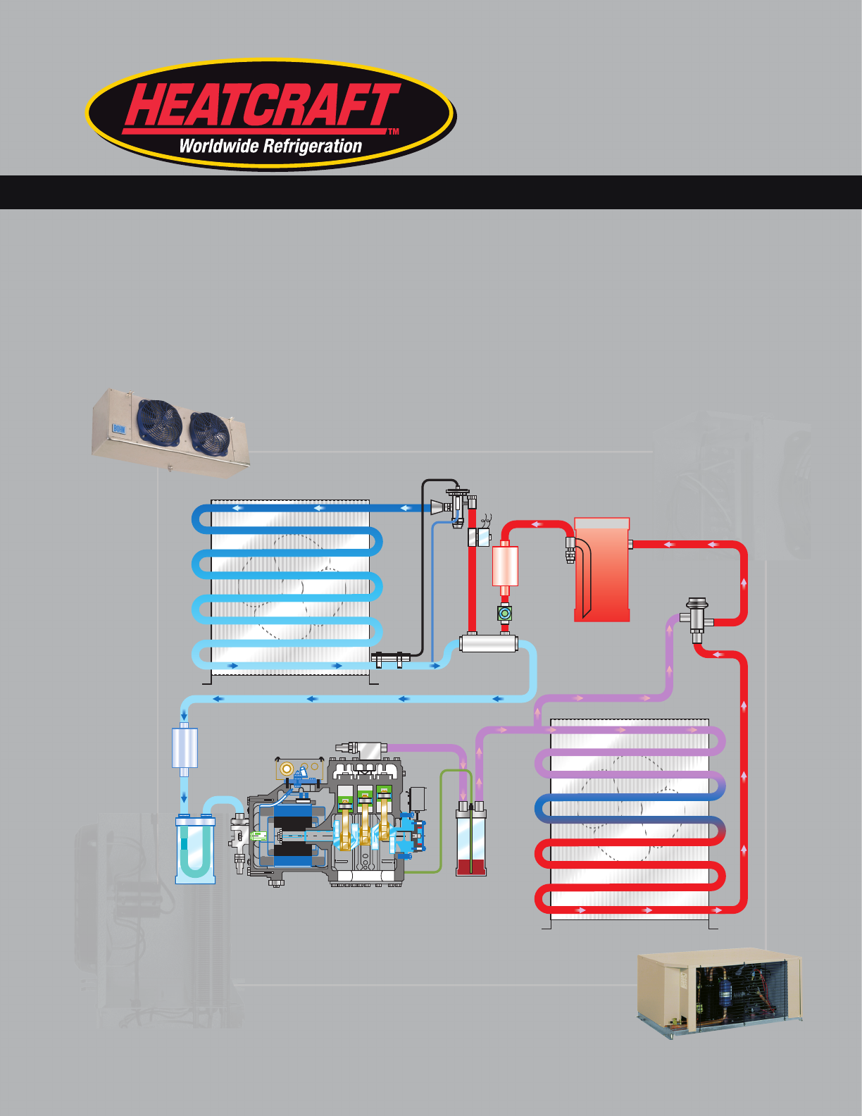
Head Pressure
Control Valve
Oil
Separator
Compressor
Suction
Accumulator
Suction
Filter
Evaporator
Condenser
Liquid Line
Solenoid Valve
Liquid Line
Sight Glass
Receiver
Heat
Exchanger
Filter-
Drier
Expansion
Valve

2
© 2008 Heatcraft Refrigeration Products LLC
www.thecoldstandard.com
www.coldyoucancounton.com
Commercial Refrigeration Parts
™
History of High Performance,
Innovation and Product Selection
Larkin has been the most trusted
brand of refrigeration products for
clean environments since 1928. With
its innovative products, it is uniquely
qualied to meet the needs of
foodservice applications as well as
mission critical applications such as
data centers.
www.interlinkparts.com
www.chandlerref.com
www.larkinproducts.com
Serving the Cold
Storage Industry with
Engineered Solutions
Chandler has been a
leading commercial refrigeration brand since 1933. Its
emphasis on partnership allows customers to give input
during the system design process, resulting in customized
solutions that are precisely engineered to order.
History of Leadership, Service
and Innovation
Bohn has been the
Supermarket Industry’s leading
brand of refrigeration products
since 1946. With an emphasis
on innovation and the
environment, Bohn is the clear
choice for meeting the demanding needs of this industry
both in the United States and globally.
History of Dependability,
Technical Support and
Product Choice
Climate Control is the
brand that revolutionized
convenience store refrigeration in the 1970’s. Its reputation
of dependability and products designed to reduce
installation and operation costs still make it the number one
choice of convenience store owners everywhere.
Right source. Right parts. Right now.
We are your link to a complete line of dependable and certied
commercial refrigeration parts, accessories and innovative electronic
controls. Dependable. Versatile. Courteous. Finally, one simple source
for all of your parts needs from a name you can trust.
®
Refrigeration Equipment References on the World Wide Web
Forward
This edition of Heatcraft Refrigeration Products LLC’s, Engineering
Manual covering Commercial Refrigeration Cooling and Freezing
Load Calculations has been prepared in the form of a condensed
text and reference book.
The theory and principle of modern refrigeration has been
omitted due to the many excellent publications currently available
on these subjects. The purpose of this reference book is to furnish
the engineering, selling and servicing organizations with accurate
and useful data to simplify load calculations.
No attempt has been made to specify a particular make of
equipment. We sincerely hope that our eorts will be a tangible
contribution to our rapidly growing industry.
Table of Contents
Job Survey 4
Refrigeration Load Calculations 4-6
Sample Calculations:
Above 32ºF. (0ºC.) 7-9
Sample Calculations:
Rooms Below 32ºF. (0ºC.) 10-12
Refrigeration Equipment Selection 21
Type of Operation and Air Flow 22
Derating Factors 22
General Guidelines 23
Unit Cooler Coil Placement 24
Sizing of Refrigerant Lines 25-32
Psychrometric Chart 37-39
Glossary of Refrigeration Terms 40
Quick Selection Guide 41
Rapid Load Calculator for Large Coolers & Freezers 43

3
Tables
1. Wall heat loads 13
2. Insulated block K factors 13
3. Allowance for sun eect ............................................................................13
4. Average air changes per 24 hours for storage
rooms above 32ºF. (0ºC.) due to door
openings and inltration 14
5. Average air changes per 24 hours for storage
rooms below 32ºF. (0ºC.) due to door
openings and inltration 14
6. Heat removed in cooling air to storage
room conditions (BTU per Cu. Ft.) 14
7. Storage requirements and properties of
perishable products 15-16
8. Heat of respiration 17
9. Heat loads of keg and bottled beer 18
10. Carcass weights 18
11. Heat equivalent of electric motors 18
12. Heat equivalent of occupancy 18
13. General standards for insulation
thickness in storage rooms 18
14. Heat gain due to operation of battery lift trucks 18
15. Specic heats of various liquids and solids 18
16. Banana room
refrigeration requirement 19
17. Meat cutting or preparation room 19
18. Rapid load selection for back bars 19
19. Refrigeration requirements for hardening
ice cream 19
20. Glass door load 19
21. Summer outside air and ground
temperature design conditions 20
22. Suction and liquid line sizes for R-134A 25, 26
23. Suction and liquid line sizes for R-22 27, 28
24. Suction & liquid line sizes for R-404A, R-507/AZ50 29, 30
25. Pressure drop of liquid refrigerants in
vertical risers 31
26. Equivalent feet of pipe for
valves and ttings 31
27. Remote condenser line sizes for
R-134A, R-22, R-507/AZ50 and R-404A 32
28. L-type tubing– weight of refrigerants in copper
lines of operating systems 33
29. Fahrenheit-Celsius temperature
conversion chart 34
30. Conversion factors 35
31. Electrical formulas 35
32. English conversion factors and data 36
33. English to metric conversion factors 36
Table
No.
Table
No.
page
No.
page
No.

4
Job Survey
The person involved in a heat transfer calculation needs
information in order to predict accurately the heat load on a
refrigerated structure. The more complete the information, the
better the calculation. Good calculations are the rst step in
assuring adequate refrigeration equipment is selected for the
project.
The initial job survey should be as complete as possible and
include the following:
Design Ambient Temperature
This is the ambient surrounding the box necessary for the load
calculations. Another ambient to be considered on air cooled
projects is the one surrounding the condensing unit which will
aect equipment selection.
Storage Temperature and Humidity Requirements
Refrigeration equipment by its nature is a dehumidication
process. We try to minimize or maximize the drying eect of the
equipment by selecting the appropriate Temperature Dierence
(T.D.) between the saturated suction temperature of the
evaporator and the room air. The T.D. selected approximates the
desired relative humidity (see page 21).
Dimensions, Insulation, Type of Construction,
Exposure
This criterion lends itself to well established, straight forward
calculations, but the information while elementary, is often
omitted from the initial job survey. Transmission load for 4”
Styrofoam is double the transmission load for 4” formed in place
urethane.
Inltration or Air Changed Load
Heat, both sensible and latent, enters an enclosure through door
openings whenever the air surrounding the enclosure is warmer
than the box temperature. Knowing the location, size and
number of the door openings and the temperature to which they
are exposed will greatly aid in determining the heat load of the
inltration air.
Product
1. Type - storage requirements
2. Weight
3. Entering temperature
4. Pull down time
Miscellaneous Loads
1. Lights
2. Motors including fan motors, fork lifts, conveyers
3. People
4. Glass doors
Operations
1. Holding cooler or freezer
2. Blast cooling or freezing
3. Preparation, processing or cutting rooms
4. Distribution warehouses
5. Reach-in or walk-in boxes
Unusual Conditions
Electrical Service and Type of Equipment Desired
While not directly aecting refrigeration load calculations,
this is essential in the job survey to select the proper equipment.
Refrigeration Load Calculations
With the initial survey complete, the heat load calculation is
separated into the following main sources of heat for a given 24
hour period:
1. Transmission load
2. Air change load
3. Miscellaneous load
4. Product load
Accuracy
Accuracy in calculation is the rst step in having a satised
customer. There are short cuts, based on averages, that may
be taken and which must be used when the product load is
indenite or unknown (see Quick Selection Guide on page 41
and the Rapid Load Calculator on page 43). But when all the data
necessary to calculate the four main sources of heat gain are
available, the complete calculation should be made.
Quick Selection Chart for Small
and Medium Coolers and Freezers
The Quick Selection Guide on page 41 may be used for a quick
comparison of heat load gured on Bulletins Above32-05 or
Below32-05 or to obtain approximate heat loads for small and
medium sized boxes. The loads are shown for a 95ºF. outside
temperature.
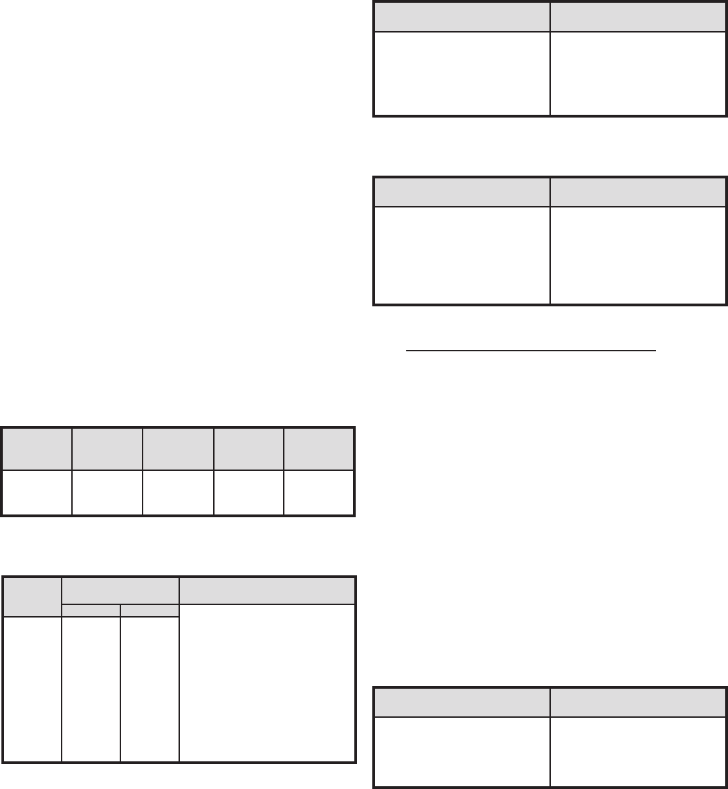
Rapid Load Calculator for Large Coolers and Freezers
The Rapid Load Calculator on page 43 may be used for quick
approximations of the heat load in large boxes and for a
reasonable comparison of heat loads gured on Bulletins
Above32-05 or Below32-05. The Calculator graph on page 43 is
based on the following average daily product loadings for coolers
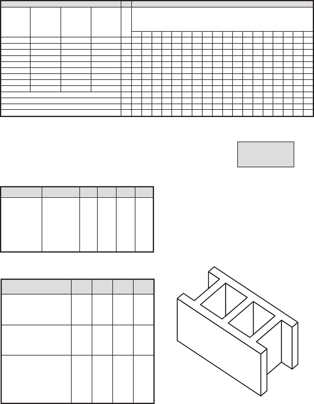
and freezers:
1. Transmission Load
Methods of determining the amount of heat ow through walls,
oor and ceiling are well established. This heat gain is directly
proportional to the Temperature Dierence (T.D.) between the
two sides of the wall. The type and thickness of insulation used
in the wall construction, the outside area of the wall and the
T.D. between the two sides of the wall are the three factors
that establish the wall load. Tables are provided to simplify
the calculations (see Table 1, page 13). Some coolers for above
freezing temperatures have been constructed with only a oor
slab (no oor insulation). The factors shown in the wall heat gain
(Table 1) are based on a concrete oor slab and the T.D. between
the local ground temperature and the storage room temperature.
Average Daily Average Daily
Volume- Product Loads (lbs.) Product Loads (lbs.)
Cu. Ft. for Coolers for Freezers
500 - 3,000 6,200 - 8,000 1,600 - 2,000
3,000 - 4,600 8,000 - 11,000 2,000 - 2,500
4,600 - 8,100 11,000 - 17,000 2,500 - 4,000
8,100 - 12,800 17,000 - 26,000 4,000 - 6,200
12,800 - 16,000 26,000 - 33,000 6,200 - 7,500
16,000 - 20,000 33,000 - 40,000 7,500 - 9,500
20,000 - 28,000 40,000 - 56,000 9,500 - 13,000
28,000 - 40,000 56,000 - 66,000 13,000 - 17,000
40,000 - 60,000 66,000 - 110,000 17,000 - 25,000
60,000 - 80,000 110,000 - 150,000 25,000 - 34,000
80,000 - up 150,000 - up 34,000 - up
5
[ (4.88) ( door height) (area/2) (minutes open) ( temp. di. ºF.)
(enthalpy incoming air – enthaply warehouse air) ] [ (1–X)]
Specic Volume of Incoming Air
Where X = % of heat transmission blocked by thermal barrier.
For freezers it becomes necessary to provide heat in the base slab
to avoid freezing of the ground water and heaving of the oor.
Minimum slab temperature should be at least 40ºF. Normally, 55ºF.
should be used for freezer applications.
2. Air Change Load
(a) Average Air Change- when the door to a refrigerated room is
opened, warm outside air will enter the room. This air must be
cooled to the refrigerated room temperature, resulting in an
appreciable source of heat gain. This load is sometimes called
the inltration load. The probable number of air changes per
day and the heat that must be removed from each cubic foot
of the inltrated air, are given in tables based on experience
(see Table 4, 5 & 6, page 14). For heavy usage, the inltration
may be doubled or more.
(b) Inltration Through a Fixed Opening- As an alternate to the
average air change method using the Psychrometric Chart
(page 37), the following formulas may be used to calculate
the inltration resulting from natural ventilation (no wind)
through external door openings.
The air change load can be substantial and every means
should be taken to reduce the amount of inltration entering
the box. Some eective means of minimizing this load are:
• Automatic closing refrigerator doors
• Vestibules or refrigerated anterooms
• Plastic strip curtains
• Air Curtains
• Inated bumpers on outside loading doors.
3. Miscellaneous Loads
Although most of the heat load in a refrigerated room
or freezer is caused by wall heat leakage, air changes and
product cooling or freezing, there are three other heat
sources that should not be overlooked prior to the selection
of the refrigeration equipment. Since the equipment has to
maintain temperature under design conditions, these loads are
generally averaged to a 24 hour period to provide for capacity
during these times.
(a) Lights- typically storage requirements are 1 to 1-1/2 watt per
square foot. Cutting or processing rooms can be double the
wattage. Each watt is multiplied by 3.42 BTU/watt to obtain a
BTUH gure. This is then multiplied by 24 to obtain a
daily gure.
(b) Motors- smaller motors are usually less ecient and tend to
generate more heat per horsepower as compared to larger
motors. For this reason Table 11, on page 18, is broken down
in to H.P. groups. Also, motors inside the refrigerated area will
reject all of their heat losses as shown in Table 11. However,
motors that are located outside but do the work inside, like
a conveyor, will reject less heat into the refrigerated space. If
powered material handling equipment is used, such as forklift
trucks, this must be included under Motor Heat Loads.
Generally only battery operated lift trucks are used in
refrigerated rooms, which represent a heat gain of 8,000 to
15,000 BTU/hr. or more over the period of operation. If motor
or loading conditions are not known, then calculate one
motor horsepower for each 16,000 cubic foot box in a storage
cooler and one HP for each 12,500 C.F. in a storage freezer
which allows for fan motors and some forklift operations.
These gures can be higher in a heavily used area, i.e. loading
dock or distribution warehouse.
(c) Occupancy- People working in the refrigerated storage area
dissipate heat at a rate depending on the room temperature
(Table 12, page 18). Multiple occupancies for short periods
should be averaged over a 24 hour period. If occupancy load
is not known, allow one person per 24 hour for each 25,000
cubic foot space.
4. Product Load
Whenever a product having a higher temperature is placed
in a refrigerator or freezer room, the product will lose its
heat until it reaches the storage temperature. This heat load
consists of three separate components: (see Table 7, page 15-
16).
(a) Specic Heat- The amount of heat that must be removed
from one pound of product to reduce the temperature of this
pound by 1ºF., is called its specic heat. It has two values: one
applies when the product is above freezing; the second is
applicable after the product has reached its freezing point.
(b) Latent Heat- The amount of heat that must be removed from
one pound of product to freeze this pound is called the latent
heat of fusion.
Most products have a freezing point in the range of 26ºF. to
31ºF. If the exact temperature is unknown, it may be
assumed to be 28ºF.
There is a denite relationship between the latent heat of
fusion and the water content of the product and its specic
and latent heats.
Estimating specic and latent heats:
Sp. Ht. above freezing = 0.20 + (0.008 X % water)
Sp. Ht. below freezing = 0.20 + (0.008 X % water)
Latent Heat = 143.3 X % water
(c) Respiration- Fresh fruits and vegetables are alive. Even in
refrigerated storage they generate heat which is called the
heat of respiration. They continually undergo a change in
which energy is released in the form of heat, which varies with
the type and temperature of the product. Tabulated values are
usually in BTU/lb./24 hours (Table 8, page 17), and are applied
to the total weight of product being stored and not just the
daily turnover.
(d) Pull down Time- When a product load is to be calculated at
other than a 24 hour pull down, a correction factor must be
multiplied to the product load.
24 hours
Pull down Time
Note: While product pull down can be calculated, no
guarantee should be made regarding nal product
temperature due to many uncontrollable factors (i.e., type of
packaging, position in the box, method of stacking, etc.)
5. Safety Factor
When all four of the main sources of heat are calculated,
a safety factor of 10% is normally added to the total
refrigeration load to allow for minor omissions and
inaccuracies (additional safety or reserve may be available
from the compressor running time and average loading).

6
6. Hourly Heat Load
The hourly heat load serves as the guide in selecting
equipment. It is found by dividing the nal BTU/24 hour load
by the desired condensing unit run time.
35ºF. rooms with no timer 16 hr.
35ºF. rooms with timer 18 hr.
Blast coolers/Freezers with
positive defrost 18 hr.
Storage Freezers 18-20 hr.
25ºF. - 34ºF. coolers with hot gas
or electric defrost 20-22 hr.
50ºF. rooms and higher with coil
temperature above 32ºF. 20-22 hr.
7. Load Calculation Forms
To simplify the calculation and tabulation of refrigeration
loads, there are two forms available:
Bulletin Above32-05 is used for all rooms above 32ºF. (0ºC.)
Bulletin Below32-05 is used for all rooms below 32ºF. (0ºC.)
All data and tables necessary to ll in the Load Calculation
Forms can be found in this manual.
A Word of Caution: The refrigeration load calculation
methods presented in this manual are intended for use
in selecting refrigeration equipment for rooms used for
holding and sometimes pulling product temperature down.
For process or unusual applications such as blast freezing or
food processing situations, please contact our Application
Engineering Department.
7
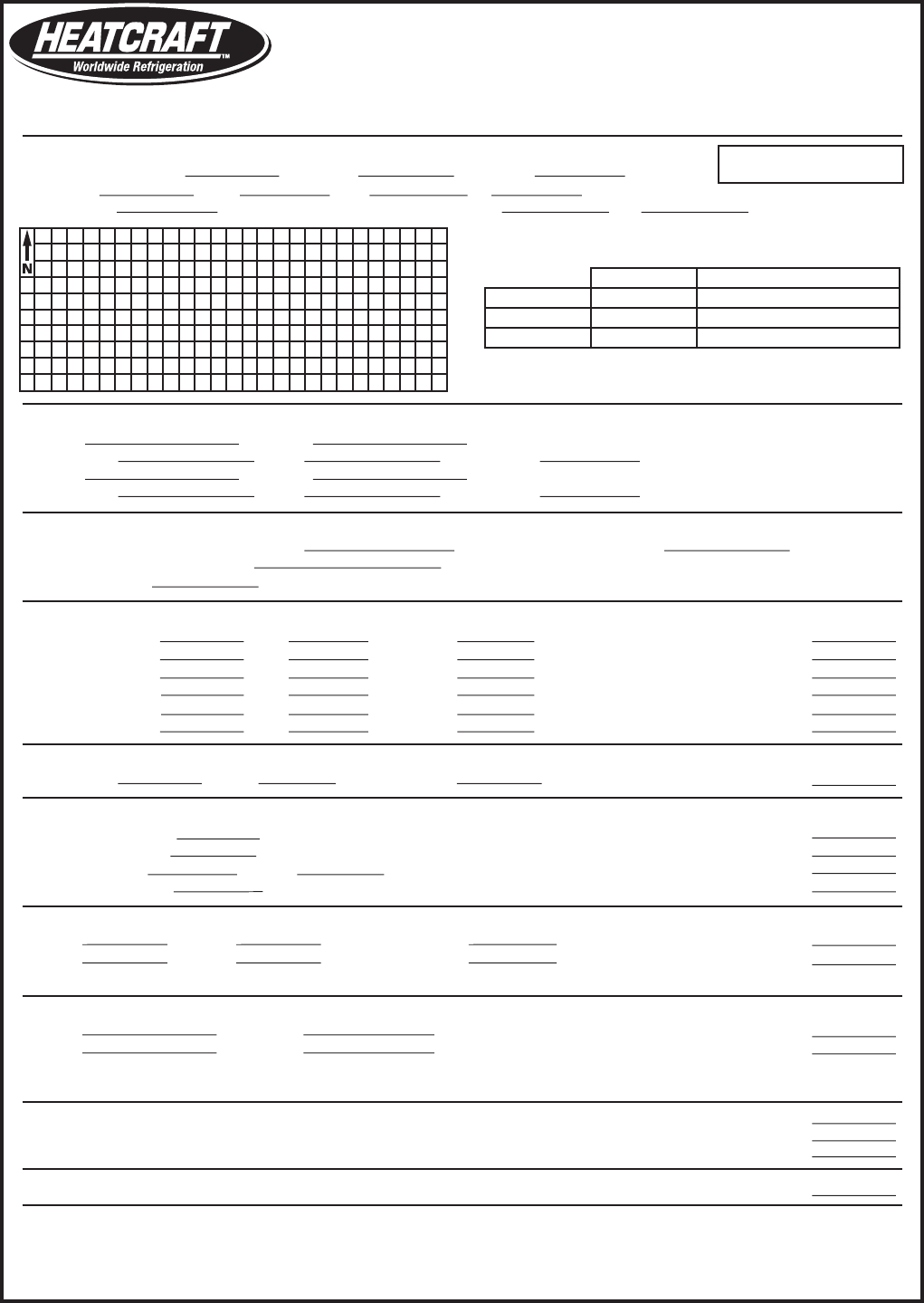
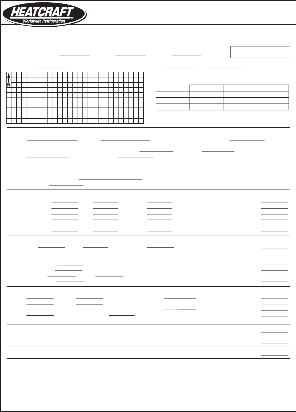
Refrigeration Load Estimate Form
(for rooms above 32ºF) Bulletin Above32-05
Basis for Estimate
Room Dimensions: Width ft. x Length ft. x Height ft.
Volume: (L) x (W) x (H) = cu. ft.
Ambient Temp ºF. (Corrected for sun load) — Room Temp ºF. = ºF. T.D.
Product Load
(a) lbs./day of to be reduced from entering
temp. of ºF. to ºF. Temp. Drop ºF.
(b) lbs./day of to be reduced from entering
temp. of ºF. to ºF. Temp. Drop ºF.
Miscellaneous
Motors (including all blower motors) HP Ground Temp. (Table 21)
Lights (assume 1 watt/sq.ft.) Watts
No. of people
2. Air Change Load
Volume: cu. ft. x Factor (Table 4) x Factor (Table 6) =
3. Additional Loads
Electrical Motors: HP x 75000 BTU/HP/24 hr. =
Electrical Lights: Watts x 82 =
People Load: People x BTU/24 hrs. (Table 12) =
Glass Door Load: Doors x 19200 BTU/Door/24 hr. =
4. Product Load: Sensible (Product Load Figured @ 24 hr. Pulldown*)
(a) lbs./day x Spec. Heat (Table 7) x ºF. Temp Drop =
(b) lbs./day x Spec. Heat (Table 7) x ºF. Temp Drop =
*For product pulldown time other than 24 hrs. figure 24 hr. load x (24/Pulldown Time)
5. Product Load: Respiration*
(a) lbs. stored x BTU/lbs./24 hrs. (Table 8) =
(b) lbs. stored x BTU/lbs./24 hrs. (Table 8) =
*For consideration of previously loaded product, a multiplier of (5) is normally applied to the daily
product load (Line #4)
Divide by No. of Operating Hrs. (16) to obtain BTUH Cooling Requirement
Equipment Selection
Condensing Unit Unit Cooler System Capacity
Qty. Model No. Qty. Model No. BTU/hr.
Total Refrigeration Load (1+2+3+4+5) BTU/24 hrs.
Add 10% Safety Factor
Total with Safety/Factor BTU/24 hrs.
1. Transmission Loads
Ceiling: (L) x (W) x Heat Load (Table 1) =
North Wall: (L) x (W) x Heat Load (Table 1) =
South Wall: (L) x (W) x Heat Load (Table 1) =
East Wall: (L) x (W) x Heat Load (Table 1) =
West Wall: (L) x (W) x Heat Load (Table 1) =
Floor: (L) x (W) x Heat Load (Table 1) =
Insulation
Inches
Ceiling
Walls
Floor
Type
2175 West Park Place Blvd. • Stone Mountain, GA 30087 • 770.465.5600 • Fax: 770.465.5990 • www.heatcraftrpd.com
Estimate for: Estimate by: Date:
Note: Tables can be found in
Engineering Manual, H-ENG-2
(H)
(H)
Example: 35ºF Convenience Store Cooler With Glass Doors
8 28 8
28 8 8 1792
85 35 50
4 Styrene
4 Styrene
6 Concrete
2000 Beer
85 35 50
200 Milk
40 35 5
0.2 60
224
0
28 8 72 16128
28 8 72 16128
28 8 72 16128
8 8 72 4608
8 8 72 4608
28 8 125 28000
1792 13 1.86 43331
0.2 15000
224 18368
0 —
10 192000
2000 0.92 50 92000
200 0.93 5 930
— — —
— — —
447229
44723
491952
30747
(W)
(H)
(W)
(H)

8
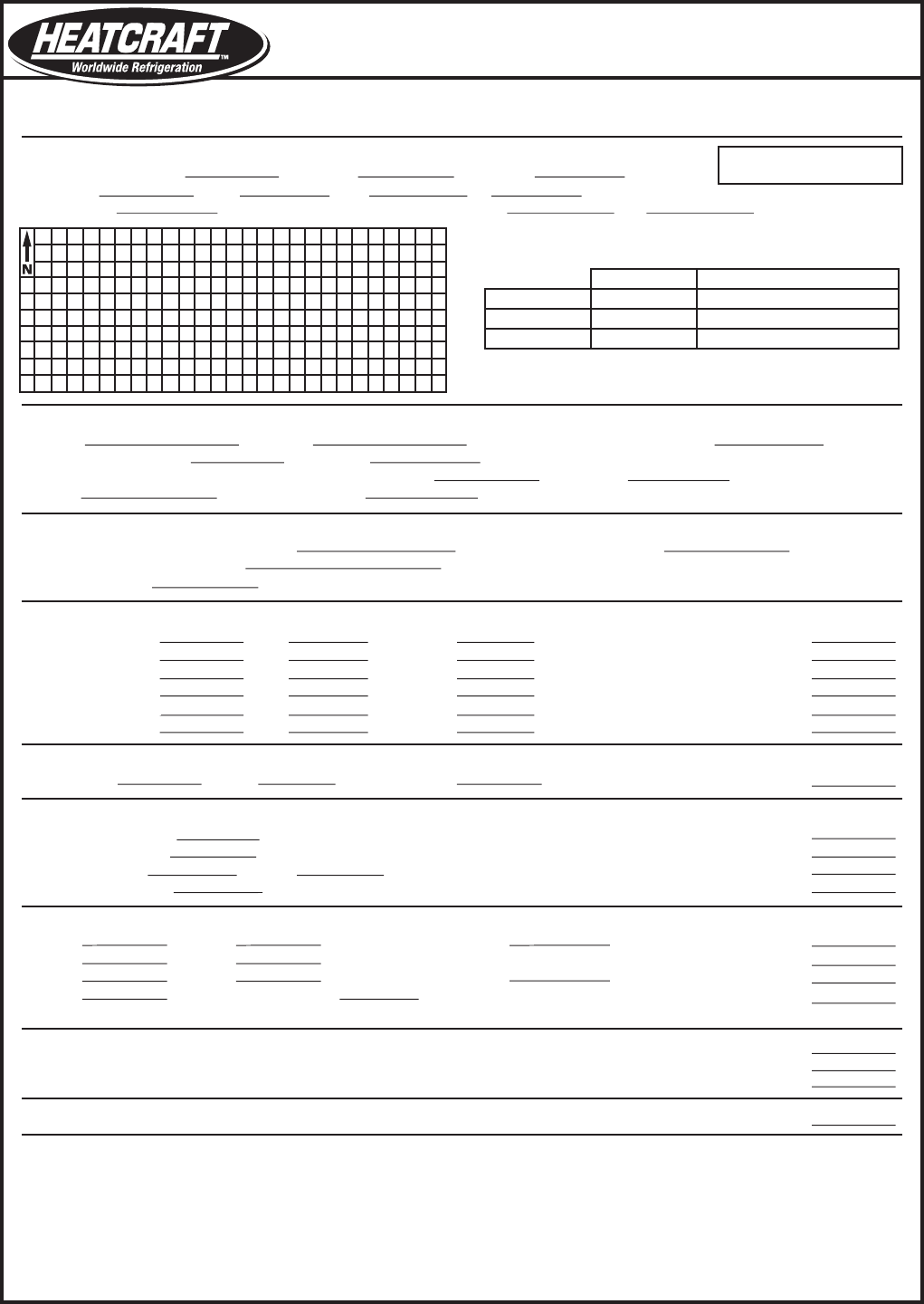
Refrigeration Load Estimate Form
(for rooms above 32ºF) Bulletin Above32-05
Basis for Estimate
Room Dimensions: Width ft. x Length ft. x Height ft.
Volume: (L) x (W) x (H) = cu. ft.
Ambient Temp ºF. (Corrected for sun load) — Room Temp ºF. = ºF. T.D.
Product Load
(a) lbs./day of to be reduced from entering
temp. of ºF. to ºF. Temp. Drop ºF.
(b) lbs./day of to be reduced from entering
temp. of ºF. to ºF. Temp. Drop ºF.
Miscellaneous
Motors (including all blower motors) HP Ground Temp. (Table 21)
Lights (assume 1 watt/sq.ft.) Watts
No. of people
2. Air Change Load
Volume: cu. ft. x Factor (Table 4) x Factor (Table 6) =
3. Additional Loads
Electrical Motors: HP x 75000 BTU/HP/24 hr. =
Electrical Lights: Watts x 82 =
People Load: People x BTU/24 hrs. (Table 12) =
Glass Door Load: Doors x 19200 BTU/Door/24 hr. =
4. Product Load: Sensible (Product Load Figured @ 24 hr. Pulldown*)
(a) lbs./day x Spec. Heat (Table 7) x ºF. Temp Drop =
(b) lbs./day x Spec. Heat (Table 7) x ºF. Temp Drop =
*For product pulldown time other than 24 hrs. figure 24 hr. load x (24/Pulldown Time)
5. Product Load: Respiration*
(a) lbs. stored x BTU/lbs./24 hrs. (Table 8) =
(b) lbs. stored x BTU/lbs./24 hrs. (Table 8) =
*For consideration of previously loaded product, a multiplier of (5) is normally applied to the daily
product load (Line #4)
Divide by No. of Operating Hrs. (16) to obtain BTUH Cooling Requirement
Equipment Selection
Condensing Unit Unit Cooler System Capacity
Qty. Model No. Qty. Model No. BTU/hr.
Total Refrigeration Load (1+2+3+4+5) BTU/24 hrs.
Add 10% Safety Factor
Total with Safety/Factor BTU/24 hrs.
1. Transmission Loads
Ceiling: (L) x (W) x Heat Load (Table 1) =
North Wall: (L) x (W) x Heat Load (Table 1) =
South Wall: (L) x (W) x Heat Load (Table 1) =
East Wall: (L) x (W) x Heat Load (Table 1) =
West Wall: (L) x (W) x Heat Load (Table 1) =
Floor: (L) x (W) x Heat Load (Table 1) =
Insulation
Inches
Ceiling
Walls
Floor
Type
2175 West Park Place Blvd. • Stone Mountain, GA 30087 • 770.465.5600 • Fax: 770.465.5990 • www.heatcraftrpd.com
Estimate for: Estimate by: Date:
Note: Tables can be found in
Engineering Manual, H-ENG-2
Example: 35ºF Beef Cooler
14 16 8
16 14 8 1792
95 35 60
4 Styrene
4 Styrene
6 Concrete
1000 Beef
50 35 15
— —
— — —
0.1 60
224
0
16 14 87 19488
16 8 87 11136
16 8 87 11136
14 8 87 9744
14 8 87 9744
16 14 125 28000
1792 13 2.49 58007
0.1 7500
224 18368
0 — —
0 —
1000 0.77 15 11550
— — — —
— — —
— — —
184673
18467
203140
12696
(W)
(W) (H)
(H)
(H)
(H)

9
Refrigeration Load Estimate Form
(for rooms above 32ºF) Bulletin Above32-05
Basis for Estimate
Room Dimensions: Width ft. x Length ft. x Height ft.
Volume: (L) x (W) x (H) = cu. ft.
Ambient Temp ºF. (Corrected for sun load) — Room Temp ºF. = ºF. T.D.
Product Load
(a) lbs./day of to be reduced from entering
temp. of ºF. to ºF. Temp. Drop ºF.
(b) lbs./day of to be reduced from entering
temp. of ºF. to ºF. Temp. Drop ºF.
Miscellaneous
Motors (including all blower motors) HP Ground Temp. (Table 21)
Lights (assume 1 watt/sq.ft.) Watts
No. of people
2. Air Change Load
Volume: cu. ft. x Factor (Table 4) x Factor (Table 6) =
3. Additional Loads
Electrical Motors: HP x 75000 BTU/HP/24 hr. =
Electrical Lights: Watts x 82 =
People Load: People x BTU/24 hrs. (Table 12) =
Glass Door Load: Doors x 19200 BTU/Door/24 hr. =
4. Product Load: Sensible (Product Load Figured @ 24 hr. Pulldown*)
(a) lbs./day x Spec. Heat (Table 7) x ºF. Temp Drop =
(b) lbs./day x Spec. Heat (Table 7) x ºF. Temp Drop =
*For product pulldown time other than 24 hrs. figure 24 hr. load x (24/Pulldown Time)
5. Product Load: Respiration*
(a) lbs. stored x BTU/lbs./24 hrs. (Table 8) =
(b) lbs. stored x BTU/lbs./24 hrs. (Table 8) =
*For consideration of previously loaded product, a multiplier of (5) is normally applied to the daily
product load (Line #4)
Divide by No. of Operating Hrs. (16) to obtain BTUH Cooling Requirement
Equipment Selection
Condensing Unit Unit Cooler System Capacity
Qty. Model No. Qty. Model No. BTU/hr.
Total Refrigeration Load (1+2+3+4+5) BTU/24 hrs.
Add 10% Safety Factor
Total with Safety/Factor BTU/24 hrs.
1. Transmission Loads
Ceiling: (L) x (W) x Heat Load (Table 1) =
North Wall: (L) x (W) x Heat Load (Table 1) =
South Wall: (L) x (W) x Heat Load (Table 1) =
East Wall: (L) x (W) x Heat Load (Table 1) =
West Wall: (L) x (W) x Heat Load (Table 1) =
Floor: (L) x (W) x Heat Load (Table 1) =
Insulation
Inches
Ceiling
Walls
Floor
Type
2175 West Park Place Blvd. • Stone Mountain, GA 30087 • 770.465.5600 • Fax: 770.465.5990 • www.heatcraftrpd.com
Estimate for: Estimate by: Date:
Note: Tables can be found in
Engineering Manual, H-ENG-2
(H)
(H)
(H)
(H)
(W)
(W)
10
Refrigeration Load Estimate Form
(for rooms below 32ºF) Bulletin Below32-05
Estimate for:
Basis for Estimate
Room Dimensions: Width ft. x Length ft. x Height ft.
Volume: (L) x (W) x (H) = cu. ft.
Ambient Temp ºF. (Corrected for sun load) — Room Temp. ºF. = ºF. T.D.
Product Load
(a) lbs./day of to be reduced from entering temp. of ºF.
to freezing point of ºF. (Table 7) = ºF. Initial temp. drop
and then reduced from freezing point to storage Temp. of ºF. = (Table 7) ºF. Final temp. drop.
(b) gallons of ice cream @ overrun
Miscellaneous
Motors (including all blower motors) HP Ground Temp. (Table 21)
Lights (assume 1 watt/sq.ft.) Watts
No. of People
2. Air Change Load
Volume: cu. ft. x Factor (Table 5) x Factor (Table 6) =
3. Additional Loads
Electrical Motors: HP x 75000 BTU/HP/24 hr. =
Electrical Lights: Watts x 82 =
People Load: People x BTU/24 hrs. (Table 12) =
Glass Door Load: Doors x 31200 BTU/Door/24 hr. =
4. Product Load: (Table 7) (Product Load Figured @ 24 hr. Pulldown*)
(a) lbs./day x Spec. Heat above freezing x ºF. Intial Temp. Drop =
lbs./day x Latent Heat Fusion =
lbs./day x Spec. Heat below freezing x ºF. Intial Temp. Drop =
(b) gallons of ice cream/day x BTU/gal (Table 19) =
*For product pulldown time other than 24 hrs. figure 24 hr. load x (24/Pulldown Time)
Divide by No. of Operating Hrs. (18) to obtain BTUH Cooling Requirement
Equipment Selection
Condensing Unit Unit Cooler System Capacity
Qty. Model No. Qty. Model No. BTU/hr.
Total Refrigeration Load (1+2+3+4+5) BTU/24 hrs.
Add 10% Safety Factor
Total with Safety/Factor BTU/24 hrs.
1. Transmission Loads
Ceiling: (L) x (W) x Heat Load (Table 1) =
North Wall: (L) x (W) x Heat Load (Table 1) =
South Wall: (L) x (W) x Heat Load (Table 1) =
East Wall: (L) x (W) x Heat Load (Table 1) =
West Wall: (L) x (W) x Heat Load (Table 1) =
Floor: (L) x (W) x Heat Load (Table 1) =
Estimate by: Date:
Insulation
Inches
Ceiling
Walls
Floor
Type
Note: Tables can be found in
Engineering Manual, H-ENG-2
2175 West Park Place Blvd. • Stone Mountain, GA 30087 • 770.465.5600 • Fax: 770.465.5990 • www.heatcraftrpd.com
(H)
(H)
(H)
Example: -20ºF Ice Cream Hardening Freezer
12 14 8
14 12 8 1344
85 -20 105
4 Foamed In place Ure
4 Foamed In place Ure
4 Foamed In place Ure
— — —
— —
— —
100 100%
0.2 60
168
0
14 12 76 12768
14 8 76 8512
14 8 76 8512
12 8 76 7296
12 8 76 7296
14 12 58 9744
1344 12 3.49 56287
0.2 15000
168 13776
0 — —
10 —
— — —
— — —
— — —
100 425 X 2.4 (10 hr. Pull down)* 102000
241191
24119
265310
14739
(W)
(W)
(H)

11
Refrigeration Load Estimate Form
(for rooms below 32ºF) Bulletin Below32-05
Estimate for:
Basis for Estimate
Room Dimensions: Width ft. x Length ft. x Height ft.
Volume: (L) x (W) x (H) = cu. ft.
Ambient Temp ºF. (Corrected for sun load) — Room Temp. ºF. = ºF. T.D.
Product Load
(a) lbs./day of to be reduced from entering temp. of ºF.
to freezing point of ºF. (Table 7) = ºF. Initial temp. drop
and then reduced from freezing point to storage Temp. of ºF. = (Table 7) ºF. Final temp. drop.
(b) gallons of ice cream @ overrun
Miscellaneous
Motors (including all blower motors) HP Ground Temp. (Table 21)
Lights (assume 1 watt/sq.ft.) Watts
No. of People
2. Air Change Load
Volume: cu. ft. x Factor (Table 5) x Factor (Table 6) =
3. Additional Loads
Electrical Motors: HP x 75000 BTU/HP/24 hr. =
Electrical Lights: Watts x 82 =
People Load: People x BTU/24 hrs. (Table 12) =
Glass Door Load: Doors x 31200 BTU/Door/24 hr. =
4. Product Load: (Table 7) (Product Load Figured @ 24 hr. Pulldown*)
(a) lbs./day x Spec. Heat above freezing x ºF. Intial Temp. Drop =
lbs./day x Latent Heat Fusion =
lbs./day x Spec. Heat below freezing x ºF. Intial Temp. Drop =
(b) gallons of ice cream/day x BTU/gal (Table 19) =
*For product pulldown time other than 24 hrs. figure 24 hr. load x (24/Pulldown Time)
Divide by No. of Operating Hrs. (18) to obtain BTUH Cooling Requirement
Equipment Selection
Condensing Unit Unit Cooler System Capacity
Qty. Model No. Qty. Model No. BTU/hr.
Total Refrigeration Load (1+2+3+4+5) BTU/24 hrs.
Add 10% Safety Factor
Total with Safety/Factor BTU/24 hrs.
1. Transmission Loads
Ceiling: (L) x (W) x Heat Load (Table 1) =
North Wall: (L) x (W) x Heat Load (Table 1) =
South Wall: (L) x (W) x Heat Load (Table 1) =
East Wall: (L) x (W) x Heat Load (Table 1) =
West Wall: (L) x (W) x Heat Load (Table 1) =
Floor: (L) x (W) x Heat Load (Table 1) =
Estimate by: Date:
Insulation
Inches
Ceiling
Walls
Floor
Type
Note: Tables can be found in
Engineering Manual, H-ENG-2
2175 West Park Place Blvd. • Stone Mountain, GA 30087 • 770.465.5600 • Fax: 770.465.5990 • www.heatcraftrpd.com
(H)
(H)
(H)
(H)
Example: -10ºF Beef Freezer
20 24 12
24 20 12 5760
90 -10 100
4 Foamed In place Ure
4 Foamed In place Ure
4 Foamed In place Ure
3000 Beef 35
28 7
-10 38
— —
0.5 60
480
0
24 20 72 34560
24 12 72 20736
24 12 72 20736
20 12 72 17280
20 12 72 17280
24 20 50 24000
5760 5.2 3.56 106629
0.5 37500
480 39360
0 — —
0 —
3000 0.77 7 16170
3000 100 300000
3000 0.4 38 45600
— X 2.4 (10 hr. Pull down)* —
679851
67985
747836
41546
(W)
(W)
12
Refrigeration Load Estimate Form
(for rooms below 32ºF) Bulletin Below32-05
Estimate for:
Basis for Estimate
Room Dimensions: Width ft. x Length ft. x Height ft.
Volume: (L) x (W) x (H) = cu. ft.
Ambient Temp ºF. (Corrected for sun load) — Room Temp. ºF. = ºF. T.D.
Product Load
(a) lbs./day of to be reduced from entering temp. of ºF.
to freezing point of ºF. (Table 7) = ºF. Initial temp. drop
and then reduced from freezing point to storage Temp. of ºF. = (Table 7) ºF. Final temp. drop.
(b) gallons of ice cream @ overrun
Miscellaneous
Motors (including all blower motors) HP Ground Temp. (Table 21)
Lights (assume 1 watt/sq.ft.) Watts
No. of People
2. Air Change Load
Volume: cu. ft. x Factor (Table 5) x Factor (Table 6) =
3. Additional Loads
Electrical Motors: HP x 75000 BTU/HP/24 hr. =
Electrical Lights: Watts x 82 =
People Load: People x BTU/24 hrs. (Table 12) =
Glass Door Load: Doors x 31200 BTU/Door/24 hr. =
4. Product Load: (Table 7) (Product Load Figured @ 24 hr. Pulldown*)
(a) lbs./day x Spec. Heat above freezing x ºF. Intial Temp. Drop =
lbs./day x Latent Heat Fusion =
lbs./day x Spec. Heat below freezing x ºF. Intial Temp. Drop =
(b) gallons of ice cream/day x BTU/gal (Table 19) =
*For product pulldown time other than 24 hrs. figure 24 hr. load x (24/Pulldown Time)
Divide by No. of Operating Hrs. (18) to obtain BTUH Cooling Requirement
Equipment Selection
Condensing Unit Unit Cooler System Capacity
Qty. Model No. Qty. Model No. BTU/hr.
Total Refrigeration Load (1+2+3+4+5) BTU/24 hrs.
Add 10% Safety Factor
Total with Safety/Factor BTU/24 hrs.
1. Transmission Loads
Ceiling: (L) x (W) x Heat Load (Table 1) =
North Wall: (L) x (W) x Heat Load (Table 1) =
South Wall: (L) x (W) x Heat Load (Table 1) =
East Wall: (L) x (W) x Heat Load (Table 1) =
West Wall: (L) x (W) x Heat Load (Table 1) =
Floor: (L) x (W) x Heat Load (Table 1) =
Estimate by: Date:
Insulation
Inches
Ceiling
Walls
Floor
Type
Note: Tables can be found in
Engineering Manual, H-ENG-2
2175 West Park Place Blvd. • Stone Mountain, GA 30087 • 770.465.5600 • Fax: 770.465.5990 • www.heatcraftrpd.com
(W)
(W)
(H)
(H)
(H)
(H)
13
Insulation Insul. K Factor 6” 8” 10” 12”
Air 4.65 6.94 6.65 6.50 6.40
Vermiculite .47 2.73 2.67 2.64 2.62
Sawdust .45 2.70 2.65 2.62 2.60
Cork .38 2.62 2.57 2.55 2.53
Rock Wool .30 2.52 2.49 2.47 2.45
Mac. Paper .28 2.50 2.46 2.45 2.43
Styrofoam .24 2.45 2.42 2.40 2.40
Polyurethane .16 2.36 2.33 2.33 2.32
Type of East South West Flat
Surface Wall Wall Wall Roof
Dark Colored Surfaces,
Such as:
Slate Roong 8 5 8 20
Tar Roong
Black Paints
Light Colored Surface,
Such as:
White Stone 4 2 4 9
Light Colored Cement
White Paint
Medium Colored Surface,
Such as:
Unpainted Wood
Brick 6 4 6 15
Red Tile
Dark Cement
Red, Gray or Green Paint
1 4 5.10 204 230 255 281 306 332 357 383 408 434 459 485 510 536 561 587 612
2 8 3.40 136 153 170 187 204 221 238 255 272 289 306 323 340 357 374 391 408
4 3 2 12.6 1.80 72 81 90 99 108 117 126 135 144 153 162 171 180 189 198 207 216
5 4 2 16.4 1.44 58 65 72 79 87 94 101 108 115 122 130 137 144 151 159 166 173
6 5 3 19.6 1.20 48 54 60 66 72 78 84 90 96 102 108 114 120 126 132 138 144
8 6 4 3 25 0.90 36 41 45 50 54 59 63 68 72 77 81 86 90 95 99 104 108
10 8 4 33 0.72 29 32 36 40 43 47 50 54 58 61 65 68 72 76 79 83 86
10 6 38.7 0.60 24 27 30 33 36 39 42 45 48 51 54 57 60 63 66 69 72
6 50 0.48 19 22 24 26 29 31 34 36 38 41 43 46 48 51 53 55 58
Single window glass . 9 27 1080 1215 1350 1490 1620 1760 1890 2030 2160 2290 2440 2560 2700 2840 2970 3100 3240
Double Window Glass 2.2 11 440 495 550 610 660 715 770 825 880 936 990 1050 1100 1160 1210 1270 1320
Triple Window Glass 3.4 7 280 315 350 390 420 454 490 525 560 595 630 665 700 740 770 810 840
6” Concrete Floor 4.8 5 200 225 250 275 300 325 350 375 400 425 450 475 500 525 550 575 600
Insulation (Inches) Heat Load (BTU Per 24 Hours Per One Square Foot of Outside Surface)
Cork Glass Urethane
or Fiber or Urethane (Foamed Temperature Reduction in ºF.
Mineral Poly- (Sprayed) in R (Outside Air Temperature Minus Room Temperature)
Wool Styrene Place)
k = .30 k = .26 k = .16 k = .12 1 40 45 50 55 60 65 70 75 80 85 90 95 100 105 110 115 120
Appendix - Tables
Note: Above insulation “K” Factors [Thermal Conductivity, BTU
per (hour) (square foot) (ºF. per inch of thickness)] and heat
gain factors for Cork and Window Glasses are extracted and
Insulation Values
“K” Factor - Insulating Value of any material is rated by its thermal conductivity
“U” Factor - Overall coecient of heat transfer, BTU per hour/per square foot/per degree F.
“R” Factor - Thermal resistances
“X” = Inches of Insulation
K = UX = X/R
U = K/X = 1/R
R = 1/U = X/K
Table 2
Eective K Factor in Block Thickness of Insulation
Note: If blocks have 3 holes, add .75 to all of the values shown. The
above data is being shown for reference purpose only - this is a very
inecient method of construction/insulation due to:
1. Concrete webs are dominant factor in calculating insulating eect.
2. Filling techniques may leave blocks improperly lled.
3. No vapor seal present - moisture inltration decreases insulation
eect.
4. If used for freezers, moisture will freeze inside block and break
out the surface of the block.
5. Blocks are highly subject to setting cracks- more inltration.
Table 3
Allowance for Sun Eect
(Fahrenheit degrees to be added to the normal temperature dierence for heat leakage
calculations to compensate for sun eect- not to be used for air conditioning design.)
reprinted by permission from ASHRAE 1972 HANDBOOK OF
FUNDAMENTALS.
Table 1
Wall Heat Loads
14
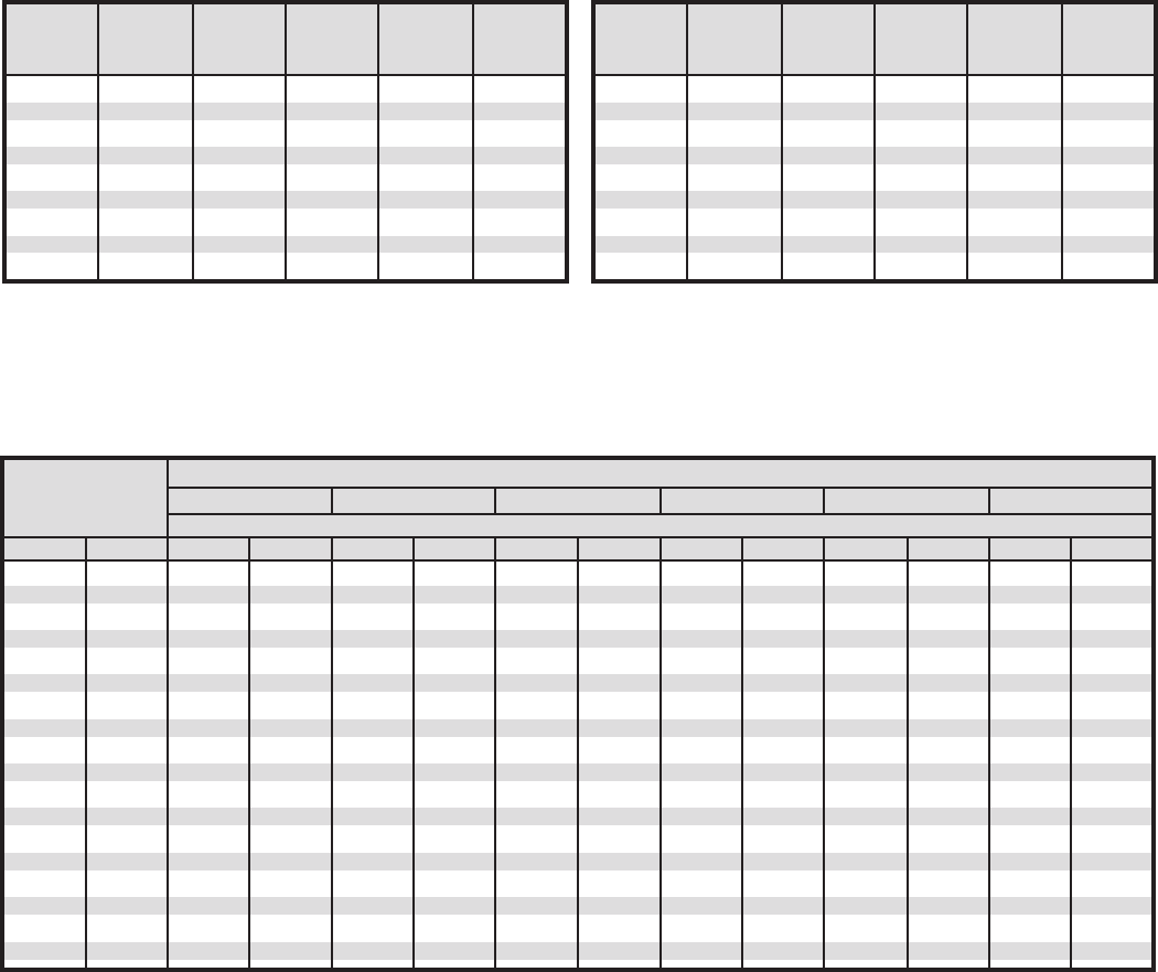
Table 4
Average air changes per 24 hours for storage rooms
above 32ºF. (0ºC.) due to door openings and inltration.
Air Air Air
Volume Changes Volume Changes Volume Changes
Cu. Ft. Per 24hrs. Cu. Ft. Per 24hrs. Cu. Ft. Per 24hrs.
200 44.0 2,000 12.0 25,000 3.0
250 38.0 3,000 9.5 30,000 2.7
300 34.5 4,000 8.2 40,000 2.3
400 29.5 5,000 7.2 50,000 2.0
500 26.0 6,000 6.5 75,000 1.6
600 23.0 8,000 5.5 100,000 1.4
800 20.0 10,000 4.9 150,000 1.2
1,000 17.5 15,000 3.9 200,000 1.1
1,500 14.0 20,000 3.5 300,000 1.0
Air Air Air
Volume Changes Volume Changes Volume Changes
Cu. Ft. Per 24hrs. Cu. Ft. Per 24hrs. Cu. Ft. Per 24hrs.
200 33.5 2,000 9.3 25,000 2.3
250 29.0 3,000 7.4 30,000 2.1
300 26.2 4,000 6.3 40,000 1.8
400 22.5 5,000 5.6 50,000 1.6
500 20.0 6,000 5.0 75,000 1.3
600 18.0 8,000 4.3 100,000 1.1
800 15.3 10,000 3.8 150,000 1.0
1,000 13.5 15,000 3.0 200,000 0.9
1,500 11.0 20,000 2.6 300,000 0.85
Table 5
Average air changes per 24 hours for storage rooms
below 32ºF. (0ºC.) due to door openings and inltration.
ºF. ºC. 70 80 70 80 50 60 50 60 50 60 50 60
55 12.8 – – – – 1.12 1.34 1.41 1.66 1.72 2.01 2.06 2.44
50 10.0 – – – – 1.32 1.54 1.62 1.87 1.93 2.22 2.28 2.65
45 7.2 – – – – 1.50 1.73 1.80 2.06 2.12 2.42 2.47 2.85
40 4.4 – – – – 1.69 1.92 2.00 2.26 2.31 2.62 2.67 3.65
35 1.7 – – 0.36 0.41 1.86 2.09 2.17 2.43 2.49 2.79 2.85 3.24
30 -1.1 0.24 0.29 0.58 0.66 2.00 2.24 2.26 2.53 2.64 2.94 2.95 3.35
25 -3.9 0.41 0.45 0.75 0.83 2.09 2.42 2.44 2.71 2.79 3.16 3.14 3.54
20 -6.7 0.56 0.61 0.91 0.99 2.27 2.61 2.62 2.90 2.97 3.35 3.33 3.73
15 -9.4 0.71 0.75 1.06 1.14 2.45 2.74 2.80 3.07 3.16 3.54 3.51 3.92
10 -12.2 0.85 0.89 1.19 1.27 2.57 2.87 2.93 3.20 3.29 3.66 3.64 4.04
5 -15.0 0.98 1.03 1.34 1.42 2.76 3.07 3.12 3.40 3.48 3.87 3.84 4.27
0 -17.8 1.12 1.17 1.48 1.56 2.92 3.23 3.28 3.56 3.64 4.03 4.01 4.43
-5 -20.6 1.23 1.28 1.59 1.67 3.04 3.36 3.41 3.69 3.78 4.18 4.15 4.57
-10 -23.3 1.35 1.41 1.73 1.81 3.19 3.49 3.56 3.85 3.93 4.33 4.31 4.74
-15 -26.1 1.50 1.53 1.85 1.92 3.29 3.60 3.67 3.96 4.05 4.46 4.42 4.86
-20 -28.9 1.63 1.68 2.01 2.00 3.49 3.72 3.88 4.18 4.27 4.69 4.66 5.10
-25 -31.7 1.77 1.80 2.12 2.21 3.61 3.84 4.00 4.30 4.39 4.80 4.78 5.21
-30 -34.4 1.90 1.95 2.29 2.38 3.86 4.05 4.21 4.51 4.56 5.00 4.90 5.44
Storage Temperature of Outside Air
Room 40ºF. (4.4ºC.) 50ºF. (10ºC.) 85ºF. (29.4ºC.) 90ºF. (32.2ºC.) 95ºF. (35ºC.) 100ºF. (37.8ºC.)
Temp. Relative Humidity of Outside Air, %
Table 6
Heat removed in cooling air storage room conditions
(BTU per Cu. Ft.)
Table 3, 4 & 5 extracted and reprinted by permission from ASHRAE 1972 Handbook of Fundamentals.
Table 6 extracted and reprinted by permission from ASHRAE 1967 Handbook of Fundamentals.
Note: For heavy usage multiply the above values by 2.0
For long storage multiply the above values by 0.6

15
Specic Specic Latent Product
Storage Conditions Highest Heat Heat Heat Loading
Storage Relative Approximate Freezing Above Below of Density
Commodity Temp. Humidity Storage Point Freezing Freezing Fusion Approx.
(Alphabetical Listing) ºF. % Life* ºF. BTU/lb./F BTU/lb./F BTU/lb. lb./Cu. Ft.
Table 7
Storage requirements and properties of perishable products
Apples 30 - 40 90 3 -8 months 29.3 0.87 0.45 121 28
Apricots 31 - 32 90 1 - 2 weeks 30.1 0.88 0.46 122 30
Artichokes (Globe) 31 - 32 95 2 weeks 29.9 0.87 0.45 120 —
Asparagus 32 - 36 95 2 -3 weeks 30.9 0.94 0.48 134 25
Avocados 45 - 55 85 - 90 2 -4 weeks 31.5 0.72 0.40 94 19
Bananas 55 - 65 85 - 90 — 30.6 0.80 0.42 108 —
Beans (Green or Snap) 40 - 45 90 - 95 7 - 10 days 30.7 0.91 0.47 128 14
Lima 32 - 40 90 1 week 31.0 0.73 0.40 94 —
Beer, Keg 35 - 40 — 3 - 8 weeks 28.0 0.92 — 129 —
Bottles, Cans 35 - 40 65 or below 3 - 6 months 28.0 0.92 — 129 —
Beets, Topped 32 95 - 100 4 - 6 months 30.1 0.90 0.46 126 23
Blackberries 31 - 32 95 3 days 30.5 0.88 0.46 122 19
Blueberries 31 - 32 90 - 95 2 weeks 29.7 0.86 0.45 118 19
Bread, Baked — — 1 - 3 months 16 to 20 0.70 0.34 46 - 53 —
Dough 35 - 40 85 - 90 3 - 72 hours — 0.75 — — —
Broccoli, Sprouting 32 95 10 - 14 days 29.0 0.92 0.47 130 13
Brussels Sprouts 32 95 3 - 5 weeks 30.5 0.88 0.46 122 —
Cabbage 32 95 - 100 3 - 4 months 30.4 0.94 0.47 132 17
Carrots, Topped, Mature 32 98 - 100 5 - 9 months 29.5 0.90 0.46 126 22
Cauliower 32 95 2 - 4 weeks 29.0 0.93 0.47 132 16
Celery 32 95 1 - 2 months 31.1 0.95 0.48 135 30
Cherries, Sour 31 - 32 90 - 95 3 - 7 days 29.0 0.87 — 120 18
Sweet 30 - 31 90 - 95 2 - 3 weeks 28.8 0.84 — — —
Chocolate (Coating) 50 - 65 40 - 50 2 - 3 months 95 - 85 0.55 0.30 40 —
Cocoa 32 - 40 50 - 70 1 year, plus — — — — —
Coconut 32 - 45 80 - 85 1 - 2 months 30.4 0.58 0.34 67 —
Coee (Green) 35 - 37 80 - 85 2 - 4 months — 0.30 0.24 147 - 21 —
Collards 32 95 10 - 14 days 30.6 0.90 — — —
Corn, Sweet (Fresh) 32 95 4 - 8 days 30.9 0.79 0.42 106 16
Cranberries 36 - 40 90 - 95 2 - 4 months 30.4 0.90 0.46 124 22
Cucumbers 50 - 55 90 - 95 10 - 14 days 31.1 0.97 0.49 137 20
Currants 31 - 32 90 - 95 10 - 14 days 30.2 0.88 0.45 120 —
Daily Products
Cheddar Cheese 40 65 - 70 6 months 8.0 0.50 0.31 53 40
Processed Cheese 40 65 - 70 12 months 19.0 0.50 0.31 56 40
Butter 40 75 - 85 1 months -4 to 31 0.50 0.25 23 —
Cream 35 - 40 — 2 - 3 weeks 31.0 0.66 - 0.80 0.36 - 0.42 79 - 107 —
Ice Cream -20 to -15 — 3 - 12 months 21.0 0.66 - 0.70 0.37 - 0.39 86 25
Milk, Fluid Whole
Pasteurized, Grade A 32 - 34 — 2 - 4 months 31.0 0.93 0.46 125 —
Condensed Sweet 40 — 15 months 5.0 0.42 0.28 40 —
Evaporated 40 — 24 months 29.5 0.79 0.42 106 —
Dates (Dried) 0 or 32 75 or less 6 - 12 months 3.7 0.36 0.26 29 24
Dewberries 31 - 32 90 - 95 3 days 27.0 0.88 — — —
Dried Fruits 32 50 - 60 9 - 12 months — 0.31 - 0.41 0.26 20 - 37 45
Eggplant 45 - 50 90 - 95 7 - 10 days 30.6 0.94 0.48 132 —
Egg, Shell 29 - 31 80 - 85 5 - 6 months 28.0 0.73 0.40 96 19
Shell, Farm Cooler 50 - 55 70 - 75 2 - 3 weeks 28.0 0.73 0.40 96 19
Frozen, Whole 0 or below — 1 year, plus 28.0 0.73 0.42 106 41
Endive (Escarole) 32 95 2 - 3 weeks 31.9 0.94 0.48 132 —
Figs, Dried 32 - 40 50 - 60 9 - 12 months — 0.39 0.27 34 45
Fresh 31 - 32 85 - 90 7 - 10 says 27.6 0.82 0.43 112 21
Fish, Fresh 30 - 35 90 - 95 5 - 15 days 28.0 0.70 - 0.86 0.38 - 0.45 89 - 112 —
Haddock, Cod 30 - 35 90 - 95 15 days 28 0.82 0.43 112 35
Salmon 30 - 35 90 - 95 15 days 28 0.71 0.39 92 33
Smoked 40 - 50 50 - 60 6 - 8 months — 0.70 0.39 92 —
Shellsh, Fresh 30 - 33 86 - 95 3 - 7 days 28.0 0.83 - 0.90 0.44 - 0.46 113 - 125 —
Tuna 30 - 35 90 - 95 15 days 28.0 0.76 0.41 100 35
Furs and Fabric 34 - 40 45 - 55 several years — — — — —
Garlic, Dry 32 65 - 70 6 - 7 months 30.5 0.69 0.40 89 —
Gooseberries 31 - 32 90 - 95 2 - 4 weeks 30.0 0.90 0.46 126 19
Grapefruit 50 - 60 85 - 90 4 - 6 weeks 30.0 0.91 0.46 126 30
Grapes, American Type 31 - 32 85 - 90 2 - 8 weeks 29.7 0.86 0.44 116 29
European Type 30 - 31 90 - 95 3 - 6 months 28.1 0.86 0.44 116 29
Greens, Leafy 32 95 10 - 14 days 30.0 0.91 0.48 136 32
Guavas 45 - 50 90 2 - 3 weeks — 0.86 — — —
Honey 38 - 50 50 - 60 1 year, plus — 0.35 0.26 26 —
Horseradish 30 - 32 95 - 100 10 - 12 months 28.7 0.78 0.42 104 —
Kale 32 95 3 - 4 months 31.1 0.89 0.46 124 —
Kohlrabi 32 95 2 - 4 weeks 30.2 0.92 0.47 128 —
Leeks, Green 32 95 1 - 3 months 30.7 0.88 0.46 126 —
Lemons 32 or 50 - 58 85 - 90 1 - 6 months 29.4 0.91 0.46 127 33
Lettuce Head 32 - 34 95 - 100 2 - 3 weeks 31.7 0.96 0.48 136 25
Limes 48 - 50 85 - 90 6 - 8 weeks 29.1 0.89 0.46 122 32
* Not based on maintaining nutritional value. Reprinted by permission from 1974 ASHRAE Applications Handbook.

16
Specic Specic Latent Product
Storage Conditions Highest Heat Heat Heat Loading
Storage Relative Approximate Freezing Above Below of Density
Commodity Temp. Humidity Storage Point Freezing Freezing Fusion Approx.
(Alphabetical Listing) ºF. % Life* ºF. BTU/lb./ºF BTU/lb./ºF BTU/lb. lb/Cu. Ft.
Table 7 Continued
Maple Sugar 75 - 80 60 - 65 1 year, plus — 0.24 0.21 7 —
Mangoes 55 85 - 90 2 - 3 weeks 30.3 0.85 0.44 117 —
Meat
Bacon, Cured (Farm Style) 60 - 65 85 4 - 6 months — 0.30 - 0.43 0.24 - 0.29 18 - 41 57
Game, Fresh 32 80 - 85 1 - 6 weeks 28 - 29 0.80 0.42 115 —
Beef, Fresh 32 - 34 88 - 92 1 - 6 weeks 28 - 29 0.70 - 0.84 0.38 - 0.43 89 - 110 —
Hams and Shoulders, Fresh 32 - 34 85 - 90 7 - 12 days 28 - 29 0.58 - 0.63 0.34 - 0.36 67 - 77 37
Cured 60 - 65 50 - 60 0 - 3 years — 0.52 - 0.56 0.32 - 0.33 57 - 64 —
Lamb Fresh 32 - 34 85 - 90 5 - 12 days 28 - 29 0.68 - 0.76 0.38 - 0.51 86 - 100 —
Livers, Frozen -10 - 0 90 - 95 3 - 4 months — — 0.41 100 —
Pork, Fresh 32 - 34 85 - 90 3 - 7 days 28 - 29 0.46 - 0.55 0.30 - 0.33 46 - 63 —
Smoked Sausage 40 - 45 85 - 90 6 months — 0.68 0.38 86 —
Fresh 32 85 - 90 1 - 2 weeks 26.0 0.89 0.56 93 —
Veal, Fresh 32 - 34 90 - 95 5 - 10 days 28 - 29 0.71 - 0.76 0.39 - 0.41 92 - 100 —
Melons, Cantaloupe 36 - 40 90 - 95 5 - 15 days 29.9 0.93 0.48 132 25
Honeydew and Honey Ball 45 - 50 90 - 95 3 - 4 weeks 30.3 0.94 0.48 132 24
Watermelons 40 - 50 80 - 90 2 - 3 weeks 31.3 0.97 0.48 132 27
Mushrooms 32 90 3 - 4 days 30.4 0.93 0.47 130 —
Milk 34 - 40 — 7 days 31 0.93 0.49 124 64
Nectarines 31 - 32 90 2 - 4 weeks 30.4 0.90 0.49 119 —
Nuts (dried) 32 - 50 65 - 75 8 - 12 months — 0.22 - 0.25 0.21 - 0.22 4 - 8 25
Okra 45 - 50 90 - 95 7 - 10 days 28.7 0.92 0.46 128 —
Oleomargarine 35 60 - 70 1 year, plus — 0.38 0.25 22 —
Olives, Fresh 45 - 50 85 - 90 4 - 6 weeks 29.4 0.80 0.42 108 —
Onions (Dry) and Onion Sets 32 65 - 70 1 - 8 months 30.6 0.90 0.46 124 —
Green 32 95 3 - 4 weeks 30.4 0.91 — — 22
Oranges 32 - 48 85 - 90 3 -12 weeks 30.6 0.90 0.46 124 34
Orange Juice, Chilled 30 - 35 — 3 - 6 weeks — 0.91 0.47 128 —
Papayas 45 85 - 90 1 - 3 weeks 30.4 0.82 0.47 130 —
Parsley 32 95 1 - 2 months 30.0 0.88 0.45 122 —
Parsnip 32 98 - 100 4 - 6 months 30.4 0.84 0.44 112 36
Peaches and Nectarines 31 - 32 90 2 - 4 weeks 30.3 0.90 0.46 124 33
Pears 29 - 31 90 - 95 2 - 7 months 29.2 0.86 0.45 118 47
Peas, Green 32 95 1 - 3 weeks 30.9 0.79 0.42 106 23
Peppers, Sweet 45 - 50 90 - 95 2 - 3 weeks 30.7 0.94 0.47 132 41
Peppers, Chili (Dry) 32 - 50 60 - 70 6 months — 0.30 0.24 17 —
Persimmons 30 90 3 - 4 months 28.1 0.84 0.43 112 —
Pineapples, Ripe 45 85 - 90 2 - 4 weeks 30.0 0.88 0.45 122 25
Plums, Including Fresh Prunes 31 - 32 90 - 95 2 - 4 weeks 30.5 0.88 0.45 118 22
Pomegranates 32 90 2 - 4 weeks 26.6 0.87 0.48 112 —
Popcorn, Unopened 32 - 40 85 4 - 6 months — 0.31 0.24 19 —
Potatoes, Early Crop 50 - 55 90 0 - 2 months 30.9 0.85 0.44 116 42
Late Crop 38 - 50 90 5 - 8 months 30.9 0.82 0.43 111 —
Poultry, Fresh Chicken 32 85 - 90 1 week 27.0 0.79 0.42 106 38
Fresh Goose 32 85 - 90 1 week 27.0 0.57 0.34 67 —
Fresh Turkey 32 85 - 90 1 week 27.0 0.64 0.37 79 25
Pumpkins 50 - 55 70 - 75 2 - 3 months 30.5 0.92 0.47 130 —
Quinces 31 - 32 90 2 - 3 months 28.4 0.88 0.45 122 —
Radishes- Spring, Prepacked 32 95 3 - 4 weeks 30.7 0.95 0.48 134 —
Raisins (Dried) 40 60 - 70 9 - 12 months — 0.47 0.32 43 45
Rabbits, Fresh 32 - 34 90 - 95 1 - 5 days — 0.74 0.40 98 22
Raspberries, Black 31 - 32 90 - 95 2 - 3 days 30.0 0.84 0.44 122 —
Red 31 - 32 90 - 95 2 - 3 days 30.9 0.87 0.45 121 —
Rhubarb 32 95 2 - 4 weeks 30.3 0.96 0.48 134 —
Rutabagas 32 98 - 100 4 - 6 moths 30.1 0.91 0.47 127 —
Salsify 32 98 - 100 2 - 4 months 30.0 0.83 0.44 113 —
Spinach 32 95 10 - 14 days 31.5 0.94 0.48 132 31
Squash, Summer 32 - 50 85 - 95 5 - 14 days 31.1 0.95 0.48 135 —
Winter 50 - 55 70 - 75 4 - 6 months 30.3 0.91 0.48 127 —
Strawberries, Fresh 31 - 32 90 - 95 5 - 7 days 30.6 0.92 0.42 129 40
Sugar, Maple 75 - 80 60 - 65 1 year, plus — 0.24 0.21 7 —
Sweet Potatoes 55 - 60 85 - 90 4 - 7 months 29.7 0.75 0.40 97 25
Syrup, Maple 31 60 - 70 1 year, plus — 0.48 0.31 51 —
Tangerines 32 - 38 85 - 90 2 - 4 weeks 30.1 0.90 0.46 125 —
Tobacco, Cigarettes 35 - 46 50- 56 6 months 25.0 — — — —
Cigars 35 - 50 60 - 65 2 months 25.0 — — — —
Tomatoes, Mature Green 55 - 70 85 - 90 1 - 3 weeks 31.0 0.95 0.48 134 25
Firm Ripe 45 - 50 85 - 90 4 - 7 days 31.1 0.94 0.48 134 21
Turnips, Roots 32 95 4 - 5 months 30.1 0.93 0.47 130 —
Vegetables (Mixed) 32 - 40 90 - 95 1 - 4 weeks 30.0 0.90 0.45 130 25
Yams 60 85 - 90 3 - 6 months 28.5 0.79 0.40 105 —
Yeast, Compressed
Baker’s 31 - 32 — — — 0.77 0.41 102 —
* Not based on maintaining nutritional value.

17
F R U I T S
VEGETABLES
MISCELLANEOUS
Table 8
Heat of Respiration (Approx.)
BTU / LB. / 24 Hrs.
Storage Temperature Degree F.
Product 32ºF. 40ºF. 60ºF. ºF. Other
Apples 0.25 - 0.45 0.55 - 0.80 1.50 - 3.40
Apricots 0.55 - 0.63 0.70 - 1.00 2.33 - 3.74
Avocados — — 6.60 - 15.35
Bananas — — 2.30 - 2.75 @ 68º 4.2 – 4.6
Blackberries 1.70 - 2.52 5.91 - 5.00 7.71 - 15.97
Blueberries 0.65 - 1.10 1.00 - 1.35 3.75 - 6.50 @ 70º 5.7 - 7.5
Cherries 0.65 - 0.90 1.40 - 1.45 5.50 - 6.60
Cherries, Sour 0.63 - 1.44 1.41 - 1.45 3.00 - 5.49
Cranberries 0.30 - 0.35 0.45 - 0.50 —
Figs, Mission — 1.18 - 1.45 2.37 - 3.52
Gooseberries 0.74 - 0.96 1.33 - 1.48 2.37 - 3.52
Grapefruit 0.20 - 0.50 0.35 - 0.65 1.10 - 2.00
Grapes - American 0.30 0.60 1.75
Grapes - European 0.15 - 0.20 0.35 - 0.65 1.10 - 1.30
Lemons 0.25 - 0.45 0.30 - 0.95 1.15 - 2.50
Limes — 0.45 1.485
Melons - Cantaloupe 0.55 - 0.63 0.96 - 1.11 3.70 - 4.22
Melons - Honey Dew — 0.45 - 0.55 1.20 - 1.65
Oranges 0.22 - 0.50 0.65 - 0.80 1.85 - 2.60
Peaches 0.45 - 0.70 0.70 – 1.00 3.65 – 4.65
Pears 0.35 - 0.45 2.20 4.40 - 6.60
Plums 0.20 - 0.35 0.45 - 0.75 1.20 - 1.40
Raspberries 1.95 - 2.75 3.40 - 4.25 9.05 - 11.15
Strawberries 1.35 - 1.90 1.80 - 3.40 7.80 - 10.15
Tangerines 1.63 2.93 —
Artichokes (Globe) 2.48 - 4.93 3.48 - 6.56 8.49 - 15.90
Asparagus 2.95 - 6.60 5.85 - 11.55 11.00 - 25.75
Beans, Green or Snap — 4.60 - 5.70 16.05 - 22.05
Beans, Lima 1.15 - 1.60 2.15 - 3.05 11.00 - 13.70
Beets, Topped 1.35 2.05 3.60
Broccoli 3.75 5.50 - 8.80 16.90 - 25.00
Brussels Sprouts 1.65 - 4.15 3.30 - 5.50 6.60 - 13.75
Cabbage 0.60 0.85 2.05
Carrots, Topped 1.05 1.75 4.05
Cauliower 1.80 - 2.10 2.10 - 2.40 4.70 - 5.40
Celery 0.80 1.20 4.10
Corn, Sweet 3.60 - 5.65 5.30 - 6.60 19.20
Cucumber — — 1.65 - 3.65
Garlic 0.33 - 1.19 0.63 - 1.08 1.18 - 3.00
Horseradish 0.89 1.19 3.59
Kohlrabi 1.11 1.78 5.37
Leeks 1.04 - 1.78 2.15 - 3.19 9.08 - 12.82
Lettuce, Head 1.15 1.35 3.95
Lettuce, Leaf 2.25 3.20 7.20
Mushrooms 3.10 7.80 — @ 50º 11.0
Okra — 6.05 15.8
Olives — — 2.37 - 4.26
Onions, Dry 0.35 - 0.55 0.90 1.20
Onions, Green 1.15 - 2.45 3.00 - 7.50 7.25 - 10.70
Peas, Green 4.10 - 4.20 6.60 - 8.00 19.65 - 22.25
Peppers, Sweet 1.35 2.35 4.25
Potatoes, Immature — 1.30 1.45 - 3.40
Potatoes, Mature — 0.65 - 0.90 0.75 - 1.30
Potatoes, Sweet — 0.85 2.15 - 3.15
Radishes with Top 1.59 - 1.89 2.11 - 2.30 7.67 - 8.50
Radishes, Topped 0.59 - 0.63 0.85 - 0.89 3.04 - 3.59
Rhubarb, Topped 0.89 - 1.44 1.19 - 2.00 3.41 - 4.97
Spinach 2.10 - 2.45 3.95 - 5.60 18.45 - 19.00
Squash Yellow 1.30 - 1.41 1.55 - 2.04 8.23 - 9.97
Tomatoes, Mature Green — 0.55 3.10
Tomatoes, Ripe 0.50 0.65 2.80
Turnips 0.95 1.10 2.65
Vegetables, Mixed 2.00 4.00 —
Caviar, Tub — — 1.91
Cheese, American — — 2.34
Camembert — — 2.46
Limburger — — 2.46
Roquefort — — — @ 45º 2.0
Swiss — — 2.33
Flowers, Cut 0.24 BTU / 24 Hrs. / Sq. Ft. Floor Area
18
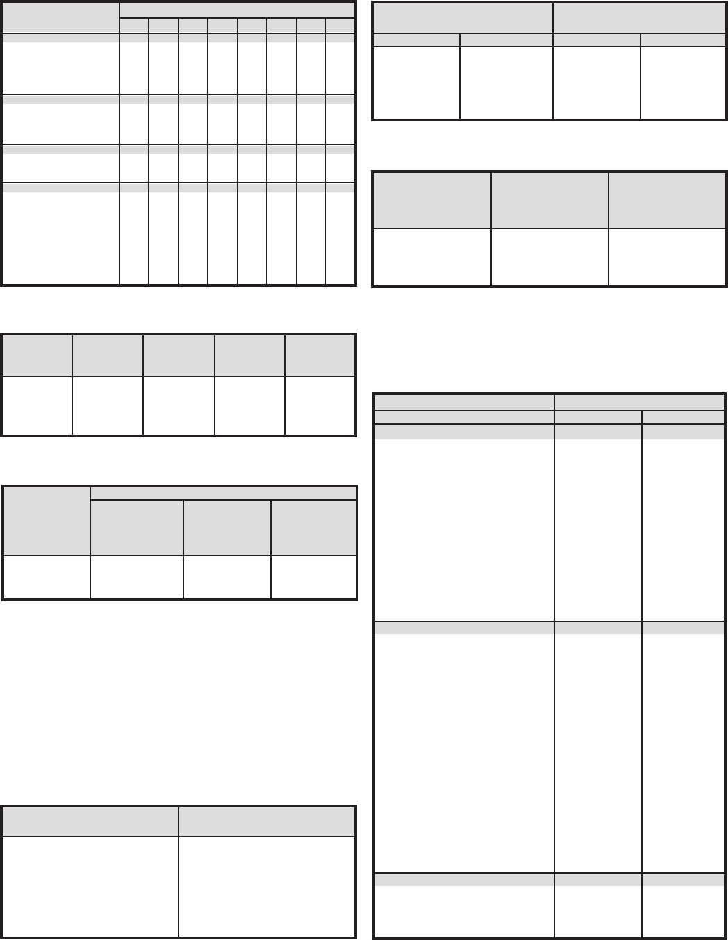
Table 9
Heat Loads of Keg and Bottled Beer (BTU / 24 HR)
Type and Size Temperature Reduction of Beer only. ºF.
of Container 60 50 40 30 20 15 10 5
Wood
One Keg — — 12000 9000 6000 4500 3000 1500
Half Keg — — 5600 4650 3100 2325 1550 775
Quarter Keg — — 3200 2400 1600 1200 800 400
Eighth Keg — — 1640 1230 820 615 410 205
Aluminum
Half Keg — — 5200 3900 2600 1950 1300 650
Quarter Keg — — 2560 1920 1280 960 640 320
Eighth Keg — — 1400 1050 700 525 350 175
Steel
Half Keg — — 4800 3600 2600 1800 1200 600
Quarter Keg — — 2400 1800 1200 900 600 300
Bottles
6 oz. 32 27 22 16 10.8 8.1 5.4 2.7
7 oz. 37 31 25 20 124 9.3 6.2 3.1
8 oz. 42 35 28 21 14.0 10.5 7.0 3.5
9 oz. 47 38 30 23 15.2 11.4 76 3.8
12 oz. 60 50 40 30 20 15 10 5.0
Cases of 24 - 12 oz.
Bottles/Cans 1920 1600 1280 960 640 480 320 160
Table 13
General standard for insulation thickness in storage rooms
ºF. ºC. Styrofoam Urethane
-50º to -25º -45º to -32º 8 6
-25º to -0º -32º to -18º 6 4
0º to 25º -18º to -4º 4 4
25º to 40º -4º to 5º 4 3 - 4
40º and up +5º and up 2 2
Storage Desirable Insulation
Temperature Thickness in Inches
Battery Heat Gain Approximate
operated per hour of total weight
load capacity truck operation of lift truck
lb. BTU / hr.* lb.
2,000 14,000 6,000
4,000 21,000 8,000
6,000 23,000 12,000
8,000 26,000 14,000
Table 14
Heat gain due to operation of battery operated lift truck
* Heat gain from lift trucks with internal combustion engines can
be approximated by multiplying the engine horsepower by 2,545
by the number of hours of operation (BTU/24 Hrs.)
Average Entering Final
Weight Specic Carcass Carcass
Carcass lbs. Heat Temp. ºF. Temp. ºF.
Cattle 550 0.77 106 35
Calves 150 0.76 104 35
Sheep 45 0.76 101 33
Hogs 180 0.54 106 35
Table 12
Heat equivalent of Occupancy
BTU per (HP) (HR)
Motor Connected
Connected Losses Load
Motor Load In Outside Outside
HP Refr Space1 Refr Space2 Refr Space3
1/8 to 1/2 4,250 2,545 1,700
1/2 to 3 3,700 2,545 1,150
3 to 20 2,950 2,545 400
Table 10
Carcass Weight
1 For use when both useful output and motor losses are dissipated
within refrigerator space: motors driving fans for forced circulation
unit coolers.
2 For use when motor losses are dissipated outside refrigerated space
and useful work of motor is expended within refrigerated space:
pump on a circulating brine or chilled water system, fan motor out-
side refrigerated space driving fan circulating air within refrigerated
space.
3 For use when motor heat losses are dissipated within refrigerated
space and useful work expended outside of refrigerated space: motor
in refrigerated space driving pump or fan located outside of space.
Cooler Heat Equivalent / Person
Temperature ºF. BTU / 24 Hrs.
50 17,280
40 20,160
30 22,800
20 25,200
10 28,800
0 31,200
-10 33,600
Table 11
Heat equivalent of electric motors
Table 15
Specic heats of various liquids and solids
Liquids
Acetic Acid 0.522 79 - 203
Alcohol-Ethyl 0.680 32 - 208
Alcohol-Methyl 0.610 59 - 68
Calcium Chloride
Brine (20% by wt.) 0.744 68
Carbon
Tetrachloride 0.201 68
Chloroform 0.234 68
Gasoline 0.500 32 - 212
Glycerine 0.575 59 - 120
Olive Oil 0.471 44
Toluene 0.404 68
Turpentine 0.420 68
Solids
Aluminum 0.214 —
Asphalt 0.220 —
Bakelite 0.350 —
Brickwork 0.200 —
Brass 0.090 —
Bronze 0.104 —
Concrete 0.156 —
Glass 0.200 —
Ice 0.465 -4
Ice 0.487 32
Iron (Cast) 0.120 —
Lead 0.031 —
Paper 0.320 —
Porcelain 0.180 —
Rubber Goods 0.480 —
Sand 0.191 —
Steel 0.120 —
Woods
Fir 0.650 —
Oak 0.570 —
Pine 0.670 —
Specic Heat
Name BTU/lb./ºF. Temp ºF.
19
Banana Ripening Room
Banana hands or cluster shipped greens in berboard cartons,
10” x 16” x 22”, holding 42 lb. net (47 lbs. gross weight) with
864 boxes (3,288) lbs, net in a carload lot. Temperature held 56 to
58ºF.
Ripening facility consists of 5 or more air tight rooms to permit a
completely weekly turn-over (1/2 carload room, measuring 30’ x
6’ x 22’H outside, holds 432 boxes packed, 24 boxes each on 18
pallets stacked 3 high by 6 long). Ripening process started with
ethylene gas and ripening schedules maintained by control of
room temperatures.
Heating is provided to bring the load up to temperature before
ripening process is initiated. 12 to 20 Kw per carload. (Electric
heater sheath temperature not over 600ºF. in dead still air).
Evaporators are selected at a T.D. of 15ºF., or less, with evaporator
temperature controlled at no less than 40ºF. Approximately 12.5
cfm at 2/3” to 3/4” static per 41 lb. box of bananas.
Pull down load for 1ºF./hr. pull down rate based on maximum heat
of respiration of 2.5 BTU/lb. and 0.8 sp. ht. for bananas and 0.4 for
berboard boxing, plus minimal wall losses etc., 80 to 85 BTU/hr./
box of bananas. Holding load approximately 44 BTU/hr./box.
Extracted from ASHRAE 1974 APPLICATION HANDBOOK.
Loading: 5.3 lbs./Cu. Ft. of box, 11.28 lbs. net per pallet
Number Evaporator Approx. Elect.
Room Boxes BTU Per CFM Air Heat
Size Prod. 10º TD Volume Input
1/2 Car 432 36000 6000 6Kw
1 Car 864 72000 12000 12Kw
2 Car 1728 144000 24000 24Kw
Table 16
Banana Rooms – Refrigeration Requirements
Floor Approx. 65% R.H.
SQ FT Room Temp.
55ºF. 50ºF.
100 93 105
200 88 99
300 85 95
400 81 90
500 78 87
600 75 85
700 72 81
800 69 78
900 67 75
1000 65 73
1200 62 69
Room Loads based on continuous
operation and includes allowance
for average number of personnel,
processing equipment, etc., with
glass panel in one wall and walls
and ceiling insulated with 3” of
styrene with box located in air
conditioned area. Evaporator
should be low outlet velocity type
to avoid drafts and should be
selected for continuous operation
and not less than 30ºF. evap. temp.
Table 17
Meat Cutting/Prep Room Load (BTU/HR/SQ FT of oor area)
Table 18
Rapid load selection for back bars
(Based on 2” glass ber or equivalent insulation and 50ºF., T.D.)
Back Bar BTU/Hour Load Based on
Length in feet 16 Hour Compressor Operation
6 Feet 1,060
8 Feet 1,416
10 Feet 1,770
12 Feet 2,120
15 Feet 2,650
20 Feet 3,540
Table 19
Refrigeration requirements for hardening ice cream
Overrun Hardening Load, BTU
Percent per Gal. Ice Cream
60 532
70 500
80 470
90 447
100 425
110 405
120 386
Percentage overrun =
100 x Wt. per gal. of mix - Wt. per gal. of ice cream
Wt. per gal. of ice cream
Ice cream assumed at 25ºF., and 30% frozen, entering
hardening room.
To retain a smooth texture in hardened ice cream, it
is necessary to freeze the remaining water content
rapidly. With forced air circulation, time to harden
will be about 10 hours with room maintained at
-20. Hardening rooms are usually sized to allow for
minimum of 3 times the daily peak production and for
a stock of all avors with the size based on 10 gallons
per sq. ft. stacked solid 6 ft. high, including space for
isles.
Reprinted by permission from
ASHRAE 1974 APPLICATION HANDBOOK
Table 20
Glass Door Loads
Box BTU per
Temperature Door
+35 1060
+30 960
0 1730
-10 1730
-20 1730
* Adjusted for 16-18 hour run time. Multiply number of doors
times door load above and add to box load.

20
Design Design Ground
Dry Bulb Wet Bulb Temp.
State City ºF. ºC. ºF. ºC. ºF. ºC.
Alabama Birmingham 95 35 78 26 70 21
Mobile 95 35 80 27 75 24
Alaska Fairbanks 82 28 64 18 40 4
Arizona Phoenix 105 41 76 24 80 27
Tucson 105 41 72 22 80 27
Yuma 110 43 78 26 80 27
Arkansas Little Rock 95 35 78 26 70 21
California Bakerseld 105 41 70 21 75 24
Fresno 105 41 74 23 80 27
Los Angeles 85 29 65 18 65 18
San Francisco 85 29 65 18 65 18
Colorado Denver 95 35 64 18 60 16
Connecticut Hartford 93 34 75 24 65 18
New Heaven 95 35 75 24 65 18
Delaware Wilmington 95 35 78 26 65 18
Dist. of Col. Washington 95 35 78 26 65 18
Florida Jacksonville 95 35 78 26 80 27
Miami 91 33 79 26 80 27
Tampa 95 35 78 26 80 27
Georgia Atlanta 95 35 76 24 72 21
Augusta 98 37 76 24 75 24
Savannah 95 35 78 26 75 24
Hawaii Honolulu 85 29 73 23 80 27
Idaho Boise 95 35 65 18 60 16
Illinois Chicago 95 35 75 24 60 16
Peoria 96 36 76 24 60 16
Indiana Fort Wayne 95 35 75 24 60 16
Indianapolis 95 35 76 24 60 16
Iowa Des Moines 95 35 78 26 60 16
Sioux City 95 35 78 26 60 16
Kansas Topeka 100 38 78 26 60 16
Wichita 100 38 75 24 60 16
Kentucky Louisville 95 35 78 26 65 18
Louisiana New Orleans 95 35 80 27 75 24
Shreveport 100 38 78 26 70 21
Maine Portland 90 32 73 23 60 16
Maryland Baltimore 95 35 78 26 65 18
Cumberland 95 35 75 24 65 18
Mass. Boston 92 33 75 24 65 18
Springeld 93 34 75 24 65 18
Michigan Detroit 95 35 75 24 60 16
Grand Rap. 95 35 75 24 60 16
Saginaw 95 35 75 24 60 16
Minnesota Minneapolis 92 33 77 25 60 16
Mississippi Vicksburg 95 35 78 26 75 24
Missouri Kansas City 100 38 76 24 60 16
St. Louis 95 35 78 26 60 16
Montana Helena 95 35 67 19 55 13
Table 21
Summer outside air and ground temperature design conditions
Design Design Ground
Dry Bulb Wet Bulb Temp.
State City ºF. ºC. ºF. ºC. ºF. ºC.
Nebraska Omaha 95 35 78 26 60 16
Nevada Reno 95 35 65 18 65 18
New Hamp. Concord 90 32 73 23 55 13
New Jersey Atlantic City 95 35 78 26 65 18
Newark 95 35 75 24 65 18
Trenton 95 35 78 26 65 18
New Mexico Santa Fe 90 32 65 18 65 18
New York Albany 93 34 75 24 60 16
Bualo 93 34 73 23 65 18
New York 95 35 75 24 65 18
N. Carolina Asheville 93 34 75 24 70 21
Charlotte 95 35 78 26 70 21
Raleigh 95 35 78 26 70 21
North Dakota Bismarck 95 35 73 23 50 10
Ohio Cincinnati 95 35 78 26 65 18
Cleveland 95 35 75 24 65 18
Columbus 95 35 76 24 60 16
Toledo 95 35 75 24 65 18
Oklahoma Okla. City 101 38 77 25 65 18
Tulsa 101 38 77 25 65 18
Oregon Portland 90 32 68 20 70 21
Pennsylvania Erie 93 34 75 24 65 18
Philadelphia 95 35 78 26 70 21
Pittsburgh 95 35 75 24 65 18
Scranton 95 35 75 24 65 18
Rhode Island Providence 93 34 75 24 65 18
S. Carolina Charleston 95 35 75 26 75 24
Greenville 95 35 76 24 75 24
South Dakota Sioux Falls 95 35 75 24 55 13
Tennessee Chattanooga 95 35 76 24 70 21
Knoxville 95 35 75 24 70 21
Memphis 95 35 78 26 70 21
Nashville 95 35 78 26 70 21
Texas Amarillo 100 38 72 22 70 21
Dallas 100 38 78 26 70 21
El Paso 100 38 69 21 70 21
Galveston 95 35 80 27 75 24
Houston 95 35 80 27 75 24
San Antonio 100 38 78 26 75 24
Utah Salt Lake City 95 35 65 18 60 16
Vermont Burlington 90 32 73 23 60 16
Virginia Norfolk 95 35 78 26 75 24
Richmond 95 35 78 26 70 21
Roanoke 95 35 76 24 70 21
Washington Seattle 85 29 65 18 75 24
Spokane 93 34 65 18 60 16
West Virginia Charleston 95 35 75 24 65 18
Wheeling 95 35 75 24 65 18
Wisconsin Green Bay 95 35 75 24 55 13
Milwaukee 95 35 75 24 55 13
Wyoming Cheyenne 95 35 65 18 55 13
Extracted by permission from Handbook of Air Conditioning, Heating and
Ventilation. Second Edition, by Strock and Koral, Industrial Press.

21
Refrigeration Equipment Selection
General
When the hourly BTU load has been determined, equipment can
now be selected based on the information obtained in the initial
job survey. Some of the factors aecting equipment selection are:
1. Equipment Balance
2. Temperature Dierence (T.D.)
3. Capacity Control/Product Safety
4. Type of Operation/Air Flow
1. Equipment Balance
The condensing unit is generally selected rst to have capacity
greater than the calculated cooling or freezing load. The
unit cooler(s) must be selected to balance the capacity of the
condensing unit.
The capacity of the condensing unit should be selected at a
suction temperature (after correction for suction line pressure
drop) which will balance with the unit cooler(s) at a desirable
T.D. between the refrigerant in the unit cooler and the air in the
refrigerated storage room. The condensing unit capacity must also
be selected at a condensing temperature corresponding to the
condensing medium (ambient air or water) temperature available
at the job location.
2. Temperature Dierence
For Storage Rooms Above 32ºF. (0ºC.)
The nature of the product determines the desirable relative
humidity for the storage room. The desirable relative humidity,
in turn, dictates the approximate design T.D. between the air in
storage room and the refrigerant in the unit cooler.
For the general purpose cooler involving meats, vegetables, and
dairy products, it is common procedure to balance the low side
to the condensing unit at a 10ºF. to 12ºF. T.D.. It has been learned
by experience that if this is done, one may expect to maintain in
a cooler 80% to 85% relative humidity, which is a good range for
general storage.
Load Calculation Example 2 (page 8) involved the cooling and
storage of beef. The table shows that the recommended T.D.
is approximately 10ºF. Since the calculated load per hour based
on 16 hr. of condensing unit operation was 12696 BTU/hr., the
condensing unit to be selected should have a greater capacity
than 12696 BTU/hr. based on a suction temperature of +23ºF.
(10ºF. T.D. plus 2ºF. allowance for suction line pressure drop).
The unit cooler to be selected should have a minimum base
capacity (BTU/º T.D.) of 12696/10º T.D. or 1270 BTU/º T.D./hr. to be
sure that the unit cooler is large enough to balance properly with
the condensing unit.
Low relative humidity requirements permit higher T.D. which in
turn will allow selection of unit coolers with small base ratings
(BTU/hr./º T.D.)
For Storage Rooms Below 32ºF. (0ºC.)
In low temperature rooms the amount of dehydration of
unwrapped products is proportional to the T.D. Since the
prevention of excess dehydration is important and since low
temperature condensing unit capacities drop o sharply as the
suction temperature reduced, it is considered good practice to use
a maximum T.D. of 10ºF.
T.D.’s can be approximated by dividing the unit cooler capacity at
a 1º T.D. into the condensing unit capacity at the desired saturated
suction temperature (S.S.T.) for example:
Condensing Unit Capacity at S.S.T. = T.D.
Evaporating Capacity at 1º T.D.
Class T.D. Approx. RH Description of Product Classes
1 7º - 9ºF. 90% Results in a minimum amount of moisture
evaporation during storage. Includes
vegetables, produce, owers,
unpackaged ice and chill rooms.
2 10º - 12ºF. 80 - 85% Includes general storage & convenience
store coolers, packaged meats and
vegetables, fruits and similar products.
Products require slightly lower relative
humidity levels than those in Class I.
3 12º - 16ºF. 65 - 80% Includes beer, wine, pharmaceuticals,
potatoes and onions, tough skin fruits
such as melons & short term packaged
products. These products require only
moderate relative humidity.
4 17º - 22ºF. 50 - 65% Includes prep and cutting rooms, beer
warehouses, candy or lm storage and
loading docks. These applications need
only low relative humidities or are
unaected by humidity.
Recommended Temperature Dierences (T.D.)
for Four Classes of Foods (Forced Air Unit Coolers)
3. Product Safety/Capacity Control
In large boxes, it is recommended that the load be divided among
multiple units. A load that requires more than a 10 HP unit should
be split to provide the customer with some refrigeration level in the
event of mechanical failure. In addition, as refrigeration is selected
for the 1% worst occurrence of the year, multiple units provide for
some capacity control. In low load situations some units can be
turned o and the box maintained adequately with a fraction of
the horsepower necessary for the summer operation. Multiple units
on staged start up also cut the demand charges assessed by the
utility company which cut your customer’s electric bill.
22
Holding freezer 40 80
Packaged Holding center 40 80
Cutting Room 20 30
Meat Chill Room 80 120
Boxed Banana Ripening 120 200
Vegetables and Fruit Storage 30 60
Blast Freezer 150 300
Work Areas 20 30
Unpackaged Meat Storage 30 60
Recommended Number
of Air Changes
Type of Application Minimum Maximum
-1,000 31.02 15.27 .0778 1.04 1.03 1.005
-500 30.47 14.97 .0763 1.02 1.02 1.002
0 29.92 14.70 .0749 1.00 1.00 1.00
500 29.38 14.43 .0735 0.98 0.98 0.995
1,000 28.86 14.28 .0719 0.96 0.96 0.998
2,000 27.82 13.67 .0697 0.93 0.93 0.985
3,000 26.81 13.27 .0671 0.90 0.90 0.98
4,000 25.84 12.70 .0647 0.86 0.875 0.975
5,000 24.89 12.23 .0623 0.83 0.85 0.969
6,000 23.98 11.78 .0600 0.80 0.82 0.960
7,000 23.09 11.34 .0578 0.77 0.79 0.955
8,000 22.22 10.92 .0556 0.74 0.76 0.946
9,000 21.38 10.50 .0535 0.71 0.73 0.939
10,000 20.58 10.11 .0515 0.69 0.71 0.93
12,000 19.03 9.35 .0477 0.64 0.66 0.91
14,000 17.57 8.63 .0439 0.59 0.61 0.88
Altitude Absolute Pressure Standard Capacity
Feet Air Multipliers
Above Density Air Direct Drive Fans
Sea At 70ºF. Dens. Refrig. Air Cooled
Level In. Hg. PSIA lbs./Cu.Ft. Ratio Evap. Cond. Unit
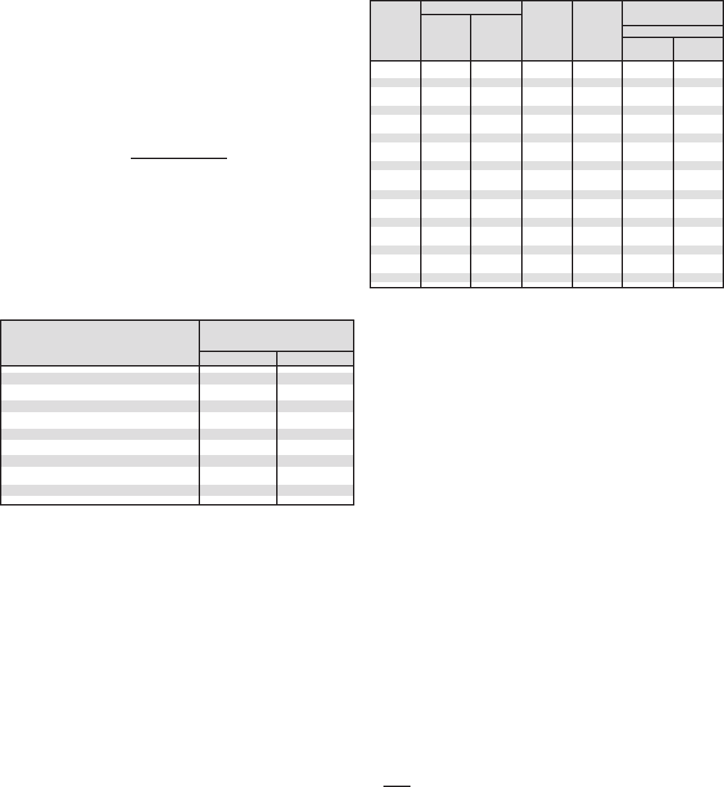
4. Type of Operation/Air Flow
Two important considerations in the selection and location of the
unit cooler are uniform air distribution and air velocities which are
compatible with the particular application.
The direction of the air and air throw should be such that there
is movement of air where there is a heat gain; this applies to the
room walls and ceiling as well as the product. The unit cooler(s)
should be arranged to direct its discharge air at any doors or
openings, if it all possible. Avoid placing the unit cooler in a
position close to a door where it may induce additional inltration
in to the room; this can cause fan icing and a condition known as
hoar-frost. Also, avoid placing a unit in the air stream of another
unit, because defrosting diculties can result.
For general storage coolers and holding freezers, there are not
criteria for air velocities within the room. The total supply of air
is such that approximately 40 to 80 air changes occur each hour.
This is an air conditioning term which is calculated as follows:
Air Changes = (total cfm*) x 60
internal room volume
* includes all unit coolers and auxiliary fans
This equation disregards the air motion which is induced by the
discharge air from the unit cooler. For simplicity, the gross volume
of the room is used unless the product and equipment occupy
more than 10% of the volume. Specic applications such as
cutting rooms and banana ripening rooms have desired limits. The
table below indicates the minimum and maximum quantities of air
for particular applications.
Derating Factors
A. Ambient
B. Altitude
C. Saturated Suction Temperature (S.S.T.)
D. 50 Cycle Power
In the selection of refrigeration equipment it should be noted
that the manufacturer’s equipment has ratings based on certain
criteria. Care should be taken to determine actual job conditions
and the proper derating factors should be applied. These factors
may vary by manufacturer but can be used here as rule of thumb
approximation.
A. Ambient
Condensing unit ambient is of concern as most equipment is
generally cataloged as 90º to 95ºF. ambient.
Decrease condensing unit capacity 6% for each 10ºF. increase
in operating ambient.
Increase condensing unit capacity 6% for each 10ºF. decrease
in operating ambient.
Recommended Air Changes/Hour
B. Altitude
Most manufacturers rate their equipment at sea level conditions.
An increase in altitude results in a decrease in air density. While
the fans on direct drive equipment will deliver a constant cubic
feet per minute of air regardless of density, the thinness of the
air will aect capacity performance. Belt drive equipment can be
speeded up to compensate for the decrease in air density.
C. Suction Temperature
Care should be taken in the selection of unit coolers, especially
freezer models. There is no set rating standard adopted by the
industry for the ratings criteria. The model number of a low
temperature unit cooler can be rated at -30º SST, -20º SST, -10º
SST, 0º SST, or even +10º SST. The capacity dierence between
the -30º SST and the +10º SST can be as much as 15% higher for
the lower rated unit cooler. Most manufacturers provide a suction
temperature correction factor for their unit coolers and this
should be noted in equipment selections.
D. 50 Cycle Power
Since we live in a “global village,” the opportunity to quote
refrigeration equipment for export markets is one not to be
ignored. Motors that are sized for 60 cycle operation run at 83%
(50/60) speed on 50 cycles operation. Compressors produce only
5/6 of their capacity. However, while fans are only running 83%
speed, there is also a decrease in static pressure through the
condenser or unit cooler coil and performance does not suer the
full 17% penalty. If it has been veried by the manufacturer that
their equipment can be run on 50 cycle power then the following
derating factors can be applied:
A. Unit coolers and air-cooled condensers (Capacity x 0.92)
B. Air-cooled condensing units (capacity x .85)
System capacity (unit cooler and air-cooled condensing unit) can
be derated by 0.88
To select refrigeration equipment after the load has been
determined, divide the BTUH required by (0.88):
BTUH = Conversion to select 60 cycle
0.88 equipment for 50 cycle load
This provides for larger equipment necessary to compensate for
50 cycle derating factor.
Eects of Altitude on Air Cooled Equipment

23
Application T.D. Coil Notes
Convenience Store 10 - 15ºF. Low Silhouette Multiple units for adequate air coverage
Up to 18’ long = 1 coil
Up to 30’ long = 2 coils
Up to 40’ long = 3 coils
Estimating guide: Cooler 100 SF/ton*
Freezer 75 SF/ton*
Holding Warehouse 10 - 15ºF. Medium or Forklift Operation
Heavy Duty Average air changes
Product load 10 - 15% of total load
Estimating guide: 200 - 300 SF/ton
Produce Warehouse 7 -10ºF. Low Velocity High seasonal loads
Medium Heavy product respiration
or Heavy Duty Additional humidity may be required
Estimating guide: 150 - 200 SF/ton
Blast Cooler or Freezer 7 - 10ºF. Heavy Duty High air velocity, heavy inltration
Fast defrost (4-6 FPI coils)
Product spaced to allow air circulation
Equipment sized to extract all interior heat
Box temp below desired product temperature
Multiple units to provide capacity control
1.5 safety factor sometimes applied to handle
initial high rate of product heat evolution
Ice Cream Hardening 10ºF. Heavy Duty 10 hour pull down with product 30% frozen and a
certain percentage over run
(thickness of ice cream)
Controlled Temperature 15 - 20ºF. Heavy Duty Floating box temperature (40-72ºF.) contingent on
Beer Warehouse average monthly dew point
Auxiliary air circulation may be required due to
high T.D.
Heavy loading - high inltration
20 - 30ºF. pull down on beer
Candy Warehouse 20 - 25ºF. Heavy Duty Low relative humidity
Auxiliary air circulation and reheat may be required
Vapor barrier essential
Prep Room 20ºF. Low Velocity Heavy motor and personnel load
Estimating guide: 150 SF/ton
Floral Box 8ºF. Low Velocity Light loading conditions
Glass Walls
Estimating guide 100 SF/ton*
General Guidelines
SF = Floor Square Foot ton = 12,000 BTUH
Note: Estimating guide ball park gures only. All attempts should
be made to obtain accurate job survey and subsequent refrigeration
calculations.
* Glass doors assumed on one long wall only
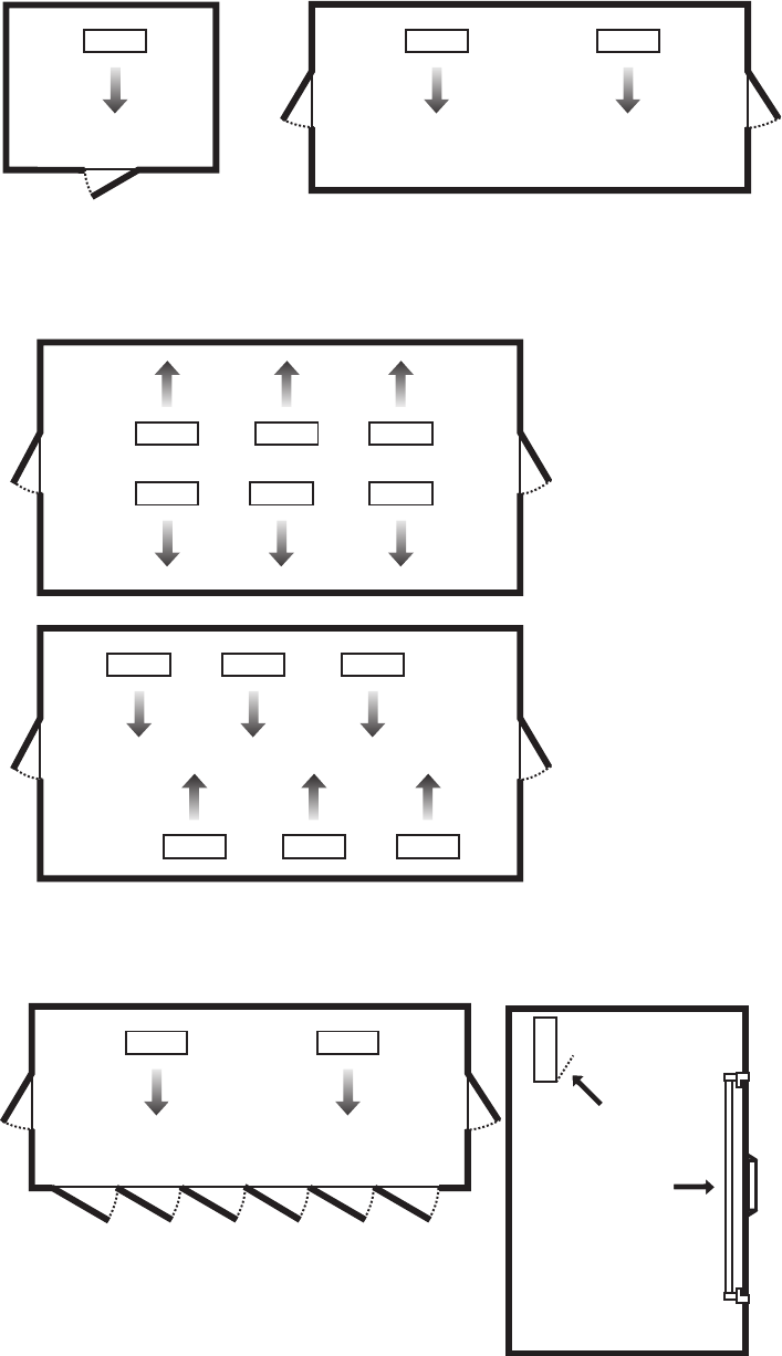
24
Baffle
Glass
Display
Door
Unit Cooler Recommended Coil Replacement
Left
Large cooler or freezer
Right
Large cooler or freezer
Large cooler or freezer where one wall will
not accommodate all required evaporators or
where air-throw distance must be considered.
Note: Always avoid placement of unit coolers
directly above doors and door openings
where low and normal temperature is being
maintained.
Allow sucient space between rear of unit
cooler and wall to permit free return of air.
Refer to unit manufacturers’ catalog for
proper space.
Always trap drain lines individually to prevent
vapor migration. Traps on low temperature
units must be outside of refrigerated enclosures.
Left
Cooler or freezer with glass display doors
Right
Elevation view of glass display door cooler
or freezer. Be sure Air Discharge blows
above, not directly at doors. Provide
bae if door extends above blower level.

25
Line Sizing
The following Tables 22 through 24A on pages 25 through 30
indicate liquid lines and suction lines for all condensing units
for R-22, R-404A, R-134a, and R-507.
When determining the refrigerant line length, be sure to add an
allowance for ttings. See Table 26 on page 31. Total equivalent
length of refrigerant lines is the sum of the actual linear footage
and the allowance for ttings.
Table 22. Recommended Line Sizes for R-134a *
SUCTION LINE SIZE
SUCTION TEMPERATURE
SYSTEM +40˚F +30˚F +20˚F
CAPACITY Equivalent Lengths Equivalent Lengths Equivalent Lengths
BTU/H 25' 50' 75' 100' 150' 200' 25' 50' 75' 100' 150' 200' 25' 50' 75' 100' 150' 200'
1,000 3/8 3/8 3/8 3/8 3/8 1/2 3/8 3/8 3/8 3/8 1/2 1/2 3/8 1/2 1/2 1/2 1/2 5/8
3,000 3/8 1/2 1/2 1/2 5/8 5/8 1/2 1/2 1/2 5/8 5/8 5/8 1/2 5/8 5/8 7/8 7/8 7/8
4,000 1/2 1/2 5/8 5/8 5/8 5/8 1/2 1/2 5/8 5/8 5/8 7/8 5/8 5/8 7/8 7/8 7/8 7/8
6,000 1/2 5/8 5/8 5/8 7/8 7/8 1/2 5/8 5/8 7/8 7/8 7/8 5/8 5/8 7/8 7/8 7/8 7/8
9,000 5/8 5/8 7/8 7/8 7/8 7/8 5/8 7/8 7/8 7/8 7/8 7/8 5/8 7/8 7/8 7/8 7/8 1 1/8
12,000 5/8 7/8 7/8 7/8 7/8 7/8 7/8 7/8 7/8 7/8 1 1/8 1 1/8 7/8 7/8 7/8 1 1/8 1 1/8 1 1/8
15,000 7/8 7/8 7/8 7/8 1 1/8 1 1/8 7/8 7/8 7/8 1 1/8 1 1/8 1 1/8 7/8 7/8 7/8 1 1/8 1 1/8 1 1/8
18,000 7/8 7/8 7/8 7/8 1 1/8 1 1/8 7/8 7/8 1 1/8 1 1/8 1 1/8 1 1/8 7/8 7/8 1 1/8 1 1/8 1 1/8 1 3/8
24,000 7/8 7/8 1 1/8 1 1/8 1 1/8 1 1/8 7/8 1 1/8 1 1/8 1 1/8 1 3/8 1 3/8 7/8 1 1/8 1 1/8 1 1/8 1 3/8 1 3/8
30,000 7/8 1 1/8 1 1/8 1 1/8 1 3/8 1 3/8 7/8 1 1/8 1 1/8 1 3/8 1 3/8 1 3/8 1 1/8 1 1/8 1 1/8 1 3/8 1 3/8 1 3/8
36,000 7/8 1 1/8 1 1/8 1 1/8 1 3/8 1 3/8 1 1/8 1 1/8 1 3/8 1 3/8 1 3/8 1 5/8 1 1/8 1 1/8 1 3/8 1 3/8 1 5/8 1 5/8
42,000 1 1/8 1 1/8 1 1/8 1 3/8 1 3/8 1 3/8 1 1/8 1 1/8 1 3/8 1 3/8 1 5/8 1 5/8 1 1/8 1 3/8 1 3/8 1 3/8 1 5/8 1 5/8
48,000 1 1/8 1 1/8 1 3/8 1 3/8 1 3/8 1 5/8 1 1/8 1 3/8 1 3/8 1 3/8 1 5/8 1 5/8 1 1/8 1 3/8 1 5/8 1 5/8 1 5/8 1 5/8
54,000 1 1/8 1 1/8 1 3/8 1 3/8 1 5/8 1 5/8 1 1/8 1 3/8 1 3/8 1 5/8 1 5/8 1 5/8 1 1/8 1 3/8 1 5/8 1 5/8 1 5/8 2 1/8
60,000 1 1/8 1 3/8 1 3/8 1 3/8 1 5/8 1 5/8 1 1/8 1 3/8 1 3/8 1 5/8 1 5/8 2 1/8 1 3/8 1 3/8 1 5/8 1 5/8 2 1/8 2 1/8
66,000 1 1/8 1 3/8 1 3/8 1 5/8 1 5/8 1 5/8 1 3/8 1 3/8 1 5/8 1 5/8 2 1/8 2 1/8 1 3/8 1 5/8 1 5/8 1 5/8 2 1/8 2 1/8
72,000 1 1/8 1 3/8 1 5/8 1 5/8 1 5/8 2 1/8 1 3/8 1 3/8 1 5/8 1 5/8 2 1/8 2 1/8 1 3/8 1 5/8 2 1/8 2 1/8 2 1/8 2 1/8
78,000 1 1/8 1 3/8 1 5/8 1 5/8 1 5/8 2 1/8 1 3/8 1 5/8 1 5/8 1 5/8 2 1/8 2 1/8 1 3/8 1 5/8 2 1/8 2 1/8 2 1/8 2 1/8
84,000 1 3/8 1 3/8 1 5/8 1 5/8 2 1/8 2 1/8 1 3/8 1 5/8 1 5/8 2 1/8 2 1/8 2 1/8 1 3/8 1 5/8 2 1/8 2 1/8 2 1/8 2 1/8
90,000 1 3/8 1 3/8 1 5/8 1 5/8 2 1/8 2 1/8 1 3/8 1 5/8 1 5/8 2 1/8 2 1/8 2 1/8 1 3/8 1 5/8 2 1/8 2 1/8 2 1/8 2 1/8
120,000 1 3/8 1 5/8 2 1/8 2 1/8 2 1/8 2 1/8 1 5/8 1 5/8 2 1/8 2 1/8 2 1/8 2 5/8 1 5/8 2 1/8 2 1/8 2 1/8 2 5/8 2 5/8
150,000 1 5/8 2 1/8 2 1/8 2 1/8 2 1/8 2 5/8 1 5/8 2 1/8 2 1/8 2 1/8 2 5/8 2 5/8 2 1/8 2 1/8 2 5/8 2 5/8 2 5/8 2 5/8
180,000 1 5/8 2 1/8 2 1/8 2 1/8 2 5/8 2 5/8 1 5/8 2 1/8 2 1/8 2 5/8 2 5/8 2 5/8 2 1/8 2 1/8 2 5/8 2 5/8 2 5/8 3 1/8
210,000 1 5/8 2 1/8 2 1/8 2 1/8 2 5/8 2 5/8 2 1/8 2 1/8 2 5/8 2 5/8 2 5/8 3 1/8 2 1/8 2 1/8 2 5/8 2 5/8 3 1/8 3 1/8
240,000 2 1/8 2 1/8 2 1/8 2 5/8 2 5/8 2 5/8 2 1/8 2 1/8 2 5/8 2 5/8 2 5/8 3 1/8 2 1/8 2 5/8 2 5/8 2 5/8 3 1/8 3 1/8
300,000 2 1/8 2 1/8 2 5/8 2 5/8 2 5/8 3 1/8 2 1/8 2 5/8 2 5/8 2 5/8 3 1/8 3 1/8 2 1/8 2 5/8 3 1/8 3 1/8 3 1/8 3 5/8
360,000 2 1/8 2 5/8 2 5/8 2 5/8 3 1/8 3 1/8 2 1/8 2 5/8 2 5/8 3 1/8 3 1/8 3 5/8 2 5/8 3 1/8 3 5/8 3 5/8 4 1/8 4 1/8
480,000 2 5/8 2 5/8 3 1/8 3 18 3 1/8 3 5/8 2 5/8 3 1/8 3 1/8 3 1/8 3 5/8 3 5/8 3 1/8 3 5/8 3 5/8 4 1/8 5 1/8 5 1/8
600,000 2 5/8 3 1/8 3 1/8 3 1/8 3 5/8 3 5/8 2 5/8 3 1/8 3 1/8 3 5/8 3 5/8 4 1/8 3 1/8 3 5/8 4 1/8 4 1/8 5 1/8 5 1/8
* NOTES:
1. Sizes that are highlighted indicate maximum suction line sizes that should be used for risers. Riser size should not exceed horizontal size.
Properly placed suction traps must also be used for adequate oil return.
All sizes shown are for O.D. Type L copper tubing.
2. Suction line sizes selected at pressure drop equivalent to 2˚F. Reduce estimate of system capacity accordingly.
3. Recommended liquid line size may increase with reverse cycle hot gas systems.
4. Consult factory for R-134a operation at winter conditions below 0° ambient.
Heated and insulated receiver required below 0° ambient.
If system load drops below 40% of design, consideration to installing double suction risers should be made.

26
Table 22A. Recommended Line Sizes for R-134a (continued) *
SUCTION LINE SIZE LIQUID LINE SIZE
SUCTION TEMPERATURE Receiver to
+10˚F 0˚F Expansion Valve SYSTEM
Equivalent Lengths Equivalent Lengths Equivalent Lengths CAPACITY
25' 50' 75' 100' 150' 200' 25' 50' 75' 100' 150' 200' 25' 50' 75' 100' 150' 200' BTU/H
3/8 1/2 1/2 1/2 1/2 5/8 3/8 1/2 1/2 1/2 1/2 5/8 3/8 3/8 3/8 3/8 3/8 3/8 1,000
1/2 5/8 5/8 7/8 7/8 7/8 1/2 5/8 5/8 7/8 7/8 7/8 3/8 3/8 3/8 3/8 3/8 3/8 3,000
5/8 5/8 7/8 7/8 7/8 7/8 5/8 5/8 7/8 7/8 7/8 7/8 3/8 3/8 3/8 3/8 3/8 3/8 4,000
5/8 7/8 7/8 7/8 1 1/8 1 1/8 5/8 7/8 7/8 7/8 7/8 1 1/8 3/8 3/8 3/8 3/8 3/8 3/8 6,000
7/8 7/8 7/8 1 1/8 1 1/8 1 1/8 7/8 7/8 7/8 1 1/8 1 1/8 1 1/8 3/8 3/8 3/8 3/8 3/8 1/2 9,000
7/8 7/8 1 1/8 1 1/8 1 1/8 1 3/8 7/8 1 1/8 1 1/8 1 1/8 1 1/8 1 3/8 3/8 3/8 3/8 3/8 1/2 1/2 12,000
7/8 1 1/8 1 1/8 1 1/8 1 3/8 1 3/8 7/8 1 1/8 1 1/8 1 1/8 1 3/8 1 3/8 3/8 3/8 3/8 1/2 1/2 1/2 15,000
1 1/8 1 1/8 1 1/8 1 3/8 1 3/8 1 3/8 1 1/8 1 1/8 1 1/8 1 3/8 1 3/8 1 3/8 3/8 3/8 1/2 1/2 1/2 1/2 18,000
1 1/8 1 1/8 1 3/8 1 3/8 1 3/8 1 5/8 1 1/8 1 1/8 1 3/8 1 3/8 1 5/8 1 5/8 3/8 1/2 1/2 1/2 1/2 5/8 24,000
1 1/8 1 3/8 1 3/8 1 3/8 1 5/8 1 5/8 1 1/8 1 3/8 1 3/8 1 5/8 1 5/8 1 5/8 1/2 1/2 1/2 1/2 5/8 5/8 30,000
1 3/8 1 3/8 1 3/8 1 5/8 1 5/8 2 1/8 1 3/8 1 3/8 1 5/8 1 5/8 1 5/8 2 1/8 1/2 1/2 1/2 5/8 5/8 5/8 36,000
1 3/8 1 5/8 1 5/8 2 1/8 2 1/8 2 1/8 1 3/8 1 3/8 1 5/8 1 5/8 2 1/8 2 1/8 1/2 1/2 5/8 5/8 5/8 5/8 42,000
1 3/8 1 5/8 1 5/8 2 1/8 2 1/8 2 1/8 1 3/8 1 5/8 1/58 2 1/8 21/8 2 1/8 1/2 5/8 5/8 5/8 5/8 7/8 48,000
1 3/8 1 5/8 2 1/8 2 1/8 2 1/8 2 1/8 1 3/8 1 5/8 1 5/8 2 1/8 2 18 2 1/8 1/2 5/8 5/8 5/8 7/8 7/8 54,000
1 5/8 1 5/8 2 1/8 2 1/8 2 1/8 2 1/8 1 3/8 2 1/8 2 1/8 2 1/8 2 1/8 2 1/8 5/8 5/8 5/8 5/8 7/8 7/8 60,000
1 5/8 2 1/8 2 1/8 2 1/8 2 1/8 2 5/8 1 5/8 2 1/8 2 1/8 2 1/8 2 1/8 2 1/8 5/8 5/8 5/8 7/8 7/8 7/8 66,000
1 5/8 2 1/8 2 1/8 2 1/8 2 5/8 2 5/8 1 5/8 2 1/8 2 1/8 2 1/8 2 1/8 2 5/8 5/8 5/8 7/8 7/8 7/8 7/8 72,000
1 5/8 2 1/8 2 1/8 2 1/8 2 5/8 2 5/8 1 5/8 2 1/8 2 1/8 2 1/8 2 5/8 2 5/8 5/8 5/8 7/8 7/8 7/8 7/8 78,000
1 5/8 2 1/8 2 1/8 2 1/8 2 5/8 2 5/8 1 5/8 2 1/8 2 1/8 2 1/8 2 5/8 2 5/8 5/8 7/8 7/8 7/8 7/8 7/8 84,000
1 5/8 2 1/8 2 1/8 2 5/8 2 5/8 2 5/8 1 5/8 2 1/8 2 1/8 2 1/8 2 5/8 2 5/8 5/8 7/8 7/8 7/8 7/8 7/8 90,000
2 1/8 2 1/8 2 5/8 2 5/8 2 5/8 3 1/8 2 1/8 2 1/8 2 5/8 2 5/8 2 5/8 3 1/8 7/8 7/8 7/8 7/8 7/8 1 1/8 120,000
2 1/8 2 5/8 2 5/8 2 5/8 3 1/8 3 1/8 2 1/8 2 5/8 2 5/8 2 5/8 3 1/8 3 1/8 7/8 7/8 7/8 7/8 1 1/8 1 1/8 150,000
2 1/8 2 5/8 2 5/8 3 1/8 3 1/8 3 1/8 2 1/8 2 5/8 2 5/8 3 1/8 3 1/8 3 1/8 7/8 7/8 7/8 1 1/8 1 1/8 1 1/8 180,000
2 5/8 2 5/8 3 1/8 3 1/8 3 5/8 3 5/8 2 5/8 2 5/8 2 5/8 3 1/8 3 1/8 3 5/8 7/8 7/8 1 1/8 1 1/8 1 1/8 1 1/8 210,000
2 5/8 2 5/8 3 1/8 3 1/8 3 5/8 3 5/8 2 5/8 2 5/8 3 1/8 3 1/8 3 5/8 3 5/8 7/8 1 1/8 1 1/8 1 1/8 1 1/8 1 3/8 240,000
2 5/8 3 1/8 3 1/8 3 5/8 3 5/8 4 1/8 2 5/8 3 1/8 3 1/8 3 5/8 3 5/8 4 1/8 1 1/8 1 1/8 1 1/8 1 1/8 1 3/8 1 3/8 300,000
2 5/8 3 1/8 3 5/8 3 5/8 4 1/8 4 1/8 2 5/8 3 1/8 3 5/8 3 5/8 4 1/8 4 1/8 1 1/8 1 1/8 1 1/8 1 3/8 1 3/8 1 5/8 360,000
3 1/8 3 5/8 3 5/8 4 1/8 5 1/8 5 1/8 3 1/8 3 5/8 3 5/8 4 1/8 5 1/8 5 1/8 1 1/8 1 1/8 1 3/8 1 3/8 1 5/8 1 5/8 480,000
3 1/8 3 5/8 4 1/8 5 1/8 5 1/8 5 1/8 3 1/8 3 5/8 4 1/8 4 1/8 5 1/8 5 1/8 1 3/8 1 3/8 1 3/8 1 5/8 1 5/8 1 5/8 600,000
* NOTES:
1. Sizes that are highlighted indicate maximum suction line sizes that should be used for risers. Riser size should not exceed horizontal size.
Properly placed suction traps must also be used for adequate oil return.
All sizes shown are for O.D. Type L copper tubing.
2. Suction line sizes selected at pressure drop equivalent to 2˚F. Reduce estimate of system capacity accordingly.
3. Recommended liquid line size may increase with reverse cycle hot gas systems.
4. Consult factory for R-134a operation at winter conditions below 0° ambient.
Heated and insulated receiver required below 0° ambient.
If system load drops below 40% of design, consideration to installing double suction risers should be made.

27
Table 23. Recommended Line Sizes for R-22 *
SUCTION LINE SIZE
SUCTION TEMPERATURE
SYSTEM +40˚F +20˚F +10˚F 0˚F
CAPACITY Equivalent Lengths Equivalent Lengths Equivalent Lengths Equivalent
BTU/H 25' 50' 75' 100' 150' 200' 25' 50' 75' 100' 150' 200' 25' 50' 75' 100' 150' 200' 25' 50' 75'
1,000 3/8 3/8 3/8 3/8 3/8 3/8 3/8 3/8 3/8 3/8 3/8 3/8 3/8 3/8 3/8 3/8 3/8 1/2 3/8 3/8 3/8
3,000 3/8 3/8 3/8 1/2 1/2 1/2 3/8 1/2 1/2 1/2 5/8 5/8 3/8 1/2 1/2 1/2 5/8 5/8 1/2 1/2 1/2
4,000 3/8 3/8 1/2 1/2 1/2 1/2 3/8 1/2 1/2 1/2 5/8 5/8 1/2 1/2 1/2 5/8 5/8 5/8 1/2 1/2 5/8
6,000 1/2 1/2 1/2 5/8 5/8 5/8 1/2 1/2 5/8 5/8 5/8 5/8 1/2 5/8 5/8 5/8 7/8 7/8 5/8 5/8 5/8
9,000 1/2 5/8 5/8 5/8 7/8 7/8 1/2 5/8 5/8 5/8 7/8 7/8 5/8 5/8 7/8 7/8 7/8 7/8 5/8 7/8 7/8
12,000 5/8 5/8 5/8 7/8 7/8 7/8 5/8 5/8 7/8 7/8 7/8 7/8 5/8 7/8 7/8 7/8 7/8 7/8 5/8 7/8 7/8
15,000 5/8 5/8 7/8 7/8 7/8 7/8 5/8 7/8 7/8 7/8 7/8 7/8 7/8 7/8 7/8 7/8 1 1/8 1 1/8 7/8 7/8 7/8
18,000 5/8 7/8 7/8 7/8 7/8 1 1/8 5/8 7/8 7/8 7/8 7/8 1 1/8 7/8 7/8 7/8 7/8 1 1/8 1 1/8 7/8 7/8 1 1/8
24,000 5/8 7/8 7/8 7/8 1 1/8 1 1/8 7/8 7/8 7/8 7/8 1 1/8 1 1/8 7/8 7/8 1 1/8 1 1/8 1 1/8 1 1/8 7/8 1 1/8 1 1/8
30,000 7/8 7/8 7/8 1 1/8 1 1/8 1 1/8 7/8 7/8 7/8 1 1/8 1 1/8 1 1/8 7/8 1 1/8 1 1/8 1 1/8 1 1/8 1 3/8 7/8 1 1/8 1 1/8
36,000 7/8 1 1/8 1 1/8 1 1/8 1 1/8 1 3/8 7/8 1 1/8 1 1/8 1 1/8 1 1/8 1 3/8 7/8 1 1/8 1 1/8 1 1/8 1 3/8 1 3/8 1 1/8 1 1/8 1 1/8
42,000 7/8 1 1/8 1 1/8 1 1/8 1 1/8 1 3/8 7/8 1 1/8 1 1/8 1 1/8 1 3/8 1 3/8 1 1/8 1 1/8 1 1/8 1 3/8 1 3/8 1 3/8 1 1/8 1 1/8 1 3/8
48,000 7/8 1 1/8 1 1/8 1 1/8 1 1/8 1 3/8 7/8 1 1/8 1 1/8 1 1/8 1 3/8 1 3/8 1 1/8 1 1/8 1 3/8 1 3/8 1 3/8 1 5/8 1 1/8 1 3/8 1 3/8
54,000 7/8 1 1/8 1 1/8 1 1/8 1 3/8 1 3/8 1 1/8 1 1/8 1 1/8 1 3/8 1 3/8 1 3/8 1 1/8 1 3/8 1 3/8 1 3/8 1 5/8 1 5/8 1 1/8 1 3/8 1 3/8
60,000 7/8 1 1/8 1 1/8 1 1/8 1 3/8 1 3/8 1 1/8 1 1/8 1 1/8 1 3/8 1 3/8 1 5/8 1 1/8 1 3/8 1 3/8 1 3/8 1 5/8 1 5/8 1 1/8 1 3/8 1 3/8
66,000 7/8 1 1/8 1 1/8 1 3/8 1 3/8 1 3/8 1 1/8 1 1/8 1 3/8 1 3/8 1 3/8 1 5/8 1 1/8 1 3/8 1 3/8 1 3/8 1 5/8 1 5/8 1 1/8 1 3/8 1 5/8
72,000 1 1/8 1 1/8 1 1/8 1 3/8 1 3/8 1 3/8 1 1/8 1 3/8 1 3/8 1 3/8 1 5/8 1 5/8 1 1/8 1 3/8 1 3/8 1 5/8 1 5/8 1 5/8 1 3/8 1 3/8 1 5/8
78,000 1 1/8 1 1/8 1 3/8 1 3/8 1 3/8 1 5/8 1 1/8 1 3/8 1 3/8 1 3/8 1 5/8 1 5/8 1 1/8 1 3/8 1 5/8 1 5/8 1 5/8 2 1/8 1 3/8 1 3/8 1 5/8
84,000 1 1/8 1 1/8 1 3/8 1 3/8 1 3/8 1 5/8 1 1/8 1 3/8 1 3/8 1 3/8 1 5/8 1 5/8 1 3/8 1 3/8 1 5/8 1 5/8 1 5/8 2 1/8 1 3/8 1 5/8 1 5/8
90,000 1 1/8 1 3/8 1 3/8 1 3/8 1 5/8 1 5/8 1 1/8 1 3/8 1 3/8 1 5/8 1 5/8 2 1/8 1 3/8 1 3/8 1 5/8 1 5/8 2 1/8 2 1/8 1 3/8 1 5/8 1 5/8
120,000 1 1/8 1 3/8 1 3/8 1 5/8 1 5/8 2 1/8 1 3/8 1 3/8 1 5/8 1 5/8 2 1/8 2 1/8 1 3/8 1 5/8 1 5/8 2 1/8 2 1/8 2 1/8 1 5/8 1 5/8 2 1/8
150,000 1 3/8 1 3/8 1 5/8 1 5/8 2 1/8 2 1/8 1 3/8 1 5/8 1 5/8 2 1/8 2 1/8 2 1/8 1 5/8 1 5/8 1 5/8 2 1/8 2 1/8 2 5/8 1 5/8 2 1/8 2 1/8
180,000 1 3/8 1 5/8 1 5/8 2 1/8 2 1/8 2 1/8 1 3/8 1 5/8 2 1/8 2 1/8 2 1/8 2 1/8 1 5/8 2 1/8 2 1/8 2 1/8 2 5/8 2 5/8 1 5/8 2 1/8 2 1/8
210,000 1 3/8 1 5/8 1 5/8 2 1/8 2 1/8 2 1/8 1 5/8 2 1/8 2 1/8 2 1/8 2 1/8 2 5/8 1 5/8 2 1/8 2 1/8 2 1/8 2 5/8 2 5/8 2 1/8 2 1/8 2 1/8
240,000 1 5/8 1 5/8 2 1/8 2 1/8 2 1/8 2 5/8 1 5/8 2 1/8 2 1/8 2 1/8 2 5/8 2 5/8 2 1/8 2 1/8 2 1/8 2 5/8 2 5/8 2 5/8 2 1/8 2 1/8 2 5/8
300,000 1 5/8 2 1/8 2 1/8 2 1/8 2 5/8 2 5/8 2 1/8 2 1/8 2 1/8 2 5/8 2 5/8 2 5/8 2 1/8 2 1/8 2 5/8 2 5/8 2 5/8 3 1/8 2 1/8 2 5/8 2 5/8
360,000 2 1/8 2 1/8 2 1/8 2 5/8 2 5/8 2 5/8 2 1/8 2 1/8 2 5/8 2 5/8 2 5/8 3 1/8 2 1/8 2 5/8 2 5/8 2 5/8 3 1/8 3 1/8 2 1/8 2 5/8 2 5/8
480,000 2 1/8 2 1/8 2 5/8 2 5/8 2 5/8 3 1/8 2 1/8 2 5/8 2 5/8 2 5/8 3 1/8 3 1/8 2 1/8 2 5/8 2 5/8 3 1/8 3 1/8 3 5/8 2 5/8 2 5/8 3 1/8
600,000 2 1/8 2 5/8 2 5/8 2 5/8 3 1/8 3 1/8 2 1/8 2 5/8 3 1/8 3 1/8 3 1/8 3 5/8 2 5/8 2 5/8 3 1/8 3 1/8 3 5/8 3 5/8 2 5/8 3 1/8 3 1/8
* NOTES:
1. Sizes that are highlighted indicate maximum suction line sizes that should be used for risers. Riser size should not exceed horizontal
size. Properly placed suction traps must also be used for adequate oil return.
All sizes shown are for O.D. Type L copper tubing.
2. Suction line sizes selected at pressure drop equivalent to 2˚F. Reduce estimate of system capacity accordingly.
3. Recommended liquid line size may increase with reverse cycle hot gas systems.
4. If system load drops below 40% of design, consideration to installing double suction risers should be made.

28
Table 23A. Recommended Line Sizes for R-22 (continued) *
SUCTION LINE SIZE LIQUID LINE SIZE
SUCTION TEMPERATURE Receiver to
0˚F -10˚F -20˚F Expansion Valve SYSTEM
Lengths Equivalent Lengths Equivalent Lengths Equivalent Lengths CAPACITY
100' 150' 200' 25' 50' 75' 100' 150' 200' 25' 50' 75' 100' 150' 200' 25' 50' 75' 100' 150' 200' BTU/H
3/8 1/2 1/2 3/8 3/8 3/8 3/8 1/2 1/2 3/8 3/8 3/8 1/2 1/2 1/2 3/8 3/8 3/8 3/8 3/8 3/8 1,000
5/8 5/8 5/8 1/2 1/2 1/2 5/8 5/8 5/8 1/2 1/2 5/8 5/8 5/8 7/8 3/8 3/8 3/8 3/8 3/8 3/8 3,000
5/8 5/8 7/8 1/2 1/2 5/8 5/8 5/8 7/8 1/2 5/8 5/8 5/8 7/8 7/8 3/8 3/8 3/8 3/8 3/8 3/8 4,000
5/8 7/8 7/8 1/2 5/8 5/8 7/8 7/8 7/8 5/8 5/8 7/8 7/8 7/8 7/8 3/8 3/8 3/8 3/8 3/8 3/8 6,000
7/8 7/8 7/8 5/8 7/8 7/8 7/8 7/8 7/8 5/8 7/8 7/8 7/8 1 1/8 1 1/8 3/8 3/8 3/8 3/8 3/8 3/8 9,000
7/8 7/8 1 1/8 7/8 7/8 7/8 7/8 1 18 1 1/8 7/8 7/8 7/8 1 1/8 1 1/8 1 1/8 3/8 3/8 3/8 3/8 3/8 3/8 12,000
7/8 1 1/8 1 1/8 7/8 7/8 7/8 1 1/8 1 1/8 1 1/8 7/8 7/8 1 1/8 1 1/8 1 1/8 1 1/8 3/8 3/8 3/8 3/8 3/8 1/2 15,000
1 1/8 1 1/8 1 1/8 7/8 7/8 1 1/8 1 1/8 1 1/8 1 1/8 7/8 1 1/8 1 1/8 1 1/8 1 1/8 1 3/8 3/8 3/8 3/8 3/8 1/2 1/2 18,000
1 1/8 1 1/8 1 3/8 7/8 1 1/8 1 1/8 1 1/8 1 3/8 1 3/8 7/8 1 1/8 1 1/8 1 3/8 1 3/8 1 3/8 3/8 3/8 1/2 1/2 1/2 1/2 24,000
1 1/8 1 3/8 1 3/8 7/8 1 1/8 1 1/8 1 3/8 1 3/8 1 3/8 1 1/8 1 1/8 1 3/8 1 3/8 1 3/8 1 5/8 3/8 3/8 1/2 1/2 1/2 1/2 30,000
1 3/8 1 3/8 1 3/8 1 1/8 1 1/8 1 3/8 1 3/8 1 3/8 1 5/8 1 1/8 1 3/8 1 3/8 1 3/8 1 5/8 1 5/8 3/8 1/2 1/2 1/2 1/2 1/2 36,000
1 3/8 1 3/8 1 5/8 1 1/8 1 1/8 1 3/8 1 3/8 1 5/8 1 5/8 1 1/8 1 3/8 1 3/8 1 5/8 1 5/8 1 5/8 3/8 1/2 1/2 1/2 1/2 5/8 42,000
1 3/8 1 5/8 1 5/8 1 1/8 1 3/8 1 3/8 1 3/8 1 5/8 1 5/8 1 1/8 1 3/8 1 3/8 1 5/8 1 5/8 2 1/8 1/2 1/2 1/2 1/2 1/2 5/8 48,000
1 3/8 1 5/8 1 5/8 1 1/8 1 3/8 1 3/8 1 5/8 1 5/8 1 5/8 1 3/8 1 3/8 1 5/8 1 5/8 2 1/8 2 1/8 1/2 1/2 1/2 1/2 5/8 5/8 54,000
1 5/8 1 5/8 2 1/8 1 1/8 1 3/8 1 3/8 1 5/8 1 5/8 2 1/8 1 3/8 1 3/8 1 5/8 1 5/8 2 1/8 2 1/8 1/2 1/2 1/2 5/8 5/8 5/8 60,000
1 5/8 1 5/8 2 1/8 1 3/8 1 3/8 1 5/8 1 5/8 1 5/8 2 1/8 1 3/8 1 5/8 1 5/8 1 5/8 2 1/8 2 1/8 1/2 1/2 5/8 5/8 5/8 5/8 66,000
1 5/8 2 1/8 2 1/8 1 3/8 1 3/8 1 5/8 1 5/8 2 1/8 2 1/8 1 3/8 1 5/8 1 5/8 2 1/8 2 1/8 2 1/8 1/2 1/2 5/8 5/8 5/8 5/8 72,000
1 5/8 2 1/8 2 1/8 1 3/8 1 5/8 1 5/8 1 5/8 2 1/8 2 1/8 1 3/8 1 5/8 1 5/8 2 1/8 2 1/8 2 1/8 1/2 1/2 5/8 5/8 5/8 7/8 78,000
1 5/8 2 1/8 2 1/8 1 3/8 1 5/8 1 5/8 2 1/8 2 1/8 2 1/8 1 3/8 1 5/8 2 1/8 2 1/8 2 1/8 2 1/8 1/2 5/8 5/8 5/8 5/8 7/8 84,000
2 1/8 2 1/8 2 1/8 1 3/8 1 5/8 1 5/8 2 1/8 2 1/8 2 1/8 1 3/8 1 5/8 2 1/8 2 1/8 2 1/8 2 1/8 1/2 5/8 5/8 5/8 7/8 7/8 90,000
2 1/8 2 1/8 2 1/8 1 5/8 1 5/8 2 1/8 2 1/8 2 1/8 2 5/8 1 5/8 2 1/8 2 1/8 2 1/8 2 5/8 2 5/8 5/8 5/8 5/8 7/8 7/8 7/8 120,000
2 1/8 2 5/8 2 5/8 1 5/8 2 1/8 2 1/8 2 1/8 2 5/8 2 5/8 2 1/8 2 1/8 2 1/8 2 5/8 2 5/8 2 5/8 5/8 7/8 7/8 7/8 7/8 7/8 150,000
2 1/8 2 5/8 2 5/8 1 5/8 2 1/8 2 1/8 2 5/8 2 5/8 2 5/8 2 1/8 2 1/8 2 5/8 2 5/8 2 5/8 3 1/8 5/8 7/8 7/8 7/8 7/8 1 1/8 180,000
2 5/8 2 5/8 2 5/8 2 1/8 2 1/8 2 5/8 2 5/8 2 5/8 2 5/8 2 1/8 2 5/8 2 5/8 2 5/8 3 1/8 3 1/8 7/8 7/8 7/8 7/8 7/8 1 1/8 210,000
2 5/8 2 5/8 3 1/8 2 1/8 2 1/8 2 5/8 2 5/8 2 5/8 3 1/8 2 1/8 2 5/8 2 5/8 2 5/8 3 1/8 3 1/8 7/8 7/8 7/8 7/8 1 1/8 1 1/8 240,000
2 5/8 3 1/8 3 1/8 2 1/8 2 5/8 2 5/8 2 5/8 3 1/8 3 1/8 2 1/8 2 5/8 3 1/8 3 1/8 3 1/8 3 5/8 7/8 7/8 1 1/8 1 1/8 1 1/8 1 1/8 300,000
3 1/8 3 1/8 3 1/8 2 1/8 2 5/8 2 5/8 3 1/8 3 1/8 3 5/8 2 5/8 2 5/8 3 1/8 3 1/8 3 5/8 3 5/8 7/8 7/8 1 18 1 1/8 1 1/8 1 1/8 360,000
3 1/8 3 5/8 3 5/8 2 5/8 3 1/8 3 1/8 3 1/8 3 5/8 3 5/8 2 5/8 3 1/8 3 5/8 3 5/8 3 5/8 4 1/8 1 1/8 1 1/8 1 1/8 1 1/8 1 3/8 1 3/8 480,000
3 5/8 3 5/8 4 1/8 2 5/8 3 1/8 3 1/8 3 5/8 3 5/8 4 1/8 3 1/8 3 1/8 3 5/8 3 5/8 4 1/8 4 1/8 1 1/8 1 1/8 1 1/8 1 3/8 1 3/8 1 3/8 600,000
* NOTES:
1. Sizes that are highlighted indicate maximum suction line sizes that should be used for risers. Riser size should not exceed horizontal size.
Properly placed suction traps must also be used for adequate oil return.
All sizes shown are for O.D. Type L copper tubing.
2. Suction line sizes selected at pressure drop equivalent to 2˚F. Reduce estimate of system capacity accordingly.
3. Recommended liquid line size may increase with reverse cycle hot gas systems.
4. If system load drops below 40% of design, consideration to installing double suction risers should be made.

29
Table 24. Recommended Line Sizes for R-404A and R-507 *
SUCTION LINE SIZE
SUCTION TEMPERATURE
SYSTEM +20˚F +10˚F -10˚F -20˚F
CAPACITY Equivalent Lengths Equivalent Lengths Equivalent Lengths Equivalent
BTU/H 25' 50' 75' 100' 150' 200' 25' 50' 75' 100' 150' 200' 25' 50' 75' 100' 150' 200' 25' 50' 75'
1,000 3/8 3/8 3/8 3/8 3/8 3/8 3/8 3/8 3/8 3/8 3/8 1/2 3/8 3/8 3/8 1/2 1/2 1/2 3/8 3/8 1/2
3,000 3/8 3/8 1/2 1/2 1/2 5/8 3/8 1/2 1/2 1/2 5/8 5/8 1/2 1/2 5/8 5/8 5/8 7/8 1/2 1/2 5/8
4,000 3/8 1/2 1/2 1/2 5/8 5/8 1/2 1/2 1/2 5/8 5/8 7/8 1/2 5/8 5/8 5/8 7/8 7/8 1/2 5/8 5/8
6,000 1/2 1/2 5/8 5/8 7/8 7/8 1/2 1/2 5/8 5/8 7/8 7/8 1/2 5/8 5/8 7/8 7/8 7/8 5/8 5/8 7/8
9,000 5/8 5/8 7/8 7/8 7/8 7/8 5/8 5/8 7/8 7/8 7/8 7/8 5/8 7/8 7/8 7/8 7/8 1 1/8 5/8 7/8 7/8
12,000 5/8 7/8 7/8 7/8 7/8 7/8 5/8 7/8 7/8 7/8 7/8 1 1/8 7/8 7/8 7/8 7/8 1 1/8 1 1/8 7/8 7/8 7/8
15,000 5/8 7/8 7/8 7/8 7/8 1 1/8 7/8 7/8 7/8 7/8 1 1/8 1 1/8 7/8 7/8 7/8 1 1/8 1 1/8 1 1/8 7/8 7/8 1 1/8
18,000 7/8 7/8 7/8 7/8 1 1/8 1 1/8 7/8 7/8 7/8 1 1/8 1 1/8 1 1/8 7/8 7/8 1 1/8 1 1/8 1 1/8 1 3/8 7/8 1 1/8 1 1/8
24,000 7/8 7/8 7/8 1 1/8 1 1/8 1 1/8 7/8 1 1/8 1 1/8 1 1/8 1 1/8 1 3/8 7/8 1 1/8 1 1/8 1 1/8 1 3/8 1 3/8 1 1/8 1 1/8 1 1/8
30,000 7/8 7/8 1 1/8 1 1/8 1 1/8 1 3/8 7/8 1 1/8 1 1/8 1 1/8 1 3/8 1 3/8 1 1/8 1 1/8 1 1/8 1 3/8 1 3/8 1 3/8 1 1/8 1 1/8 1 1/8
36,000 7/8 1 1/8 1 1/8 1 1/8 1 3/8 1 3/8 1 1/8 1 1/8 1 1/8 1 3/8 1 3/8 1 3/8 1 1/8 1 1/8 1 3/8 1 3/8 1 3/8 1 5/8 1 1/8 1 1/8 1 3/8
42,000 1 1 /8 1 1/8 1 1/8 1 3/8 1 3/8 1 3/8 1 1/8 1 1/8 1 3/8 1 3/8 1 3/8 1 5/8 1 1/8 1 3/8 1 3/8 1 3/8 1 5/8 1 5/8 1 1/8 1 3/8 1 3/8
48,000 1 1/8 1 1/8 1 3/8 1 3/8 1 3/8 1 3/8 1 1/8 1 1/8 1 3/8 1 3/8 1 5/8 1 5/8 1 1/8 1 3/8 1 3/8 1 3/8 1 5/8 1 5/8 1 1/8 1 3/8 1 3/8
54,000 1 1/8 1 1/8 1 3/8 1 3/8 1 3/8 1 5/8 1 1/8 1 3/8 1 3/8 1 3/8 1 5/8 1 5/8 1 3/8 1 3/8 1 3/8 1 5/8 1 5/8 1 5/8 1 3/8 1 3/8 1 5/8
60,000 1 1/8 1 1/8 1 3/8 1 3/8 1 5/8 1 5/8 1 1/8 1 3/8 1 3/8 1 5/8 1 5/8 1 5/8 1 3/8 1 3/8 1 5/8 1 5/8 1 5/8 2 1/8 1 3/8 1 3/8 1 5/8
66,000 1 1/8 1 3/8 1 3/8 1 3/8 1 5/8 1 5/8 1 1/8 1 3/8 1 3/8 1 5/8 1 5/8 1 5/8 1 3/8 1 5/8 1 5/8 1 5/8 1 5/8 1 5/8 1 3/8 1 5/8 1 5/8
72,000 1 1/8 1 3/8 1 3/8 1 5/8 1 5/8 1 5/8 1 1/8 1 3/8 1 5/8 1 5/8 1 5/8 1 5/8 1 3/8 1 5/8 1 5/8 1 5/8 1 5/8 1 5/8 1 3/8 1 5/8 1 5/8
78,000 1 1/8 1 3/8 1 3/8 1 5/8 1 5/8 2 1/8 1 3/8 1 3/8 1 5/8 1 5/8 1 5/8 2 1/8 1 3/8 1 5/8 1 5/8 1 5/8 1 5/8 2 1/8 1 5/8 1 5/8 1 5/8
84,000 1 1/8 1 3/8 1 5/8 1 5/8 1 5/8 2 1/8 1 3/8 1 3/8 1 5/8 1 5/8 2 1/8 2 1/8 1 3/8 1 5/8 1 5/8 1 5/8 2 1/8 2 1/8 1 5/8 1 5/8 1 5/8
90,000 1 3/8 1 3/8 1 5/8 1 5/8 2 1/8 2 1/8 1 3/8 1 5/8 1 5/8 1 5/8 2 1/8 2 1/8 1 5/8 1 5/8 1 5/8 2 1/8 2 1/8 2 5/8 1 5/8 1 5/8 2 1/8
120,000 1 3/8 1 5/8 1 5/8 2 1/8 2 1/8 2 1/8 1 3/8 1 5/8 2 1/8 2 1/8 2 1/8 2 1/8 1 5/8 2 1/8 2 1/8 2 1/8 2 5/8 2 5/8 1 5/8 2 1/8 2 1/8
150,000 1 5/8 1 5/8 2 1/8 2 1/8 2 1/8 2 1/8 1 5/8 2 1/8 2 1/8 2 1/8 2 1/8 2 5/8 2 1/8 2 1/8 2 1/8 2 5/8 2 5/8 2 5/8 2 1/8 2 1/8 2 1/8
180,000 1 5/8 2 1/8 2 1/8 2 1/8 2 1/8 2 5/8 1 5/8 2 1/8 2 1/8 2 1/8 2 5/8 2 5/8 2 1/8 2 1/8 2 5/8 2 5/8 2 5/8 3 1/8 2 1/8 2 1/8 2 5/8
210,000 1 5/8 2 1/8 2 1/8 2 1/8 2 5/8 2 5/8 2 1/8 2 1/8 2 1/8 2 5/8 2 5/8 2 5/8 2 1/8 2 1/8 2 5/8 2 5/8 3 1/8 3 1/8 2 1/8 2 5/8 2 5/8
240,000 1 5/8 2 1/8 2 1/8 2 1/8 2 5/8 2 5/8 2 1/8 2 1/8 2 5/8 2 5/8 2 5/8 2 5/8 2 1/8 2 5/8 2 5/8 2 5/8 3 1/8 3 1/8 2 1/8 2 5/8 2 5/8
300,000 2 1/8 2 1/8 2 5/8 2 5/8 2 5/8 3 1/8 2 1/8 2 5/8 2 5/8 2 5/8 3 1/8 3 1/8 2 5/8 2 5/8 2 5/8 3 1/8 3 1/8 3 5/8 2 5/8 2 5/8 2 5/8
360,000 2 1/8 2 1/8 2 5/8 2 5/8 3 1/8 3 1/8 2 1/8 2 5/8 2 5/8 2 5/8 3 1/8 3 1/8 2 5/8 2 5/8 3 1/8 3 1/8 3 5/8 3 5/8 2 5/8 2 5/8 3 1/8
480,000 2 1/8 2 5/8 2 5/8 3 1/8 3 1/8 3 5/8 2 5/8 2 5/8 2 5/8 2 5/8 3 5/8 3 5/8 2 5/8 3 1/8 3 1/8 3 5/8 3 5/8 4 1/8 2 5/8 3 1/8 3 1/8
600,000 2 5/8 2 5/8 3 1/8 3 1/8 3 5/8 3 5/8 2 5/8 2 5/8 3 1/8 3 1/8 3 5/8 3 5/8 3 1/8 3 1/8 3 1/8 3 5/8 4 1/8 4 1/8 3 1/8 3 1/8 3 1/8
* NOTES:
1. Sizes that are highlighted indicate maximum suction line sizes that should be used for risers. Riser size should not exceed horizontal size.
Properly placed suction traps must also be used for adequate oil return.
All sizes shown are for O.D. Type L copper tubing.
2. Suction line sizes selected at pressure drop equivalent to 2˚F. Reduce estimate of system capacity accordingly.
3. Recommended liquid line size may increase with reverse cycle hot gas systems.
4. If system load drops below 40% of design, consideration to installing double suction risers should be made.

30
Table 24A. Recommended Line Sizes for R-404A and R-507 (continued) *
SUCTION LINE SIZE LIQUID LINE SIZE
SUCTION TEMPERATURE Receiver to
-20˚F -30˚F -40˚F Expansion Valve SYSTEM
Lengths Equivalent Lengths Equivalent Lengths Equivalent Lengths CAPACITY
100' 150' 200' 25' 50' 75' 100' 150' 200' 25' 50' 75' 100' 150' 200' 25' 50' 75' 100' 150' 200' BTU/H
1/2 1/2 1/2 3/8 3/8 1/2 1/2 1/2 5/8 3/8 1/2 1/2 1/2 5/8 5/8 3/8 3/8 3/8 3/8 3/8 3/8 1,000
5/8 7/8 7/8 1/2 1/2 5/8 5/8 7/8 7/8 1/2 1/2 5/8 5/8 7/8 7/8 3/8 3/8 3/8 3/8 3/8 3/8 3,000
7/8 7/8 7/8 5/8 5/8 5/8 7/8 7/8 7/8 1/2 5/8 5/8 7/8 7/8 7/8 3/8 3/8 3/8 3/8 3/8 3/8 4,000
7/8 7/8 7/8 5/8 5/8 7/8 7/8 7/8 7/8 5/8 5/8 7/8 7/8 7/8 1 1/8 3/8 3/8 3/8 3/8 3/8 3/8 6,000
7/8 1 1/8 1 1/8 5/8 7/8 7/8 7/8 1 1/8 1 1/8 5/8 7/8 7/8 7/8 1 1/8 1 1/8 3/8 3/8 3/8 3/8 3/8 3/8 9,000
1 1/8 1 1/8 1 1/8 7/8 7/8 7/8 1 1/8 1 1/8 1 1/8 7/8 7/8 7/8 1 1/8 1 1/8 1 1/8 3/8 3/8 3/8 3/8 3/8 1/2 12,000
1 1/8 1 1/8 1 3/8 7/8 7/8 1 1/8 1 1/8 1 1/8 1 3/8 7/8 7/8 1 1/8 1 1/8 1 1/8 1 3/8 3/8 3/8 3/8 3/8 1/2 1/2 15,000
1 1/8 1 3/8 1 3/8 7/8 1 1/8 1 1/8 1 1/8 1 3/8 1 3/8 7/8 1 1/8 1 1/8 1 1/8 1 3/8 1 3/8 3/8 3/8 3/8 1/2 1/2 1/2 18,000
1 3/8 1 3/8 1 3/8 1 1/8 1 1/8 1 1/8 1 3/8 1 3/8 1 3/8 1 1/8 1 1/8 1 1/8 1 3/8 1 3/8 1 3/8 3/8 3/8 1/2 1/2 1/2 1/2 24,000
1 3/8 1 3/8 1 5/8 1 1/8 1 1/8 1 3/8 1 3/8 1 3/8 1 5/8 1 1/8 1 1/8 1 3/8 1 3/8 1 3/8 1 5/8 3/8 1/2 1/2 1/2 1/2 1/2 30,000
1 3/8 1 3/8 1 5/8 1 1/8 1 3/8 1 3/8 1 3/8 1 3/8 1 5/8 1 1/8 1 3/8 1 3/8 1 3/8 1 5/8 1 5/8 1/2 1/2 1/2 1/2 1/2 5/8 36,000
1 5/8 1 5/8 1 5/8 1 1/8 1 3/8 1 3/8 1 3/8 1 5/8 1 5/8 1 1/8 1 3/8 1 3/8 1 3/8 1 5/8 1 5/8 1/2 1/2 1/2 1/2 5/8 5/8 42,000
1 5/8 1 5/8 1 5/8 1 1/8 1 3/8 1 3/8 1 3/8 1 5/8 1 5/8 1 1/8 1 3/8 1 3/8 1 3/8 1 5/8 1 5/8 1/2 1/2 1/2 5/8 5/8 5/8 48,000
1 5/8 1 5/8 1 5/8 1 3/8 1 3/8 1 3/8 1 5/8 1 5/8 2 1/8 1 3/8 1 3/8 1 3/8 1 5/8 1 5/8 2 1/8 1/2 1/2 1/2 5/8 5/8 5/8 54,000
1 5/8 1 5/8 2 1/8 1 3/8 1 3/8 1 5/8 1 5/8 1 5/8 2 1/8 1 3/8 1 3/8 1 5/8 1 5/8 1 5/8 2 1/8 1/2 1/2 5/8 5/8 5/8 5/8 60,000
1 5/8 1 5/8 2 1/8 1 3/8 1 5/8 1 5/8 1 5/8 1 5/8 2 1/8 1 3/8 1 5/8 1 5/8 1 5/8 1 5/8 2 1/8 1/2 1/2 5/8 5/8 5/8 5/8 66,000
1 5/8 1 5/8 2 1/8 1 3/8 1 5/8 1 5/8 1 5/8 1 5/8 2 1/8 1 3/8 1 5/8 1 5/8 1 5/8 1 5/8 2 1/8 1/2 5/8 5/8 5/8 5/8 5/8 72,000
1 5/8 2 1/8 2 1/8 1 5/8 1 5/8 1 5/8 1 5/8 2 1/8 2 1/8 1 5/8 1 5/8 1 5/8 1 5/8 2 1/8 2 1/8 5/8 5/8 5/8 5/8 5/8 7/8 78,000
2 1/8 2 1/8 2 1/8 1 5/8 1 5/8 1 5/8 2 1/8 2 1/8 2 1/8 1 5/8 1 5/8 1 5/8 2 1/8 2 1/8 2 1/8 5/8 5/8 5/8 5/8 7/8 7/8 84,000
2 1/8 2 1/8 2 5/8 1 5/8 2 1/8 2 1/8 2 1/8 2 1/8 2 5/8 1 5/8 1 5/8 2 1/8 2 1/8 2 1/8 2 5/8 5/8 5/8 5/8 7/8 7/8 7/8 90,000
2 1/8 2 5/8 2 5/8 1 5/8 2 1/8 2 1/8 2 1/8 2 5/8 2 5/8 1 5/8 2 1/8 2 1/8 2 1/8 2 5/8 2 5/8 5/8 5/8 7/8 7/8 7/8 7/8 120,000
2 5/8 2 5/8 2 5/8 2 1/8 2 1/8 2 1/8 2 5/8 2 5/8 2 5/8 2 1/8 2 1/8 2 5/8 2 5/8 2 5/8 2 5/8 5/8 7/8 7/8 7/8 7/8 1 1/8 150,000
2 5/8 2 5/8 3 1/8 2 1/8 2 1/8 2 5/8 2 5/8 2 5/8 3 1/8 2 1/8 2 1/8 2 5/8 2 5/8 2 5/8 3 1/8 7/8 7/8 7/8 7/8 1 1/8 1 1/8 180,000
2 5/8 3 1/8 3 1/8 2 1/8 2 5/8 2 5/8 2 5/8 3 1/8 3 1/8 2 1/8 2 5/8 2 5/8 2 5/8 3 1/8 3 1/8 7/8 7/8 7/8 1 1/8 1 1/8 1 1/8 210,000
2 5/8 3 1/8 3 1/8 2 5/8 2 5/8 2 5/8 3 1/8 3 1/8 3 5/8 2 5/8 2 5/8 2 5/8 3 1/8 3 1/8 3 5/8 7/8 7/8 1 1/8 1 1/8 1 1/8 1 3/8 240,000
3 1/8 3 5/8 3 5/8 2 5/8 2 5/8 3 1/8 3 1/8 3 5/8 4 1/8 2 5/8 2 5/8 3 1/8 3 5/8 3 5/8 4 1/8 7/8 1 1/8 1 1/8 1 1/8 1 3/8 1 3/8 300,000
3 5/8 3 5/8 4 1/8 2 5/8 3 1/8 3 1/8 3 5/8 3 5/8 4 1/8 2 5/8 3 1/8 3 5/8 3 5/8 4 1/8 4 1/8 1 1/8 1 1/8 1 1/8 1 3/8 1 3/8 1 5/8 360,000
3 5/8 3 5/8 4 1/8 3 1/8 3 5/8 3 5/8 4 1/8 4 1/8 4 1/8 3 1/8 3 5/8 3 5/8 4 1/8 4 1/8 4 1/8 1 1/8 1 1/8 1 3/8 1 3/8 1 5/8 1 5/8 480,000
3 5/8 3 5/8 4 1/8 3 1/8 3 5/8 3 5/8 4 1/8 4 1/8 5 1/8 3 1/8 3 5/8 3 5/8 4 1/8 4 1/8 5 1/8 1 1/8 1 3/8 1 3/8 1 5/8 1 5/8 1 5/8 600,000
* NOTES:
1. Sizes that are highlighted indicate maximum suction line sizes that should be used for risers. Riser size should not exceed horizontal size.
Properly placed suction traps must also be used for adequate oil return.
All sizes shown are for O.D. Type L copper tubing.
2. Suction line sizes selected at pressure drop equivalent to 2˚F. Reduce estimate of system capacity accordingly.
3. Recommended liquid line size may increase with reverse cycle hot gas systems.
4. If system load drops below 40% of design, consideration to installing double suction risers should be made.
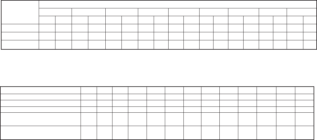
31
Table 26. Equivalent Feet of Pipe Due to Valve and Fitting Friction
Copper Tube, O.D., Type “L” 1/2 5/8 7/8 1 1/8 1 3/8 1 5/8 2 1/8 2 5/8 3 1/8 3 5/8 4 1/8 5 1/8 6 1/8
Globe Valve (Open) 14 16 22 28 36 42 57 69 83 99 118 138 168
Angle Valve (Open) 7 9 12 15 18 21 28 34 42 49 57 70 83
90˚ Turn Through Tee 3 4 5 6 8 9 12 14 17 20 22 28 34
Tee (Straight Through)
or Sweep Below .75 1 1.5 2 2.5 3 3.5 4 5 6 7 9 11
90˚ Elbow or Reducing
Tee (Straight Through) 1 2 2 3 4 4 5 7 8 10 12 14 16
Table 25. Pressure Loss of Liquid Refrigerants in Liquid Line Risers (Expressed in Pressure Drop, PSIG,
and Subcooling Loss, ˚F).
Liquid Line Rise in Feet
10' 15' 20' 25' 30' 40' 50' 75' 100'
Refrigerant PSIG ˚F PSIG ˚F PSIG ˚F PSIG ˚F PSIG ˚F PSIG ˚F PSIG ˚F PSIG ˚F PSIG ˚F
R-22 4.8 1.6 7.3 2.3 9.7 3.1 12.1 3.8 14.5 4.7 19.4 6.2 24.2 8.0 36.3 12.1 48.4 16.5
R-134a 4.9 2.0 7.4 2.9 9.8 4.1 12.3 5.2 14.7 6.3 19.7 8.8 24.6 11.0 36.8 17.0 49.1 23.7
R-507, R-404A 4.1 1.1 6.1 1.6 8.2 2.1 10.2 2.7 12.2 3.3 16.3 4.1 20.4 5.6 30.6 8.3 40.8 11.8
Based on 110˚F liquid temperature at bottom of riser.

32
Table 27. Recommended Remote Condenser Line Sizes
R-134a R-22 R507 & R-404A
Liquid Line Liquid Line Liquid Line
Net Total Discharge Cond. to Discharge Cond. to Discharge Cond. to
Evaporator Equiv. Line Receiver Line Receiver Line Receiver
Capacity Length (O.D.) (O.D.) (O.D.) (O.D.) (O.D.) (O.D.)
3,000 50 3/8 3/8 3/8 3/8 3/8 3/8
100 3/8 3/8 3/8 3/8 3/8 3/8
6,000 50 1/2 3/8 3/8 3/8 1/2 3/8
100 1/2 3/8 1/2 3/8 1/2 3/8
9,000 50 1/2 3/8 1/2 3/8 1/2 3/8
100 5/8 3/8 1/2 3/8 1/2 3/8
12,000 50 5/8 3/8 1/2 3/8 1/2 3/8
100 5/8 1/2 5/8 3/8 5/8 1/2
18,000 50 5/8 1/2 5/8 3/8 5/8 1/2
100 7/8 1/2 5/8 3/8 7/8 1/2
24,000 50 7/8 1/2 5/8 3/8 5/8 1/2
100 7/8 1/2 7/8 1/2 7/8 5/8
36,000 50 7/8 1/2 7/8 1/2 7/8 5/8
100 1 1/8 5/8 7/8 5/8 7/8 7/8
48,000 50 7/8 5/8 7/8 5/8 7/8 5/8
100 1 1/8 7/8 7/8 7/8 1 1/8 7/8
60,000 50 1 1/8 5/8 7/8 5/8 7/8 7/8
100 1 1/8 7/8 1 1/8 7/8 1 1/8 7/8
72,000 50 1 1/8 7/8 7/8 7/8 1 1/8 7/8
100 1 3/8 7/8 1 1/8 7/8 1 1/8 1 1/8
90,000 50 1 1/8 7/8 1 1/8 7/8 1 1/8 7/8
100 1 3/8 1 1/8 1 1/8 7/8 1 1/8 1 1/8
120,000 50 1 3/8 7/8 1 1/8 7/8 1 1/8 1 1/8
100 1 5/8 1 1/8 1 3/8 1 1/8 1 3/8 1 3/8
180,000 50 1 5/8 1 1/8 1 3/8 1 1/8 1 3/8 1 3/8
100 1 5/8 1 3/8 1 5/8 1 3/8 1 5/8 1 5/8
240,000 50 1 5/8 1 3/8 1 3/8 1 3/8 1 5/8 1 3/8
100 2 1/8 1 5/8 1 5/8 1 3/8 2 1/8 1 5/8
300,000 50 2 1/8 1 3/8 1 5/8 1 3/8 1 5/8 1 5/8
100 2 1/8 1 5/8 2 1/8 1 5/8 2 1/8 2 1/8
360,000 50 2 1/8 1 5/8 1 5/8 1 5/8 2 1/8 1 5/8
100 2 1/8 2 1/8 2 1/8 2 1/8 2 1/8 2 1/8
480,000 50 2 1/8 2 1/8 2 1/8 1 5/8 2 1/8 2 1/8
100 2 5/8 2 1/8 2 1/8 2 1/8 2 1/8 2 5/8
600,000 50 2 5/8 2 1/8 2 1/8 2 1/8 2 1/8 2 1/8
100 2 5/8 2 5/8 2 5/8 2 5/8 2 5/8 2 5/8
720,000 50 2 5/8 2 1/8 2 1/8 2 1/8 2 1/8 2 5/8
100 3 1/8 2 5/8 2 5/8 2 5/8 2 5/8 3 1/8
840,000 50 2 5/8 2 5/8 2 1/8 2 1/8 2 5/8 2 5/8
100 3 1/8 3 1/8 2 5/8 2 5/8 2 5/8 3 1/8
960,000 50 2 5/8 2 5/8 2 5/8 2 5/8 2 5/8 2 5/8
100 3 1/8 3 1/8 2 5/8 3 1/8 3 1/8 3 5/8
1,080,000 50 3 1/8 2 5/8 2 5/8 2 5/8 2 5/8 3 1/8
100 3 1/8 3 1/8 3 1/8 3 1/8 3 1/8 3 5/8
1,200,000 50 3 1/8 2 5/8 2 5/8 2 5/8 2 5/8 3 1/8
100 3 5/8 3 5/8 3 1/8 3 1/8 3 5/8 4 1/8
1,440,000 50 3 1/8 3 1/8 2 5/8 3 1/8 3 1/8 3 5/8
100 3 5/8 3 5/8 3 1/8 3 5/8 3 5/8 4 1/8
1,680,000 50 3 5/8 3 1/8 3 1/8 3 1/8 3 1/8 3 5/8
100 4 1/8 4 1/8 3 5/8 3 5/8 3 5/8 4 1/8

33
Table 28. Weight of Refrigerants in Copper Lines During Operation (Pounds per 100 lineal feet of type "L" tubing).
Line Size Suction Line at Suction Temperature
O.D. Liquid Hot Gas
in Inches Refrigerant Line Line -40˚F -20˚F 0˚F +20˚F +40˚F
134a 4.0 .15 .01 .01 .02 .04 .06
3/8 22 3.9 .22 .02 .03 .04 .06 .08
R507, 404A 3.4 .31 .03 .04 .06 .09 .13
134a 7.4 .30 .01 .03 .04 .07 .11
1/2 22 7.4 .41 .03 .05 .07 .11 .15
R507, 404A 6.4 .58 .04 .07 .13 .16 .24
134a 11.9 .47 .02 .05 .07 .12 .17
5/8 22 11.8 .65 .05 .08 .12 .17 .25
R507, 404A 10.3 .93 .07 .11 .17 .25 .35
134a 24.7 .99 .05 .10 .15 .24 .36
7/8 22 24.4 1.35 .10 .16 .24 .36 .51
R507, 404A 21.2 1.92 .15 .23 .37 .51 .72
134a 42.2 1.70 .08 .17 .26 .41 .60
1 1/8 22 41.6 2.30 .17 .28 .42 .61 .87
R507, 404A 36.1 3.27 .26 .39 .63 .86 1.24
134a 64.2 2.57 .14 .26 .40 .61 1.91
1 3/8 22 63.5 3.50 .27 .42 .64 .93 1.33
R507, 404A 55.0 4.98 .40 .58 .95 1.32 1.87
134a 90.9 3.65 .20 .37 .57 .87 1.30
1 5/8 22 90.0 4.96 .37 .59 .90 1.33 1.88
R507, 404A 78.0 7.07 .56 .82 1.35 1.86 2.64
134a 158 6.34 .34 .64 .98 1.51 2.24
2 1/8 22 156 8.61 .65 1.03 1.57 2.30 3.26
R507, 404A 134 12.25 .98 1.43 2.35 3.23 4.58
134a 244 9.78 .52 .99 1.51 2.32 3.47
2 5/8 22 241 13.70 1.01 1.59 2.42 3.54 5.03
R507, 404A 209 18.92 1.51 2.21 3.62 5.00 7.07
134a 348 13.97 .75 1.41 2.16 3.31 4.96
3 1/8 22 344 18.95 1.44 2.28 3.45 5.05 7.18
R507, 404A 298 27.05 2.16 3.15 5.17 7.14 9.95
134a 471 18.90 .99 1.91 2.92 4.48 6.69
3 5/8 22 465 25.60 1.94 3.08 4.67 6.83 9.74
R507, 404A 403 36.50 2.92 4.25 6.97 19.65 13.67
134a 612 24.56 1.29 2.49 3.81 5.84 8.75
4 1/8 22 605 33.40 2.53 4.01 6.08 8.90 12.70
R507, 404A 526 47.57 3.80 5.55 9.09 12.58 17.80

34
Table 29.
Fahrenheit – Celsius Temperature Conversion Chart
The number in bold type-face in the center column refers to
the temperature, either Celsius or Fahrenheit, which is to be
converted to the other scale. If converting Fahrenheit to Celsius
the equivalent temperature will be found in the left column. If
converting Celsius to Fahrenheit, the equivalent temperature will
be found in the column on the right.
Temperature Temperature Temperature Temperature
Celsius ºC. or ºF. Fahrenheit Celsius ºC. or ºF. Fahrenheit Celsius ºC. or ºF. Fahrenheit Celsius ºC. or ºF. Fahrenheit
-40.0 -40 -40.0 -6.7 +20 +68.0 +26.7 +80 +176.0 +60.0 +140 +284.0
-39.4 -39 -38.2 -6.1 +21 +69.8 +27.2 +81 +177.8 +60.6 +141 +285.8
-38.9 -38 -36.4 -5.5 +22 +71.6 +27.8 +82 +179.6 +61.1 +142 +287.6
-38.3 -37 -34.6 -5.0 +23 +73.4 +28.3 +83 +181.4 +61.7 +143 +289.4
-37.8 -36 -32.8 -4.4 +24 +75.2 +28.9 +84 +183.2 +62.2 +144 +291.2
-37.2 -35 -31.0 -3.9 +25 +77.0 +29.4 +85 +185.0 +62.8 +145 +293.0
-36.7 -34 -29.2 -3.3 +26 +78.8 +30.0 +86 +186.8 +63.3 +146 +294.8
-36.1 -33 -27.4 -2.8 +27 +80.6 +30.6 +87 +186.6 +63.9 +147 +296.6
-35.6 -32 -25.6 -2.2 +28 +82.4 +31.1 +88 +190.4 +64.4 +148 +298.4
-35.0 -31 -23.8 -1.7 +29 +84.2 +31.7 +89 +192.2 +65.0 +149 +300.2
-34.4 -30 -22.0 -1.1 +30 +86.0 +32.2 +90 +194.0 +65.6 +150 +302.0
-33.9 -29 -20.2 -0.6 +31 +87.8 +32.8 +91 +195.8 +66.1 +151 +303.8
-33.3 -28 -18.4 0 +32 +89.6 +33.3 +92 +197.6 +66.7 +152 +305.6
-32.8 -27 -16.6 +0.6 +33 +91.4 +33.9 +93 +199.4 +67.2 +153 +307.4
-32.2 -26 -14.8 +1.1 +34 +93.2 +34.4 +94 +201.2 +67.8 +154 +309.2
-31.7 -25 -13.0 +1.7 +35 +95.0 +35.0 +95 +203.0 +68.3 +155 +311.0
-31.1 -24 -11.2 +2.2 +36 +96.8 +35.6 +96 +204.8 +68.9 +156 +312.8
-30.6 -23 -9.4 +2.8 +37 +98.6 +36.1 +97 +206.6 +69.4 +157 +314.6
-30.0 -22 -7.6 +3.3 +38 +100.4 +36.7 +98 +208.4 +70.0 +158 +316.4
-29.4 -21 -5.8 +3.9 +39 +102.2 +37.2 +99 +210.2 +70.6 +159 +318.2
-28.9 -20 -4.0 +4.4 +40 +104.0 +37.8 +100 +212.0 +71.1 +160 +320.0
-28.3 -19 -2.2 +5.0 +41 +105.8 +38.3 +101 +213.8 +71.7 +161 +321.8
-27.8 -18 -0.4 +5.5 +42 +107.6 +38.9 +102 +215.6 +72.2 +162 +323.6
-27.2 -17 +1.1 +6.1 +43 +109.4 +39.4 +103 +217.4 +72.8 +163 +325.4
-26.7 -16 +3.2 +6.7 +44 +111.2 +40.0 +104 +219.2 +73.3 +164 +327.4
-26.1 -15 +5.0 +7.2 +45 +113.0 +40.6 +105 +221.0 +73.9 +165 +329.0
-25.6 -14 +6.8 +7.8 +46 +114.8 +41.1 +106 +222.8 +74.4 +166 +330.8
-25.0 -13 +8.6 +8.3 +47 +116.6 +41.7 +107 +224.6 +75.0 +167 +332.6
-24.4 -12 +10.4 +8.9 +48 +118.4 +42.2 +108 +226.4 +75.6 +168 +334.4
-23.9 -11 +12.2 +9.4 +49 +120.2 +42.8 +109 +228.2 +76.1 +169 +336.2
-23.3 -10 +14.0 +10.0 +50 +122.0 +43.3 +110 +230.0 +76.7 +170 +338.0
-22.8 -9 +15.8 +10.6 +51 +123.8 +43.9 +111 +231.8 +77.2 +171 +339.8
-22.2 -8 +17.6 +11.1 +52 +125.6 +44.4 +112 +233.6 +77.8 +172 +341.6
-21.7 -7 +19.4 +11.7 +53 +127.4 +45.0 +113 +235.4 +78.3 +173 +343.4
-21.1 -6 +21.2 +12.2 +54 +129.2 +45.6 +114 +237.2 +78.9 +174 +345.2
-20.6 -5 +23.0 +12.8 +55 +131.0 +46.1 +115 +239.0 +79.4 +175 +347.0
-20.0 -4 +24.8 +13.3 +56 +132.8 +46.7 +116 +240.8 +80.0 +176 +348.8
-19.4 -3 +26.6 +13.9 +57 +134.6 +47.2 +117 +242.6 +80.6 +177 +350.6
-18.9 -2 +28.4 +14.4 +58 +136.4 +47.8 +118 +244.4 +81.1 +178 +352.4
-18.3 -1 +30.2 +15.0 +59 +138.2 +48.3 +119 +246.2 +81.7 +179 +354.2
-17.8 0 +32 +15.6 +60 +140.0 +48.9 +120 +248.0 +82.2 +180 +356.0
-17.2 +1 +33.8 +16.1 +61 +141.8 +49.4 +121 +249.8 +82.8 +181 +357.8
-16.7 +2 +35.6 +16.7 +62 +143.6 +50.0 +122 +251.6 +83.3 +182 +359.6
-16.1 +3 +35.4 +17.2 +63 +145.4 +50.6 +123 +253.4 +83.9 +183 +361.4
-15.6 +4 +39.2 +17.8 +64 +147.2 +51.1 +124 +255.2 +84.4 +184 +363.2
-15.0 +5 +41.0 +18.3 +65 +149.0 +51.7 +125 +257.0 +85.0 +185 +365.0
-14.4 +6 +42.8 +18.9 +66 +150.8 +52.2 +126 +258.8 +85.6 +186 +366.8
-13.9 +7 +44.6 +19.4 +67 +152.6 +52.8 +127 +260.6 +86.1 +187 +368.6
-13.3 +8 +46.4 +20.0 +68 +154.4 +53.3 +128 +262.4 +86.7 +188 +370.4
-12.8 +9 +48.2 +20.6 +69 +156.2 +53.9 +129 +264.2 +87.2 +189 +372.2
-12.2 +10 +50.0 +21.1 +70 +158.0 +54.4 +130 +266.0 +87.8 +190 +374.0
-11.7 +11 +51.8 +21.7 +71 +159.8 +55.0 +131 +267.8 +88.3 +191 +375.8
-11.1 +12 +53.6 +22.2 +72 +161.6 +55.6 +132 +269.6 +88.9 +192 +377.6
-10.6 +13 +55.4 +22.8 +73 +163.4 +56.1 +133 +271.4 +89.4 +193 +379.4
-10.0 +14 +57.2 +23.3 +74 +165.2 +56.7 +134 +273.2 +90.0 +194 +381.2
-9.4 +15 +59.0 +23.9 +75 +167.0 +57.2 +135 +275.0 +90.6 +195 +383.0
-8.9 +16 +60.8 +24.4 +76 +168.8 +57.8 +136 +276.8 +91.1 +196 +384.8
-8.3 +17 +62.6 +25.0 +77 +170.6 +58.3 +137 +278.6 +91.7 +197 +386.6
-7.8 +18 +64.4 +25.6 +78 +172.4 +58.9 +138 +280.4 +92.2 +198 +388.4
-7.2 +19 +66.2 +26.1 +79 +174.2 +59.4 +139 +282.2 +92.8 +199 +390.2
Reprinted by permission from 1972 ASHRAE Handbook of Fundamentals.
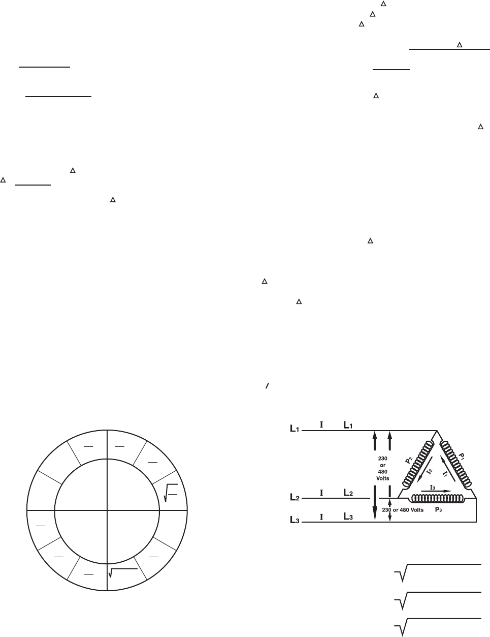
35
Table 30.
Conversion Factors (constant)
Water
500 = 8.33 lbs./gal. x 60 min, – (Converts GPM to lbs./hr.)
Air
4.5 = 60 min
13.35 Cu. Ft./lb. – (Converts CFM to lbs./hr.)
1.08 = 4.5 x 0.241 BTU/lb./ºF. – (lbs./hr. x Sp. Ht. of Air)
0.68 = 4.5 x 1054.3 BTU/lb.
7000 gr/lb. – (4.5 combined with heat
of vaporization of water
at 70ºF. and grains per
pound of water)
Water Heating, Cooling & Heat Reclaim Coils, Water Chillers,
Condensers, etc.
Q = 500 x GPM x T = BTU/hr.
T = Q
500 x GPM
For brines, Q = 500 x GPM x T x (Sp. Ht. x Sp. Gr. of Brine)
Air Coils
Q Sensible = 1.08 x CFM x T = BTU/hr.
Q Latent = 0.68 x CFM x SH = BTU/hr.
Q Total = 4.5 x CFM x H = BTU/hr.
lb./hr. Condensate = 4.5 x CFM x SH Grains
7000 grains/lb
SHR Sensible Heat Ratio = Q Sensible
Q Total
Heat Transmission
Q Total = U x A Surface x T = BTU/hr.
Product
Sensible Heat in BTU/hr. = lbs/hr. x Sp. Ht. x T
Latent Heat in BTU/hr. = lbs/hr. x Lt. Ht. in Btu/lb.
Heat of Resp. in BTU/hr . = lbs x Heat or Respiration
in BTU/lb./hr.
All conversion factors used in standard calculations must be
corrected for other than standard properties
Properties of Water at 39.2 ºF.
Density of Water = 62.4 lbs./Cu. Ft.
Specic Heat of Water = 1 BTU/lb./ºF.
Latent Heat of = 970 BTU/lb. at 212ºF. & Atm.
Vaporization = 1054.3 BTU/lb. at 70ºF.
Specic Heat of Ice = 0.5 BTU/lb./ºF.
Latent Heat of Fusion = 144 BTU/lb.
1 Gallon of Water = 8.33 lbs.
1 Pound of Water = 7000 Grains
Nomenclature
Q = Heat Flow in BTU/hr.
T = Temperature in ºF. ( T = temp. di.)
A = Area in Sq. Ft.
U = Coef. of Heat Transfer in BTU/hr./Sq.Ft./ºF.
H = Total heat of air at wet bulb temp. BTU/lb.
H = Enthalpy dierence between entering & leaving air
SH = Specic humidity in grains of moisture/lb. of dry air
( SH = Specic humidity dierence for entering
and leaving air)
CFM = Cu. Ft./min.
GPM = Gal/min.
W I
R E
I2 X R
E X I
I X R
E2
W
E
R
E
R W
E
W
I
W
I2
E
I
W
R
W X R
Table 31.
Single Phase Loads
Ohm’s Law for direct current
W = Watts
I = Current (Amperes)
E = Electromotive Force (Volts)
R = Resistance (Ohms)
To obtain any values in the center circle, for Direct or Alternating
Current, perform the operation indicated in one segment of the
adjacent outer circle.
3 Phase Delta Loads
3 0 Balanced Loads = P1 + P2 + P3
Total Line Current = Total Power (Balanced Load)
If the phase are unbalanced, each of the phase will dier from
the others:
FORMULAE:
I
L1 =
I
2 +
I
2 + (
I
1 X
I
2 )
3 1
I
L2 =
I
2 +
I
2 + (
I
2 X
I
3 )
2 3
I
L3 =
I
2 +
I
2 + (
I
1 X
I
3 )
3 1
36
Table 32.
English Conversion Factors & Data
Table 33.
English to Metric Conversion Factors
To Convert Measurements
From To Multiply By
Cubic Feet Cubic Inches 1728
Cubic Inches Cubic Feet 0.00058
Cubic Feet Gallons 7.48
Gallons Cubic Feet 0.1337
Cubic Inches Gallons 0.00433
Gallons Cubic Inches 231
Barrels Gallons 42
Gallons Barrels 0.0238
Imperial Gallons U.S. Gallons 1.2009
U.S. Gallons Imperial Gallons 0.8326
Feet Inches 12
Inches Feet 0.0833
Square Feet Square Inches 144
Square Inches Square Feet 0.00695
Short Tons Pounds 2000
Liters U.S. Gallons 0.2642
To Convert Pressure (at 32ºF.)
From To Multiply By
Inches of Water Pounds per Sq. Inch 0.03612
Pounds per Sq. Inch Inches of Water 27.866
Feet of Water Pounds of Sq. Inch 0.4334
Pounds per Sq. Inch Feet of Water 2.307
Inches of Mercury Pounds per Sq. Inch 0.4912
Pounds per Sq. Inch Inches of Mercury 2.036
Atmospheres Pounds per Sq. Inch 14.696
Pounds per Sq. Inch Atmosphere 0.06804
To Convert Power
From To Multiply By
Horsepower Metric Horsepower 1.014
Horsepower Ft./Pounds per Min. 33000
Horsepower Kilowatts 0.746
Kilowatts Horsepower 1.3404
British Thermal Units Foot/Pounds 778.177
Foot/Pounds British Thermal Units 0.001285
British Thermal Units Horsepower Hours 0.0003927
Horsepower Hours British Thermal Units 2544.1
British Thermal Units Kilowatt Hours 0.0002928
Kilowatt British Thermal Units 3415
Watt Hour British Thermal Units 3.415
Volume – Weight Conversions Wt. lbs.
1 Cubic Foot of Water 62.4*
1 Cubic Inch of Water 0.0361*
1 Gallon of Water 8.33*
1 Cubic Foot of Air 0.075†
1 Cubic inch of Steel 0.284
1 Cubic Foot of Brick (Building) 112-120
1 Cubic Foot of Concrete 120-140
1 Cubic Foot of Earth 70-120
* at 32ºF.
† at 70ºF. and 29.92” Hg.
To Convert Measurements
From To Multiply By
Cubic Feet Cubic Centimeters 28317
Cubic Inches Cubic Centimeters 16.387
Cubic Feet Liters 28.32
Gallons Liters 3.7854
Cubic Inches Liters 0.0164
Gallons Cubic Centimeters 3785.4
Barrels Cubic Meters 1.0551
Imperial Gallons Cubic Meters 0.0045461
U.S. Gallons Cubic Meters 0.0037854
Feet Meters 0.3048
Inches Meters 0.0254
Square Feet Square Meters 0.0929
Square Inches Square Centimeters 6.452
Ton (Short, 2000lb.) Kilograms 907.2
Liter Cubic Meter 0.0001
Pounds Kilograms 0.45359
To Convert Pressure (at 32ºF.)
From To Multiply By
Inches of Water Newton/Sq. Meter 249.082
Pounds per Sq. Inch Newton/Sq. Meter 6894.8
Feet of Water Newton/Sq. Meter 2988.98
Pounds per Sq. Inch Kilograms/Sq. Cent. 0.07031
Inches of Mercury Newton/Sq. Meter 3386.4
Pounds per Sq. Inch Dyne/Sq. Cent. 68948
Atmospheres Newton/Sq. Meter 101325
Pascal Newton/Sq. Meter 1
To Convert Power
From To Multiply By
Horsepower Watt 745.7
British Thermal Units Joule 1054.35
Foot – Pounds Joule 1.3558
British Thermal Units Calorie 252.0
British Thermal Units Watt Second 1054.35
Watt – Second Joule 1
Calorie Joule 4.184
Watt Hours Joule 3600
Kilocalorie/Minute Watt 69.73
Ton (Refrigerated) Watt 3516.8
BTU/Hour Watt 0.29288
BTU/In/Hr. Ft.2 ºF. Watt/Meter ºK. 0.14413
BTU/Hr. at 10ºF. T.D. Kcal/Hr. at 6ºC. T.D. 0.252
BTU/Hr. at 15ºF. T.D. Kcal/Hr. at 8ºC. T.D. 0.252
Volume – Weight Conversions Wt. Kilograms
1 Cubic Foot of Water 28.3*
1 Cubic Inch of Water 0.0164*
1 Gallon of Water 3.788*
1 Cubic Foot of Air 0.034†
1 Cubic inch of Steel 0.1288
1 Cubic Foot of Brick (Building) 51-54
1 Cubic Foot of Concrete 54-64
1 Cubic Foot of Earth 32-54
* at 32ºF.
† at 70ºF. and 29.92” Hg.
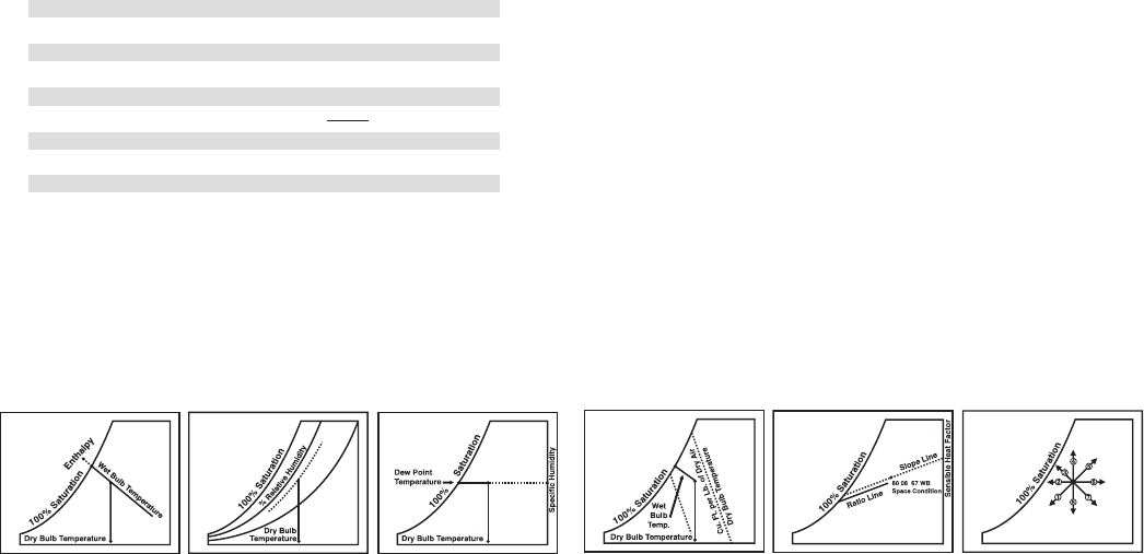
37
78.1 SR/lb dry air
7000
Use of the Psychrometric Chart
From two known properties of air, its condition can be located on
the Psychrometric chart and all remaining properties can then be
found by reading the appropriate scale.
Figure 1 Illustrates a condition plotted at the intersection of its
dry bulb and wet bulb temperatures. The dry bulb temperature
is represented on the chart by the vertical lines with its scale
across the bottom. The wet bulb temperature is read along
the saturation line and is represented on the chart by the solid
diagonal lines. Enthalpy at a saturation, for a given wet bulb
temperature is read from the diagonal scale at the left using the
diagonal lines extending from the saturation line.
Figure 2 Illustrates a condition plotted at the intersection of its
dry bulb temperature and relative humidity. Relative humidity is
represented on the chart by the curved lines which are marked in
percent relative humidity.
Figure 3 Illustrates a condition plotted at the intersection
of its dry bulb and dew point temperatures. The dew point
temperature is read along the saturation line at the intersection
of the Horizontal Humidity line. The value of the specic humidity
is read from the scales at the right in either pounds or grains of
moisture per pound of dry air by selecting the appropriate scale.
Figure 4 Illustrates the determination of specic volume from the
chart. Specic volume is represented by the broken diagonal lines
marked in cubic feet per pound of dry air. Intermediate points are
read by interpolation between the lines.
Figure 5 Illustrates the use of sensible heat factor to determine
the air conditions required to satisfy a specied space
temperature and load conditions. The sensible heat factor is the
ratio of internal sensible heat to internal total heat load of the
space being conditioned. A straight line from the sensible heat
factor scale through the circled point of the chart to the slope line
from the space condition point to the saturation line. Air supplied
to the space at any temperature condition located on the ratio
line (and in the proper volume) will satisfy the room load.
Example — Using the point which is circled on the Psychrometric
Chart, the following values are obtained:
Dry Bulb Temperature 80.0ºF.
Wet Bulb Temperature 67.0ºF.
Dew Point Temperature 60.3ºF.
Relative Humidity 51.1%
Specic Humidity
A) 0.01115 lbs./lb. dry air =
B) 78.1 grains/lb. dry air
Enthalpy at saturation 31.62 BTU/lb. dry air
Specic Volume 13.83 Cu. Ft./lb. dry air
Figure 6 … *Air Conditioned Process
1. Cooling and Dehumidication — A decrease in both dry bulb
and specic humidity represented by a line sloping
downward and to the left. Total heat content (both sensible
and latent heat) is decreased.
2. Sensible Cooling — A decrease in dry bulb and sensible heat
content represented by a horizontal line directed to the loft
along the constant specic humidity line. Specic humidity
and dew point remain constant.
3. Evaporating Cooling — (Air passed through spray water or
wetted surface at wet bulb temperature) – A decrease in dry
bulb (reduced sensible heat content) and an increase in dew
point and specic humidity (increased latent heat content)
represented by a line sloping upward and to the left following
a constant wet bulb line – no change in total heat content.
4. Humidication — An increase in the specic humidity as a
result of moisture added, represented by a line directed
upward.
5. Heating and Humidication — An increase in both sensible
heat and specic humidity, represented by a line sloping
upward and to the right.
6. Sensible Heating — An increase in dry bulb and sensible heat
content, represented by a horizontal line directed to the right
along the constant specic humidity line, Specic humidity
and dew point remain constant.
7. Chemical Drying — (Air passed through a chemical drying
agent) – A decrease in dew point and specic humidity,
represented by a line sloping downward and to the right.
8. Dehumidication — a decrease in the specic humidity as a
result of removing moisture, represented by a line directed
downward.
Denitions
Dry Bulb Temperature — The temperature indicated by a
thermometer, not aected by the water vapor content air.
Wet Bulb Temperature — The temperature of air indicated by
a wet bulb thermometer; the temperature at which water, by
evaporating into air, can bring the air to saturation adiabatically at
the same temperature.
Dew Point Temperature — The temperature to which water vapor
in air must be reduced to produce condensation of the moisture
contained therein.
Relative Humidity — The ratio of actual vapor pressure in the
air to the vapor pressure of saturated air at the same dry bulb
temperature.
Specic Humidity (Moisture Content of Humidity Ratio) — The
weight of water vapor per pound of dry air.
Sensible Heat — Heat which when added or subtracted from
the air changes only its temperature with no eect on specic
humidity.
Latent Heat — Heat which eects a change of state without
aecting temperature, as in evaporating or condensing moisture.
Enthalpy (Total Heat) — The sum of sensible and latent heat. In
the chart, enthalpy represents units of total heat content above
an arbitrary base in terms of BTU per pound of dry air.
Specic Volume — Volume per unit of weight, the reciprocal of
density, in terms of cubic feet per pound of dry air.
Sensible Heat Factor — The ratio of internal sensible heat to
internal total heat load.
Ratio Line — The line extending from the space condition to the
saturation line at a slope determined by the sensible heat factor.
Fig 1 —
Dry Bulb and Wet Bulb
Fig 2 —
Dry Bulb and Relative
Humidity
Fig 3 —
Dry Bulb and Dew Point
Fig 4 —
Specic Volume
Fig 5 —
Sensible Heat Factor
Fig 6 —
Air Conditioning Process
* (See Above)
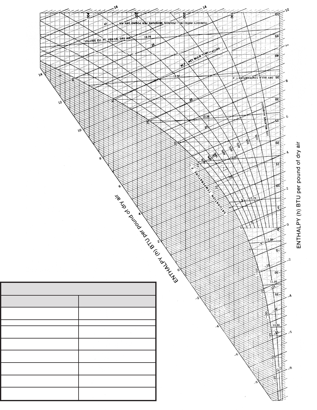
38
Appendix — Charts
Low Temperature Psychrometric Chart (-40 to 50ºF.)
Standard Atmospheric Pressure of 29.921 in HG
Atmospheric Pressure
at other altitude
Altitude Pressure
Ft. in HG
-1000 31.02
-500 30.47
0 29.92
500 29.38
1000 28.86
2000 27.82
3000 26.83
4000 25.84
5000 24.90
6000 23.98
7000 23.09
8000 22.22
9000 21.39
10000 20.58
15000 16.89
Courtesy of ASHRAE — Reproduced by permission.
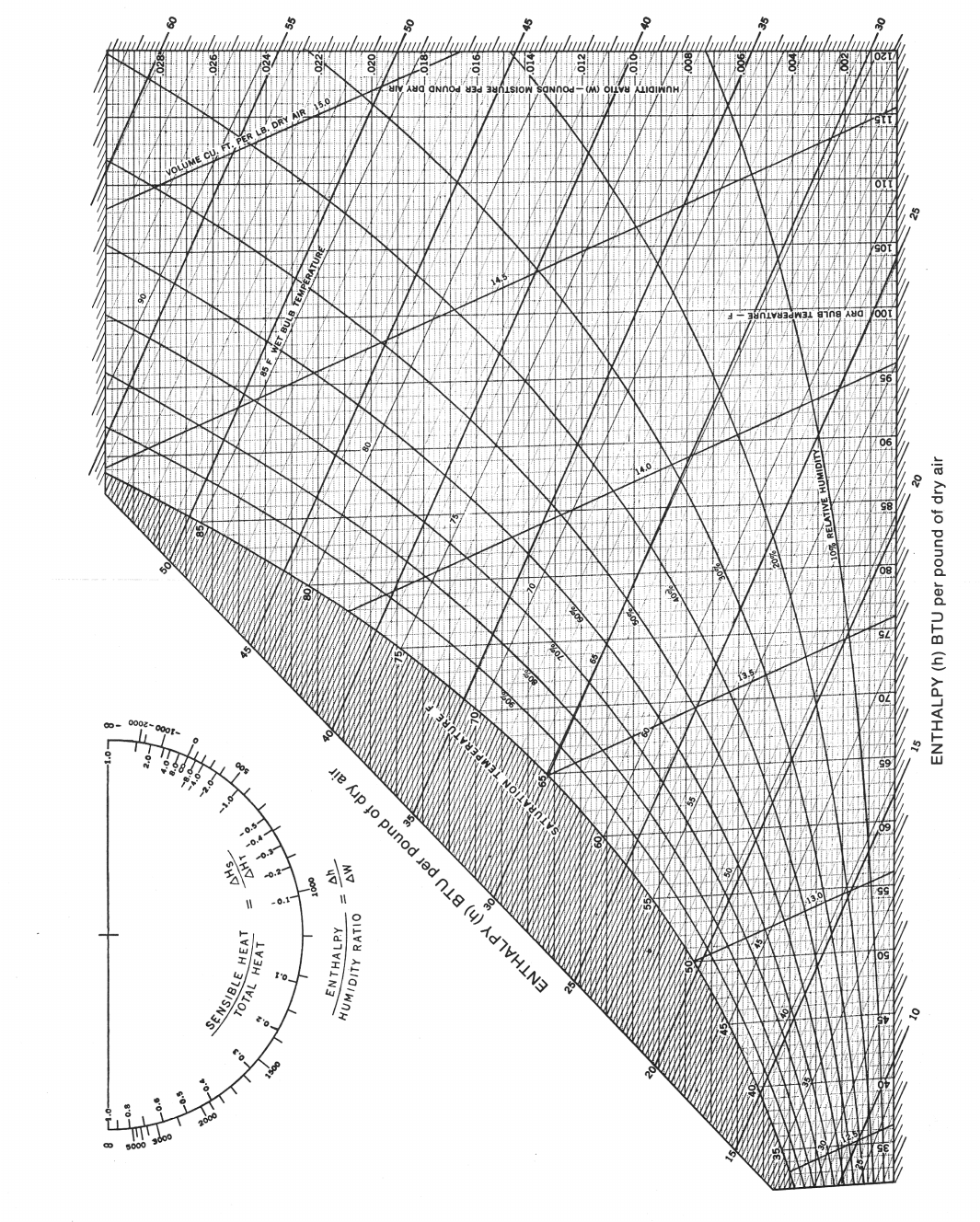
39
Appendix — Charts
Medium Temperature Psychrometric Chart (32 to 130ºF.)
Standard Atmospheric Pressure of 29.921 in HG
Courtesy of ASHRAE — Reproduced by permission.
40
Glossary of Refrigeration Terms
1. Accumulator - a shell placed in suction line for separating
liquid refrigerant entrained in suction gas.
2. Air Changes - the amount of air leakage is sometimes
computed by assuming a certain number of air changers
per hour for each room, the number of changes assumed
being dependent upon the type, use and location of the
room.
3. Air Cooler, Forced Circulation - a factory-made encased
assembly of elements by which heat is transferred from
air to evaporating refrigerant.
4. Ambient Air - generally speaking, the air surrounding an
object. In a domestic or commercial refrigerating system
having an air-cooled condenser, the temperature of the
air entering the condenser.
5. Back Pressure - loose terminology for suction pressure of
refrigeration vapor in a system.
6. British Thermal Unit (BTU) - heat required to produce a
temperature rise of 1 degree Fahrenheit in 1 lb. of water.
The mean BTU is 1/180 of the energy required to heat
water from 32ºF. to 212ºF.
7. Change of Air - introduction of new, cleansed or
recirculated air to conditioned space, measured by the
number of complete changes per unit time.
8. Chill - to apply refrigeration moderately, as to meats,
without freezing.
9. Chilling Room - room where animal carcasses are cooled
after dressing prior to cold storage.
10. Comfort Air Conditioning - the simultaneous control of
all, or at least the rst three, of the following factors
aecting the physical and chemical conditions of the
atmosphere within a structure for the purpose of human
comfort; temperature, humidity, motion, distribution,
dust, bacteria, odors, toxic gasses and ionization, most of
which aect in greater or lesser degree human health or
comfort.
11. Comfort Cooling - refrigeration for comfort as opposed
to refrigeration for storage or manufacture.
12. Defrosting Cycle - a refrigeration cycle which permits
cooling unit to defrost during o period.
13. Dehumidication - the conservation of water vapor from
air by cooling below the dew point or removal of water
vapor from air by chemical or physical methods.
14. Dehydration - the removal of water vapor from air by the
use of absorbing materials. (2) The removal of water from
stored goods.
15. Dew Point - temperature at which condensation starts
if moist air is cooled at constant pressure with no loss or
gain of moisture during the cooling process.
16. Dierential (of a control) - the dierence between cut-in
and cut-out temperature or pressure.
17. Dry Bulb Temperature - temperature measured by
ordinary thermometer (term used only to distinguish
from wet-bulb temperature).
18. Duct - a conduit or tube used for conveying air or other
gas.
19. Evaporator - the part of a system in which refrigerant
liquid is vaporizing to produce refrigerant.
20. External Equalizer - in a thermostatic expansion valve,
a tube connection from the chamber containing the
evaporation pressure-actuated element of the valve to
the outlet or the evaporator coil. A device to compensate
for excessive pressure drop throughout the coil.
21. Flash Gas - the gas resulting from the instantaneous
evaporation
of refrigerant in a pressure-reducing device to cool the
refrigerant to the evaporations temperature obtained at
the reduces pressure.
22. Flooded System - system in which only part of the
refrigerant passing over the heat transfer surface is
evaporated, and the portion not evaporated is separated
from the vapor and recirculated. In commercial systems,
one controlled by a oat valve.
23. Frost Back - the ooding of liquid from an evaporator
into the suction line accompanied by frost formation in
suction line in most cases.
24. Head Pressure - operating pressure measured in
thedischarge line at the outlet from the compressor.
25. Heat Exchanger - apparatus in which heat is exchanged
from one uid to another through a partition.
26. Heat, Latent - heat characterized by change of state of
the substance concerned, for a given pressure and always
at a constant temperature for a pure substance, i.e., heat
of vaporization or fusion.
27. High Side - parts of refrigerating system under condenser
pressure.
28. Inltration - air owing inward as through a wall, leak,
etc.
29. Liquid Line - the tube or pipe carrying the refrigerant
liquid from the condenser or receiver of a refrigerating
system to a pressure-reducing device.
30. Low Side - parts of a refrigerating system under
evaporator pressure.
31. Pressure Drop - loss in pressure, as from one end of a
refrigerant line to the other, due to friction, etc.
32. Refrigerating System - a combination of inter-connected
refrigerant-containing parts in which a refrigerant is
circulated for the purpose of extracting heat.
33. Respiration - production of CO2 and the heat by ripening
of perishables in storage.
34. Return Air - air returned from conditioned or refrigerated
space.
35. Sensible Heat - heat which is associated with a change in
temperature; specic heat x change of temperature; in
contrast to a heat interchange in which a change of state
(latent heat) occurs.
36. Specic Heat - energy per unit of mass required to
produce one degree rise in temperature, usually BTU per
lb. degree F. numerically equal to cal. per gram degree C.
37. Standard Air - air weighing 0.075 lb. per cu. ft. which is
closely air at 68ºF. dry bulb and 50% relative humidity
at barometric pressure of 29.92 in. of mercury of
approximately dry air at 70ºF. at the same pressure.
38. Suction line - the tube or pipe which carries the
refrigerant vapor from the evaporator to the compressor
inlet.
39. Superheat - temperature of vapor above its saturation
temperature at that pressure.
40. Temperature, Wet-Bulb - equilibrium temperature of
water evaporating into air when the latent heat of
vaporization is supplied by the sensible heat of air.
41. Thermal Valve - a valve controlled by a thermally
responsive element, for example, a thermostatic
expansion valve which is usually responsive to suction or
evaporator temperature.
42. Throw - the distance air will carry, measured along the
axis of an air stream from the supply opening to the
position, is the stream at which air motion reduces to 50
fpm.
43. Ton of Refrigeration - a rate of heat interchange of
12,000 BTU per hour; 200 BTU per min.
44. Unit Cooler - adapted from unit heater to cover any
cooling element of condensed physical proportions and
large surface generally equipped with fan.

41
6x6x8 36 4750 6389 4488 6037 4583 6505 4929 7041 5274 7577
6x8x8 48 5417 7274 5119 6974 5225 7407 5630 8028 6034 8648
6x10x8 60 6055 8100 5722 7655 5806 8213 6265 8911 6725 9609
8x8x8 64 6188 8291 5848 7835 5934 8410 6405 9127 6876 9844
8x10x8 80 6954 9269 6572 8759 6631 9363 7165 10169 7699 10974
8x12x8 96 7669 10174 7247 9614 7273 10234 7867 11123 8461 12011
8x14x8 112 8366 11045 7905 10437 7922 11092 8575 12059 9227 13026
8x16x8 128 9051 11888 8553 11234 8528 11890 9237 12933 9946 13976
8x18x8 144 9748 12732 9212 12032 9169 12732 9936 13852 10702 14972
8x20x8 160 10419 13548 9846 12803 9755 13490 10576 14682 11397 15874
8x22x8 176 11540 14807 10905 13992 10817 14715 11692 15977 12567 17239
8x24x8 192 12224 15622 11522 14763 11386 15439 12314 16769 13242 18099
8x26x8 208 12874 16398 12166 15496 11976 16176 12955 17573 13935 18970
8x28x8 224 13519 17163 12775 16219 12530 16873 13562 18336 14594 19799
8x30x8 240 14187 17947 13407 16960 13108 17587 14191 19115 15274 20642
8x32x8 256 14824 18694 14009 17666 13653 18264 14786 19855 15920 21446
10x10x8 100 7789 10339 7361 9770 7386 10401 7990 11304 8594 12208
10x12x8 120 8626 11385 8152 10759 8138 11405 8809 12401 9481 13397
10x14x8 140 9439 12384 8920 11703 8887 12405 9626 13493 10365 14581
10x16x8 160 10250 13379 9686 12643 9577 13311 10379 14484 11182 15658
10x18x8 180 11049 14349 10441 13560 10279 14216 11144 15472 12009 16728
10x20x8 200 11838 15299 11187 14458 10942 15070 11868 16405 12794 17741
10x24x8 240 13391 17180 12654 16207 12751 17231 13796 18721 14842 20211
10x28x8 280 14891 18922 14072 17881 14043 18844 15205 20482 16367 22120
12x12x8 144 10038 13021 9486 12305 8991 12553 9739 13655 10486 14756
12x14x8 168 10956 14155 10353 13376 10235 14052 11055 15251 11875 16450
12x16x8 192 11886 15284 11232 14443 11029 15082 11919 16375 12810 17667
12x18x8 216 12775 16359 12072 15459 11807 16080 12767 17464 13726 18847
12x20x8 240 13681 17440 12928 16481 12573 17052 13599 18524 14626 19995
12x22x8 264 14549 18474 13749 17458 13299 17974 14392 19541 15485 21088
14x14x8 196 11993 15423 11333 14575 11126 15216 12024 16521 12923 17826
14x16x8 224 13013 16656 12297 15740 11995 16338 12971 17745 13946 19152
14x20x8 280 15011 19042 14185 17795 13687 18487 14811 20088 15935 21688
14x24x8 336 16969 21347 16036 21073 15330 20539 16598 22324 17866 24110
16x16x8 256 14148 18019 13370 17028 12939 17550 13998 19067 15056 20583
16x20x8 320 16349 20631 15450 19496 14777 19873 15996 21598 17215 23323
16x24x8 374 18506 23157 17488 21883 16563 22093 17938 24017 19313 25941
18x18x8 324 16476 20782 15570 19639 14864 19989 16090 21724 17317 23460
18x20x8 360 18128 22644 17131 21398 16305 21678 17617 23523 18930 25369
18x24x8 432 20484 25389 19357 23993 18260 24090 19739 26149 21219 28208
20x20x8 400 19470 24145 18340 22817 17386 23019 18790 24982 20194 16945
20x24x8 480 21988 27132 20779 25640 19453 25566 21036 27755 22619 29945
20x28x8 560 24963 30480 23590 28804 21963 28514 23721 30922 25479 33330
20x32x8 640 27480 33340 25969 31506 23954 30909 25884 33529 27813 36149
20x36x8 720 29946 36127 28299 34140 25919 33251 28017 36077 30115 38903
20x40x8 800 32420 38904 30637 36764 27888 35575 30153 38603 32518 41631
24x40x8 960 38694 45735 36565 46878 34681 43023 37368 46538 39939 49937
28x40x8 1120 43183 50733 40808 48970 38123 47062 41095 50921 43950 54664
32x40x8 1280 48550 56318 45880 55056 42894 51900 46146 56580 49282 60656
36x40x8 1440 54344 62804 51355 61626 46254 56259 49872 60781 53194 65186
40x40x8 1600 58738 67611 55507 66608 49583 60073 53385 64916 57070 69642
BTUH Load
+35 Room +30 Room 0 Room -10 room -20 Room
Floor Usage Usage Usage Usage Usage
Dimension Sq. Ft. Avg. Heavy Avg. Heavy Avg. Heavy Avg. Heavy Avg. Heavy
Quick Selection Guide
*Heavy usage is defined as two times the average air change. Average air
changes determined by ASHRAE based on box size for 24 hour period.
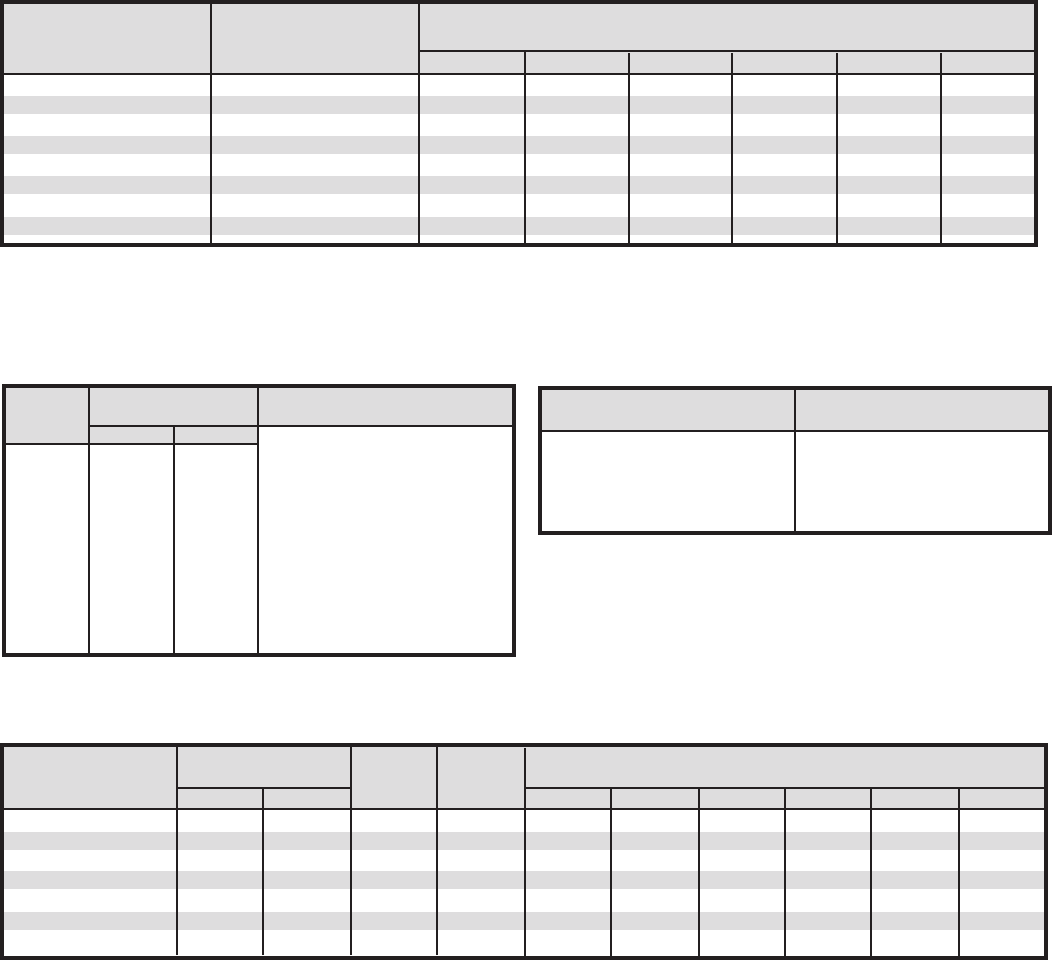
42
Tips for Quick Selection Guide
Walk- In Cooler Box Load Parameter
1. 95ºF. ambient air temperature surrounding box.
2. 4” Styrene (R=16.7, K=0.24) walls/ceilling, 6” concrete slab oor.
3. Average product load with 5ºF. pull down in 24 hours.
4. BTUH load based on 16-18 hour compressor run time for 35ºF.
box (timer recommended) +20 hours for 30ºF. box.
5. See Table C for adjustment to box load for glass doors.
6. For 80ºF. ambient temp. surrounding box, deduct 12%.
7. For 4” Urethane walls+ceiling, 6” concrete slab oor deduct 12%.
8. For 10’ ceiling height add 10%.
9. For additional BTUH load for product cooling see Table A.
Walk-In Freezer Box Load Parameters
1. 95ºF. ambient air temperature surrounding box.
2. 4” Urethane (R=25, K=0.16) walls, ceiling + oor.
3. Average product load with 10 degree pull down in 24 hours.
4. BTUH load based on 18 hour compressor run time.
5. See Table C for adjustment to box load for glass doors.
6. For 80ºF. ambient air temp. surrounding box, deduct 12%.
7. For 20 hour compressor run time (light frost load) in lieu of 18
hour run time, deduct 11%
8. For 10’ ceiling height add 10%
9. For additional BTUH load for product freezing, refer to Table D
Specic Heat 10 Degree Pull down BTUH Load for Indicated
Product Above lbs of Product per 24 Hours
Freezing 500 1000 1500 2000 3000 5000
Beef 0.72 240 480 720 960 1440 2400
Pork 0.53 177 353 530 706 1060 1767
Veal & Lamb 0.76 253 506 760 1012 1520 2533
Poultry 0.79 263 526 790 1053 1580 2633
Seafood 0.80 267 533 800 1066 1600 2667
Vegetables 0.92 307 613 920 1226 1840 3067
Bakery Food 0.74 247 494 740 988 1480 2467
Beer 1 333 666 1000 1333 2000 3333
Table A
Product Cooling Loads for Walk-In Coolers
(24 hour pull down/18 hour compressor operation) 24% safety factor added to loads to allow for service.
For product pull down greater than 10 degrees, divide pull down
temperature by 10. Multiply this number by the BTUH shown on
Table A, then add to Box Load
Floor Approx. 65% R.H.
SQ FT Room Temp.
55ºF. 50ºF.
100 93 105
200 88 99
300 85 95
400 81 90
500 78 87
600 75 85
700 72 81
800 69 78
900 67 75
1000 65 73
1200 62 69
Room Loads based on continuous
operation and includes allowance
for average number of personnel,
processing equipment, etc., with
glass panel in one wall and walls
and ceiling insulated with 3” of
styrene with box located in air
conditioned area. Evaporator
should be low outlet velocity type
to avoid drafts and should be
selected for continuous operation
and not less than 30ºF. evap. temp.
Table B
Meat Cutting/Prep Room Load (BTU/HR/SQ FT of oor area)
Table C
Glass Door Loads
Box BTU per
Temperature Door
+35 1060
+30 960
0 1730
-10 1730
-20 1730
* Adjusted for 16-18 hour run time. Multiply number of doors
times door load above and add to box load.
Spec. Heat Latent Freezer
Product BTU/lb/Deg. F. Heat Temp. -10ºF. Freezer Temperature BTUH for Indicated lbs. Prod/Day
32 + 32 - BTU/lb. (F) 100 300 750 1000 1500 3000
Beef 0.72 0.40 95 29 790 2370 5925 7900 11850 23700
Pork 0.53 0.32 60 28 523 1571 3926 5235 7853 15710
Veal & Lamb 0.76 0.45 100 28 841 2524 6311 8414 12621 25240
Poultry 0.79 0.42 106 27 878 2636 6590 8787 13181 26360
Seafood 0.80 0.43 110 28 906 2719 6797 9063 13595 27190
Vegetables 0.92 0.47 130 30 1053 3159 7898 10530 15795 31590
Bakery Foods 0.74 0.34 53 20 520 1560 3900 5200 7800 15600
Table D
Product Freezing Loads for Walk-In Freezers
Freezing loads based on product entering at 40ºF. maximum.
For a specic pull down time, the product load BTU/hr. may be
adjusted by multiplying the above loads by 24 and dividing by
the specic pull down time in hours. To adjust for 0ºF. freezer
temperature, multiply the above loads by 0.97, and for -20ºF.
freezer, multiply by 1.04.
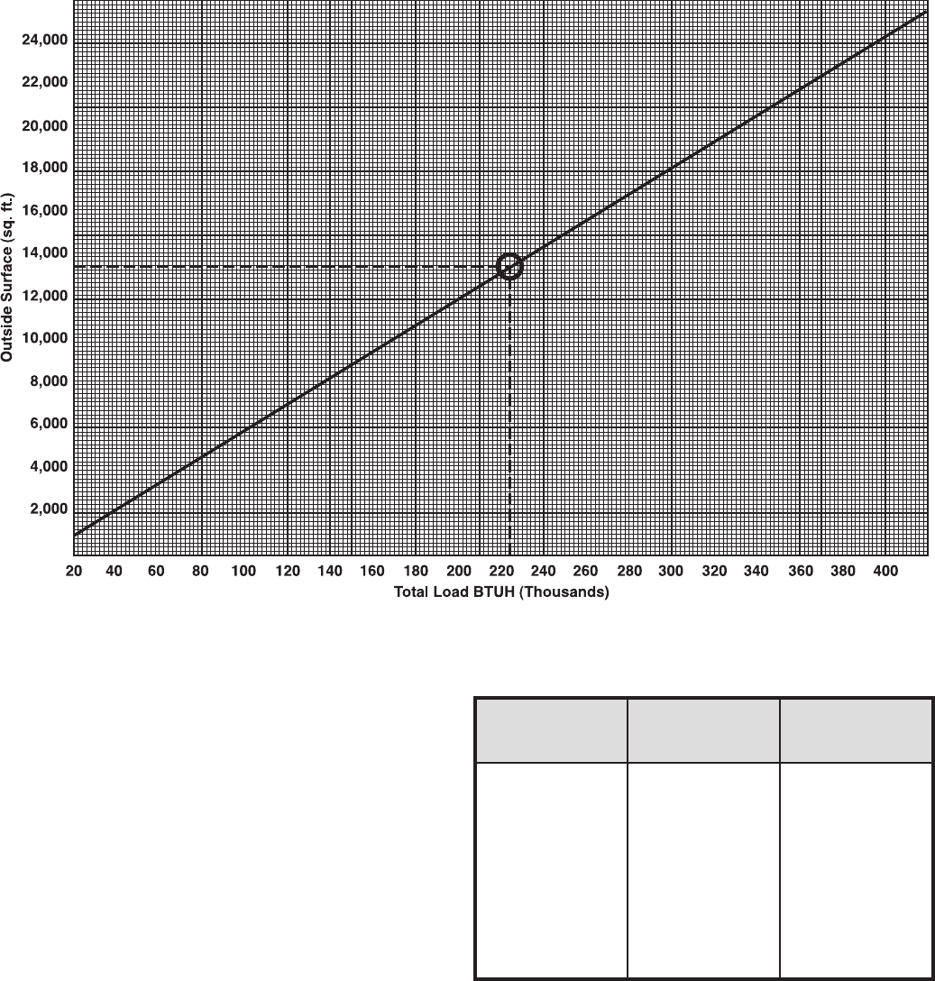
43
Rapid Load Calculator for Large Coolers and Freezers
Design Conditions: 95ºF. ambient; heavy
service; 16-hr. compressor running time;
average number of lights, motors, and
people; product load gured according
to accompanying table; product trac
calculated at 30 degree temperature
reduction for coolers, 10 degree
temperature reduction for freezers.
Note: This calculator will work equally well
for coolers and freezers, providing the room
is insulated as indicated below:
35ºF. cooler- 3” polystyrene or equivalent
30ºF. cooler- 4” polystyrene or equivalent
0ºF. cooler- 5” polystyrene or equivalent
-10ºF. cooler- 5 1/2” polystyrene or equivalent
-20ºF. cooler- 6” polystyrene or equivalent
Example: 100 x 40 x 20’ zero ºF. freezer.
Outside surface totals 13,600 sq. ft. Find
13,600 sq. ft. outside surface line at left
of graph. Follow it across to the straight
line curve. Then drop down to total load
line at bottom of graph. Total load for this
example is 224,000 BTUH. Select equipment
accordingly.
Material originated by Hugo Smith, consulting editor, Air
Conditioning and Refrigeration Business. Reprinted by permission
from the April 1968 issue of Air Conditioning and Refrigeration
Business. Copyright by Industrial Publishing Co., Division of Pittway
Corporation.
Average Daily Average Daily
Volume- Product Loads (lbs.) Product Loads (lbs.)
Cu. Ft. for Coolers for Freezers
500 - 3,000 6,200 - 8,000 1,600 - 2,000
3,000 - 4,600 8,000 - 11,000 2,000 - 2,500
4,600 - 8,100 11,000 - 17,000 2,500 - 4,000
8,100 - 12,800 17,000 - 26,000 4,000 - 6,200
12,800 - 16,000 26,000 - 33,000 6,200 - 7,500
16,000 - 20,000 33,000 - 40,000 7,500 - 9,500
20,000 - 28,000 40,000 - 56,000 9,500 - 13,000
28,000 - 40,000 56,000 - 66,000 13,000 - 17,000
40,000 - 60,000 66,000 - 110,000 17,000 - 25,000
60,000 - 80,000 110,000 - 150,000 25,000 - 34,000
80,000 - up 150,000 - up 34,000 - up

44
®
CLIMA
TE
C
ONTROL
Commercial Refrigeration Parts
™
Since product improvement is a continuing eort, we reserve the right to make changes in
specications without notice.
®
CLIMATE
C
ONTROL
Commercial Refrigeration Parts
The name behind the brands you trust.™
Heatcraft Refrigeration Products LLC
2175 West Park Place Blvd • Stone Mountain, GA 30087
Phone: 800.321.1881• Fax: 770.465.5990 • www.heatcraftrpd.com
H-ENGM 0408
