HeathCo 60WRC14TX Remote Control User Manual 598 1108 rev00
HeathCo LLC Remote Control 598 1108 rev00
HeathCo >
Users Manual
DRAFT COPY
FEATURES
•Products are UL/cUL and/or FCC/IC tested and approved.
•Operational range of up to 100 feet.
This manual applies to the following products:
•Wall Switch Transmitter
•Wall Switch Receiver
Remote Controlled Products
This manual includes operating instructions for a variety of remote controlled products. All products work on the same principle and use the same
channel setting information. Please read all instructional information and note any specific information pertaining to your particular product.
WARNINGS:
•FOR USE ONLY with 120 volt incandescent or halogen bulbs.
•DO NOT USE with fluorescent bulbs, appliances, power supplies, low voltage lighting, or any other electrical devices.
© 2002 DESA International 598-1135-00
ENGLISH
WALL SWITCH TRANSMITTER
Installation
1. Select mounting location for wall switch transmitter.
Note:
Transmitter should be located within 100 feet
(30 m) of receiver.
2. Before mounting, place transmitter in selected lo-
cation and verify operation (see
Operation
).
Note:
If transmitter does not operate correctly, see
Troubleshooting Guide
).
3. Mount transmitter to wall using two #8 x 1 3/4" wood screws
(provided). Transmitter should be mounted approximately 4
feet from the floor and in the vertical position. Use drywall
anchors (provided) if not mounting to wall stud.
Operation
1. Verify power disconnect switch on wall switch receiver is in
ON position. Wall switch transmitter will not operate lights if
power disconnect switch is in OFF position.
2. Push the ON (top) button and release. The light should turn
on full bright.
3. Push the OFF (bottom) button and release. The light should
turn off.
4. Push the DIM button and release. The light should turn on at
50% brightness (or last setting).
5. Continue to press the DIM button until the desired dim level
is reached.
Note:
DIM setting remembers last setting used.
To recall last DIM setting, push and release the DIM button.
Note:
The DIM setting defaults to 50% in the event of a power
failure.
Important: Wait 1 to 2 seconds after you press a transmitter
button before you press it again to allow the transmission to be
completed.
Note:
If light does not turn on or intermittently turns on and off when
transmitter buttons are pushed, see
Troubleshooting Guide
.
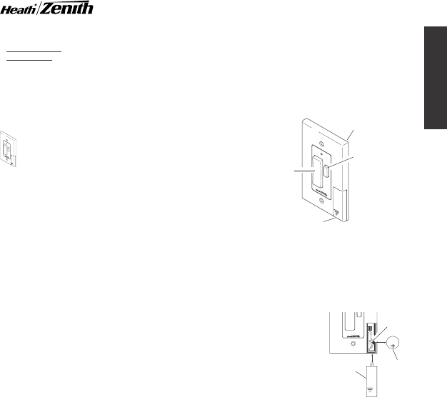
DIM
Wall Switch Transmitter
Wall Switch
ON/OFF
Button
DIM
Button
Access Door
DIM
Battery Replacement
The wall switch transmitter requires a type CR2032, 3-volt
lithium battery to operate. The transmitter is shipped with the
battery installed. With typical use, the battery will last approxi-
mately one year. Remove battery when transmitter will not be
used for an extended period of time.
1. Place thumb on access
door and slide down to
open.
2. Carefully bend locking
tab outward. Battery will
pop up.
3. Remove battery from
socket.
4. Install replacement bat-
tery in socket plus (+)
side up (see illustra-
tion). Press down on
battery until locking tab
snaps into place.
5. Reinstall access door
by sliding it upward until it locks in place.
1 2 3 4
ON
DIM
2032
3
V
L
i
t
h
i
u
m
B
a
t
t
e
r
y
CR2032
Lithium
Battery
Battery
Locking
Tab
Access
Door
Removing Access Door and
Battery
2
598-1135-00
DRAFT COPY
Features and Ratings:
•Rated for 120VAC/60Hz supply voltage.
•Up to 300 Watt maximum incandescent load.
•Not for use with Compact Fluorescent bulbs.
•Up to 100 feet (30 m) typical transmission range.
•Fits standard single gang junction box.
Important: This product can not be used if more than one switch
is being used to control the light.
Important: Never install two wall switch receivers within 3 feet
(0.9 m) of each other. This may reduce the operating range.
WALL SWITCH RECEIVER
Installation
1. Locate light switch to be replaced by wall switch receiver.
2. Turn off the power to the light switch circuit before you
proceed. Do this at your circuit breaker or fuse box.
3. Remove the existing wall plate and switch. Disconnect the
two power wires and the ground wire.
Note:
If there are more than two power wires attached to the
switch, consult an electrician about installation. In addition,
some local building codes may require installation by a qualified
electrician.
4. Connect one of the black power wires from receiver to one
of the power wires you removed from the old switch. Use one
of the supplied wire connectors to secure the wires (see
illustration).
5. Connect the second black power wire from receiver to the
other power wire you removed from the old switch. Use one
of the supplied wire connectors to secure the wires (see
illustration).
6. Connect the green ground wire from receiver to the ground
wire removed from old switch. Use one of the supplied wire
connectors to secure the wires (see illustration).
7. Check wire connections to make sure they are secure and
that no bare wires are exposed.
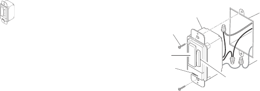
8. Position the wall switch receiver in the junction box with the
DIM button located to the right. Use the two wall switch screws
(long) supplied to mount the receiver to the wall box (see
illustration). Push excess wiring into wall box while you do this.
You may need to bend the wires to fit inside the box. Mount
wall plate on wall switch receiver with screws (short) provided.
Installing Wall Switch Receiver
9. Turn on the power to the light switch circuit. Do this at your
circuit breaker or fuse box.
Wall Switch
Screw
Ground Wire
(Bare or
Green)
Junction
Box
Wall Switch
ON/OFF
Button
DIM Button
Power
Disconnect
Switch
Operation
1. Verify the power disconnect switch is in the ON (right side)
position.
2. Push the ON (top) button and release. The light should turn
on full bright.
Note:
If you are controlling a lamp, make sure
it is connected to the switched outlet and the lamp is
switched on.
3. Push the OFF (bottom) button and release. The light should
turn off.
4. Push either the top or bottom of DIM button and release. The
light should turn on at 50% brightness (or last setting).
5. Push and release top of DIM button to increase brightness.
Push and release bottom of DIM button to decrease bright-
ness.
Note:
There are 5 DIM settings ranging from 15% to
90% brightness.
6. Set desired DIM level.
Note:
DIM setting remembers last
setting used. To recall last DIM setting, push and release
either the top or bottom of DIM button.
Note:
The DIM setting defaults to 50% in the event of a power
failure.
Bulb Replacement
Move the power disconnect switch to the OFF (left side) position.
Replace bulb(s).
Caution: Do not exceed the maximum load limits listed above.
3
598-1135-00
ENGLISH
DRAFT COPY
CHANNEL SETTINGS
Note:
Most installations will not require you to change any of
the dip switches on your wireless product or remote control.
Note:
If purchasing more than one remote control system,
select different operating channels unless interaction is
desired between the systems.
These remote control products communicate by using channels
that can be changed by sliding dip switches into the ON or OFF
[on some switches the numbers 1 (ON) and/or 0 (OFF) are used]
position on both the transmitter and receiver unit(s). The channel
is factory set; however, there are 3 switches (8 selectable
channels) that allow you to expand your system and prevent
outside interference. Other remote controlled unit(s) may cause
interference and the system may not function properly. Follow
the instructions below for setting a new channel.
1. Open the cases and locate dip switches on both the transmit-
ter and receiver unit(s).
2. Dip switches 1 through 3 are used for setting the channel
(Remote Control Only - position 4 is not used and should
remain in OFF position).
3. To change the channel, slide dip switches to ON or OFF as
needed. It is recommended to only change one dip switch at
a time and then check to see if system is functioning properly.
IMPORTANT:
Dip switches in positions 1 through 3 must be
in the exact same configuration on both the transmitter and
receiver unit(s) for this system to function properly.
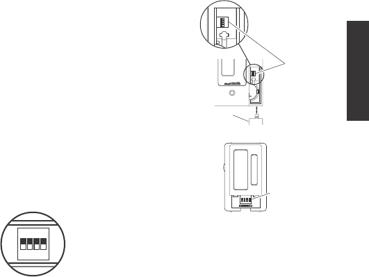
Dip Switches - Shown
in the OFF Position
(Factory Default)
ON
1 2 3 4
Dip Switches
1 2 3 4
ON
2032
3
V
L
i
t
h
i
u
m
B
a
t
t
e
r
y
DIM
ON
DIP SWITCH LOCATIONS
Wall Switch Transmitter
Wall Switch Receiver
Dip
Switches
Dip
Switches
Access Door
1 2 3 4
ON
h
i
u
m
B

4
598-1135-00
DRAFT COPY
TROUBLESHOOTING GUIDE
POSSIBLE CAUSE
1. Circuit breaker or fuse is turned off.
2. Switch on device is turned off.
3. Interrupted by another device.
4. Does not respond immediately after
installation.
5. Device is defective.
6. Signals from transmitter are being
blocked, or transmitter is out of range.
7. Weak battery in the transmitter.
8. Dip switches on transmitter and re-
ceiver units do not match.
1. Same as 6, 7, and 8 above.
1. Short term power line failure.
2. Another transmitter on the same
channel.
SYMPTOM
Device does not come on.
Device does not turn off.
Device comes on randomly.
SOLUTION
1. Verify circuit breaker or fuse is
turned on.
2. Verify switched device is turned on.
3. Change channels on transmitter and
receiver units.
4. Wait for 90 second initialization
period (remote motion sensor).
5. Test using different device.
6. Check for metal objects that could
block the signal, or reposition the
transmitter.
7. Check battery charge and replace if
necessary.
8. Verify dip switch settings on trans-
mitter and receiver units are set the
same.
1. Same as 6, 7, and 8 above.
1. Short term power line failure.
2. Change channels on transmitter and
receiver units.

5
598-1135-00
ENGLISH
DRAFT COPY
REGULATORY INFORMATION
This device complies with Part 15 of the FCC Rules and RSS-210 of Industry Canada. Operation is subject to the following two
conditions: (1) this device may not cause harmful interference, and (2) this device must accept any interference received, including
interference that may cause undesired operation.
The term "IC:" before the radio certification number only signifies that Industry Canada technical specifications were met.
The user is cautioned that changes or modifications not expressly approved by the party responsible for regulatory compliance could
void the user’s authority to operate the equipment.
YOUR HEATH®/ZENITH TWO YEAR LIMITED WARRANTY
This is a "Limited Warranty" which gives you specific legal rights. You may also have other rights which vary from state to
state or province to province.
For a period of two years from the date of purchase, any malfunction caused by factory defective parts or workmanship will
be corrected at no charge to you. Light bulbs and Batteries not covered. To obtain a refund or a replacement, return the
product to the place of purchase.
Not Covered - Repair service, adjustment and calibration due to misuse, abuse or negligence, light bulbs and other expend-
able items are not covered by this warranty. Unauthorized service or modification of the product or of any furnished compo-
nent will void this warranty in its entirety. This warranty does not include reimbursement for inconvenience, installation, setup
time, loss of use, or unauthorized service.
This warranty covers only Heath®/Zenith assembled products and is not extended to other equipment and components that
a customer uses in conjunction with our products.
THIS WARRANTY IS EXPRESSLY IN LIEU OF ALL OTHER WARRANTIES, EXPRESS OR IMPLIED, INCLUDING ANY
WARRANTY, REPRESENTATION OR CONDITION OF MERCHANT ABILITY OR THAT THE PRODUCTS ARE FIT FOR
ANY PARTICULAR PURPOSE OR USE, AND SPECIFICALLY IN LIEU OF ALL SPECIAL, INDIRECT, INCIDENTAL, OR
CONSEQUENTIAL DAMAGES.
REPAIR OR REPLACEMENT SHALL BE THE SOLE REMEDY OF THE CUSTOMER AND THERE SHALL BE NO LIABIL-
ITY ON THE PART OF DESA FOR ANY SPECIAL, INDIRECT, INCIDENTAL, OR CONSEQUENTIAL DAMAGES, INCLUD-
ING BUT NOT LIMITED TO ANY LOSS OF BUSINESS OR PROFITS, WHETHER OR NOT FORESEEABLE. Some states
or provinces do not allow the exclusion or limitation of incidental or consequential damages, so the above limitation or
exclusion may not apply to you. Retain receipt for warranty claims.
NO SERVICE PARTS AVAILABLE FOR THESE PRODUCTS
TECHNICAL SERVICE
(Do Not Send Products)
If you experience a problem, follow this guide. You may also want to visit our Web site at: www.desatech.com. If the problem persists,
call* for assistance at 1-800-858-8501, 7:30 AM to 4:30 PM CST (M-F). You may also write* to:
DESA International, Inc.
P.O. Box 90004, Bowling Green, KY 42102-9004
* If contacting Technical Service, please have the following information available: Model Number, Date of Purchase, and Place of Purchase.
DESA International reserves the right to discontinue products and to change specifications at any time without incurring any obligation
to incorporate new features in products previously sold.