HeathCo 60WRC30TX 6030 Motion Sensor User Manual 598 1108 rev00
HeathCo LLC 6030 Motion Sensor 598 1108 rev00
UserManual.wiki
>
HeathCo
>
60WRC30TX User Manual
Users Manual
Navigation menu
Upload a User Manual
Namespaces
Wiki Guide
HTML
PDF
Info
Views
User Manual
Discussion / Help
Navigation
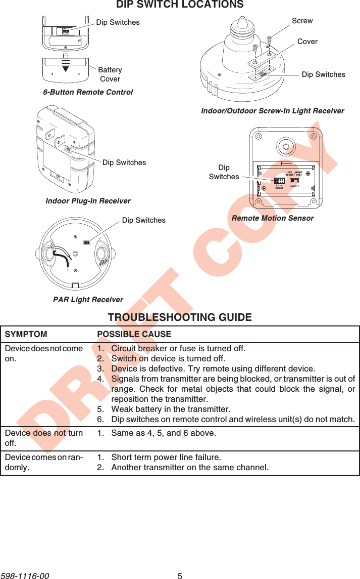
![4598-1116-00DRAFT COPYMaximumCoverage AngleAim Sensor Down forShort Coverage Aim Sensor Higher forLong CoverageMaximum RangeAdjusting Motion Sensor CoverageCoverage AreaMotionMost SensitiveMotion Sensor SensitivityLeast SensitiveMotionSensor SensorThe detector is most sensitive to motion acrossits field of view.4. Set ON-TIME Control. Determine the amountof time you want the connected device tostay on after motion is detected (1 or 5minutes). Slide the ON-TIME control to thecorresponding setting.IMPORTANT: Avoid Aiming Control At:•Objects that change temperature rapidly, suchas heating vents and air conditioners. Theseheat sources could cause false triggering.•Areas where pets or traffic may trigger thecontrol.•Nearby large, light colored objects reflectinglight may trigger the shut-off feature. Do notpoint other lights at the sensor.70 ft.(21 m)8 ft.(2.4 m)180°CHANNEL SETTINGSNote: Most installations will not require youto change any of the dip switches on yourwireless product or remote control.Note: If purchasing more than one remotecontrol system, select different operatingchannels unless interaction is desired be-tween the systems.These remote control products communicate byusing channels that can be changed by slidingdip switches into the ON or OFF [on someswitches the numbers 1 (ON) and/or 0 (OFF) areused] position on both the transmitter and re-ceiver unit(s). The channel is factory set; how-ever, there are 3 switches (8 selectable chan-nels) that allow you to expand your system andprevent outside interference. Other remote con-trolled unit(s) may cause interference and thesystem may not function properly. Follow theinstructions below for setting a new channel.1. Open the cases and locate dip switches onboth the transmitter and receiver unit(s).2. Dip switches 1 through 3 are used for settingthe channel (Remote Control Only - position4 is not used and should remain in OFFposition).3. To change the channel, slide dip switches toON or OFF as needed. It is recommended toonly change one dip switch at a time and thencheck to see if system is functioning properly.IMPORTANT: Dip switches in positions 1through 3 must be in the exact same con-figuration on both the transmitter and re-ceiver unit(s) for this system to functionproperly.Dip Switches - Shown in theOFF Position (FactoryDefault)ON1 2 3 4Dip SwitchesRemote Sensor Controls - Bottom View51TESTON-TIME(MINUTES)RANGEMAX MINON-TIMEControl SensitivityControlLEDIndicator](https://usermanual.wiki/HeathCo/60WRC30TX/User-Guide-226659-Page-4.png)