HeathCo 60WRC30TX 6030 Motion Sensor User Manual 598 1108 rev00
HeathCo LLC 6030 Motion Sensor 598 1108 rev00
HeathCo >
Users Manual
DRAFT COPY
© 2002 DESA International 598-1116-00
FEATURES
•Products are UL/cUL and/or FCC/IC tested
and approved.
•Operational range of up to 100 feet.
Remote Controlled Products
This manual applies to the following products:
•6-Button Remote Control
•Indoor Plug-In Receiver
•PAR Light Receiver
•Indoor/Outdoor Screw-In Light Receiver
•Remote Motion Sensor
This manual includes operating instructions for a variety of remote controlled products. All products
work on the same principle and use the same channel setting information. Please read all
instructional information and note any specific information pertaining to your particular product.
Note:
One remote control is able to
independently operate two receiver units
set on the same channel. If more than
two receiver units, operating indepen-
dently, are desired, additional remote
controls will need to be purchased.
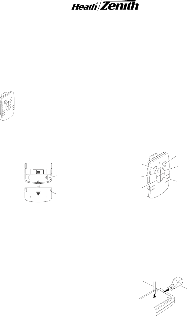
1. Install alkaline 12-Volt remote battery (A23
type). Remove cover from back of transmit-
ter. Using outline of battery chamber as a
guide, align battery with chamber and insert
battery. Slide cover onto transmitter.
ON
1 2 3 4
Battery
Chamber
(Type A23)
Battery
Cover
Rear View of Remote Control
6-BUTTON REMOTE CONTROL
2. Remote Control Functions. The three but-
tons on the left side of the remote will oper-
ate one or more receiver units with matching
addresses. The three buttons on the right
side of the remote will operate a second set
of one or more receiver units.
•Channel 1/2 ON: Turns on any receiver unit set
to the same channel as this remote control.
•Channel 1/2 OFF: Turns off any receiver unit
set to the same channel as this remote control.
•Channel 1/2 DIM: Activates the DIM feature
for any receiver unit set to the same channel
as this remote control.
Note:
To independently operate a second re-
ceiver unit using a single remote control, make
sure the 4th dip switch on each receiver is set to
different settings.
•Channel 1 - Slide dip switch 4 to the ON
position on each receiver to be operated by
these buttons.
•Channel 2 - Slide dip switch 4 to the OFF
position on each receiver to be operated by
these buttons.
Channel 1 DIM
Channel 1 ON
Channel 1 OFF
Channel 2 DIM
Channel 2 ON
Channel 2 OFF
Function Controls
Flat-Head
Screwdriver Optional
Visor Clip
Removing Visor Clip - Rear View
Optional Car Visor Clip (Included)
The remote control includes an optional car visor
clip for added convenience that may be installed.
1. To attach car visor clip to remote control (if
desired) push it into slot on rear of remote
unit until it snaps into place.
2. To remove car visor clip, insert a small, flat-
head screwdriver into slot on back of remote.
Gently push down on portion of visor clip
inside slot with screwdriver while pulling clip
out of remote from top.
2
598-1116-00
DRAFT COPY
PAR LIGHT
RECEIVER
Features and
Ratings:
•Up to 300 Watt incandescent load (up to 150
Watt per lampholder).
•Minimal wiring required.
RECEIVER INFORMATION
All receivers have the following features and
ratings:
•Rated for 120VAC/60Hz supply voltage.
•Light can be dimmed when used with remote
control (OFF, Low, Med, Hi, Full On).
•Remembers last selected dim setting.
•Not for use with Compact Fluorescent bulbs.
INDOOR PLUG-IN
RECEIVER
Features and Ratings:
•Up to 2.5 Amps resistive load.
•Up to 300-Watt incandescent load.
•No wiring required.
1. Plug in indoor receiver.
2. Plug in light you wish to control.
Caution: Do not exceed the maximum load
limits listed above.
3. Check operation. Either activate remote
motion sensor or toggle ON/OFF switches
on remote control to check operation.
4. Using Remote By-Pass Switch. These re-
ceivers are equipped with a remote by-pass
switch. This switch allows the user to select
between ON and RECEIVER modes. ON
mode allows the plugged in light to be oper-
ated manually. RECEIVER mode allows the
light to be operated by remote control or
remote motion sensor.
5. Adjust audio alert volume (if applicable).
Some models are equipped with an audible
alarm which sounds each time the receiver
is activated. The alarm volume is adjusted
by the thumbwheel on the side of the re-
ceiver unit.
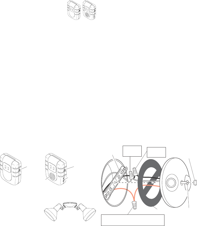
Control Locations
Remote
By-Pass
Switch
Remote
By-Pass
Switch
Alarm Volume
Control
Speaker
White to
White Black to
Black
Gasket
Mounting
Strap
Mounting
Bolt
Rubber
Plug
Junction box ground wire to
green ground screw on fixture.
Wiring PAR Light Receiver
Turn power off at the fuse or circuit breaker.
1. Remove the existing light fixture.
2. Install the mounting strap as shown using
two screws that fit your junction box.
Note:
The plastic hanger can be used to hold
the fixture while wiring. Thread the small end
of the plastic hanger through the hole in the
center of the cover plate. Insert the small end
into one of the slots on the mounting strap.
3. Route the wires from the light receiver
through the large gasket holes.
4. Twist the junction box wires and fixture
wires together as shown. Secure with UL
approved wire connectors.
5. Align the cover plate and cover plate gas-
ket. Secure with mounting bolt.
6. Push the rubber plug firmly into place.
7. If a wet location junction box was not used,
caulk the wall plate mounting surface with
silicone weather sealant.
8. Adjust the lamp holders by loosening the lock
nuts.
Note:
Do not rotate the lamp holders
more than 180° from the factory setting.
Caution: To avoid water damage and elec-
trical shock, keep lamp holders 30° below
horizontal.
9. Screw incandescent bulb up to rated watt-
age into module. When screwing in the
lamps, do not overtighten.
Caution: Do not exceed the maximum load
limits listed above.
10. Check operation. Either activate remote
motion sensor or toggle ON/OFF switches
on remote control to check operation.
3
598-1116-00
DRAFT COPY
INDOOR/OUTDOOR
SCREW-IN LIGHT
RECEIVER
Features and Ratings:
•Up to 150 Watt incandescent load.
•No wiring required.
1. Screw module into light socket.
2. Screw incandescent bulb up to rated watt-
age into module.
Caution: Do not exceed the maximum load
limits listed above.
3. Check operation. Either activate remote
motion sensor or toggle ON/OFF switches
on remote control to check operation.
REMOTE MOTION
SENSOR
Features:
•No wiring required.
•Up to 70 feet sensing range, 180° Coverage.
•Adjustable sensitivity.
•Day/Night or Night only operation.
•Test mode.
•Uses 2 AA batteries.
•Wall or eave mount.
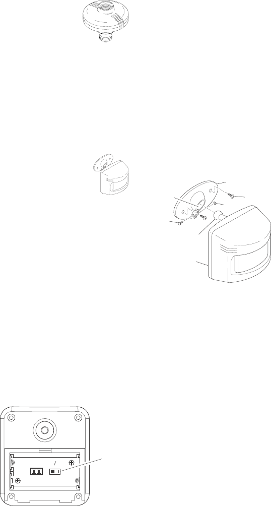
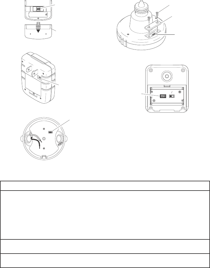
Select Night or 24 Hour Mode
This sensor is able to detect motion day and night
or night only. To set the detection mode, remove
rear panel by sliding the panel down. Remove
batteries if necessary. Slide the DETECT switch
to either the DAY/NIGHT or NIGHT ONLY posi-
tion. Replace rear panel by reversing the above
instructions.
Installing Batteries
Before mounting sensor, remove rear panel by
sliding the panel down. Install 2 AA batteries
according to polarity markings inside the battery
compartment. Replace rear panel by reversing the
above instructions.
Battery Compartment - Rear View
DETECT
CODES
1234
DAY
NIGHT
NIGHT
ONLY
Detect
Control
Installing Remote Sensor
1. Install sensor mounting bracket where mo-
tion detection is desired. Attach sensor
mounting bracket to a sturdy object (i.e.
tree, post, house, etc.) using two screws
provided. Make sure unit has an unob-
structed view.
2. Install remote sensor to mounting bracket.
Using a Philips-head screwdriver, loosen the
clamp screw on the mounting bracket. Insert
swivel ball mount on sensor into mounting
bracket socket (
Note:
You should hear a
snap). Aim sensor toward area where detec-
tion is desired. Tighten clamp screw.
IMPORTANT:
The sensor must be mounted with
the bottom cover facing down in order to maintain
water tightness.
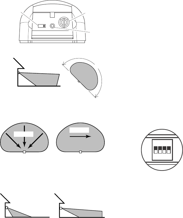
Check Operation and Adjustment
The RANGE control and ON-TIME control are
located on the bottom of the sensor. Using your
fingernails or a small, flat-head screwdriver, gen-
tly pry the cover until it opens.
1. Check Operation. Set the ON-TIME control
to TEST mode. Walk in front of sensor unit.
The LED indicator light located on the bot-
tom of the sensor should flash when motion
is detected.
2. Adjust Sensor. Turn the RANGE control to
the mid position and ON-TIME control to the
TEST position. Walk through coverage area
noting where you are when the LED begins
to flash. Loosen the clamp screw and move
the sensor to change the coverage area.
Tighten clamp screw when finished. Do not
overtighten clamp screw.
3. Adjust Range Control. To increase sensitiv-
ity, turn the RANGE control toward MAX. To
decrease sensitivity, turn the RANGE con-
trol toward MIN.
Note:
If the RANGE is set
too high, false triggering may result in some
environments.
Installing Remote Sensor
Mounting Bracket
Clamp
Screw
Nut
Sensor
Mounting Screw
Swivel Ball Mount
Mounting
Bracket
Socket
4
598-1116-00
DRAFT COPY
Maximum
Coverage Angle
Aim Sensor Down for
Short Coverage Aim Sensor Higher for
Long Coverage
Maximum Range
Adjusting Motion Sensor Coverage
Coverage Area
Motion
Most Sensitive
Motion Sensor Sensitivity
Least Sensitive
Motion
Sensor Sensor
The detector is most sensitive to motion across
its field of view.
4. Set ON-TIME Control. Determine the amount
of time you want the connected device to
stay on after motion is detected (1 or 5
minutes). Slide the ON-TIME control to the
corresponding setting.
IMPORTANT:
Avoid Aiming Control At:
•Objects that change temperature rapidly, such
as heating vents and air conditioners. These
heat sources could cause false triggering.
•Areas where pets or traffic may trigger the
control.
•Nearby large, light colored objects reflecting
light may trigger the shut-off feature. Do not
point other lights at the sensor.
70 ft.
(21 m)
8 ft.
(2.4 m)
180°
CHANNEL SETTINGS
Note:
Most installations will not require you
to change any of the dip switches on your
wireless product or remote control.
Note:
If purchasing more than one remote
control system, select different operating
channels unless interaction is desired be-
tween the systems.
These remote control products communicate by
using channels that can be changed by sliding
dip switches into the ON or OFF [on some
switches the numbers 1 (ON) and/or 0 (OFF) are
used] position on both the transmitter and re-
ceiver unit(s). The channel is factory set; how-
ever, there are 3 switches (8 selectable chan-
nels) that allow you to expand your system and
prevent outside interference. Other remote con-
trolled unit(s) may cause interference and the
system may not function properly. Follow the
instructions below for setting a new channel.
1. Open the cases and locate dip switches on
both the transmitter and receiver unit(s).
2. Dip switches 1 through 3 are used for setting
the channel (Remote Control Only - position
4 is not used and should remain in OFF
position).
3. To change the channel, slide dip switches to
ON or OFF as needed. It is recommended to
only change one dip switch at a time and then
check to see if system is functioning properly.
IMPORTANT:
Dip switches in positions 1
through 3 must be in the exact same con-
figuration on both the transmitter and re-
ceiver unit(s) for this system to function
properly.
Dip Switches - Shown in the
OFF Position (Factory
Default)
ON
1 2 3 4
Dip Switches
Remote Sensor Controls - Bottom View
51TEST
ON-TIME
(MINUTES)
RANGE
MAX MIN
ON-TIME
Control Sensitivity
Control
LED
Indicator
5
598-1116-00
DRAFT COPY
ON
1 2 3 4
Dip Switches
Battery
Cover
6-Button Remote Control
PAR Light Receiver
Dip Switches
ON
1 2 3 4
Dip Switches
Indoor Plug-In Receiver
DIP SWITCH LOCATIONS
1 2 3 4
Dip Switches
Screw
Cover
Indoor/Outdoor Screw-In Light Receiver
Remote Motion Sensor
DETECT
CODES
1234
DAY
NIGHT
NIGHT
ONLY
Dip
Switches
TROUBLESHOOTING GUIDE
POSSIBLE CAUSE
1. Circuit breaker or fuse is turned off.
2. Switch on device is turned off.
3. Device is defective. Try remote using different device.
4. Signals from transmitter are being blocked, or transmitter is out of
range. Check for metal objects that could block the signal, or
reposition the transmitter.
5. Weak battery in the transmitter.
6. Dip switches on remote control and wireless unit(s) do not match.
1. Same as 4, 5, and 6 above.
1. Short term power line failure.
2. Another transmitter on the same channel.
SYMPTOM
Device does not come
on.
Device does not turn
off.
Device comes on ran-
domly.

6
598-1116-00
DRAFT COPY
REGULATORY INFORMATION
This device complies with Part 15 of the FCC Rules and RSS-210 of Industry Canada. Operation is subject
to the following two conditions: (1) this device may not cause harmful interference, and (2) this device must
accept any interference received, including interference that may cause undesired operation.
The user is cautioned that changes or modifications not expressly approved by the party responsible
for regulatory compliance could void the user’s authority to operate the equipment.
YOUR HEATH®/ZENITH TWO YEAR LIMITED WARRANTY
This is a "Limited Warranty" which gives you specific legal rights. You may also have other rights which
vary from state to state or province to province.
For a period of two years from the date of purchase, any malfunction caused by factory defective parts
or workmanship will be corrected at no charge to you. Light bulbs and Batteries not covered. To
obtain a refund or a replacement, return the product to the place of purchase.
Not Covered - Repair service, adjustment and calibration due to misuse, abuse or negligence, light bulbs
and other expendable items are not covered by this warranty. Unauthorized service or modification of the
product or of any furnished component will void this warranty in its entirety. This warranty does not include
reimbursement for inconvenience, installation, setup time, loss of use, or unauthorized service.
This warranty covers only Heath®/Zenith assembled products and is not extended to other equipment
and components that a customer uses in conjunction with our products.
THIS WARRANTY IS EXPRESSLY IN LIEU OF ALL OTHER WARRANTIES, EXPRESS OR IMPLIED,
INCLUDING ANY WARRANTY, REPRESENTATION OR CONDITION OF MERCHANT ABILITY OR
THAT THE PRODUCTS ARE FIT FOR ANY PARTICULAR PURPOSE OR USE, AND SPECIFICALLY
IN LIEU OF ALL SPECIAL, INDIRECT, INCIDENTAL, OR CONSEQUENTIAL DAMAGES.
REPAIR OR REPLACEMENT SHALL BE THE SOLE REMEDY OF THE CUSTOMER AND THERE
SHALL BE NO LIABILITY ON THE PART OF DESA FOR ANY SPECIAL, INDIRECT, INCIDENTAL, OR
CONSEQUENTIAL DAMAGES, INCLUDING BUT NOT LIMITED TO ANY LOSS OF BUSINESS OR
PROFITS, WHETHER OR NOT FORESEEABLE. Some states or provinces do not allow the exclusion
or limitation of incidental or consequential damages, so the above limitation or exclusion may not apply
to you. Retain receipt for warranty claims.
NO SERVICE PARTS AVAILABLE FOR THESE PRODUCTS
TECHNICAL SERVICE
(Do Not Send Products)
If you experience a problem, follow this guide. You may also want to visit our Web site at:
www.desatech.com. If the problem persists, call* for assistance at 1-800-858-8501, 7:30 AM to 4:30
PM Central Time weekdays. You may also write* to:
DESA International, Inc.
P.O. Box 90004, Bowling Green, KY 42102-9004
* If contacting Technical Service, please have the following information available: Model Number,
Date of Purchase, and Place of Purchase.
Heath®/Zenith reserves the right to discontinue products and to change specifications at any time
without incurring any obligation to incorporate new features in products previously sold.