Heatiator GB4336 4003 085H GB4942 User Manual To The D1ec77c5 F68c 4ece 973b 443d3ce10907
User Manual: Heatiator GB4336 to the manual
Open the PDF directly: View PDF ![]() .
.
Page Count: 52
Heatilator • GB4336/GB4992 • 4003-085 Rev H • 04/06 1
Owner’s Manual
Installation and Operation
Models:
GB4336, GB4336L,
GB4336I, GB4336IL,
GB4942, GB4942L,
GB4942I, GB4942IL
B-Vent Gas Appliance
Installation and service of this appliance should be performed
by qualified personnel. Hearth & Home Technologies
suggests NFI certifi ed or factory-trained
professionals, or technicians supervised
by an NFI certifi ed professional.
If the information in these instruc-
tions is not followed exactly, a
fi re may result causing property
damage, personal injury, or death.
• Do not store or use gasoline or other fl am-
mable vapors and liquids in the vicinity of
this or any other appliance.
• What to do if you smell gas:
- Do not try to light any appliance.
- Do not touch any electrical switch. Do not
use any phone in your building.
- Immediately call your gas supplier from
a neighbor’s phone. Follow the gas
supplier’s instructions.
- If you cannot reach your gas supplier, call
the fi re department.
• Installation and service must be performed
by a qualifi ed installer, service agency, or
the gas supplier.
WARNING
HOT! DO NOT TOUCH.
SEVERE BURNS MAY RESULT.
CLOTHING IGNITION MAY RESULT.
WARNING
• Keep children away.
• CAREFULLY SUPERVISE children in same room as
appliance.
• Alert children and adults to hazards of high
temperatures.
• Do NOT operate with protective barriers removed or
door open.
• Keep clothing, furniture, draperies and other
combustibles away.
Glass and other surfaces are hot during
operation and cool down.
This appliance may be installed as an OEM installation
in manufactured home (USA only) or mobile home and
must be installed in accordance with the manufacturer’s
instructions and the manufactured home construction and
safety standard, Title 24 CFR, Part 3280 or Standard for
Installation in Mobile Homes, CAN/CSA Z240MH.
This appliance is only for use with the type(s) of gas indicated
on the rating plate.
In the Commonwealth of Massachusetts:
• installation must be performed by a licensed plumber or gas fi tter.
• a CO detector shall be installed in the room where the appliance is
installed.
DO NOT DISCARD THIS MANUAL
CAUTION
• Important operating and
maintenance instructions
included.
• Leave this manual with
party responsible for
use and operation.
• Read, understand and follow
these instructions for safe
installation and operation.
DO NOT
DISCARD
2 Heatilator • GB4336/GB4992 • 4003-085 Rev H • 04/06
Read this manual before installing or operating this appliance.
Please retain this owner’s manual for future reference.
Congratulations on selecting a Heatilator gas appliance—an
elegant and clean alternative to wood burning appliances.
The Heatilator gas appliance you have selected is designed
to provide the utmost in safety, reliability, and effi ciency.
As the owner of a new appliance, you’ll want to read and
carefully follow all of the instructions contained in this owner’s
manual. Pay special attention to all cautions and warnings.
This owner’s manual should be retained for future reference.
We suggest you keep it with your other important documents
and product manuals.
The information contained in this owner’s manual, unless
noted otherwise, applies to all models and gas control
systems.
Your new Heatilator gas appliance will give you years of
durable use and trouble-free enjoyment. Welcome to the
Heatilator family of appliance products!
Homeowner Reference Information
Model Name: Date purchased/installed:
Serial Number: Location on appliance:
Dealership purchased from: Dealer phone:
Notes:
We recommend that you record the following pertinent
information about your appliance:
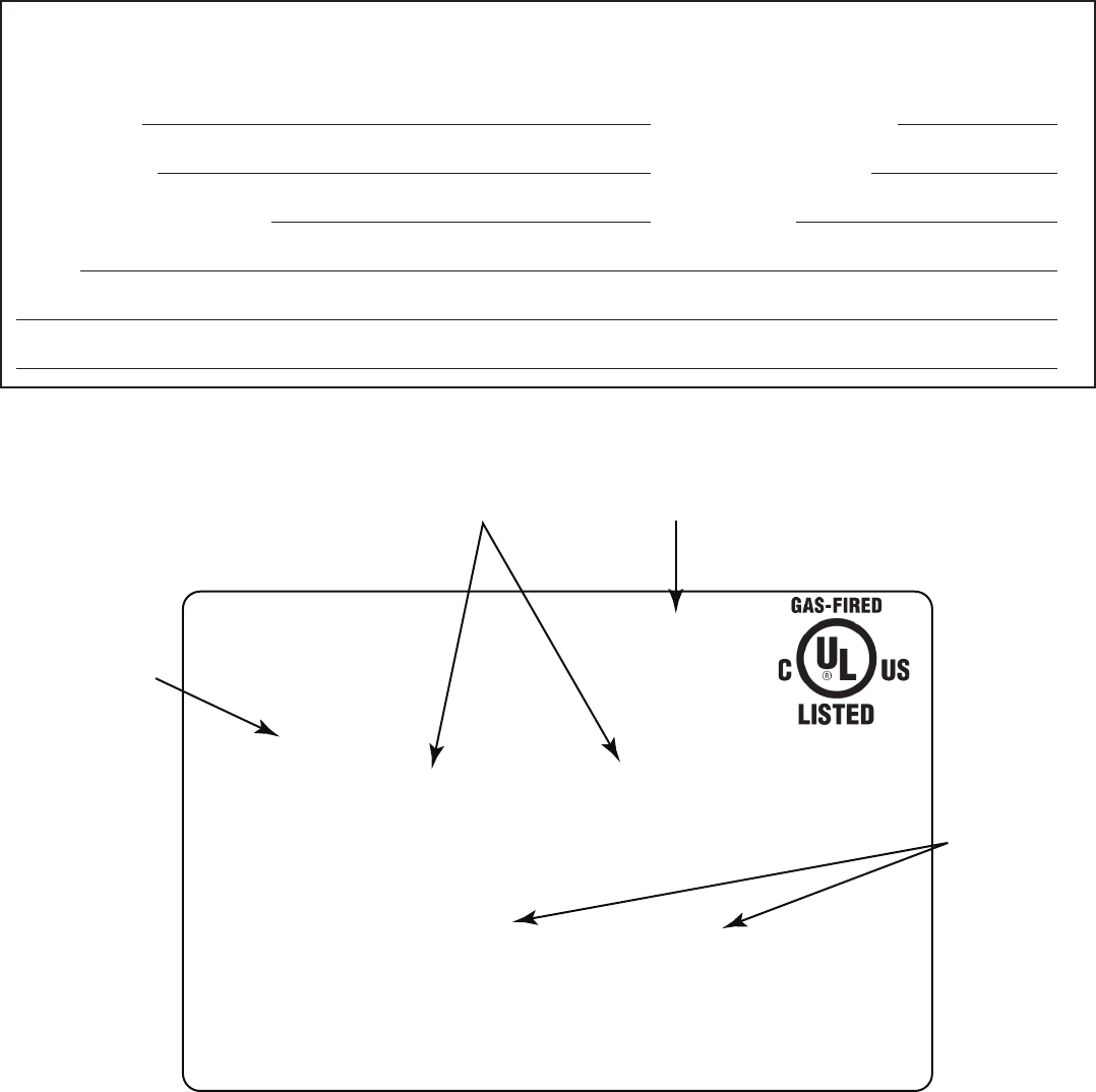
Listing Label Information/Location
The model information regarding your specifi c appliance can be found on the rating plate located in the control area of the
appliance.
XXXX
CERTIFIED
FOR CANADA
CERTIFIÉ POUR LE
CANADA
Hearth & Home Technologies Inc
1915 W. Saunders Street
Mt. Pleasant, IA 52641
SERIAL
NO. DE SÉRIE
ANSI Standard
MODEL MFG. DATE
MODÈLE DATE DE FAB.
GAS TYPE/TYPE DE GAZ NATURAL/NATUREL PROPANE
ALTITUDE 0-2000 2000-4000 FT/PI 0-2000 2000-4000 FT/PI
MAX INPUT/DÉBIT XX,XXX XX,XXX BTUH XX,XXX XX,XXX BTUH
MIN INPUT/DÉBIT XX,XXX XX,XXX BTUH XX,XXX XX,XXX BTUH
MANIFOLD PRESSURE/PRESSION TUBULAIRE
MAX. XX IN. W.C./C. D'EAU XX IN. W.C./C. D'EAU
MIN. XX IN. W.C./C. D'EAU XX IN. W.C./C. D'EAU
MIN. INLET PRESS. XX IN. W.C./C. D'EAU 1XX IN. W.C./C. D'EAU
FOR THE PURPOSE OF INPUT ADJUSTMENT
PRESS. MIN. D'ALIMENTATION
ORIFICE SIZE
DIAM. DE L'INJECTEUR XX/XX DIA. in./mm XX/XX DIA. in./mm
LESS THAN/MOINS DE 3 AMPÈRES., 115V., 60 Hz
DO NOT REMOVE OR COVER THIS LABEL.
VENTED GAS FIREPLACE - NOT FOR USE WITH SOLID FUEL.
FOYER À GAZ À ÉVACUATION - NE DOIT PAS ÊTRE UTILISÉ
AVEC UN COMBUSTIBLE SOLIDE.
XXXXXXXXX
XXXXXX
Serial #
Gas Type
Orifice
Size
Model #
Congratulations

Heatilator • GB4336/GB4992 • 4003-085 Rev H • 04/06 3
Table of Contents
1 Listing and Code Approvals 4
A. Appliance Certifi cation . . . . . . . . . . . . . . . . . . . . . . . . . 4
B. Glass Specifi cations . . . . . . . . . . . . . . . . . . . . . . . . . . 4
C. BTU Specifi cations . . . . . . . . . . . . . . . . . . . . . . . . . . . 4
D. High Altitude Installations . . . . . . . . . . . . . . . . . . . . . . 4
E. Non-Combustible Materials . . . . . . . . . . . . . . . . . . . . . 4
F. Combustible Materials . . . . . . . . . . . . . . . . . . . . . . . . . 4
2 Getting Started 5
A. Design and Installation Considerations . . . . . . . . . . . . 5
B. Negative Pressure . . . . . . . . . . . . . . . . . . . . . . . . . . . . 6
C. Tools and Supplies Needed . . . . . . . . . . . . . . . . . . . . . 7
D. Inspect the Appliance and Components . . . . . . . . . . . 7
3 Framing and Clearances 8
A. Select Appliance Location . . . . . . . . . . . . . . . . . . . . . . 8
B. Construct the Appliance Chase . . . . . . . . . . . . . . . . . . 9
C. Clearances . . . . . . . . . . . . . . . . . . . . . . . . . . . . . . . . 10
D. Mantel Projections . . . . . . . . . . . . . . . . . . . . . . . . . . . 11
4 Termination Locations 12
A. Vent Termination Minimum Clearances . . . . . . . . . . . 12
5 Vent Information and Diagrams 13
A. Vent Guidelines . . . . . . . . . . . . . . . . . . . . . . . . . . . . . 13
B. Vent System Confi guration . . . . . . . . . . . . . . . . . . . . 13
6 Vent Clearances and Framing 15
A. Pipe Clearances to Combustibles . . . . . . . . . . . . . . . 15
B. Wall Penetration Framing . . . . . . . . . . . . . . . . . . . . . 15
C. Vertical Penetration Framing . . . . . . . . . . . . . . . . . . . 15
7 Appliance Preparation 16
A. Installing Outside Air Kit Damper Assembly . . . . . . . 16
B. Gas and Electrical Connections . . . . . . . . . . . . . . . . 17
C. Securing and Leveling Appliance . . . . . . . . . . . . . . . 17
8 Installing Vent Pipe 18
A. Assemble Vent Sections . . . . . . . . . . . . . . . . . . . . . . 18
B. Attach Vent to Firebox Assembly . . . . . . . . . . . . . . . 18
C. Securing Vent Sections . . . . . . . . . . . . . . . . . . . . . . . 18
9 Gas Information 19
A. Fuel Conversion . . . . . . . . . . . . . . . . . . . . . . . . . . . . 19
B. Gas Pressure . . . . . . . . . . . . . . . . . . . . . . . . . . . . . . 19
C. Gas Connection . . . . . . . . . . . . . . . . . . . . . . . . . . . . . 19
D. High Altitude Installations . . . . . . . . . . . . . . . . . . . . . 20
10 Electrical Information 21
A. Recommendation for Wire . . . . . . . . . . . . . . . . . . . . . 21
B. Connecting to the Appliance . . . . . . . . . . . . . . . . . . . 21
C. Intellifi re Ignition System Wiring . . . . . . . . . . . . . . . . 21
D. Standing Pilot Ignition System Wiring . . . . . . . . . . . . 22
E. Junction Box Installation . . . . . . . . . . . . . . . . . . . . . . 23
11 Finishing 24
A. Mantel Projections . . . . . . . . . . . . . . . . . . . . . . . . . . . 24
B. Facing Material . . . . . . . . . . . . . . . . . . . . . . . . . . . . . 24
12 Appliance Setup 25
A. Remove the Shipping Materials . . . . . . . . . . . . . . . . 25
B. Clean the Appliance . . . . . . . . . . . . . . . . . . . . . . . . . 25
C. Accessories . . . . . . . . . . . . . . . . . . . . . . . . . . . . . . . . 25
D. Install the Refractory . . . . . . . . . . . . . . . . . . . . . . . . . 25
E. Lava Rock, Vermiculite, Rockwool Placement . . . . . 25
F. Log Removal/Replacement . . . . . . . . . . . . . . . . . . . . 26
G. Glass Doors . . . . . . . . . . . . . . . . . . . . . . . . . . . . . . . . 27
H. Hood . . . . . . . . . . . . . . . . . . . . . . . . . . . . . . . . . . . . . 27
I. Air Shutter Setting . . . . . . . . . . . . . . . . . . . . . . . . . . . 27
13 Operating Instructions 28
A. Before Lighting Appliance . . . . . . . . . . . . . . . . . . . . . 28
B. Check Appliance Draft . . . . . . . . . . . . . . . . . . . . . . . . 29
C. High Limit Safety Switch . . . . . . . . . . . . . . . . . . . . . . 29
D. Lighting the Appliance . . . . . . . . . . . . . . . . . . . . . . . . 30
E. After the Appliance is Lit . . . . . . . . . . . . . . . . . . . . . . 32
F. Frequently Asked Questions . . . . . . . . . . . . . . . . . . . 32
14 Troubleshooting 33
A. Standing Pilot Ignition System . . . . . . . . . . . . . . . . . . 33
B. Intellifi re Ignition System . . . . . . . . . . . . . . . . . . . . . . 35
15 Maintaining and Servicing the Appliance 37
16 Reference Materials 39
A. Appliance Dimension Diagram . . . . . . . . . . . . . . . . . 39
B. Service Parts List . . . . . . . . . . . . . . . . . . . . . . . . . . . 40
C. Optional Components . . . . . . . . . . . . . . . . . . . . . . . . 48
D. Limited Lifetime Warranty . . . . . . . . . . . . . . . . . . . . . 51
E. Contact Information . . . . . . . . . . . . . . . . . . . . . . . . . . 52
Note: An arrow () found in the text signifi es change in content.
4 Heatilator • GB4336/GB4992 • 4003-085 Rev H • 04/06
1
Listing and Code Approvals
A. Appliance Certifi cation
This product is listed to ANSI standards for “Vented Gas
Fireplaces” and “Gas Fired Appliances for Use at High Al-
titudes”.
This model (natural gas and propane) can be installed in a
bedroom (in the United States) which has a total volume of
unconfi ned space appropriate to the particular installation.
Refer to the National Fuel Gas Code ANSI Z223.1/NFPA54
(current edition), The Uniform Mechanical Code - (cur-
rent edition), and local building offi cials for the options al-
lowed in obtaining an effective bedroom volume of uncon-
fi ned space.
This model (natural gas and propane) can be installed in a
bedroom (in Canada) if a thermostat is installed with the ap-
pliance. Consult local code authorities.
Do NOT use this appliance if any part has been under
water. Immediately call a qualifi ed service technician
to inspect the appliance and to replace any part of the
control system and any gas control which has been
under water.
WARNING
MODELS: GB4336/GB4942 Series
LABORATORY: Underwriters Laboratories, Inc. (UL)
TYPE: B-Vent Gas Appliance
STANDARD: ANSI Z21.50-2000/CSA 2.33-2000, IR41,
P4 and IR55
NOT INTENDED FOR USE AS A PRIMARY HEAT
SOURCE. This appliance is tested and approved as either
supplemental room heat or as a decorative appliance. It
should not be factored as primary heat in residential heating
calculations.
Note: This installation must conform with local codes. In the
absence of local codes you must comply with the National
Fuel Gas Code, ANSI Z223.1-latest edition in the U.S.A.
and the CAN/CGA B149 Installation Codes in Canada.
B. Glass Specifi cations
Hearth & Home Technologies appliances manufactured with
tempered glass may be installed in hazardous locations such
as bathtub enclosures as defi ned by the Consumer Product
Safety Commission (CPSC). The tempered glass has been
tested and certifi ed to the requirements of ANSI Z97.1 and
CPSC 16 CFR 1202 (Safety Glazing Certifi cation Council
SGCC# 1595 and 1597. Architectural Testing, Inc. Reports
02-31919.01 and 02-31917.01).
This statement is in compliance with CPSC 16 CFR Section
1201.5 “Certifi cation and labeling requirements” which refers
to 15 U.S. Code (USC) 2063 stating “…Such certifi cate shall
accompany the product or shall otherwise be furnished to
any distributor or retailer to whom the product is delivered.”
Some local building codes require the use of tempered glass
with permanent marking in such locations. Glass meeting
this requirement is available from the factory. Please contact
your dealer or distributor to order.
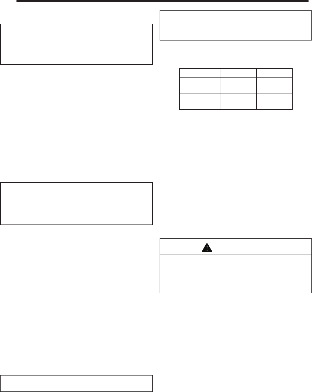
C. BTU Specifi cations
D. High Altitude Installations
U.L. Listed gas appliances are tested and approved without
requiring changes for elevations from 0 to 2000 feet in the
U.S.A. and Canada.
When installing this appliance at an elevation above 2000 ft,
it may be necessary to decrease the input rating by chang-
ing the existing burner orifi ce to a smaller size. Input rate
should be reduced by 4% for each 1000 ft above a 2000 ft
elevation in the U.S.A., or 10% for elevations between 2000
and 4500 ft in Canada. If the heating value of the gas has
been reduced, these rules do not apply. To identify the prop-
er orifi ce size, check with the local gas utility.
If installing this appliance at an elevation above 4500 ft (in
Canada), check with local authorities.
Note: Glass doors are not optional in the Commonwealth
of Massachusetts. They are required.
E. Non-Combustible Materials
Materials that are reported as passing ASTM E 136, Stan-
dard Test Method for Behavior of Materials in a Vertical
Tube Furnace at 750° C, shall be considered non-combus-
tible materials.
F. Combustible Materials
Materials made of or surfaced with wood, compressed pa-
per, plant fi bers, plastics, or other material that can ignite and
burn, whether fl ame proofed or not, or whether plastered or
unplastered shall be considered combustible materials.
Geneva 4336 Series 4942 Series
Input Rate (NG) 34,000 BTU/hr. 36,000 BTU/hr.
Input Rate (LP) 34,000 BTU/hr. 36,000 BTU/hr.
Orifi ce Size (LP) #52 #51
Orifi ce Size (NG) #35 #32
Heatilator • GB4336/GB4992 • 4003-085 Rev H • 04/06 5
A. Design and Installation Considerations
Heatilator B-vent gas appliances are designed to operate
with all exhaust gases expelled to the outside of the building,
and combustion air pulled from the room.
Check building codes prior to installation.
• Installation MUST comply with local, regional,
state and national codes and regulations.
• Consult insurance carrier, local building, fire
offi cials or authorities having jurisdiction about
restrictions, installation inspection, and permits.
CAUTION
When planning an appliance installation, it’s necessary to
determine the following information before installing:
• Where the appliance is to be installed. See Section 3.
• The vent system confi guration to be used. See Sections
4 and 5.
• Gas supply piping. See Section 9.
• Electrical wiring. See Sections10
• Framing and finishing details. See Sections 3, 6
and 11.
• Whether optional accessories—devices such as a fan, wall
switch, or remote control—are desired. See Section 10.
Keep appliance dry.
• Mold or rust may cause
odors.
• Water may damage controls.
WARNING
2
2 Getting Started
6 Heatilator • GB4336/GB4992 • 4003-085 Rev H • 04/06
B. Negative Pressure
Asphyxiation Risk
• Negative pressure can cause spillage of
combustion fumes and soot.
• Fire needs to draft properly for safe
operation.
WARNING
To minimize the effects of negative air pressure, the follow-
ing must be considered:
• Install the outside air kit. Install the intake on the side of
the house towards prevailing winds during the heating
season.
• Ensure adequate outdoor air is supplied for combustion
appliances and exhaust equipment.
• Ensure furnace and air conditioning return vents are not
located in the immediate vicinity of the fi replace.
• Avoid installing the fi replace near doors, walkways or small
isolated spaces.
• Recessed lighting should be a “sealed can” design; attic
hatches weather stripped or sealed; attic mounted duct
work and air handler joints and seams taped or sealed.
• Basement installations should be avoided due to stack
effect. Stack effect creates negative pressure in lower
levels. Hearth & Home Technologies recommends the
use of direct vent fi replaces in basements.
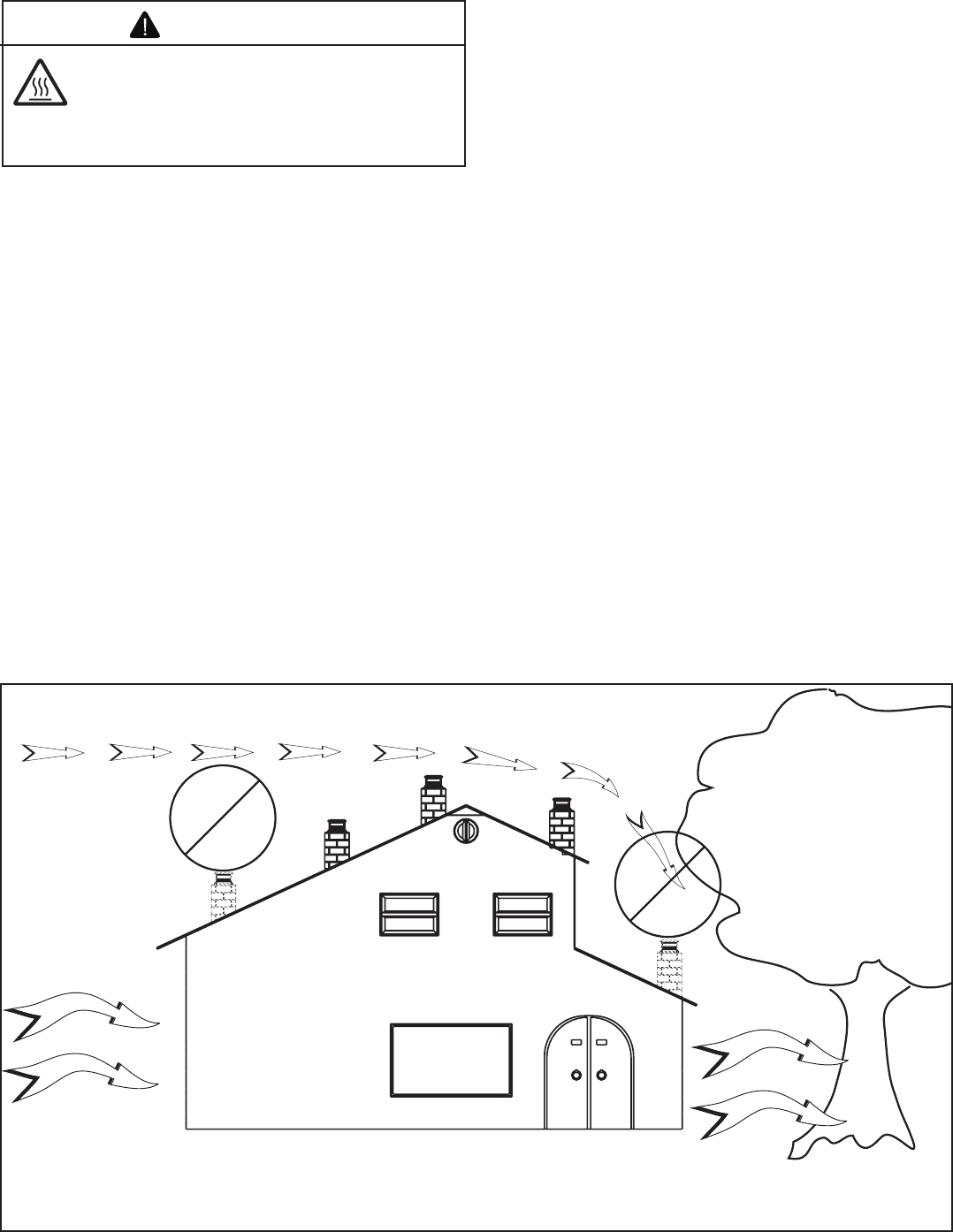
Location of the fi replace and chimney will affect performance.
As shown in Figure 2.1 the chimney should:
• Be installed through the warm airspace enclosed by the
building envelope. This helps to produce more draft,
especially during lighting and die-down of the fi re.
• Penetrate the highest part of the roof. This minimizes the
effects of wind turbulence.
• Be located away from trees, adjacent structures, uneven
roof lines and other obstructions.
Offsets can restrict draft so their use should be minimized.
Consider the fi replace location relative to fl oor and ceiling
and attic joists.
Recommended
Location
Marginal
Location
Location
Not
Recommended
Recommended
Location
Multi-level Roofs
Windward
Leeward
Location
Not
Recommended
Figure 2.1 Recommended Chimney Locations
Draft is the pressure difference needed to vent fi replaces
successfully. Considerations for successful draft include:
• Preventing negative pressure.
• Location of fi replace and chimney.
Negative Pressure
Negative pressure results from the imbalance of air avail-
able for the fi replace to operate properly. Causes for this
imbalance include:
• Exhaust fans (kitchen, bath, etc.).
• Range hoods.
• Combustion air requirements for furnaces, water heaters
and other combustion appliances.
• Clothes dryers.
• Location of return-air vents to furnace or air
conditioning.
• Imbalances of the HVAC air handling system.
• Upper level air leaks (recessed lighting, attic hatch
opening, duct leaks).
Heatilator • GB4336/GB4992 • 4003-085 Rev H • 04/06 7
Inspect appliance and components for
damage. Damaged parts may impair safe
operation.
• Do NOT install damaged components.
• Do NOT install incomplete components.
• Do NOT install substitute components.
Report damaged parts to dealer.
WARNING
Hearth & Home Technologies disclaims any
responsibility for, and the warranty will be
voided by, the following actions:
• Installation and use of any damaged appliance or
vent system component.
• Modifi cation of the appliance or vent system.
• Installation other than as instructed by Hearth & Home
Technologies.
• Improper positioning of the gas logs or the glass
door.
• Installation and/or use of any component part not
approved by Hearth & Home Technologies.
Any such action may cause a fi re hazard.
WARNING
C. Tools and Supplies Needed
Before beginning the installation be sure that the following
tools and building supplies are available.
Reciprocating saw Framing material
Pliers Hi temp caulking material
Hammer Gloves
Phillips screwdriver Framing square
Flat blade screwdriver Electric drill and bits (1/4 in.)
Plumb line Safety glasses
Level Manometer
Voltmeter Tape measure
Non-corrosive leak check solution
1/2 - 3/4 in. length, #6 or #8 Self-drilling screws
One 1/4 in. female connection (for optional fan).
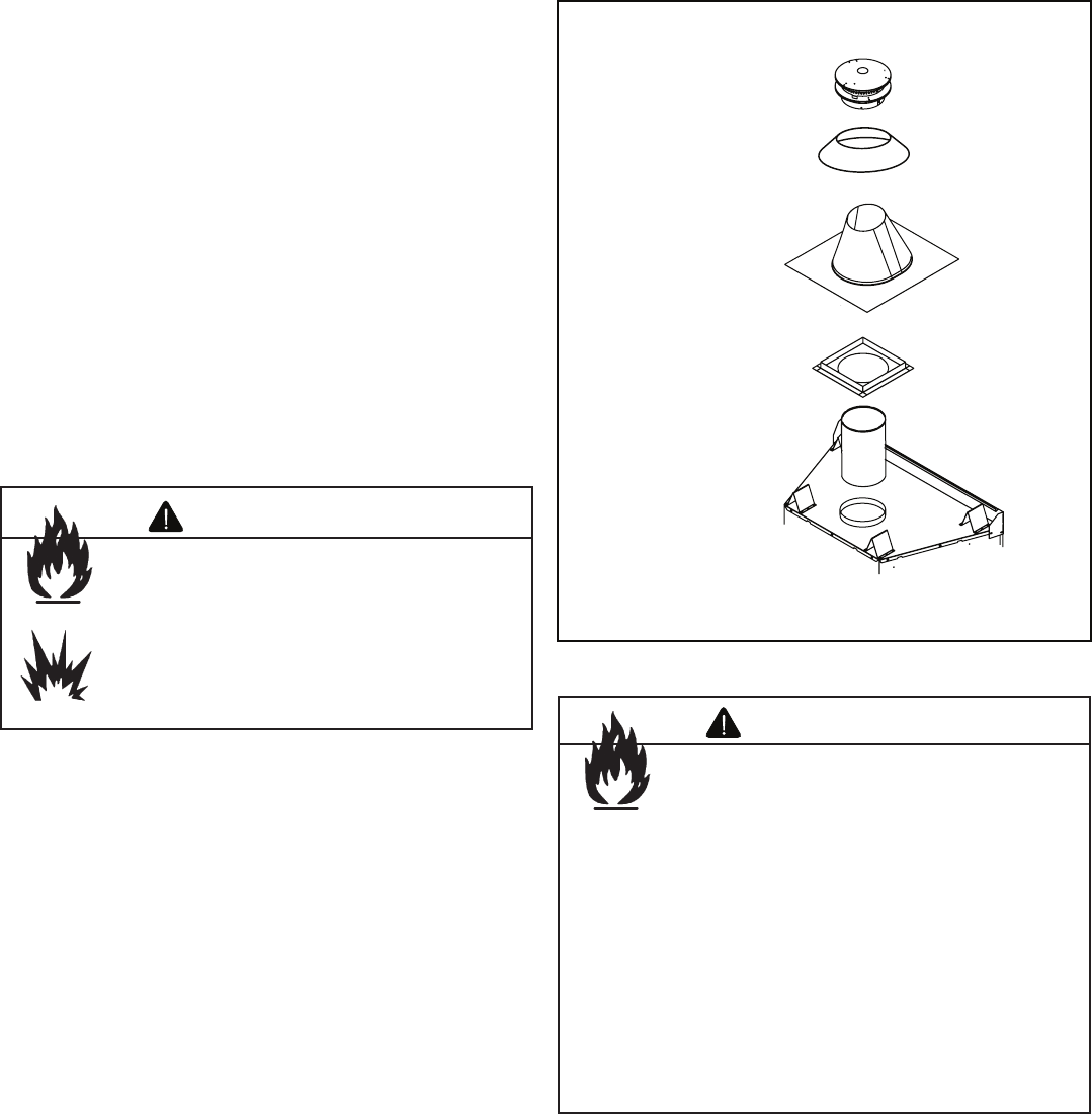
D. Inspect the Appliance and Components
The following B-vent components are needed for installa-
tion. See Figure 2.2.
• Appliance
• Pipe components
• Firestops
• Attic insulation shield
• Elbows
• Strapping
• Roof fl ashing or chase top
• Termination cap
• Storm Collar
• Carefully remove the appliance and components from the
packaging.
• The vent system components and trim doors are shipped
in separate packages.
• The gas logs may be packaged separately and must be
fi eld installed.
• Report to your dealer any parts damaged in shipment,
particularly the condition of the glass.
• Read all of the instructions before starting the
installation. Follow these instructions carefully
during the installation to ensure maximum safety and
benefi t.
Vertical
Termination
Cap
Roof
Flashing
Ceiling
Firestop
B-Vent Pipe
Sections
Storm
Collar
Figure 2.2 Typical Vertical Installation
8 Heatilator • GB4336/GB4992 • 4003-085 Rev H • 04/06
Note:
• Illustrations refl ect typical installations and are FOR
DESIGN PURPOSES ONLY.
• Illustrations/diagrams are not drawn to scale.
• Actual installation may vary due to individual design
preference.
Fire Risk
Provide adequate clearance:
• Around air openings.
• For service access.
Locate appliance away from traffi c areas.
WARNING
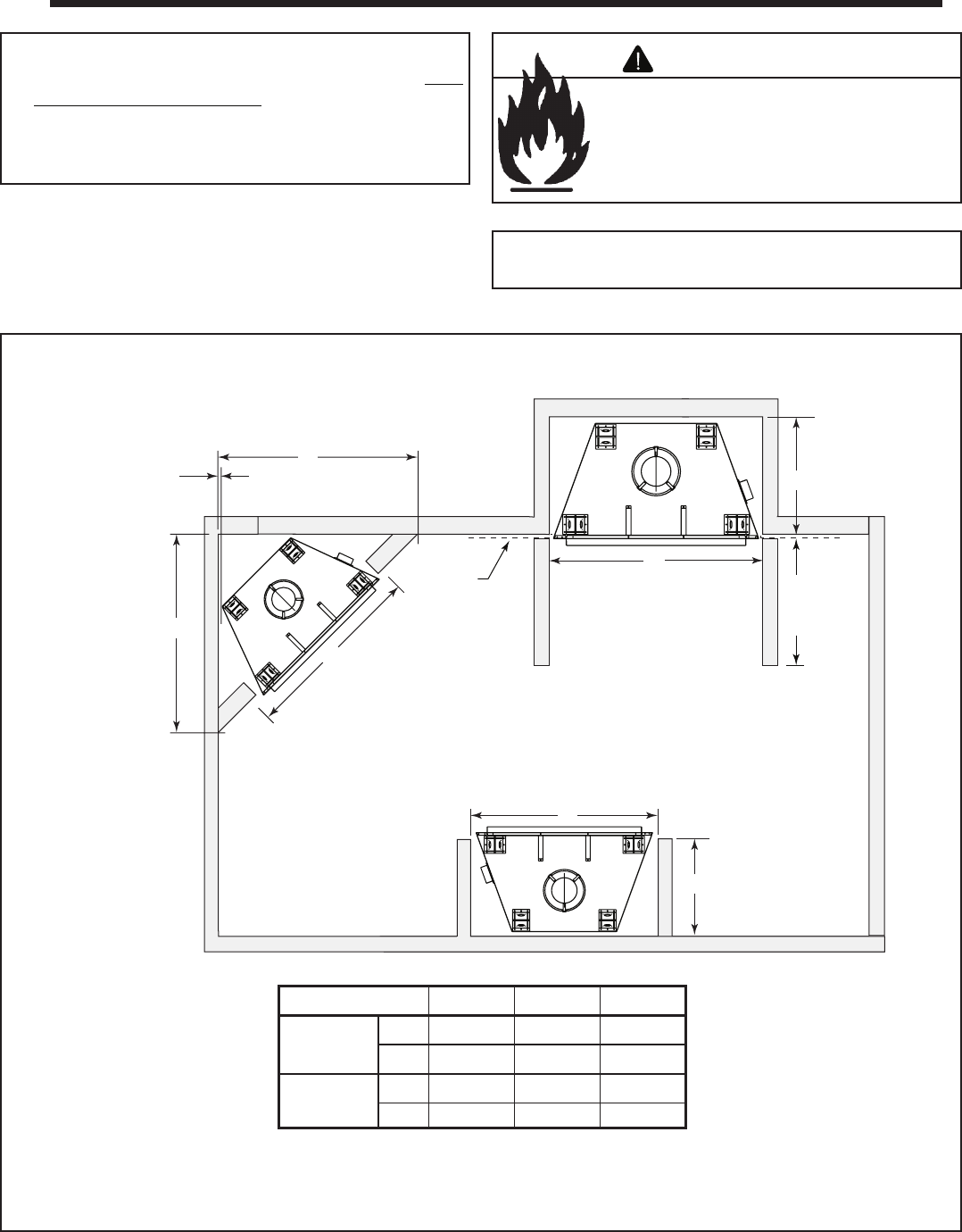
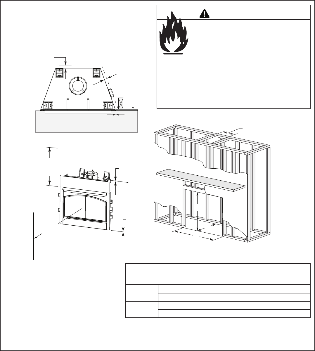
A. Select Appliance Location
When selecting a location for your appliance it is important to
consider the required clearances to walls (See Figure 3.1).
Note: For actual appliance dimensions refer to
Section 16.
In addition to these framing dimensions, also reference the
following sections:
• Clearances and Mantel Projections (Sections 3.C. and 3.D.)
• Vent Clearances and Framing (Section 6)
A
A
A
C
B
B
1/2 in. (13 mm) min.
appliance
to combustibles
Alcove
Installation
C
Drywall 48 in.
(1219 mm)
max.
Figure 3.1 Appliance Locations
3
3 Framing and Clearances
Model # A B C
4336 Series in. 43 51-3/4 24
mm 1092 1314 610
4942 Series in. 49 56 24
mm 1245 1422 610
Heatilator • GB4336/GB4992 • 4003-085 Rev H • 04/06 9
B. Construct the Appliance Chase
A chase is a vertical boxlike structure built to enclose the gas
appliance and/or its vent system. Vertical vents that run on
the outside of a building may be, but are not required to be,
installed inside a chase.
Construction of the chase may vary with the type of build-
ing. These instructions are not substitutes for the require-
ments of local building codes. Local building codes MUST
be checked.
Chases should be constructed in the manner of all outside
walls of the home to prevent cold air drafting problems. The
chase should not break the outside building envelope in any
manner.
Walls, ceiling, base plate and cantilever fl oor of the chase
should be insulated. Vapor and air infi ltration barriers should
be installed in the chase as per regional codes for the rest of
the home. Additionally, Hearth & Home Technologies recom-
mends that the inside surfaces be sheetrocked and taped for
maximum air tightness.
To further prevent drafts, gas line holes and other openings
should be caulked with high temperature caulk or stuffed
with unfaced insulation. If the appliance is being installed
on a cement slab, we recommend that a layer of plywood
be placed underneath to prevent conducting cold up into the
room.
Fire Risk
• Construct chase to all clearance
specifi cations in manual.
• Locate and install appliance to all
clearance specifi cations in manual.
WARNING
10 Heatilator • GB4336/GB4992 • 4003-085 Rev H • 04/06
C. Clearances
C
B
A
Per Vent Manufacturer’s
Specifications
30 in.
(762 mm)
to ceiling
0 in.
Drywall
0 in.
1/2 in.
(13 mm)
1/2 in.
(13 mm)
Combustible flooring may be installed
next to the front of the appliance.
36 in.
(914 mm)
Combustible Object
0 in.to level
of standoffs
Figure 3.2 Clearances to Combustibles
Fire Risk
Odor Risk
• Install appliance on hard metal or wood
surfaces extending full width and depth
of appliance.
• Do NOT install appliance directly on
carpeting, vinyl, tile or any combustible
material other than wood.
• Do NOT place furniture or any other
combustible household objects within
36 in. of the appliance front.
WARNING
Model #
A
Rough Opening
(Width)
B
Rough Opening
(Height)
C
Rough Opening
(Depth)
4336 Series in. 43 39-3/4 24
mm 1092 1010 610
4942 Series in. 49 39-3/4 24
mm 1245 1010 610
Heatilator • GB4336/GB4992 • 4003-085 Rev H • 04/06 11
Measured from top of hood (in inches)
3 - 12
13
14
15
16
17
18
13-1/4 14
14-3/4
15-1/2
16-1/4
17
17-3/4
30 in. minimum
to ceiling
0 - 3
9-3/8
Figure 3.3 Clearances to Mantels or Other Combustibles Above
Appliance
1 in. (25mm) min.
to perpendicular wall
A
3-1/2 in. (89 mm) min.
from fireplace opening
to perpendicular wall
B
48 in.
(1219 mm)
max.
Mantel Leg or
Perpendicular Wall
Top of
Appliance Drywall
A
B
Figure 3.4 Clearances to Combustible Mantel Legs or Wall Projec-
tions (acceptable on both sides of opening)
D. Mantel Projections
12 Heatilator • GB4336/GB4992 • 4003-085 Rev H • 04/06
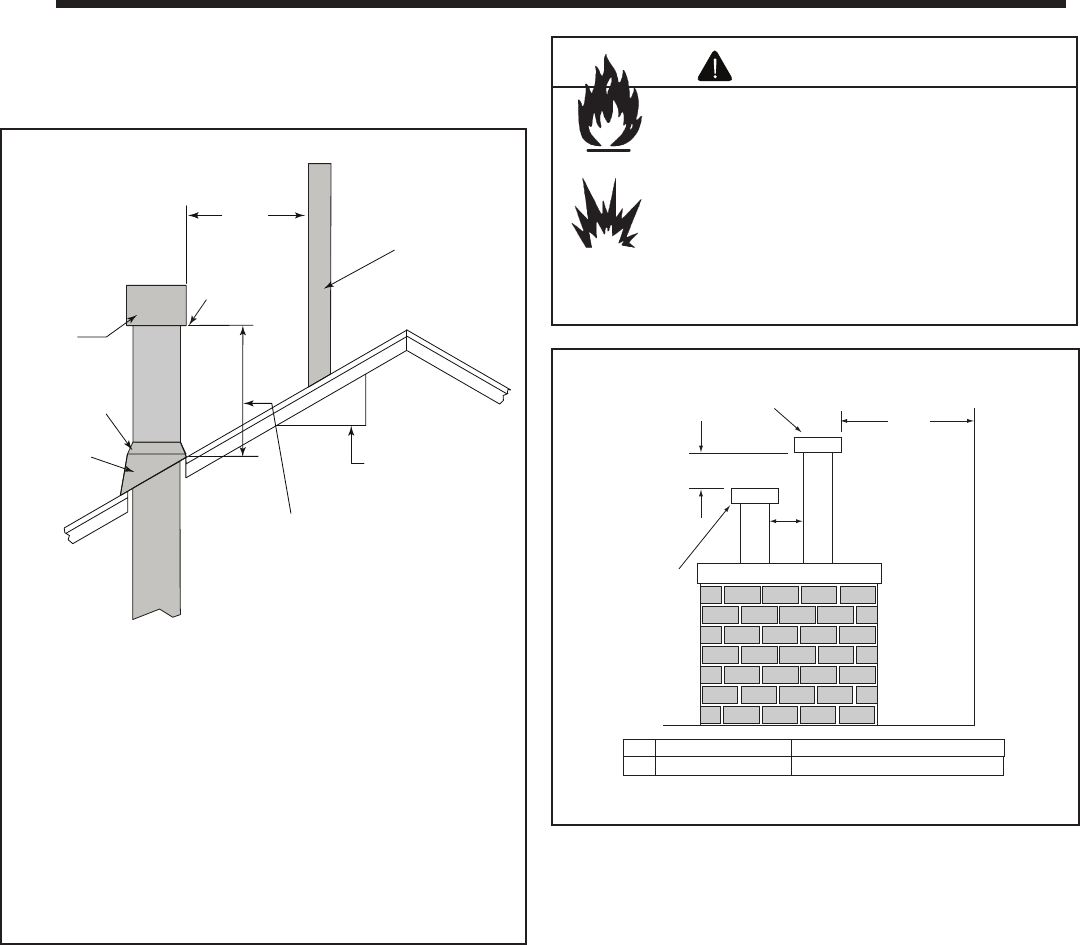
A. Vent Termination Minimum Clearances
Fire Risk
Explosion Risk
• Do not pack air space with insulation or
other materials.
Maintain vent clearance to combustibles as
specifi ed.
WARNING
Failure to keep insulation or other materials
away from vent pipe may cause fi re.
Gas Termination Wood & Fuel Oil Termination
A 6 in. (152 mm) 20 in. (508 mm)
Gas, Wood or Fuel
Oil Termination
8 ft
(2.44 m)
(minimum) to
Perpendicular
Wall
(gas only)
18 in.
(457 mm)
A
Gas
Termination
Figure 4.2 Multiple Vertical Termination
Figure 4.1 specifi es minimum vent heights for various
pitched roofs.
4
4 Termination Locations
12
X
8 ft
(2.44 mm)
Lowest
Discharge
Opening
Termination
Cap
Roof Pitch
is X / 12
Vertical
wall
H (min.) - Minimum height
from roof to lowest
discharge opening.
Roof Pitch H (Min.) Ft. Roof Pitch H (Min.) Ft.
Flat to 6/12 1.0* Over 11/12 to 12/12 4.0
Over 6/12 to 7/12 1.25* Over 12/12 to 14/12 5.0
Over 7/12 to 8/12 1.5* Over 14/12 to 16/12 6.0
Over 8/12 to 9/12 2.0* Over 16/12 to 18/12 7.0
Over 9/12 to 10/12 2.5 Over 18/12 to 20/12 7.5
Over 10/12 to 11/12 3.25 Over 20/12 to 21/12 8.0
* 3 ft. minimum in snow regions
Storm Collar
Roof
Flashing
Figure 4.1
Minimum Height from Roof to Lowest Discharge Opening
Heatilator • GB4336/GB4992 • 4003-085 Rev H • 04/06 13
Fire Risk
Explosion Risk
Asphyxiation Risk
Do NOT connect this gas appliance to a
chimney fl ue serving a separate solid-fuel
or gas burning appliance.
• Vent this appliance directly outside.
• Use separate vent system for this
appliance.
May impair safe operation of this appliance or
other appliances connected to the fl ue.
WARNING
ALL vent configuration specifications MUST be
followed.
• This product is tested and listed to appliance and
vent manufacturer’s specifi cations.
• Appliance performance will suffer if specifi cations
are not followed.
CAUTION
Minimum
clearances are
per vent
manufacturer's
specifications
Metal
plumber's strap
secured to
framing
Vent supports are per
vent manufacturer's
specifications
9 ft (2.74 m) min.
40 ft (12.19 m) max.
Figure 5.1 Vertical Termination Clearances
5
5 Vent Information and Diagrams
A. Vent Guidelines
Fire Risk
Asphyxiation Risk
This appliance requires the specifi ed pipe
for operation.
• Incorrect pipe may cause spillage,
condensation and overheating.
WARNING
These models require the following size B-Vent double wall
vent pipe.
• Follow pipe manufacturer’s installation guidelines when
installing the appliance.
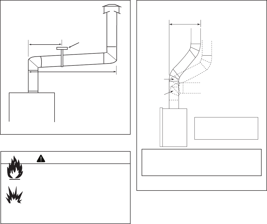
B. Vent System Confi guration
• Rise to Run Ratio: 2:1
• Maximum Total Horizontal Run: 20 ft
• Minimum Total Vertical Rise: 9 ft
• Maximum Total Vertical Rise: 40 ft
• Maximum Number of Elbows: Four 45°
• Maximum Number of 90° Elbows: Four
A maximum of four 90-degree elbows may be used on
this appliance when used in confunction with the fi xed
glass doors listed below:
• DF361B/S
• DF421B/S
Model Pipe Size
GB4336 Series in. 6
mm 152
GB4942 Series in. 6
mm 152
14 Heatilator • GB4336/GB4992 • 4003-085 Rev H • 04/06
45°
Elbow
90°
Elbow
Offsets exceeding
45° adapt horizontal
limitations
Maximum
horizontal
20 ft (6.1 m)
Note: Maximum horizontal
distance is 50% of vertical
vent height.
Maximum horizontal run is 50% of
vertical. Horizontal run cannot be
more than 20 ft. (6.1 m).
Vent supports
are per vent
manufacturer’s
specifications.
Metal
Plumbers'
Strap
Figure 5.2 Maximum Horizontal Run
Fire Risk
Explosion Risk
Insulation and other combustibles must not
infringe on clearances.
• ALWAYS maintain specifi ed clearances
around venting and fi restop systems.
• Install fi restops as specifi ed.
Failure to keep insulation or other material
away from vent pipe may cause fi re.
WARNING
Figure 5.3 Maximum Horizontal Run
Note: 90-degree elbows are not allowed without a
fi xed glass door. Only 45-degree elbows or less are
allowed. A straight section is not reuqired before the
fi r s t e l b o w .
Heatilator • GB4336/GB4992 • 4003-085 Rev H • 04/06 15
A. Pipe Clearances to Combustibles
Fire Risk
Explosion Risk
Maintain vent clearance to combustibles as
specifi ed.
• Do not pack air space with insulation or
other materials.
• National building codes recommend
using attic shield to keep loose materials/
insulation from contacting vent.
Failure to keep insulation or other materials
away from vent pipe may cause fi re.
WARNING Do not pack with insulation
or other materials.
Use manufacturer's
installation instructions for
framing dimensions
Figure 6.1 Exterior Wall Hole
6
6 Vent Clearances and Framing
B. Wall Penetration Framing
Follow vent pipe manufacturer’s instructions for all clear-
ances around pipe. For a wall penetration consult B-vent pipe manufacturer’s
instructions. Use same dimensional framing materials as
those used in the wall construction.
Note: This appliance MUST terminate vertically.
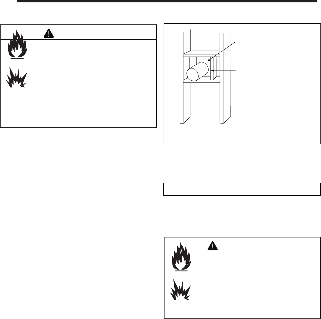
C. Vertical Penetration Framing
Use B-vent manufacturer’s fi restops to provide adequate
clearances.
Fire Risk
Keep loose materials or blown insulation
from touching the vent pipe.
• National building codes recommend
using attic shield to keep loose materials/
insulation from contacting vent.
• Hearth & Home Technologies requires
the use of an attic shield.
WARNING
16 Heatilator • GB4336/GB4992 • 4003-085 Rev H • 04/06
7
7 Appliance Preparation
Sharp Edges
• Wear protective gloves
and safety glasses during
installation.
CAUTION
Fire Risk
Asphyxiation Risk
Maintain vent clearance to combustibles as
specifi ed.
• Do not pack air space with insulation or
other materials.
• National building codes recommend
using attic shield to keep loose materials/
insulation from contacting vent.
Failure to keep insulation or other materials
away from vent pipe may cause fi re.
WARNING
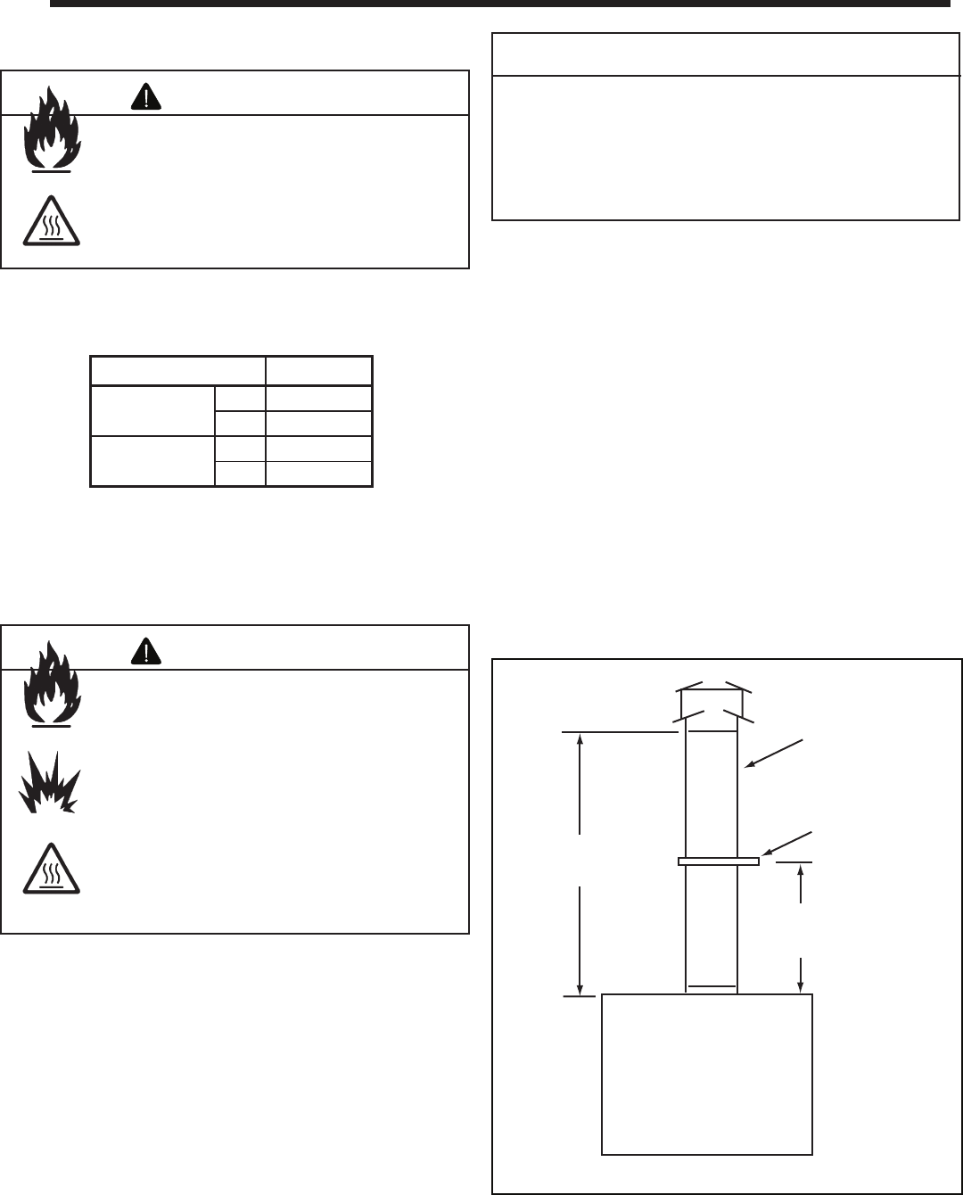
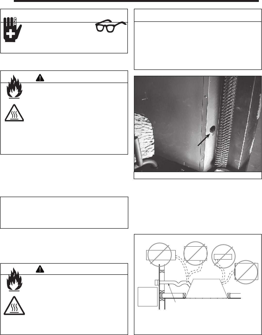
A. Installing Outside Air Kit Damper Assembly
This appliance will operate correctly only if adequate ventia-
tion is provided to allow proper draft to the system.
An outside air kit is available as an optional feature with this
appliance. An outside air kit helps to decrease the amount
of room air taken by utilizing outside air for combustion. We
strongly recommend that it be installed.
Outlet placed
higher than 3 ft
below the
termination cap
Attic space
Garage or
combustible
liquids storage
Outlet blocked by
snow, leaves, etc.
Clear area
outside
house or in
ventilated
crawl space
YES
NO
NO
NO
NO
Use only duct materials specified
by manufacturer (preferably with
short run or mainly straight duct,
except small dip for cold air trap
which will help prevent flow of cold air).
Factory-built
fireplace
Figure 7.2 Outside Combustion Air Placement
Figure 7.1 Outside Air Kit Handle Location
• The outside air kit can only be installed on the left side of
the appliance.
• Refer to the installation instructions provided with the
kit.
Note: The outside air kit inlet thimble should be positioned
in a manner that will not allow snow, leaves, etc. to block
the inlet. A 3 ft. (.91 m) minimum height difference must be
maintained from the top of the uppemost chimney section to
the outside combustion air inlet. Reference Section 2.
Fire Risk
Asphyxiation Risk
Do not draw outside combustion air from:
• Wall, fl oor or ceiling cavity.
• Enclosed space such as an attic or
garage.
• Close proximity to exhaust vents or
chimneys.
Fumes or odor may result.
WARNING
Risk of Smoke Spillage
Outside air inlet must be located to prevent blockage
from:
• Leaves
• Snow/ice
• Other debris
Blockage may cause combustion air starvation.
CAUTION
• Grasp the small black handle located on the side of the
appliance. See Figure 7.1.
• Lift handle and pull towards front. Outside air door should
open.
• Place handle in slot on bracket so outside air door remains
open.
• When through burning appliance, grasp handle and push
outside air door closed.
Heatilator • GB4336/GB4992 • 4003-085 Rev H • 04/06 17
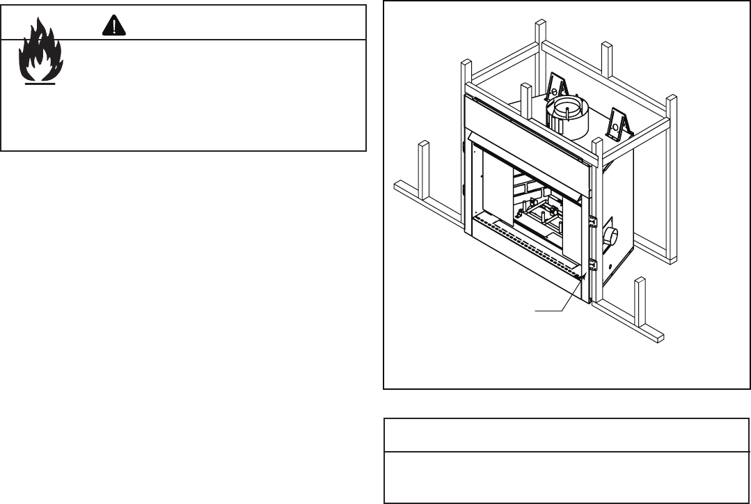
Do NOT notch into the framing around the appliance
spacers.
CAUTION
Nailing Tabs
(both sides)
Figure 7.3 Proper Positioning, Leveling and Securing of an
Appliance
C. Securing and Leveling Appliance
The diagram shows how to properly position, level, and se-
cure the appliance (see Figure 7.3). Nailing tabs are pro-
vided to secure the appliance to the framing members.
• Place the appliance into position.
• Level the appliance from side to side and front to back.
• Shim the appliance as necessary. It is acceptable to use
wood shims.
• Bend out nailing tabs on each side.
• Keep nailing tabs fl ush with the framing.
• Secure the appliance to the framing by using nails or
screws through the nailing tabs.
B. Gas and Electrical Connections
Ensure that gas and electrical connections are installed at
this time. Refer to Sections 9 and 10.
Fire Risk!
• Prevent contact with sagging, loose
insulation.
• Do NOT install against combustible
materials such as exposed insulation,
plastic and insulation backer.
WARNING
18 Heatilator • GB4336/GB4992 • 4003-085 Rev H • 04/06
Three tabs
A. Assemble Vent Sections
This B-Vent appliance requires 6 in. B-vent double-wall pipe.
Follow the pipe manufacturer’s installation guidelines when
installing the appliance. This will ensure proper operation
and prevent safety hazards.
8
8 Installing Vent Pipe
Fire Risk
Exhaust Fumes Risk
Impaired Performance of Appliance.
• Assemble pipe sections per B-Vent
manufacturer’s instructions.
• Use support tabs for screws.
• Pipe may separate if not properly
joined.
WARNING
Figure 8.1 Attaching Vent to Firebox
B. Attach Vent to Firebox Assembly
Three tabs extend from appliance collar shield. Attach tabs
to fi rst section of B-vent pipe using self-tapping 1/4 in. screws
supplied with appliance. See Figure 8.1.
C. Securing Vent Sections
Secure vent sections with vent supports following B-vent
manufacturer’s instructions.
Fire Risk
Explosion Risk
Asphyxiation Risk
Use vent run supports per vent manufacturer’s
installation instructions.
Connect vent sections per vent manufacturer’s
installation instructions.
• Maintain all clearances to combustibles.
• Maintain specifi ed slope (if required).
Improper support may allow vent to sag or
separate.
WARNING
Heatilator • GB4336/GB4992 • 4003-085 Rev H • 04/06 19
A. Fuel Conversion
Before making gas connections ensure appliance being in-
stalled is compatible with the available gas type.
Any natural or propane gas conversions necessary to meet
the appliance and locality needs must be made by a quali-
fi ed technician using Hearth & Home Technologies specifi ed
and approved parts.
B. Gas Pressure
Proper input pressures are required for optimum appliance
performance. Gas line sizing requirements need to be made
following NFPA51.
C. Gas Connection
Refer to Reference Section 16 for location of gas line access
in appliance.
Note: Have the gas supply line installed in accordance
with local building codes, if any. If not, follow ANSI
223.1. Installation should be done by a qualifi ed installer
approved and/or licensed as required by the locality. (In
the Commonwealth of Massachusetts installation must be
performed by a licensed plumber or gas fi tter.)
Note: A listed (and Commonwealth of Massachusetts
approved) 1/2 in. (13 mm) T-handle manual shut-off valve
and fl exible gas connector are connected to the 1/2 in.
(13 mm) control valve inlet.
• If substituting for these components, please consult
local codes for compliance.
Pressure requirements for appliance are shown in table be-
low. Minimum pressures must be met when other household
gas appliances are operating.
Pressure Natural Gas Propane
Minimum Inlet Pressure 5.0 in. w.c. 11.0 in. w.c.
Maximum Inlet Pressure 7.0 in. w.c. 14.0 in. w.c.
Manifold Pressure 3.5 in. w.c. 10.0 in. w.c.
WARNING
Gas Leak Risk
• Support control when attaching pipe to
prevent bending gas line.
9
9 Gas Information
Fire Risk
Explosion Risk
High pressure will damage valve.
• Disconnect gas supply piping BEFORE
pressure testing gas line at test pressures
above 1/2 psig.
• Close the manual shutoff valve BEFORE
pressure testing gas line at test pressures
equal to or less than 1/2 psig.
WARNING
• Ensure that gas line does not come in contact with
outer wrap of appliance. Follow local codes.
• Incoming gas line should be piped into the valve
compartment and connected to the 1/2 in. connection
on the manual shutoff valve.
Note: Gas line may be run from either side of appliance
using one of the knockouts provided. Hole in outer shell
NOT to exceed 2-1/2 in. and should never penetrate the
fi r e b o x .
Fire Risk
Explosion Risk
Verify inlet pressures.
• High pressure may cause overfire
condition.
• Low pressure may cause explosion.
• Verify minimum pressures when other
household gas appliances are operating.
Install regulator upstream of valve if line
pressure is greater than 1/2 psig.
WARNING
Note: The gap between supply piping and gas access hole
may be caulked with high temperature caulk or stuffed
with non-combustible, unfaced insulation to prevent cold
air infi ltration.
20 Heatilator • GB4336/GB4992 • 4003-085 Rev H • 04/06
WARNING
Fire Risk
Explosion Risk
• Gas build-up during line purge may
ignite.
• Purge should be performed by qualifi ed
technician.
• Ensure adequate ventilation.
• Ensure there are no ignition sources such
as sparks or open fl ames.
WARNING
CHECK FOR GAS LEAKS
Fire Risk
Explosion Risk
Asphyxiation Risk
• Check all fi ttings and connections.
• Do not use open fl ame.
• After the gas line installation is complete,
all connections must be tightened and
checked for leaks with a commercially
available, non-corrosive leak check
solution. Be sure to rinse off all leak check
solution following testing.
Fittings and connections may have loosened
during shipping and handling.
D. High Altitude Installations
U.L. listed gas appliances are tested and approved without
requiring changes for elevations from 0 to 2000 ft in the USA
and Canada.
When installing this appliance at an elevation above 2000 ft,
it may be necessary to decrease the input rating by chang-
ing the existing burner orifi ce to a smaller size. Input rate
should be reduced by 4% for each 1000 ft above a 2000 ft
elevation in the U.S.A., or 10% for elevations between 2000
and 4500 ft in Canada. If the heating value of the gas has
been reduced, these rules do not apply. To identify the prop-
er orifi ce size, check with the local gas utility.
If installing this appliance at an elevation above 4500 ft (in
Canada), check with local authorities.
• A small amount of air will be in the gas supply lines.
When fi rst lighting appliance it will take a short time
for air to purge from lines. When purging is complete
the appliance will light and operate normally.
WARNING
Fire Risk
Explosion Risk
Do NOT change the valve settings.
• This valve has been preset at the
factory.
• Changing valve settings may result in fi re
hazard or bodily injury.
Heatilator • GB4336/GB4992 • 4003-085 Rev H • 04/06 21
A. Recommendation for Wire
This appliance requires 110-120 VAC to be wired to the junc-
tion box either for use of optional accessories (standing pilot
ignition) or for proper operation of the appliance (Intellifi re
ignition). Refer to Figure 10.1 to determine if the appliance
uses an Intellifi re ignition system or standing pilot ignition
system.
Open the control access panel to view wiring system and
gas valve. If this appliance has a red or black ignitor button
(as noted in Figure 10.1) this appliance has a standing pilot
ignition system. If there is no red or black ignitor button, this
appliance has an Intellifi re ignition system.
Battery polarity must be correct or module damage will
occur.
CAUTION
B. Connecting to the Appliance
Shock Risk
Explosion Risk
Do NOT wire 110V to valve.
Do NOT wire 110V to wall switch
• Incorrect wiring will damage millivolt
values.
• Incorrect wiring will override IPI safety
lockout and may cause explosion.
WARNING
• Follow parameters for locating thermostat (see individual
thermostat instructions) to ensure proper operation of
appliance.
• Use low resistance thermostat wire for wiring from ignition
system to the wall switch and thermostat.
• Keep wire lengths short as possible by removing any
excess wire length.
• Low voltage and 110 VAC voltage cannot be shared within
the same wall box.
C. Intellifi re Ignition System Wiring
This appliance requires a 110 VAC supply to the appliance
junction box for operation. A wiring diagram is shown in Fig-
ure 10.2.
This appliance is equipped with an Intellifi re control valve
which operates on a 3 volt system.
This appliance is supplied with a battery pack and a 3 volt
AC transformer, which requires the installation of the sup-
plied junction box. It is highly recommended that the junction
box be installed at this time to avoid reconstruction.
The battery pack requires two D cell batteries (not included).
Batteries cannot be placed in the battery pack while using
the 3 volt AC transformer. Conversely, the transformer must
be unplugged if the battery pack is used.
Optional Accessories Requirements
Wiring for optional accessories should be done now to
avoid reconstruction.
10
10 Electrical Information
Label all wires prior to disconnection when servicing
controls. Wiring errors can cause improper and dangerous
operation. Verify proper operation after servicing.
CAUTION
Shock Risk
• Replace damaged wire with type 105° C
rated wire.
• Wire must have high temperature
insulation.
CAUTION
• This appliance may be used with a wall switch, wall
mounted thermostat and/or a remote control.
• If using thermostat use one compatible with a millivolt gas
valve system.
Figure 10.1 Ignitor Button
Note: This appliance must be elecrtrically wired and
grounded in accordance with local codes or, in the absence
of local codes, with National Electric Code ANSI/NFPA
70-latest edition or the Canadian Electric Code, CSA
C221.1.
22 Heatilator • GB4336/GB4992 • 4003-085 Rev H • 04/06
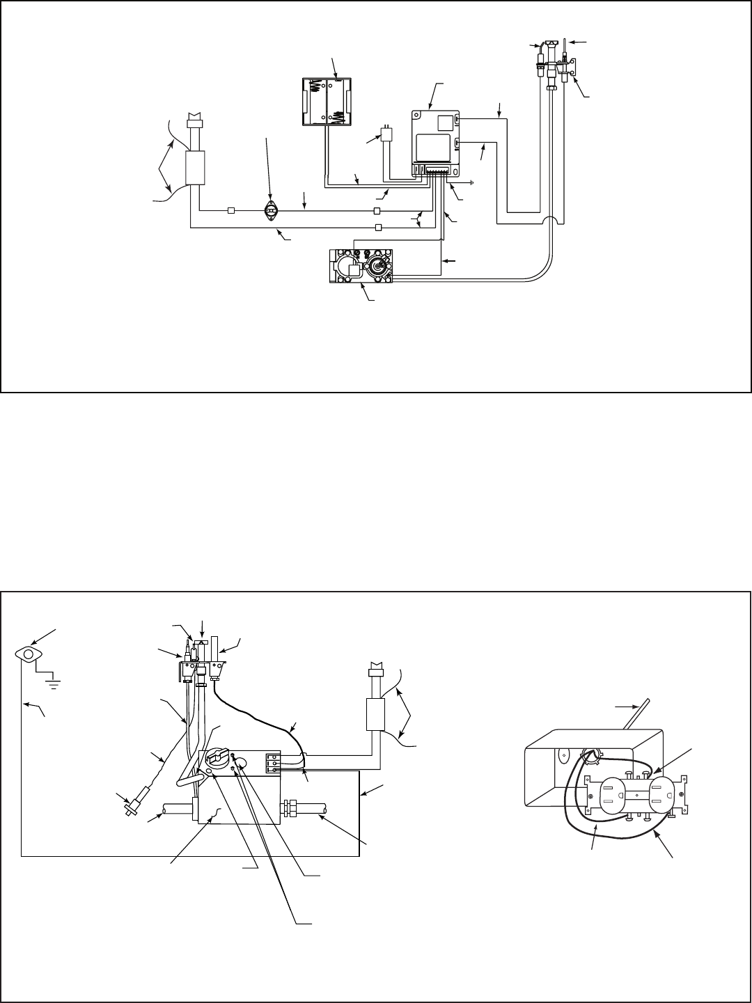
D. Standing Pilot Ignition System Wiring
• This standing pilot ignition system wiring does not require
a 110 VAC supply to operate. See Figure 10.3 for the
wiring diagram.
• It is recommended that a 110 VAC junction box be installed
for use with a fan or remote control. (See Figure 10.3 for
junction box wiring.)
Ignitor Flame
Sensor
Pilot
GRN
ORG
BLK
ORG
Control
Box
To
Junction
Box
Battery
Pack
3V
Adapter
BLK
BRN
RED
RED
BLK
Valve
High
Limit
Switch
WHT
WALL SWITCH
WHT
GRN*
*
GRN wire only used with
optional wall switch
WSK-MLT-HTL
BLU
Figure 10.2 Intellifi re Pilot Ignition (IPI) Wiring Diagram
PILOT
IGNITOR
VARIABLE
FLAME
ADJUSTMENT
PILOT
ADJUSTMENT
CAP
ROBERTSHAW GAS
VALVE MODEL 7000
TO BURNER
GAS INLET
HIGH
LIMIT
SWITCH
BLK
ORG
TAN
BLK
PUSH
BUTTON
IGNITOR
TO
PILOT
TH
TP
TH/TP
THERMOPILE
FLAME
SENSOR
COPPER
TUBING
WALL SWITCH
BRN
INLET & OUTLET
PRESSURE
TAPS
RED
WHT
GRN*
*GRN wire only used with
optional wall switch
WSK-MLT-HTL
Figure 10.3 Standing Pilot Ignition Wiring Diagram
Optional Accessories Requirements
Wiring for optional accessories should be done now to avoid
reconstruction.
BLACK
WHITE
GROUND
14-2 with
Ground Romex
Optional Junction Box Wiring
Heatilator • GB4336/GB4992 • 4003-085 Rev H • 04/06 23
E. Junction Box Installation
• Remove the junction box assembly from the valve
compartment.
• If the box is being wired from the OUTSIDE of the
appliance;
- Loosen two screws on the Romex connector, feed the
necessary length of wire through the connector and
tighten the screws.
- Make all necessary wire connections to the receptacle
and assemble the receptacle and cover to the junction
box.
- Attach the junction box assembly to the outside of the
appliance with the two screws provided.
• If the box is being wired from the INSIDE of the
appliance;
- Pull the electrical wires from outside the appliance
through this opening into the valve compartment.
- Loosen the two screws on the Romex connector, feed
the necessary length of wire through the connector and
tighten the screws.
- Make all necessary wire connections to the receptacle
and assemble the receptacle and cover to the junction
box.
- Attach the junction box assembly to the inside of the
appliance with the two screws provided.
• If the box is not to be wired at the time of appliance
installation, assemble the receptacle and cover to the box
and install on the inside of the appliance.
24 Heatilator • GB4336/GB4992 • 4003-085 Rev H • 04/06
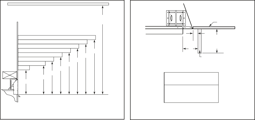
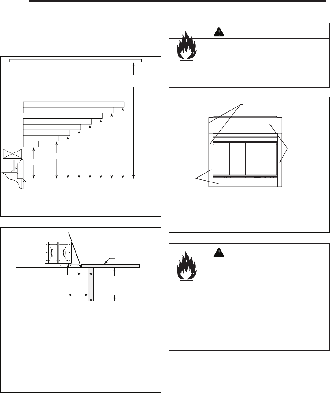
A. Mantel Projections
Figure 11.1 shows the minimum vertical and corresponding
maximum horizontal dimensions of appliance mantels or
other combustible projections above the top front edge of
the appliance.
B. Facing Material
Measured from top of hood (in inches)
3 - 12
13
14
15
16
17
18
13-1/4
14
14-3/4
15-1/2
16-1/4
17
17-3/4
30 in. minimum
to ceiling
0 - 3
9-3/8
Figure 11.1 Clearances to Mantels or other Combustibles above
Appliance.
1 in. (25mm) min.
to perpendicular wall
A
3-1/2 in. (89 mm) min.
from fireplace opening
to perpendicular wall
B
48 in.
(1219 mm)
max.
Mantel Leg or
Perpendicular Wall
Top o f
Appliance Drywall
A
B
Figure 11.2 Mantel Leg or Wall Projections
(Acceptable on both sides of opening)
High temperature sealant
These surfaces may
be covered with
noncombustible
material
These surfaces
may be
covered with
noncombustible
material
Figure 11.3 Noncombustible Facing Diagram
11
11 Finishing
Fire Risk
Finish all edges and fronts to clearances and
specifi cations listed in manual.
WARNING
• Black metal appliance front may be covered with non-
combustible material only.
• Do NOT overlap combustible materials onto appliance
front.
• Install combustible materials only up to specifi ed
clearances on top, front and sides.
• Seal joints between the fi nished wall and appliance
top and sides using only a 300° F minimum sealant.
Fire Risk
Do NOT obstruct air inlets.
Finishing materials must not interfere with:
• Air fl ow through inlets.
• Access for service.
WARNING
Heatilator • GB4336/GB4992 • 4003-085 Rev H • 04/06 25
A. Remove the Shipping Materials
Remove shipping materials from inside or underneath the
fi rebox.
Shock Risk
Fire Risk
Use ONLY optional accessories approved
for this appliance.
• Using non-listed accessories voids
warranty.
• Using non-listed accessories may result
in a safety hazard.
• Only Hearth & Home Technologies
approved accessories may be used
safely.
WARNING
Explosion Risk
• Follow rockwool placement instructions
in this manual.
• Do NOT place rockwool directly over
burner ports.
• Replace rockwool material annually.
Improperly placed rockwool interferes with
proper burner operation.
WARNING
12
12
Appliance Setup
B. Clean the Appliance
Clean/vacuum any sawdust that may have accumulated in-
side the fi rebox or underneath in the control cavity.
C. Accessories
Install approved accessories (refer to Section 16) per in-
structions included with accessories.
D. Install the Refractory
Install refractory per instructions included with kit.
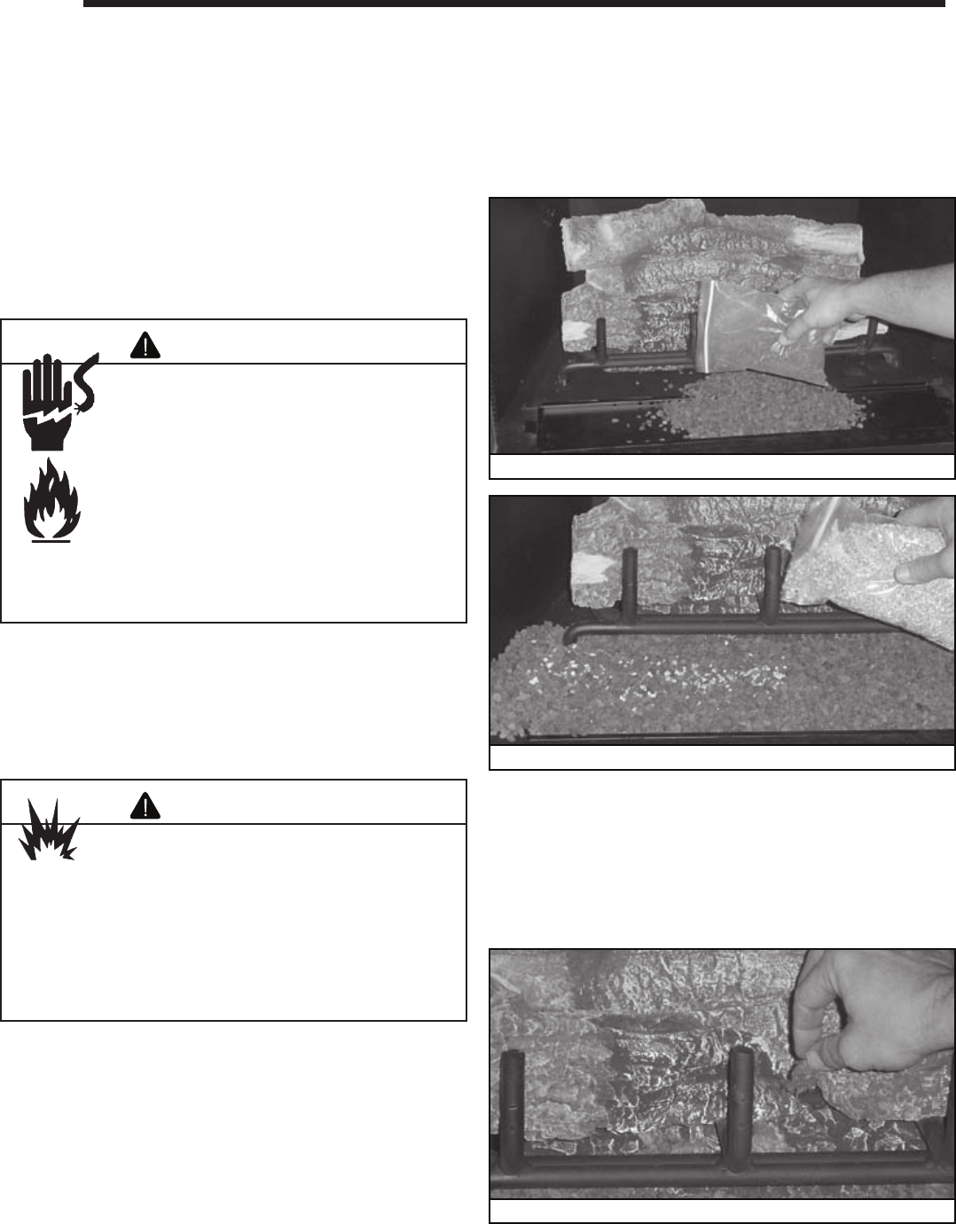
E. Lava Rock, Vermiculite, Rockwool Placement
Placing the Lava Rock and Vermiculite
• Place lava rock on top of the lava rock tray in front of and
under the burner. See Figure 12.1.
• Sprinkle vermiculite evenly over area covered by lava rock.
See Figure 12.2.
• It is not necessary to use entire bag of lava rock or
vermiculite.
Placing the Rockwool
• Place 1/2 in. pieces of rockwool under front logs and on
bottom hearth log.
• Place rockwool the full length of the burner., but not packed
against it. See Figure 12.3.
• It is not necessary to use all the rockwool.
Figure 12.1 Placement of Lava Rock
Figure 12.2 Placement of Vermiculite
Figure 12.3 Placement of Rockwool
26 Heatilator • GB4336/GB4992 • 4003-085 Rev H • 04/06
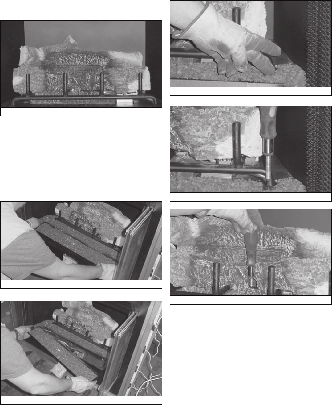
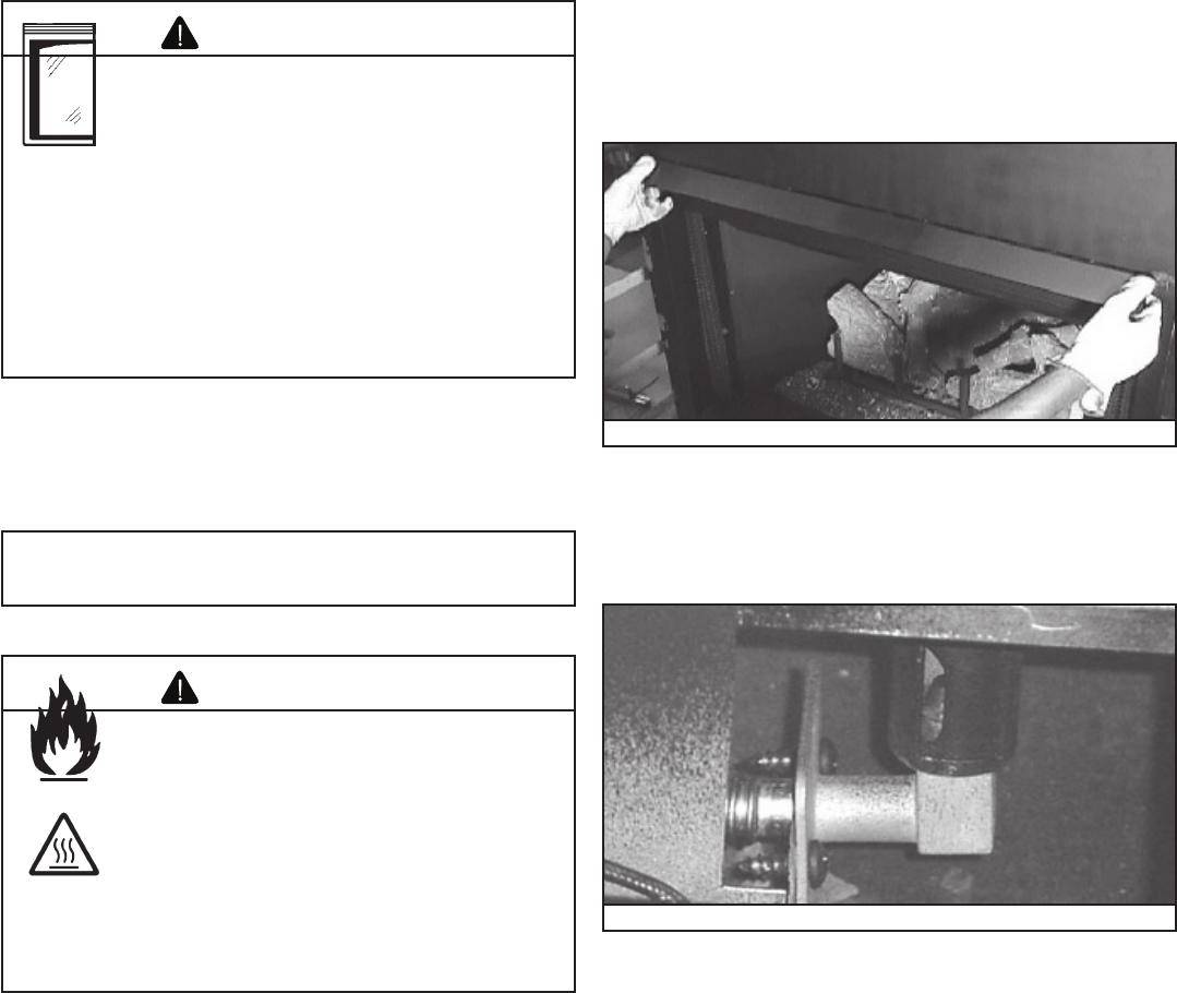
F. Log Removal/Replacement
Log set should look similar to that in Figure 12.4.
Figure 12.4 Geneva Log Set
• Remove/open the lava rock tray as shown in Figures 12.5
and 12.6. Clear the lava rock as shown in Figure 12.7.
• Remove log/grate assembly from the hearth pan by
removing three screws (one per side, one center back
behind hearth log). See Figures 12.8 and 12.9.
• Lift up on log/grate assembly to remove it from appliance
and set aside.
• Reverse the order to reinstall the log/grate assembly.
Figure 12.5 Remove Lava Rock Tray
Figure 12.6 Remove Lava Rock Tray
Figure 12.7 Clear Lava Rock
Figure 12.8 Remove Screws from Sides
Figure 12.9 Remove Screw from Back of Assembly
Heatilator • GB4336/GB4992 • 4003-085 Rev H • 04/06 27
Handle glass with care.
• Inspect the gasket to ensure it is
undamaged.
• Inspect the glass for cracks, chips or
scratches.
• Do NOT strike, slam or scratch glass.
• Do NOT operate appliance with glass
assembly removed, cracked, broken or
scratched.
• Replace glass assembly as a complete
assembly.
WARNING
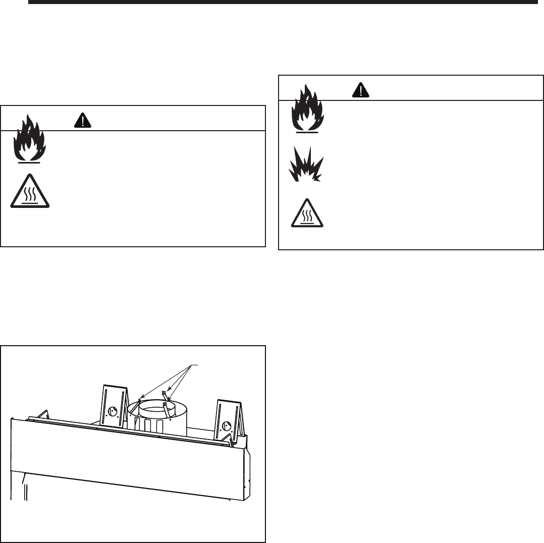
H. Hood
The hood is shipped on top of the outer shell of the appli-
ance. Remove the hood from its shipping location. Locate
the four hood retaining clips and slide the hood into them.
The hood must be attached or a fi re hazard may result. See
Figure 12.10.
Figure 12.10 Installing the Hood
G. Glass Doors
I. Air Shutter Setting
• Closed position - natural gas
• Open position - propane
Figure 12.11 Air Shutter
Note: Glass doors are not optional in the Commonwealth
of Massachusetts. They are required.
If you have decided to install optional doors on your appli-
ance, please use them correctly. While operating your appli-
ance, you should either have the doors completely open or
completely closed, but never partially open.
Fire Risk
Combustion Fumes Risk
• Appliances equipped with optional glass
doors must be operated with doors fully
open or fully closed.
• Only use glass doors certifi ed for use with
this appliance.
If doors are left partially open, gas and
fl ames may be drawn out of the appliance
opening.
WARNING
28 Heatilator • GB4336/GB4992 • 4003-085 Rev H • 04/06
A. Before Lighting Appliance
Before lighting this appliance, determine if it has a stand-
ing pilot or Intellifi re ignition system by opening the control
access panel to view wiring system and gas valve. If this
appliance has a red or black ignitor button (See Figure 10.1)
this appliance has a standing pilot ignition system. If there is
no red or black ignitor button, this appliance has an Intellifi re
ignition system.
If installing Intellifi re Ignition battery backup:
• Do not install batteries if the backup mode may
not be used for extended time.
• Batteries may leak.
• Install batteries only when needed for power
outage.
CAUTION Fire Risk
Burn Risk
HOT! DO NOT TOUCH.
SEVERE BURNS MAY RESULT.
CLOTHING IGNITION MAY RESULT
Glass and other surfaces are hot during
operation and cool down.
WARNING
• Keep children away.
• CAREFULLY SUPERVISE children in same room as
appliance.
• Alert children and adults to hazards of high
temperatures.
• Do NOT operate with protective barriers open or
removed.
• Keep clothing, furniture, draperies and other
combustibles away.
Improper installation, adjustment, alteration, service or
maintenance can cause injury or property damage. Refer
to the owner’s information manual provided with this
appliance. For assistance or additional information consult
a qualifi ed installer, service agency or the gas supplier.
WARNING
Do NOT use this appliance if any part has been under
water. Immediately call a qualifi ed service technician
to inspect the appliance and to replace any part of the
control system and any gas control which has been
under water.
WARNING
Before operating this appliance, have a qualifi ed
technician:
• Remove all shipping materials from inside and/or
underneath the fi rebox.
• Review proper placement of logs, rockwool, lava rock and
vermiculite.
• Check the wiring.
• Check the air shutter adjustment.
• Ensure that there are no gas leaks.
• Ensure that the glass doors are in the proper position.
• Ensure that the fl ow of combustion and ventilation air is
not obstructed (front grilles and vent caps).
13
13
Operating Instructions
Heatilator • GB4336/GB4992 • 4003-085 Rev H • 04/06 29
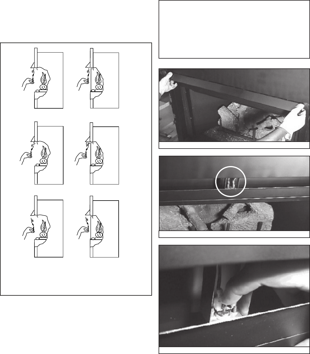
B. Check Appliance Draft
Check draft of appliance to verify proper venting conditions.
• Close all windows and doors, turn on all exhaust fans in
home.
• Appliance is to be completely assembled to normal
operating condition.
• Turn on appliance and allow to operate for at least 10
minutes.
• Check draft as shown in Figure 13.1. This can be done
using a smoke or fl ame producing match.
• Hold lit match at bottom edge of draft hood opening and
observe fl ame/smoke per the fi gure.
Without
doors.
With doors
closed.
Flame up-Acceptable
Flame in-Good
Flame out-Bad
Flame up-Acceptable
Flame in-Good
Flame out-Bad
Figure 13.1 Checking Appliance Draft
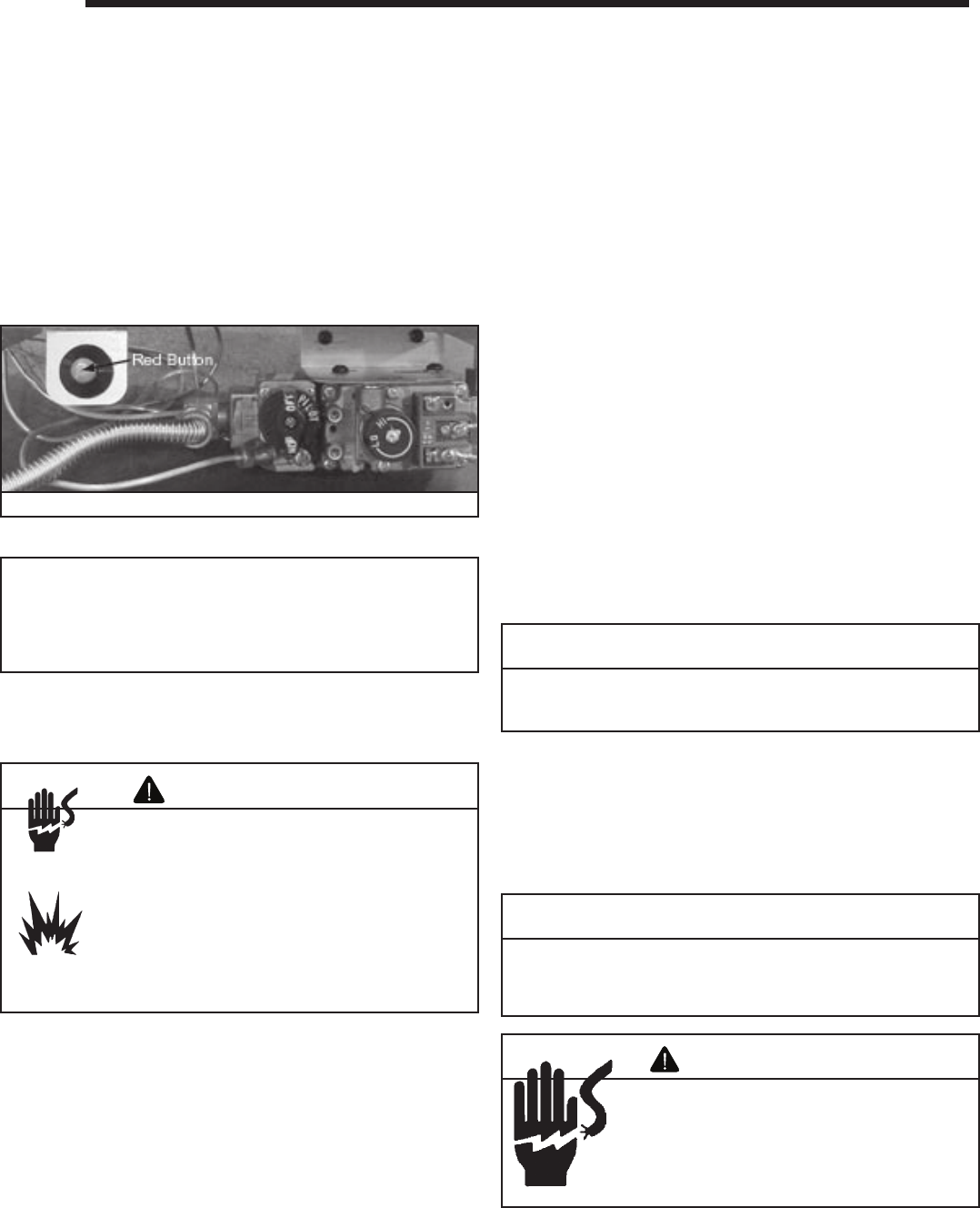
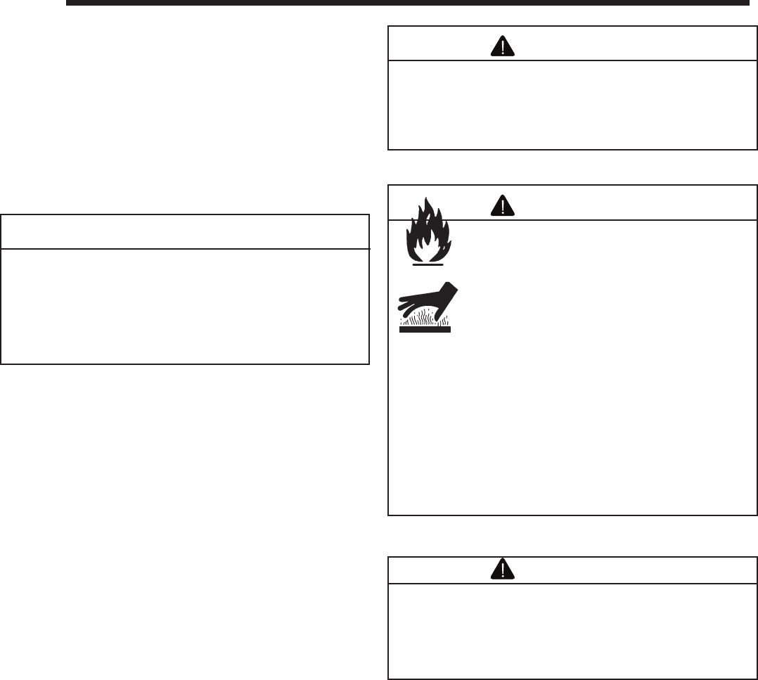
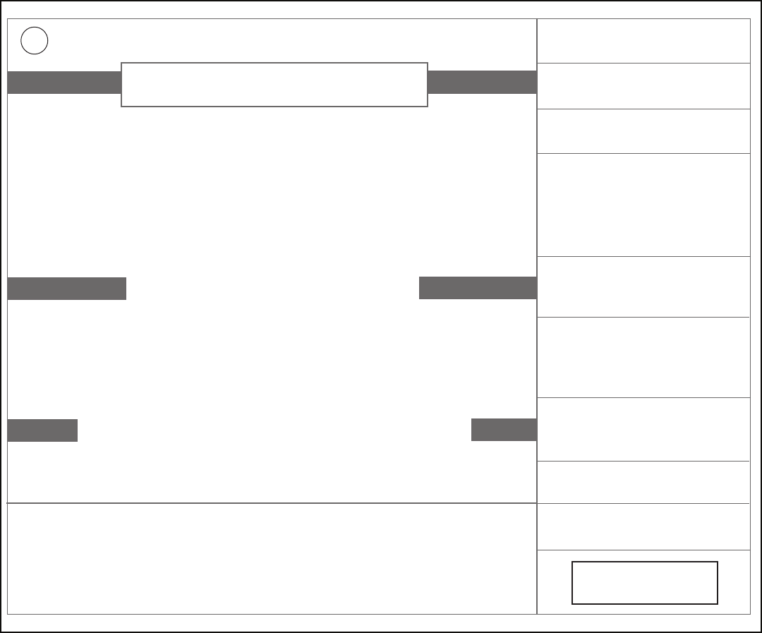
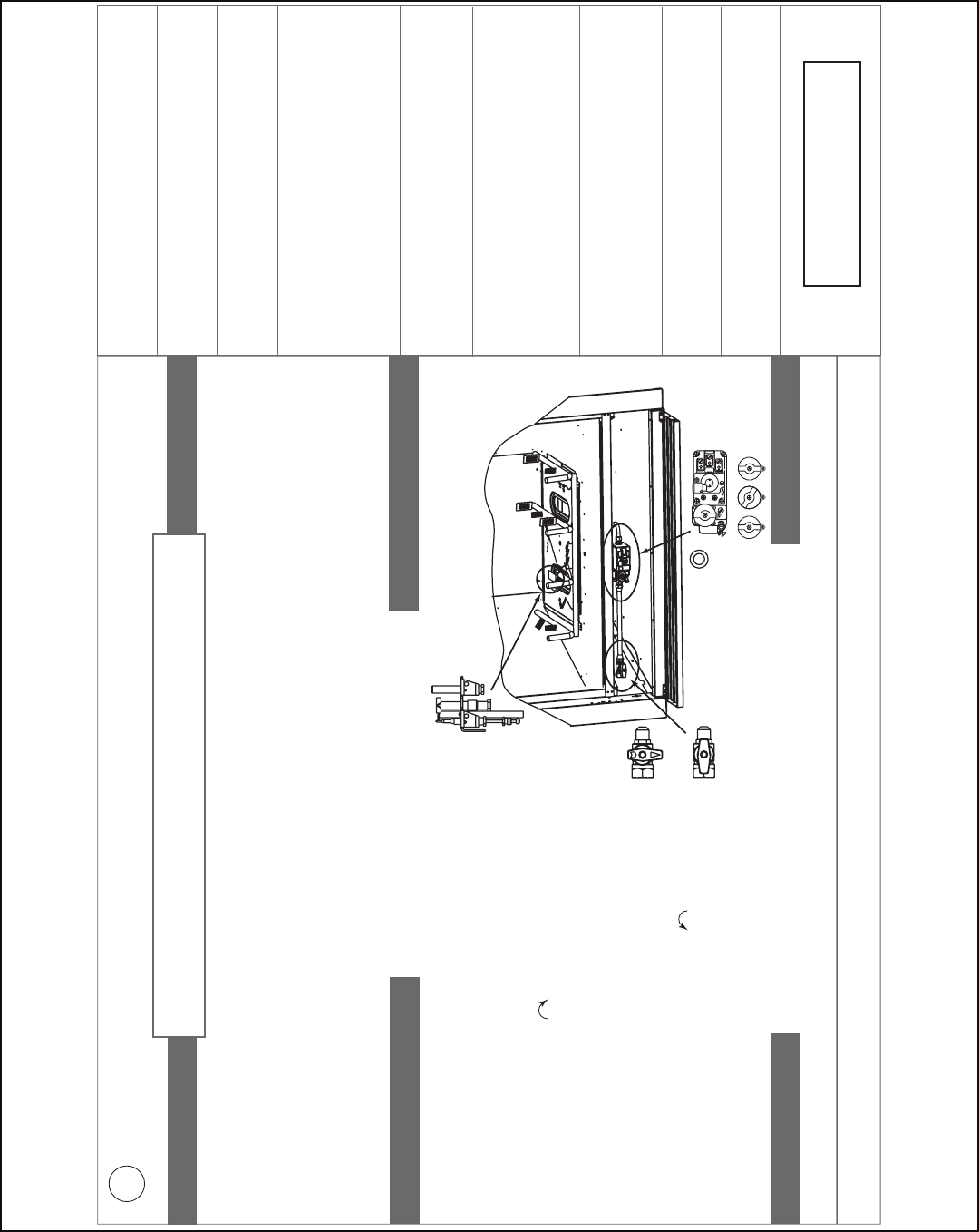
C. High Limit Safety Switch
A high limit switch has been installed on this appliance. This
switch automatically turns off the appliance if it becomes too
hot. If this happens, do not attempt to operate the appliance
until it has been examined by a qualifi ed service technician.
For the high limit switch location, see Figures 13.2-13.4.
Figure 13.2 Remove the Hood
Figure 13.5 Resetting the Limit Switch
Figure 13.4 Limit Switch Location
Note to Qualifi ed Service Technician:
The intermittent pilot ignition version of the Geneva Series
requires that the limit switch be manually reset if it has shut
the appliance off. This is done by fi rst removing the hood to
expose the high limit switch. See Figure 28. Push the red
button in until you hear a click. The appliance should now
be operable. Replace the hood.
30 Heatilator • GB4336/GB4992 • 4003-085 Rev H • 04/06
A. This appliance is equipped with an ignition device which
automatically lights the pilot. Do not try to light the pilot
by hand.
B. BEFORE LIGHTING smell all around the appliance area
for gas. Be sure to smell next to the floor because some
gas is heavier than air and will settle on the floor.
WHAT TO DO IF YOU SMELL GAS
• Do not try to light any appliance.
• Do not touch any electric switch; do not use any
phone in your building.
• Immediately call your gas supplier from a neighbor's
phone. Follow the gas supplier's instructions.
• If you cannot reach your gas supplier, call the fire
department.
LIGHTING INSTRUCTIONS
1. STOP! Read the safety information above on this label.
2. Turn wall switch to the "OFF" position or thermostat to
the lowest setting.
3. Turn off all electric power to the appliance.
4. This appliance is equipped with an ignition device which
automatically lights the pilot. Do NOT try to light the pilot
by hand.
5. Wait five minutes to clear out any gas. If you then smell gas,
STOP! Follow "B" in the safety information above on this label. If
you don't smell gas, go to the next step.
6. To turn on the burner, turn on all electric power to this appliance
and turn on the wall switch or set the thermostat to the desired
setting.
7. If the appliance will not operate, follow the instructions "TO TURN
OFF GAS TO APPLIANCE" and call your service technician or gas
supplier.
TO TURN OFF GAS TO APPLIANCE
1. Turn off wall switch or set thermostat to lowest setting.
2. Turn off all electric power to the appliance if service is to
be performed.
3. Push the gas control lever in and move to the "OFF"
position or push the gas control lever to the "OFF"
position. Do not force.
4. Replace the control access panel.
Due to high surface temperatures, keep children, clothing and furniture away.
Keep burner and control compartment clean. See installation and operating instructions accompanying the appliance.
WARNING: If you do not follow these instructions exactly, a
fire or explosion may result causing property
damage, personal injury or loss of life.
FOR YOUR SAFETY READ BEFORE LIGHTING
33631D
C. Use only your hand to push in and move the gas control
valve or turn the gas control knob. Never use tools. If the
lever or knob will not move by hand, don't try to repair it,
call a qualified service technician. Force or attempted
repair may result in a fire or explosion.
D. Do not use this appliance if any part has been under
water. Immediately call a qualified service technician to
inspect the appliance and to replace any part of the
control system and any gas control which has been
under water.
This appliance needs fresh air for safe operation and must
be installed so there are provisions for adequate
combustion and ventilation air.
This appliance must be installed in accordance
with local codes, if any; if not, follow ANSI
Z223.1 or, in Canada, current CAN/CGA-B149.
WARNING:
Improper installation,
adjustment, alteration, service or maintenance
can cause injury or property damage. Refer to
the owner's information manual provided with
the appliance. For assistance or additional
information consult a qualified installer, service
agency or the gas supplier.
CAUTION:
Hot while in operation. Do not touch.
Keep children, clothing, furniture, gasoline and other liquids
having flammable vapors away.
WARNING RISK OF FIRE
This appliance is intended to burn a specified gas fuel only. Do
not attempt to use with solid wood fuel or another type of fuel.
Do not attempt to modify or use any other type of gas burner
system.
* Also certified for installation in a bedroom or
a bed-sitting room.
* For U.S. only!
WARNING: Disconnect the electric power before
servicing. If for any reason the original wire supplied with the
appliance must be replaced, it must be replaced with 105° C or its
equivalent.
For use with natural gas or propane. A conversion
kit as supplied by the manufacturer shall be used
to convert this appliance to the alternative fuel.
This appliance must be properly connected to a
venting system in accordance with the
manufacturer's installation instructions.
NATURAL GAS
D. Lighting the Appliance
Intellifi re Ignition
Heatilator • GB4336/GB4992 • 4003-085 Rev H • 04/06 31
Standing Pilot Ignition
A. This appliance has a pilot which must be lighted by hand. When
lighting the pilot, follow these instructions exactly.
B. BEFORE LIGHTING smell all around the appliance area for gas.
Be sure to smell next to the floor because some gas is heavier
than air and will settle on the floor.
WHAT TO DO IF YOU SMELL GAS
• Do not try to light any appliance.
• Do not touch any electric switch; do not use any phone in your
building.
• Immediately call your gas supplier from a neighbor's phone.
Follow the gas supplier's instructions.
• If you cannot reach your gas supplier, call the fire department.
LIGHTING INSTRUCTIONS
1. Turn wall switch to the "OFF" position or thermostat to the
lowest setting.
2. Remove control access panel.
3. Turn manual gas valve to CLOSED. Wait five [5] minutes to
clear out any gas. If you then smell gas, STOP! Follow "B" in the
safety information above on this label. If you don't smell gas, go
to next step.
4. Turn gas line to "OPEN".
5. Turn pilot knob clockwise to "OFF". (Knob may have to be
depressed to pass "PILOT" position.)
6. Locate pilot assembly inside appliance.
7. Locate red ignitor button.
8. Turn pilot knob to "PILOT" and push in.
9. Continue to hold in pilot knob and push the red ignitor button
12-15 times until small blue pilot flame appears.
10. Continue to hold in pilot knob for approximately one minute. Pilot
should remain lit. If pilot goes out, wait 5 minutes and repeat
Steps 3-9.
11. Release and turn knob counterclockwise to "ON".
12. If appliance will not operate, follow the instructions "TO TURN
OFF GAS TO APPLIANCE" and call your service technician or
gas supplier.
NOTE: To light main burner, turn wall switch to "ON". Do not light by
hand.
TO TURN OFF GAS TO APPLIANCE
1. Turn off wall switch or set thermostat to lowest setting.
2. Remove control access panel.
3. Turn manual gas valve to "CLOSED position. Do not force.
4. Replace control access panel.
Due to high surface termperatures, keep children, clothing and furniture away.
Keep burner and control compartment clean. See installation and operating instructions accompanying the appliance.
WARNING: If you do not follow these instructions exactly, a fire or
explosion may result causing property damage, personal
injury or loss of life.
FOR YOUR SAFETY READ BEFORE LIGHTING
29097D
This appliance needs fresh air for safe operation
and must be installed so there are provisions for
adequate combustion and ventilation air.
This appliance must be installed in accordance with
local codes, if any; if not, follow ANSI Z223.1 or, in
Canada, current CAN/CGA-B149.
WARNING:
Improper installation,
adjustment, alteration, service or maintenance can
cause injury or property damage. Refer to the owner's
information manual provided with the appliance. For
assistance or additional information consult a
qualified installer, service agency or the gas supplier.
CAUTION:
Hot while in operation. Do not touch.
Keep children, clothing, furniture, gasoline and other liquids
having flammable vapors away.
WARNING RISK OF FIRE
This appliance is intended to burn a specified gas
fuel only. Do not attempt to use with solid wood fuel
or another type of fuel. Do not attempt to modify or
use any other type of gas burner system.
* Also certified for installation in a bedroom or a
bed-sitting room.
* For U.S. only!
C. Use only your hand to push in or turn knob. Never use tools. If
the manual gas valve will not push in or turn by hand, don't try
to repair it; call a qualified service technician. Force or
attempted repair may result in a fire or explosion.
D. Do not use this appliance if any part has been under water.
Immediately call a qualified service technician to inspect the
appliance and to replace any part of the control system and any
gas control which has been under water.
Stop! Read the safety information above on this label.
ON
OFF
PILOT
OFF
PILOT
ON
OFF
PILOT
5
ON
OFF
VENT
ON
7
5811
3. CLOSED
4. OPEN
WARNING:
Disconnect the electric power
before servicing. If for any reason the original wire
supplied with the appliance must be replaced, it must be
replaced with 105° C or its equivalent.
For use with natural gas or propane. A conversion
kit as supplied by the manufacturer shall be used to
convert this appliance to the alternative fuel.
This appliance must be properly connected to a
venting system in accordance with the
manufacturer's installation instructions.
NATURAL GAS
32 Heatilator • GB4336/GB4992 • 4003-085 Rev H • 04/06
Note: This appliance should be run three to four hours on
the initial start-up. Turn it off and let it cool completely. Clean
glass doors (if installed). Close the doors (if installed) and
run the appliance for an additional 12 hours. This will help
cure the products used in the paint and logs.
• Prevent accidental appliance operation when not
attended.
• Unplug or remove batteries from remote control in
your absence or if appliance will not be used for an
extended period of time.
• Property damage possible from elevated
temperatures.
CAUTION
Smoke and odors are released during initial
operation.
• Open windows for air circulation.
• Leave room during initial operation.
• Smoke may set off smoke detectors.
Smoke and odors may be irritating to sensitive
individuals.
CAUTION
Fire Risk
Keep combustible materials, gasoline and
other fl ammable vapors and liquids clear of
appliance.
• Do NOT store fl ammable materials in the
vicinity of the appliance.
• Do NOT use gasoline, lantern fuel,
kerosene, charcoal lighter fl uid or similar
liquids in this appliance.
Combustible materials may ignite.
WARNING
Fire Risk
High Temperatures
Keep combustible household items away
from appliance.
Do NOT obstruct combustion and ventilation
air.
• Do NOT place combustible items on top
of or in front of appliance.
• Keep furniture, draperies away from
appliance.
WARNING
F. Frequently Asked Questions
E. After the Appliance is Lit
Initial Break-in Procedure
When you light the appliance, you may notice that it pro-
duces heat which does have an associated odor or smell. If
you feel this odor is excessive it may require the initial three
to four hour continuous burn on high followed by a second
burn up to 12 hours to fully drive off any odor from paint and
lubricants used in the manufacturing process. Condensation
of the glass is normal.
During this break-in period it is recommended that some
windows in the house be opened for air circulation. This will
help avoid setting off smoke detectors, and help eliminate
any odors associated with the appliance’s initial burning.
Issue Solutions
Condensation on the glass This is a result of gas combustion and temperature variations. As the appliance warms, this condensation will
disappear.
Blue fl ames This is a result of normal operation and the fl ames will begin to yellow as the appliance is allowed to burn for 20 to
40 minutes.
Odor from appliance When fi rst operated, this appliance may release an odor for the fi rst several hours. This is caused by the curing of
the paint and the burning off of any oils remaining from manufacturing.
Film on the glass This is a normal result of the curing process of the paint and logs. Glass should be cleaned within 3 to 4 hours of
initial burning to remove deposits left by oils from the manufacturing process. A non-abrasive cleaner such as gas
fi replace glass cleaner may be necessary. See your dealer.
Metallic noise Noise is caused by metal expanding and contracting as it heats up and cools down, similar to the sound produced
by a furnace or heating duct. This noise does not affect the operation or longevity of the fi replace.
Is it normal to see the pilot
fl ame burn continually?
In an Intellifi re ignition system it is normal to see the pilot fl ame, but it should turn off when ON/OFF is turned off.
In a standing pilot system the pilot will always stay on.
Heatilator • GB4336/GB4992 • 4003-085 Rev H • 04/06 33
With proper installation, operation and maintenance your gas appliance will provide years of trouble-free service. If you do
experience a problem, this troubleshooting guide will assist a qualifi ed service person in the diagnosis of a problem and the
corrective action to be taken. This troubleshooting guide can only be used by a qualifi ed service technician.
A. Standing Pilot Ignition System
Symptom Possible Causes Corrective Actions
1. After repeated triggering
of the red or black piezo
ignitor button, the spark
ignitor will not light the
pilot.
A. Defective ignitor. Check the spark at the electrode and pilot. If there is no spark and the
electrode wire is properly connected, replace the ignitor.
B. Defective pilot or
misaligned electrode
(spark at electrode).
Using a match, light the pilot. If the pilot lights, turn off the pilot and trigger
the red piezo ignitor button again. If the pilot lights, an improper gas/air
mixture caused the bad lighting and a longer purge period is recommended.
If the pilot will not light, ensure the gap at the electrode and pilot is 1/8 in. to
have a strong spark. If the gap is OK, replace the pilot.
C. No gas or low gas
pressure.
Check the remote shut-off valves from the appliance. There is usually a
valve near the gas main. There can be more than one valve between the
appliance and the main.
D. No LP in tank. Check the LP (propane) tank. You may be out of fuel.
2. The pilot will not stay lit
after carefully following
the lighting instructions
A. Defective thermocouple. Check that the pilot fl ame impinges on the thermocouple. Clean and/or
adjust the pilot for maximum fl ame impingement.
Ensure that the thermocouple connection at the gas valve is fully inserted
and tight (hand tighten plus 1/4 turn).
Disconnect the thermocouple from the valve, place one millivolt meter lead
wire on the tip of the thermocouple and the other meter lead wire on the
thermocouple copper lead. Start the pilot and hold the valve knob in. If the
millivolt reading is less than 15mV, replace the thermocouple.
B. Defective valve. If the thermocouple is producing more than 15 millivolts, replace faulty valve.
3. The pilot is burning, there
is no gas burning, the
valve knob is in the ON
position, and the ON/
OFF switch is in the ON
position.
A. ON/OFF switch or wires
are defective.
Check the ON/OFF switch and wires for proper connections. Place the
jumper wires across the terminals at the switch. If the burner comes on,
replace the defective switch. If the switch is OK, place the jumper wires
across the switch wires at the gas valve. If the burner comes on, the wires
are faulty or connections are bad.
B. Thermopile may not be
generating suffi cient
millivoltage.
If the pilot fl ame is not close enough physically to the thermopile, adjust the
pilot fl ame.
Be sure the wire connections from the thermopile at the gas valve terminals
are tight and that the thermopile is fully inserted into the pilot bracket.
Check the thermopile with a millivolt meter. Take the reading at TH-TP&TP
terminals of the gas valve. The meter should read 325 millivolts minimum
while holding the valve knob depressed in the pilot position, with the pilot lit,
and the ON/OFF switch in the OFF position. Replace the faulty thermopile of
the reading is below the specifi ed minimum.
With the pilot in the ON position, disconnect the thermopile leads from
the valve. Take a reading at the thermopile leads. The reading should be
325 millivolts minimum. Replace the thermopile if the reading is below the
minimum.
C. Defective valve. Turn the valve knob to the ON position. Place the ON/OFF switch in the ON
position. Check the millivolt meter at the thermopile terminals. The millivolt
meter should read greater than 125mV. If the reading is acceptable, and if
the burner does not come on, replace the gas valve.
D. Plugged burner orifi ce. Check the burner orifi ce for stoppage. Remove stoppage.
E. Wall switch or wires are
defective.
Follow the corrective action in Symptom and Possible Cause 1.A. above.
Check the switch and wiring. Replace where defective.
14
14
Troubleshooting

34 Heatilator • GB4336/GB4992 • 4003-085 Rev H • 04/06
Symptom Possible Causes Corrective Actions
4. Frequent pilot outage
problem.
A. Pilot fl ame may be too
high, too low, or blowing
(high), causing pilot safety
to drop out.
Clean and adjust the pilot fl ame for maximum fl ame impingement on
thermocouple. Follow lighting instructions carefully.
5. The pilot and main
burner extinguish while in
operation.
A. No LP in the tank. Check the LP (propane) tank. Refi ll the fuel tank.
B. Inner vent pipe is leaking
exhaust gases back into
the system.
Check venting system for damage. Replace/repair improperly assembled
pipe sections.
C. Glass is too loose and
air tight packet leaks in
corners after usage.
Replace glass panel assembly.
D. Bad thermopile or
thermocouple.
Replace if necessary.
E. Improper vent cap
installation.
Check for proper installation and freedom from debris or blockage.
6. Glass soots. A. Flame impingement. Adjust the log set so that the fl ame does not excessively impinge on it.
B. Improper air shutter
setting.
Adjust the air shutter located on the control panel.
C. Debris around air shutter. Inspect the opening at the base of the burner. NO MATERIAL SHOULD BE
PLACED IN THIS OPENING.
7. Flame burns blue and lifts
off burner.
A. Insuffi cient oxygen being
supplied.
Ensure that the vent cap is installed properly and free of debris.
Ensure that the vent system joints are tight and have no leaks.
Ensure that no debris has been placed at the base of, or in the area of the
air holes in the center of, the base pan beneath the burner.
Ensure that the glass is tightened properly on the appliance, particularly on
top corners.

Heatilator • GB4336/GB4992 • 4003-085 Rev H • 04/06 35
B. Intellifi re Ignition System
Symptom Possible Causes Corrective Actions
1. The ignitor/module makes
noise, but no spark.
A. Incorrect wiring. Verify “S” wire (white) for sensor and “I” wire (orange) for ignitor are
connected to the correct terminals on the module and the pilot assembly.
Reversed wires at the module may cause the system to make a sparking
noise, but the spark may not be present at pilot hood.
B. Loose connections or
electrical shorts in the
wiring.
Verify there are no loose connections or electrical shorts in wiring from
module to pilot assembly. The rod closest to the pilot hood should be ignitor.
Verify connections underneath pilot assembly are tight; also verify the
connections are not grounding out to the metal chassis, pilot burner, pilot
enclosure, mesh screen if present, or any other metal object.
C. Ignitor gap is too large. Verify gap of ignitor to pilot hood. The gap should be approximately .17 in. or
1/8 in.
D. Faulty module. Turn ON/OFF rocker switch or wall switch to OFF position. Remove ignitor
wire “I” from module. Place ON/OFF rocker switch or wall switch in ON
position. Hold ground wire about 3/16 in. away from “I” terminal on module. If
there is no spark at “I” terminal, module must be replaced. If there is a spark
at “I” terminal, module is fi ne. Inspect pilot assembly for shorted sparker wire
or cracked insulator around electrode.
2. Pilots won’t light, there is
no noise or spark.
A. Transformer installed
incorrectly.
Verify that transformer is installed and plugged into module. Check voltage of
transformer under load at space connection on module with ON/OFF switch
in ON position. Acceptable readings of a good transformer are between 3.2
and 2.8 volts AC.
B. A shorted or loose
connection in wiring
confi guration or wiring
harness.
Remove and reinstall the wiring harness that plugs into module. Verify there is
a tight fi t. Verify pilot assembly wiring to module. Remove and verify continuity
of each wire in wiring harness.
C. Improper wall switch
wiring.
Verify wall switch is wired correctly.
D. Module not grounded. Verify black ground wire from module wire harness is grounded to metal
chassis of appliance.
E. Faulty module. Turn ON/OFF rocker switch or wall switch to OFF position. Remove ignitor
wire “I” from module. Place ON/OFF rocker switch or wall switch in ON
position. Hold ground wire about 3/16 in. away from “I” terminal on module. If
there is no spark at “I” terminal module must be replaced. If there is a spark at
“I” terminal, module is fi ne. Inspect pilot assembly for shorted sparker wire or
cracked insulator around electrode.
3. Pilot lights but continues
to spark, and main burner
will not ignite. (If the pilot
continues to spark after
the pilot fl ame has been
lit, fl ame rectifi cation has
not occurred.)
A. A shorted or loose
connection in sensor rod.
Verify all connections to wiring diagram in manual. Verify connections
underneath pilot assembly are tight. Verify connections are not grounding out
to metal chassis, pilot burner, pilot enclosure or screen if present, or any other
metal object.
B. Poor fl ame rectifi cation or
contaminated sensor rod.
Verify fl ame is engulfi ng sensor rod. If the pilot assembly does not have a
ground strap, consider installing one to increase fl ame rectifi cation. Verify
correct pilot orifi ce is installed and inlet gas specifi cations are met. Flame
carries rectifi cation current, not the gas. If fl ame lifts from pilot hood, the
circuit is broken. A wrong orifi ce or too high an inlet pressure can cause pilot
fl ame to lift. The sensor rod may be contaminated. Clean sensor rod with
emery cloth.
C. Module is not grounded. Verify that module is securely grounded to metal chassis of appliance. Verify
that the wire harness is fi rmly connected to module.
D. Damaged pilot assembly
or dirty sensor rod.
Verify that ceramic insulator around the sensor rod is not cracked, damaged,
or loose. Verify connection from sensor rod to white sensor wire. Clean
sensor rod with emery cloth to remove any contaminants that may have
accumulated on sensor rod. Verify continuity with a multimeter with ohms set
at lowest range.
E. Faulty module. Turn ON/OFF rocker switch or wall switch to OFF position. Remove ignitor
wire “I” from module. Place ON/OFF rocker switch or wall switch in ON
position. Hold ground wire about 3/16 in. away from “I” terminal on module. If
there is no spark at “I” terminal, module must be replaced. If there is a spark
at “I” terminal, module is fi ne. Inspect pilot assembly for shorted sparker wire
or cracked insulator around electrode.

36 Heatilator • GB4336/GB4992 • 4003-085 Rev H • 04/06
Symptom Possible Causes Corrective Actions
4. Pilot sparks, but pilot will
not light.
A. Correct gas supply. Verify that incoming gas line ball valve is “open”. Verify that inlet pressure
reading is within acceptable limits, inlet pressure must not exceed 14 in. w.c.
B. Ignitor gap is too large. Verify that spark gap from ignitor to pilot hood is .17 in. or 1/8 in.
C. Module is not grounded. Verify module is securely grounded to metal chassis of appliance.
D. Module voltage output/
valve/pilot solenoid ohms
readings.
Replace module.
Heatilator • GB4336/GB4992 • 4003-085 Rev H • 04/06 37
Although the frequency of appliance servicing and maintenance will depend on use and the type of installation, a qualifi ed
service technician should perform an appliance check-up at the beginning of each heating season.
Fire Risk
Explosion Risk
Inspect external vent cap regularly.
• Ensure no debris blocks cap.
• Combustible materials blocking cap may
ignite.
• Restricted air flow affects burner
operation.
WARNING
Annual inspection by qualified technician
recommended.
Check:
• Condition of doors, surrounds and fronts.
• Condition of glass, glass assembly and glass
seal.
• Obstructions of combustion and ventilation
air.
• Condition of logs.
• Condition of fi rebox.
• Burner ignition and operation.
• Burner air shutter adjustment.
• Gas connections and fi ttings.
• Obstructions of termination cap.
Clean:
• Glass.
• Air passageways, grilles, control
compartment.
• Burner, burner ports.
Risk of:
• Fire
• Delayed ignition or explosion
• Exposure to combustion fumes
• Odors
WARNING
Handle glass assembly with care.
Note: Clean glass after initial 3-4 hours
operation. Longer operation without
cleaning glass may cause a permanent
white fi lm on glass.
When cleaning glass door:
• Avoid striking, scratching or slamming
doors.
• Do NOT use abrasive cleaners.
• Use a hard water deposit glass cleaner on
white fi lm.
• Do NOT clean glass when it is hot.
• Turn off appliance after 3-4 hours of
operation and ALLOW TO COOL.
• Remove and clean glass assembly.
• Replace glass assembly and operate
appliance for an additional 12 hours.
Refer to maintenance instructions.
CAUTION
15
15
Maintaining and Servicing the Appliance
Risk of injury or property damage
Before servicing:
• Turn off gas.
• Turn off electricity to appliance.
• Disable remote control, if one is present.
• Ensure appliance is completely cooled.
After Servicing:
• Replace any screen or barrier that was removed.
• Reseal and reinstall any venting removed for
servicing.
WARNING

38 Heatilator • GB4336/GB4992 • 4003-085 Rev H • 04/06
Inspect Maintenance Tasks
Doors, surrounds and fronts 1. Assess condition of screen and replace as necessary. Recommend addition of screen if
one is not present.
2. Inspect for scratches, dents or other damage and repair as necessary.
3. Verify no obstructions to airfl ow through the louvers.
4. Verify proper clearance to combustible household objects is maintained.
Gasket seal, glass assembly and glass 1. Inspect gasket seal and its condition.
2. Inspect glass panels for scratches and nicks that can lead to breakage when exposed to heat.
3. Confi rm there is no damage to glass or glass frame. Replace as necessary.
4. Verify that latches engage properly, clip studs are not stripped, and glass attachment
components are intact and operating properly. Replace as necessary.
5. Clean glass using a nonabrasive cleaner such as Brasso®. Replace glass assembly if
severely coated with silicate deposits that cannot be removed.
Valve compartment and fi rebox top 1. Vacuum and wipe out dust, cobwebs, debris or pet hair. Use caution when cleaning these
areas. Screw tips that have penetrated the sheet metal are sharp and should be avoided.
2. Remove any foreign objects.
3. Verify unobstructed air circulation.
Logs 1. Inspect for broken, damaged, or missing logs. Replace as necessary.
2. Verify correct log placement and no fl ame impingement causing sooting. Correct as
necessary.
Firebox 1. Inspect for paint condition, warpage, corrosion or perforation. Sand and repaint as necessary.
2. Replace appliance if fi rebox has been perforated.
Burner ignition and operation 1. Verify burner is properly secured and aligned with pilot or ignitor.
2. Clean off burner top, inspect for plugged ports, corrosion or deterioration. Replace burner if
necessary.
3. Replace rockwool with new dime-sized and shaped pieces. Do not block ports or obstruct
lighting paths.
4. Check for smooth lighting and ignition carryover to all ports. Verify there is no ignition delay.
5. Inspect for lifting or other fl ame problems.
6. Verify air shutter is clear of dust and debris.
7. Inspect orifi ce for soot, dirt or corrosion.
8. Verify manifold and inlet pressures. Adjust regulator as required.
9. Inspect pilot fl ame strength. Clean or replace orifi ce as necessary.
10. Inspect thermocouple/thermopile or IPI sensor rod for soot, corrosion and deterioration. Clean
with emery cloth or replace as required.
11. Verify millivolt output. Replace as necessary.
Venting 1. Inspect venting for blockage or obstruction such as birds’ nests, leaves, etc.
2. Confi rm that termination cap remains clear and unobstructed by plants, etc.
3. Verify that termination cap clearance to subsequent construction (building additions, decks,
fences or sheds) has been maintained.
4. Inspect for corrosion or separation.
5. Verify weather stripping sealing and fl ashing remain intact.
6. Inspect draft shield to verify it is not bent, damaged or missing.
Remote controls 1. Verify operation of remote.
2. Replace batteries in remote transmitters and battery-powered receivers.
3. Verify batteries have been removed from battery back-up in IPI systems to prevent premature
battery failure or leaking.
Maintenance and Service Tasks:
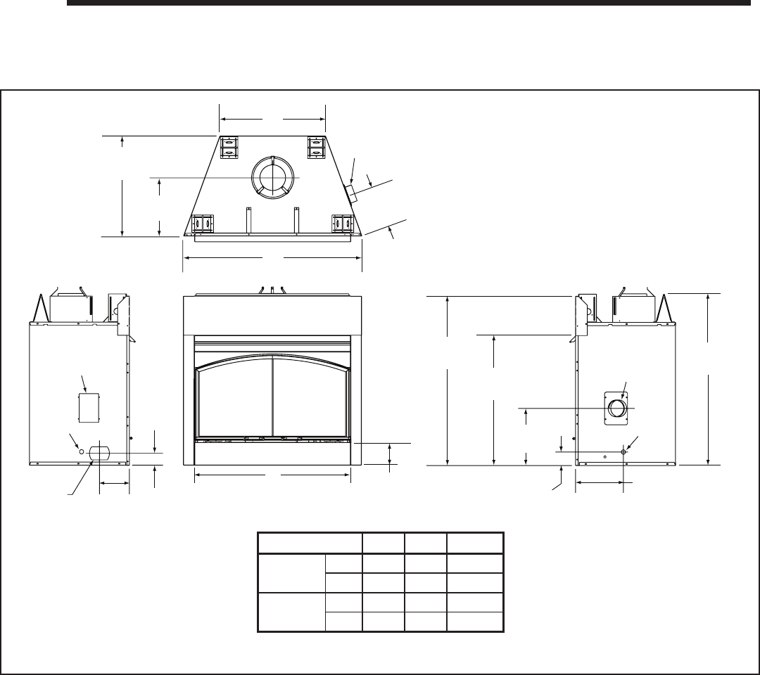
Heatilator • GB4336/GB4992 • 4003-085 Rev H • 04/06 39
A. Appliance Dimension Diagram
Dimensions are actual appliance dimensions. Use for reference only. For framing dimensions and clearances refer to Sec-
tion 3.
Figure 16.1 Appliance Dimensions
16
16 Reference Materials
B4-3/8 in.
(111 mm)
Outside Air
13-1/4 in.
(337 mm)
3-1/8 in.
(79 mm)
11-1/8 in.
(283 mm)
Outside Air
Gas
Access
Electric
Access
2-3/4 in.
(70 mm)
7 in.
(178 mm)
23-1/8 in.
(587 mm)
13-1/4 in.
(336 mm)
10 in.
(254 mm)
A
C
Outside
Air
39-1/8 in.
(994 mm) 39-1/2 in.
(1003 mm)
Alternative
Gas Access
30 in.
(762mm)
Model A B C
GB4336 in. 41 in. 36 in. 24-3/8 in.
mm 1041 914 619
GB4942 in. 47 in. 42 in. 30-3/8 in.
mm 1194 1067 772
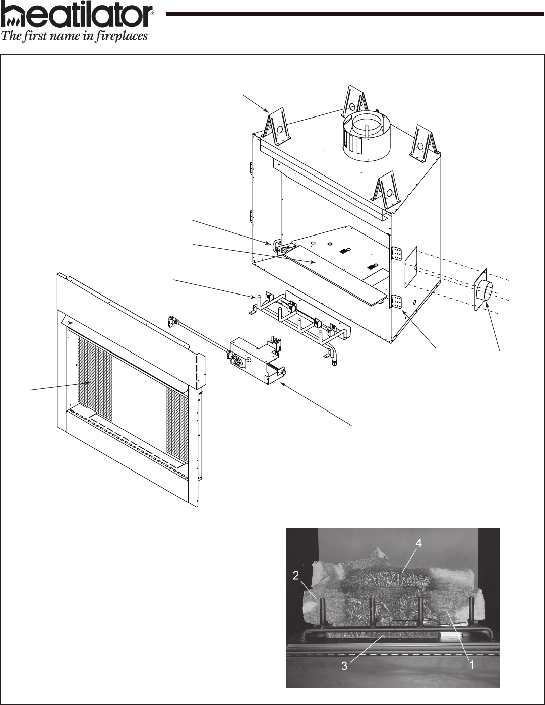
40 Heatilator • GB4336/GB4992 • 4003-085 Rev H • 04/06
B. Service Parts List
Exploded Parts Diagram
36 in. Geneva Gas Fireplace
Service Parts GB4336 SERIES
Beginning Manufacturing Date: 1/19/04
Ending Manufacturing Date: Active
11
8
(Valve Assembly)
6
7
(Grate Assembly)
5
10
9
Heatilator • GB4336/GB4992 • 4003-085 Rev H • 04/06 41
Service Parts List
36 in. Geneva Gas Fireplace
Service Parts GB4336 SERIES
Beginning Manufacturing Date: 1/19/04
Ending Manufacturing Date: Active
Service Parts List
36 in. Geneva Gas Fireplace
Service Parts GB4336 SERIES
Beginning Manufacturing Date: 1/19/04
Ending Manufacturing Date: Active
# Description of Part GB4336 GB4336L GB4336I GB4336IL Qty.
Log/Grate Assembly 4003-072 4003-072 4003-072 4003-072 1
1 Right Log 4003-115 4003-115 4003-115 4003-115 1
2 Left Log 4003-116 4003-116 4003-116 4003-116 1
3 Hearth Log 4003-114 4003-114 4003-114 4003-114 1
4 Back Log 4003-117 4003-117 4003-117 4003-117 1
Wool, Rock, Vermiculite 30833 30833 30833 30833 1
Mineral Wool 14333B 14333B 14333B 14333B 1
Vermiculite 28746 28746 28746 28746 1
Lava Rock (2lb. Bag) 4021-296 4021-296 4021-296 4021-296 2
Ember Tray 4003-091 4003-091 4003-091 4003-091 1
5 Air Kit 26866 26866 26866 26866 1
Fastener Pack 17916B 17916B 17916B 17916B 1
Long Cable Tie 19954A 19954A 19954A 19954A 2
Outside Air Shield 33271 33271 33271 33271 1
Air Kit Installation Instructions 35145 35145 35145 35145 1
Face Assembly
Hair Pin Clip 101025 101025 101025 101025 2
Door Track 15425 15425 15425 15425
Door Pivot Clip 31527 31527 31527 31527 2
6 Hood 29575 29575 29575 29575 1
7 Firescreen Assembly 32734 32734 32734 32734 2
Firescreen Ring 11857B 11857B 11857B 11857B 4
Screen Panel 24737 24737 24737 24737 1
Screen Handle 4021-150 4021-150 4021-150 4021-150 1
Top Air Defl ector 33197 33197 33197 33197 1
8 Nailing Flange 31190 31190 31190 31190 4
Junction Box Kit 31581 31581 31581 31581 1
9 Junction Box 21878 21878 21878 21878 1
Romex Connector 32536 32536 32536 32536 1
10 Gas Access Panel 31636 31636 31636 31636 2
11 Top Standoff 11864i 11864i 11864i 11864i 4
Geneva Pack 4003-122 4003-122 4003-126 4003-126 1
Outside Air Handle 17333 17333 17333 17333 1
Fastener Pack 35477 35477 35477 35477 1
Installation Instructions 4003-085 4003-085 4003-085 4003-085 1
Gas Operations Manual 71680 71680 71680 71680 1
Battery Pack 593-594A 593-594A 1
Back Baffl e 13961 13961 13961 13961 1
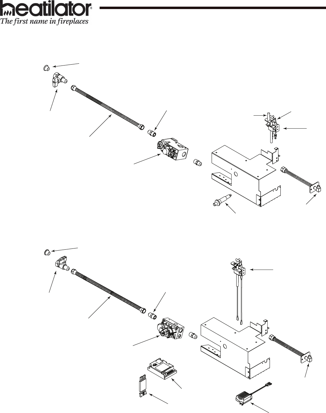
42 Heatilator • GB4336/GB4992 • 4003-085 Rev H • 04/06
Service Parts List
36 in. Geneva Gas Fireplace
Service Parts GB4336 SERIES
Beginning Manufacturing Date: 1/19/04
Ending Manufacturing Date: Active
10 9
8
2
1
4
6
3
7
Standing Pilot Valve Assembly
5
7
3
6
4
1
12
14
13
11
Intermittent Pilot Valve Assembly
5
Heatilator • GB4336/GB4992 • 4003-085 Rev H • 04/06 43
Service Parts List
36 in. Geneva Gas Fireplace
Service Parts GB4336 SERIES
Beginning Manufacturing Date: 1/19/04
Ending Manufacturing Date: Active
# Description of Part GB4336 GB4336L GB4336I GB4336IL Qty.
Valve Assembly 4003-103 4003-104 4003-105 4003-106 1
1 Valve 24033 24034 750-500 750-501 1
2 Push Button Ignitor 13416 13416 1
Cord Clip 14218 14218 14218 14218 1
3 ON/OFF Valve 15697 15697 15697 15697 1
4 Brass Connector - Male - Flex 17069 17069 17069 17069 2
5 Flex Bulkhead 4021-086 4021-086 4021-086 4021-086 1
6 16 in. Stainless Steel Flex Gas Line 17245B 17245B 17245B 17245B 1
Long Cable Tie 19954A 19954A 19954A 19954A 1
7 Dust Cap 23491 23491 23491 23491 1
C-Style Orifi ce (#35) - NG 582-835 582-835 1
C-Style Orifi ce (#52) - LP 582-852 582-852 1
High Limit Switch 33492 33492 24672 24672 1
8 Pilot Assembly - Flex Tube 25660 25661 1
9 Pilot 4021-005 4021-006 1
10 Thermocouple 72956 72956 1
11 Thermopile 060-512 060-512 1
12 Ignition Control Module *must order Velcro Strips* 593-592 593-592 1
Velcro Strips 17439A,17440A 17439A,17440A 1ea
13 3V Transformer 593-593A 593-593A 1
Battery Pack 593-594A 593-594A 1
Wall Switch Wire Assembly 28602 28602 4018-018 4018-018 1
HIBLK60FM Wire Assembly 34937 34937 1
HIBLK67FP Wire Assembly 32347 32347 1
HIBLU60FF 4018-019 4018-019 1
14 Wire Assembly 593-590A 593-590A 1
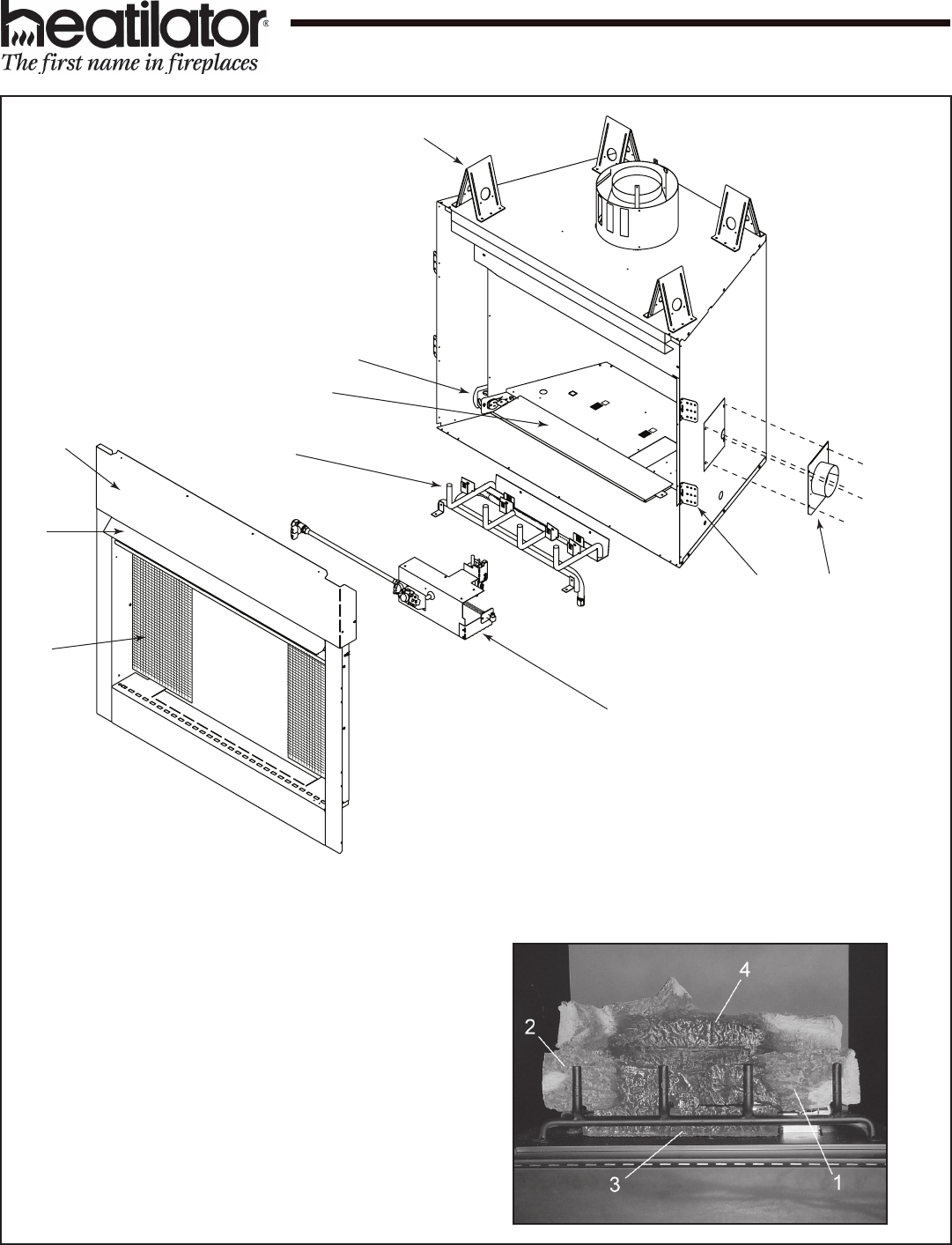
44 Heatilator • GB4336/GB4992 • 4003-085 Rev H • 04/06
Exploded Parts Diagram
42 in. Geneva Gas Fireplace
Service Parts GB4942 SERIES
Beginning Manufacturing Date: 1/19/04
Ending Manufacturing Date: Active
12
6
8
7
10
5
9
(Valve Assembly)
(Grate Assembly)
11
Heatilator • GB4336/GB4992 • 4003-085 Rev H • 04/06 45
Service Parts List
42 in. Geneva Gas Fireplace
Service Parts GB4942 SERIES
Beginning Manufacturing Date: 1/19/04
Ending Manufacturing Date: Active
# Description of Part GB4942 GB4942L GB4942I GB4942IL Qty.
Log/Grate Assembly 4003-073 4003-073 4003-073 4003-073 1
1 Right Log 4003-118 4003-118 4003-118 4003-118 1
2 Left Log 4003-119 4003-119 4003-119 4003-119 1
3 Hearth Log 4003-114 4003-114 4003-114 4003-114 1
4 Back Log 4003-120 4003-120 4003-120 4003-120 1
5 Air Kit 26866 26866 26866 26866 1
Fastener Pack 17916B 17916B 17916B 17916B 1
Long Cable Tie 19954A 19954A 19954A 19954A 2
Outside Air Shield 33271 33271 33271 33271 1
Air Kit Installation Instructions 35145 35145 35145 35145 1
Wool, Rock, Vermiculite 30833 30833 30833 30833 1
Mineral Wool 14333B 14333B 14333B 14333B 2
Vermiculite 28746 28746 28746 28746 1
Lava Rock (2lb. Bag) 4021-296 4021-296 4021-296 4021-296 2
Ember Tray 4003-092 4003-092 4003-092 4003-092 1
Face Assembly
Hairpin Clip 101025 101025 101025 101025 2
6 Hood 29576 29576 29576 29576 1
Door Pivot Clip 31527 31527 31527 31527 2
7 Firescreen Assembly 32734 32734 32734 32734 2
Firescreen Ring 11857B 11857B 11857B 11857B 4
Screen Panel 24737 24737 24737 24737 1
Screen Handle 4021-150 4021-150 4021-150 4021-150 1
8 Top Front 32818 32818 32818 32818 1
Top Air Defl ector 33198 33198 33198 33198 1
9 Nailing Flange 31190 31190 31190 31190 4
10 Junction Box Kit 31581 31581 31581 31581 1
Junction Box 21878 21878 21878 21878 1
Romex Connector 32536 32536 32536 32536 1
11 Gas Access Panel 31636 31636 31636 31636 2
12 Top Standoffs 11864i 11864i 11864i 11864i 4
Back Baffl e 13961 13961 13961 13961 1
Geneva Pack 4003-127 4003-127 1
Outside Air Handle 17333 17333 17333 17333 1
Fastener Pack 35477 35477 35477 35477 1
Geneva Installation Instructions 4003-085 4003-085 4003-085 4003-085 1
Gas Operations Manual 71680 71680 71680 71680 1
Battery Pack 593-594A 593-594A 1
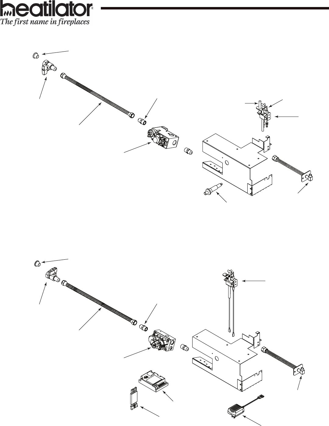
46 Heatilator • GB4336/GB4992 • 4003-085 Rev H • 04/06
Service Parts List
42 in. Geneva Gas Fireplace
Service Parts GB4942 SERIES
Beginning Manufacturing Date: 1/19/04
Ending Manufacturing Date: Active
10 9
8
2
1
4
6
3
7
Standing Pilot Valve Assembly
5
7
3
6
4
1
12
14
13
11
Intermittent Pilot Valve Assembly
5

Heatilator • GB4336/GB4992 • 4003-085 Rev H • 04/06 47
Service Parts List
42 in. Geneva Gas Fireplace
Service Parts GB4942 SERIES
Beginning Manufacturing Date: 1/19/04
Ending Manufacturing Date: Active
# Description of Part GB4942 GB4942L GB4942I GB4942IL Qty.
Valve Assembly 4003-103 4003-104 4003-105 4003-106 1
1 Valve 24033 24034 750-500 750-501 1
2 Push Button Ignitor 13416 13416 13416 13416 1
Cord Clip 14218 14218 14218 14218 1
3 ON/OFF Valve 15697 15697 15697 15697 1
4 Brass Connector - Male - Flex 17069 17069 17069 17069 2
5 Flex Bulkhead 4021-086 4021-086 4021-086 4021-086 1
6 16 in. Stainless Steel Flex Gas Line 17245B 17245B 17245B 17245B 1
Long Cable Tie 19954A 19954A 19954A 19954A 1
7 Dust Cap 23491 23491 23491 23491 1
8 Pilot Assembly 25660 25661 1
9 Thermocouple 72956 72956 1
10 Thermopile 060-512 060-512 1
11 Pilot 4021-005 4021-006 1
12 Ignition Control Module *must order Velcro Strips* 593-592 593-592 1
Velcro Strips 17439A,17440A 17439A,17440A 1ea
13 3V Transformer 593-593A 593-593A 1
Battery Pack 593-594A 593-594A 1
Wall Switch Wire Assembly 28602 28602 4018-018 4018-018 1
HIBLK67FP Wire Assembly 32347 32347 1
HIBLK60FM Wire Assembly 34937 34937 1
HIBLU60FF Wrie Assembly 4018-019 4018-019 1
14 Wire Assembly 593-590A 593-590A 1
C-Style Orifi ce (#32) - NG 582-832 582-832 1
C-Style Orifi ce (#51) - LP 582-851 582-851 1
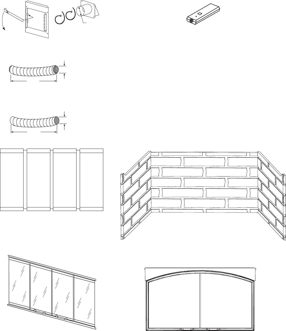
48 Heatilator • GB4336/GB4992 • 4003-085 Rev H • 04/06
C. Optional Components
AK14 - Air Kit
RC-SMART-HTL
Remote Control
RCT-MLT-HLT
Multifunctional Remote
RC-BATT-HTL
Battery Operated Remote Control
(Standing Pilot)
SMART-STAT-HTL
Remote control with Thermostat Control
SMART-BATT-HTL
Battery-operated Remote Control
with Thermostat Control
4 in.
*
DMA1036B
DMA1042B
Arched Door
DF361B/S
DF421B/S
Fixed Glass Doors
ID4 Insulated Duct
UD4 Uninsulated Duct
42 in.
(1067 mm)
4 in. (102 mm
)
42 in.
(1067 mm)
4 in. (102 mm
)
HB60G TB60G
HB80G TB80G
Traditional Brick Pattern (TB - shown)
Herringbone Pattern (HB)
Refractory
DM1036, DM1036B, DM1036S
DM1042, DM1042B, DM1042S
Bifold Doors
Heatilator • GB4336/GB4992 • 4003-085 Rev H • 04/06 49
This page intentionally left blank.
50 Heatilator • GB4336/GB4992 • 4003-085 Rev H • 04/06
This page intentionally left blank.

Heatilator • GB4336/GB4992 • 4003-085 Rev H • 04/06 51
Gas Appliance (Fireplace)
Limited Lifetime Warranty
HEARTH & HOME TECHNOLOGIES INC. (“HHT”) extends the following warranty for HEATILATOR® gas
appliances installed in the United States of America or Canada (the "Appliance"). Dealers and employees of HHT
have no authority to make any warranty or authorize any remedies in addition to or inconsistent with the terms of
this warranty.
Limited Lifetime Warranty
HHT warrants the Appliance for component failure due to a manufacturing defect of any of the following components: combustion chamber,
burner pan, and logs. The Limited Lifetime Warranty specifi ed above is subject to the conditions, exclusions and limitations listed below, is for
the period the Appliance is owned by the original homeowner only, and is nontransferable.
1 Year Limited Warranty
HHT warrants the Appliance to be free from failure of any of the following components for a period of one year after installation: valve, fl exible
gas line connector, glass panel, fan, direct vent chimney components, factory paint, gasket, piezo ignitor, thermopile, thermocouple, junction
box, pilot assembly, shutoff valve, high limit switch, refractory liners, transformer, and control box. If the Heatilator Appliance is found to be
defective in either material or workmanship within one year of the date of original installation, HHT will provide replacement parts at no charge
and pay reasonable labor and freight costs, and is for the period of one year following the date of original installation of the Appliance.
Conditions, Exclusions, & Limitations of Liability
A. Both the Limited Lifetime and 1 Year Limited Warranties supplied by HHT apply only while the Appliance is in its location of original
installation. HHT’s obligation under this warranty does not extend to damages resulting from (1) installation, operation or maintenance
of the Appliance not in accordance with the Installation Instructions, Operating Instructions, and the Listing Agent Identifi cation Label
furnished with the Appliance; (2) installation which does not comply with local building codes; (3) shipping, improper handling, improper
operation, abuse, misuse, accident or unworkmanlike repairs; (4) environmental conditions, inadequate ventilation or drafting caused by
tight sealing construction of the structure, air handling devices such as exhaust fans or forced air furnaces, or other causes; (5) use of
fuels other than those specifi ed in the Operating Instructions; (6) installation or use of components not supplied with the Appliance or any
other components not expressly authorized and approved by HHT; and/or (7) modifi cation of the Appliance not expressly authorized and
approved by HHT in writing. This warranty is limited to only the component parts manufactured or supplied by HHT.
B. HHT’s liability under both the Limited Lifetime Warranty and the 1 Year Limited Warranty is limited to the replacement and repair of
defective components or workmanship during the applicable period. HHT may fully discharge all of its obligations under such warranties
by repairing the defective component(s) or at HHT’s discretion, providing replacement parts at no charge and paying reasonable labor
and freight costs.
C. EXCEPT TO THE EXTENT PROVIDED BY LAW, HHT MAKES NO EXPRESS WARRANTIES OTHER THAN THE WARRANTY
SPECIFIED HEREIN. THE DURATION OF ANY IMPLIED WARRANTY IS LIMITED TO DURATION OF THE WARRANTY SPECIFIED
ABOVE.
D. Some states do not allow exclusions or limitations of incidental or consequential damages, so those limitations may not apply to you.
This warranty gives you specifi c rights; you may also have other rights which vary from state to state.
How to Obtain Service
To obtain service under this warranty you must:
1. Send written notice of the claimed condition to Heatilator Technical Service Department, Hearth & Home Technologies, 1915 W.
Saunders Street, Mt. Pleasant, Iowa 52641-1563. You may also register your claim online at www.heatilator.com.
2. Provide proof of purchase, model number, serial number, and manufacturing date code to HHT.
3. Provide HHT reasonable opportunity to investigate the claim, including reasonable opportunity to inspect the Appliance prior to any
repair or replacement work and before the Appliance or any component of the Appliance has been removed from the place of original
installation.
4. Obtain HHT’s consent to any warranty work before the work is done.
ADDITIONAL INFORMATION:
If you would like information on current HEATILATOR products or want to locate a dealer in your area, call 1-800-927-6841.
©2003 Heatilator® is a Registered Trademark of Hearth & Home Technologies Inc.
D. Limited Lifetime Warranty

52 Heatilator • GB4336/GB4992 • 4003-085 Rev H • 04/06
E. Contact Information
Hearth & Home Technologies Inc.
1915 W. Saunders Street
Mt. Pleasant, Iowa 52641
www.heatilator.com
Please contact your Heatilator dealer with any questions or concerns.
For the number of your nearest Heatilator dealer, place call 1-800-927-6841.
- NOTES -
DO NOT DISCARD THIS MANUAL
CAUTION
• Important operating
and maintenance
instructions included.
• Leave this
manual with party
responsible for use
and operation.
• Read, understand
and follow these
instructions for safe
installation and
operation.
DO NOT
DISCARD
This product may be covered by one or more of the following patents: (United States) 4593510, 4686807, 4766876,
4793322, 4811534, 5000162, 5016609, 5076254, 5113843, 5191877, 5218953, 5263471, 5328356, 5341794, 5347983,
5429495, 5452708, 5542407, 5601073, 5613487, 5647340, 5688568, 5762062, 5775408, 5890485, 5931661, 5941237,
5947112, 5996575, 6006743, 6019099, 6048195, 6053165, 6145502, 6170481, 6237588, 6296474, 6374822, 6413079,
6439226, 6484712, 6543698, 6550687, 6601579, 6672860, 6688302B2, 6715724B2, 6729551, 6736133, 6748940,
6748942, 6769426, 6774802, 6796302, 6840261, 6848441, 6863064, 6866205, 6869278, 6875012, 6880275, 6908039,
6919884, D320652, D445174, D462436; (Canada) 1297749, 2195264, 2225408, 2313972; (Australia) 780250, 780403,
1418504 or other U.S. and foreign patents pending.
