Hemisphere GNSS S321UHF GNSS Survey Receiver User Manual S321 A1 UG
Hemisphere GNSS Inc. GNSS Survey Receiver S321 A1 UG
UserManual.wiki
>
Hemisphere GNSS
>
S321UHF User Manual
User manual
Navigation menu
Upload a User Manual
Namespaces
Wiki Guide
HTML
PDF
Info
Views
User Manual
Discussion / Help
Navigation


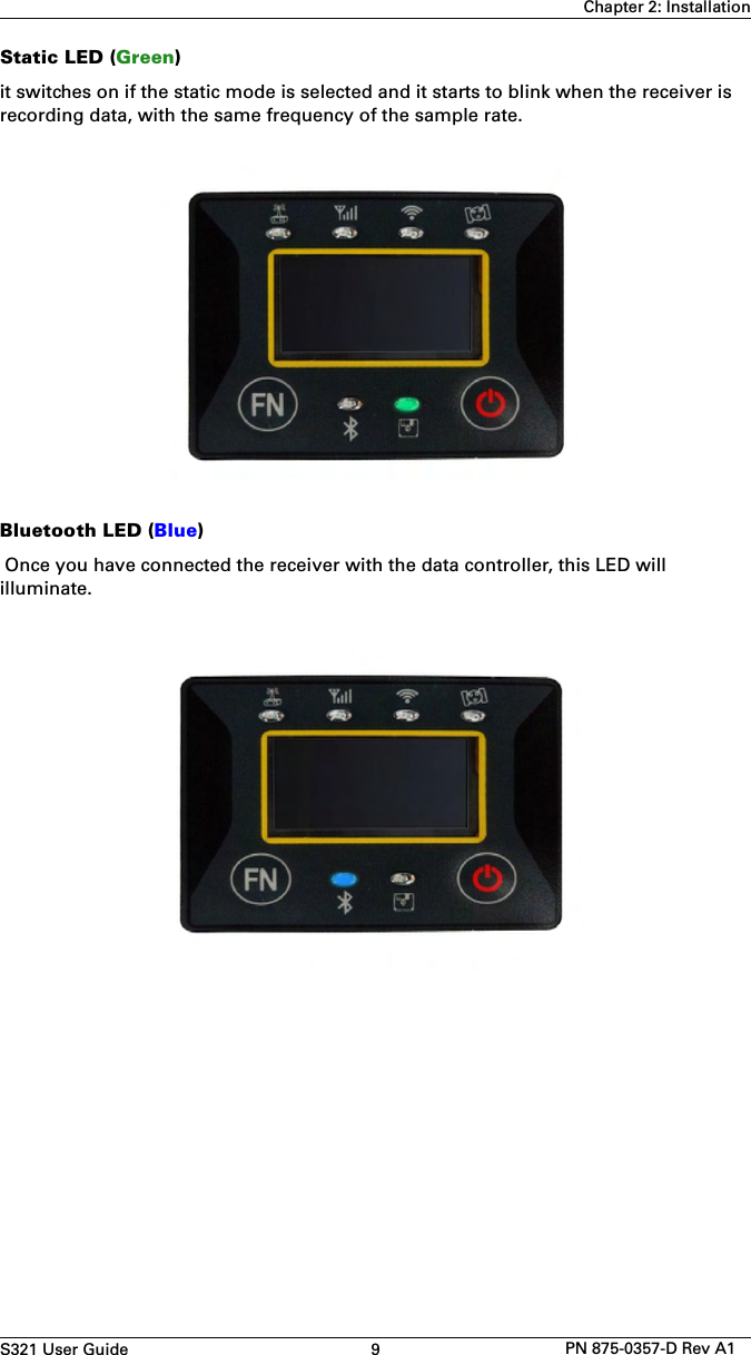

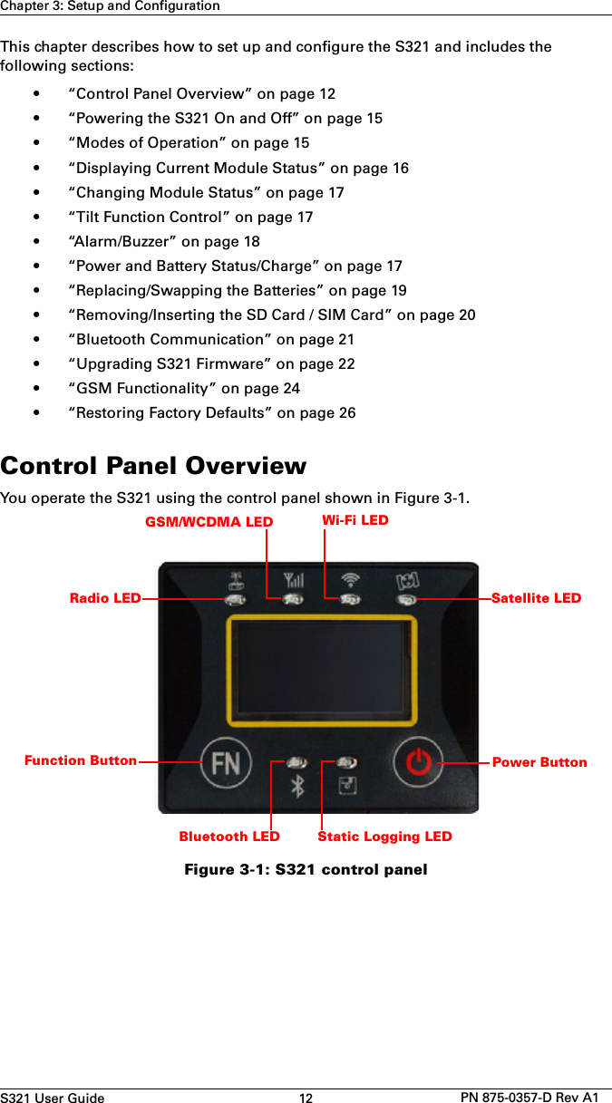
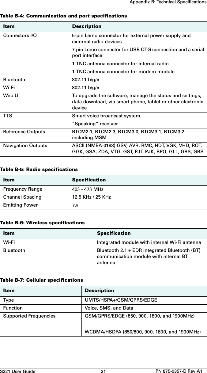
![S321 User Guide 24 PN 875-0357-D Rev A1Chapter 3: Setup and ConfigurationGSM FunctionalityThis section provides advanced GSM information that requires connection to a PC running either Hemisphere GNSS’ PocketMax utility or a terminal program such as HyperTerminal.This section covers the following topics:• GSM overview• GSM modes• Configuring GSM for NTRIP• SMS messagingGSM OverviewGlobal System for Mobile Communications (GSM) is a network technology for mobile phone communications. The GSM modem in the S321 is what allows you to connect to a GSM carrier.The Access Point Name (APN) is a protocol that allows the S321 to access the internet using the mobile phone network. It is a configurable network identifier used when connecting to a GSM carrier. The default APNCFG value is "internet.com". The specific APN required by the S321 depends on your mobile carrier. Check with your mobile provider for details. GSM ModesThe GSM module operates in four modes:• IDLE - Default mode for the module. In this state, the GSM module onlyattempts to register on the network.• DIRECT IP - For users who have direct access to a server providingdifferential corrections.• LINK - For users to establish a link between two S321 modules directly,where the BASE has a dynamic IP address. You should only use this modeon the rover in a base station / rover setup (use IDLE mode for the basestation).• NTRIP - Used to provide differential correction information to the GPSreceiver.Configuring GSM for NTRIPNTRIP (Networked Transport of RTCM via Internet Protocol) is the protocol for transmitting GNSS data over the internet.Note: To configure NTRIP you must connect the S321 to a PC running either Hemisphere GNSS’ PocketMax utility or a terminal program such as HyperTerminal.To configure NTRIP send the following command:$GSMCFG,NTRIP,[remote host name or IP address],[port number],[mount point name],[[username],[password]]where,](https://usermanual.wiki/Hemisphere-GNSS/S321UHF/User-Guide-2926030-Page-37.png)
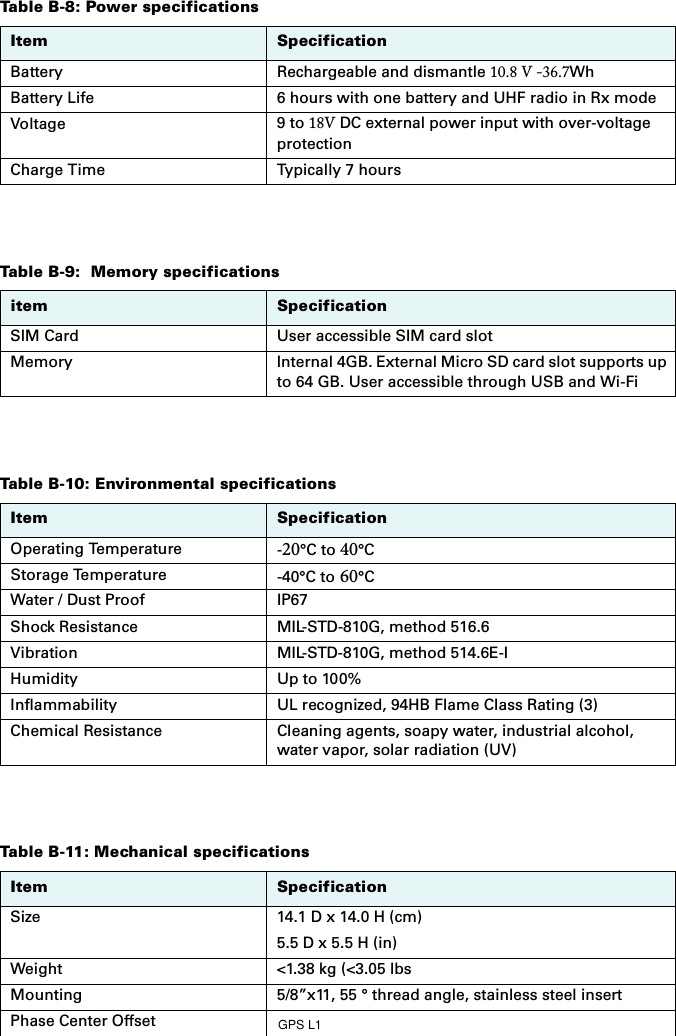
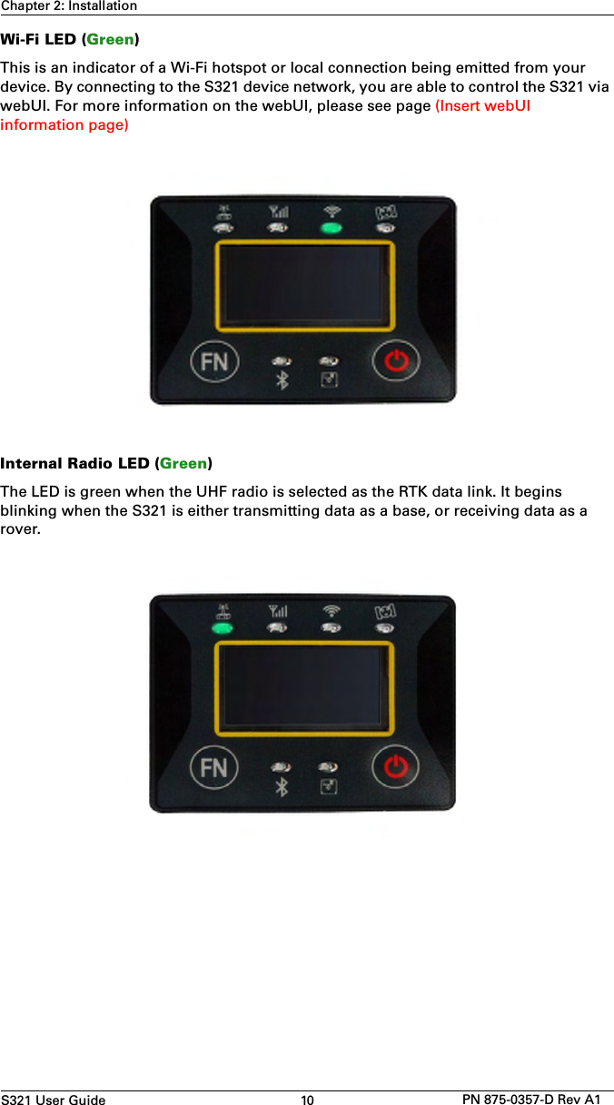
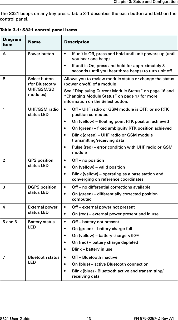
![S321 User Guide 25 PN 875-0357-D Rev A1Chapter 3: Setup and Configuration•Remote host name - server name (such as www.igs-ip.net) or an IP address• Mount point name - caster stream name from NTRIP Caster Source Table(you can download a sample source table from http://www.igs-ip.net:2101/).If you leave this field blank, the S321 will fetch the caster source table andselect the mount point closest to its current position.• User name and password - authentication with a user name and password isrequired for most NTRIP casters. You can leave both blank to specify that noauthentication is required. The user name and password are case sensitive.For example, to connect to the CALG0 stream on igs-ip.net send the following command:$GSMCFG,NRTIP,www.igs-ip.net,2101,CALG0,Usrnam,passwdConfiguring SMS MessagingThe S321 supports Short Message Service (SMS) configuration and event updates for both base and rover operations.When using SMS messaging keep the following in mind:• The GSM module must be powered on for SMS commands to workcorrectly.• You can send SMS messages to the S321 from up to three numbers andthese numbers must be added to the S321 approved numbers list.• By default the approved numbers list is comprised of the first three entries inthe SIM card address book. However, for a typical data-only SIM card, theaddress book of the SIM card will be empty.• Use the appropriate country code (the following procedures use the “+1”country code for USA/Canada).Adding or Overwriting a Number on the Approved Numbers ListYou can add a number to an empty slot or overwrite an existing number using the following command:$JSMS,CONFIG,[slot number 1/2/3],[number],[name],[status messages ON | OFF]For example, to add “Service” (USA phone number 999-555-1212) to slot 1 with status messages OFF (or to replace the current number in slot 1) send the following command:$JSMS,CONFIG,1,+19995551212,Service,OFFThe status message state (ON or OFF) allows the S321 to send an SMS message back to the number to report information and events on the operation of the unit. Displaying the Current List of Approved NumbersTo display the current list of approved numbers send the following command:$JSMS,CONFIGThe reply below contains all the information on the configured numbers and may include SIM card address book defaults that you can overwrite with your own information.$>JSMS,CONFIG,1,1,+19995551212,Service,OFF](https://usermanual.wiki/Hemisphere-GNSS/S321UHF/User-Guide-2926030-Page-38.png)
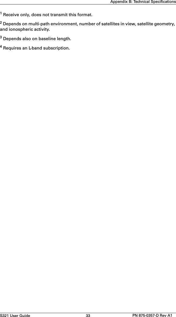
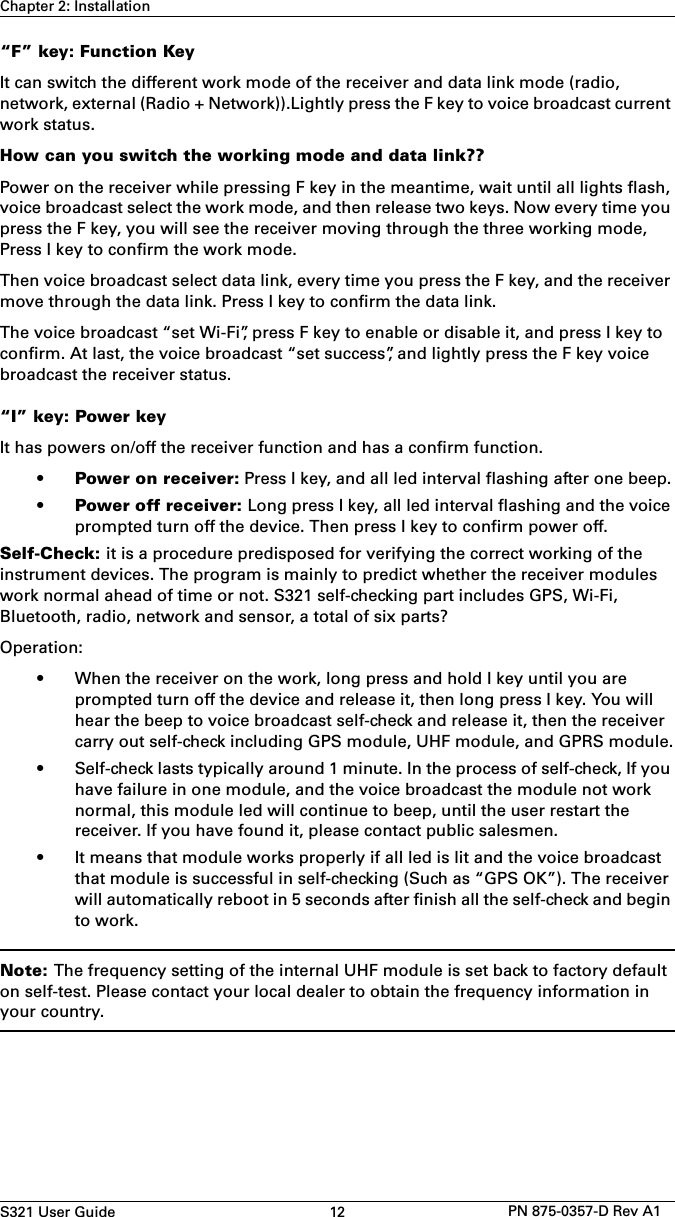
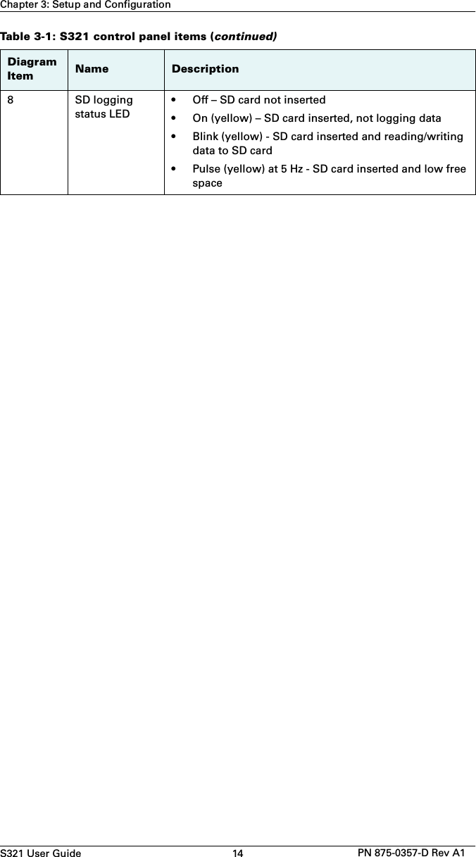
![S321 User Guide 26 PN 875-0357-D Rev A1Chapter 3: Setup and ConfigurationThe format of the reply is:$>JSMS,CONFIG,[number of approved numbers],[slot number 1/2/3],[number],[name],[status messages ON | OFF]Note: The reply contains one line for each number. For example, if there are two approved numbers then the reply will contain a “$>JSMS,CONFIG” line for each number.Deleting a Number from the Approved Numbers ListTo delete a number from the approved numbers list, send the following command:$JSMS,CONFIG,[1/2/3 or keyword ALL],DELETEFor example, to delete the number in slot 2 send the following command:$JSMS,CONFIG,2,DELETEAnd to delete all numbers from the list, send the following command:$JSMS,CONFIG,ALL,DELETESending an SMS Message to an Approved NumberTo send an SMS message to an approved number, send the following command:$JSMS,SEND,[name or phone number or slot number],[message]For example, to send a “This is a test” message to Customer Support (USA phone number 480-348-9919, slot number 2) you can send any of the following commands:$JSMS,SEND,SERVICE,This is a test$JSMS,SEND,+14803489919,This is a test$JSMS,SEND,2,This is a testRestoring Factory DefaultsIf you need to restore your factory defaults for any reason you can do this via the Control panel.To restore factory defaults:• Press and hold the Power button for 10 to 20 seconds and release it whilethe GPS status and DGPS status LEDs are blinking.](https://usermanual.wiki/Hemisphere-GNSS/S321UHF/User-Guide-2926030-Page-39.png)