Herutu Electronics TWF600R Pokayoke Receiver User Manual
Herutu Electronics Corporation Pokayoke Receiver
User Manual
V20060621
POKAYOKE Receiver
[ TWF-600R ]
Operation Manual
V 1.03
HERUTU ELECTRONIC CO., LTD.
62-1 Toyooka, Hamamatsu, Shizuoka, 433-8103 Japan
TEL. 81-53- 438-3555
FAX. 81-53- 438-3411
ⅰ
Safety concerns (Be sure to read)
To prevent human injury of user or damage in property from occurring, be sure to observe the
precautions shown below.
■ The degree in safety hazard and damage generated by the wrong usage while ignoring the
descriptions is classified by the following displays.
Using in an improper way while ignoring this pictorial symbol might cause a
death or serious human injury.
Using in an improper way while ignoring this pictorial symbol might cause a
human injury or property damage.
■The type of descriptions you should observe is classified by the following pictorial symbols.
This pictorial symbol indicates a “Reminder” to attract an attention.
This pictorial symbol indicates a “Prohibition” to prohibit a certain action.
■ For the usage to be commonly applied in all the models:
●Avoid using in a place with a plenty of humidity or dust. Otherwise, absorbing a
dust or water contents may cause machine trouble, fire or electrical shock.
■For handling this machine:
●This is the electronic devise or wireless radios composed of the precision parts.
Do not overhaul/remodel. It may cause accident or machine trouble.
■ For handling this machine:
●Do not use this product for the application needing the high reliability related to
human lives.
●Do not use this product in a place where it is uncertain about whether or not radio
waves reach.
! Warnin
g
!
Caution
!
!
Caution
!
Warning
ⅱ
■For handling the power source:
Be sure to observe the following precautions to prevent the AC adapter and Power cord from being
heated, damaged, or ignited.
●Do not approximate the AC adapter and Power cord to a fire, or do not put them
into a fire. The AC adapter and Power cord can be broken or ignited, resulting in
an accident.
●You can use the AC adapter and main body only with the specified power voltage
to protect them from the damage and fire accident.
●Do not use the AC adapter and main body in a wettable atmosphere. It may cause
accidents or troubles such as heating, igniting or electrical shock.
●Do not touch the AC adapter, main body, Power cord and Plug outlet with wet
hands. It may cause an accident such as electrical shock, etc.
●Do not damage the Power cord. A short-circuit or heating may cause a fire or
electrical shock.
●Do not use the Power plug with dust being adhered.
A short-circuit or heating may cause a fire or electrical shock.
●Do not give a strong impact onto the AC adapter. It may cause an accident or
machine failure.
●If you find out deformed AC adapter, do not use it.
It may cause an accident or machine failure.
●Do not charge this equipment in a place where flammable gas can be generated.
It may cause a fire accident.
●Never overhaul the AC adapter.
It may cause an accident or machine failure.
■When trouble happens during use:
Since it may cause a fire or electrical shock, disconnect a power plug, and immediately ask
outlet store or our company to repair.
●When smoke or abnormal odors are generated, stop using, immediately
disconnect a power plug, and ask outlet store or our company to repair.
●Once the Power cord is damaged, do not use it.
Using it as is may cause a fire or electrical shock.
!
Warning
!

ⅲ
CAUTION
CHANGE OR MODIFICATIONS NOT EXPRESSLY APPROVED BY THE MANUFACTURE FOR
COMPLIANCE COULD VOID THE USER’S AUTHORITY TOOPERATE THE EQUIPMENT
TO REDUCE THE ELECTRIC SHOCK, DO NOT REMOVE SCREWS.
NO USER-SERVICEABLE PARTS INSIDE.
REFER SERVICING TO QUALIFIED SERVICE PERSONNEL.
THE FOLLOWNG APPLIES ONLY IN THE U.S.A
This device complies with Part 15 of the FCC Rules. Operation is subject to the following
two conditions: (1)This device may not cause harmful interface, and (2) This device must
accept any interface received, including interface that may cause undesired operation:
NOTE: This equipment has been tested and found to comply with the
limits for a Class B digital device, pursuant to Part 15 of the FCC Rules.
These limits are designed to provide reasonable protection against harmful
interference in a residential installation. This equipment generates use
and can radiate radio frequency energy and, if not installed and used in
accordance with instructions, may cause harmful interference to radio
communications. However, there is no guarantee that interference will not
occur in a particular installation. If this equipment does cause harmful
interference to radio or television reception, which can be determined by
turning the equipment off and on, the user is encouraged to correct the
interference by one or more of the following measures:
- Reorient or relocate the receiving antenna.
- Increase the separation between the equipment and receiver.
- Connect the equipment into an outlet on a circuit different from that to
which the receiver is connected.
- Consult the dealer or an experienced radio/TV technician for help.
Contents
1.Outline....................................................................................................................................1
2.Specification..........................................................................................................................2
3.Each part name......................................................................................................................4
4.Outline of operation ..............................................................................................................5
4−1.Normal operation........................................................................................................5
4−2.ID login ........................................................................................................................5
4−3.Setting the contact output time.................................................................................6
5.Installation method................................................................................................................7
6.Dimensional drawing ............................................................................................................8
7.Guarantee...............................................................................................................................9

1
1.Outline
This machine receives the frame data transmitted from Transmitter provided with software
which can communicate, and actuates the corresponding output during the preset time.
The frame data transmitted from Transmitter contains ID codes equivalent to 16bit. From
among 65536 type’s codes, two codes, which were previously logged in this machine, can be
received.
(In addition to 65536 types, the type of ID code can be further increased by adding the
exclusive code.)
The codes within the received frame data are compared with the code that was previously
logged in this machine, and only when they are consistent each other, the output (MOS-FET
relay) goes into effect.
(Due to the preset chattering prevention time, it takes 300ms to reach receivable condition
again after MOS-FET relay output.)
You can select the desired MOS-FET Relay output time from among four types of 200ms,
400ms, 600ms and 800ms.
Outline

2
2.Specification
General specification
Items Specification
Model TWF-600R
Appropriate
standard/Regulation
FCC Part15B
IC RSS-210
RoHS
Destination US/Canada
Operating power
voltage DC12V (Operative voltage zone: DC10 to 16V)
Operating power
source
DC Jack
Appropriate plug: Internal diameterφ2.1mm
External diameterφ5.5mm Center-minus
Current consumption 150mA at max when DC12V is input
Working
temperature/humidity
range
Temperature: 0 to + 50°C
Humidity: 85%RH or less (No freezing and condensation)
Electrostatic
withstand pressure 10kV
Noise permissible
zone DCin 250V
Machine dimension 120W x 168H x 38D mm(Raised portion excluded)
Steel case material Steel plate (SECC t=1.0) Painted and printed
Interface
MOS-FET Relay x 4-point (each point independently insulated)
Rated load voltage AC/DC30V per point
Rated load current 0.5A per point
Connection method Screw terminal(M3.5) 8-piece
Power
switch Locker type(Alternate 2-position) 1-piece
Switch ID LOGIN
SWITCH Push-type(Momentary/Illuminated-type) 2-piece
Power
lamp Red LED 1-piece(Light emitting sectionφ5)
Display Receiving
lamp Green LED 2-piece(Light emitting section□9 Also can be used as ID
LOGIN SWITCH)
Accessory Antenna (BNC Connector connected)
Option AC Adapter
Input: AC100V to 240V 50/60Hz
Output: DC12V/1A
Specification

3
Specification
Specification of radio section
Communication
system Unidirectional communication system
Electric wave
type F1D
Modulation
method Binary FSK
Modulation rate 1000bps
Receiver
frequency 426.1 MHz
Receiving circuit
system Double super heterodyne system
Receiving
sensitivity 0dBμVemf or less
Antenna
terminal BNC-J Connector Nominal impedance 50Ω
4
Each part name
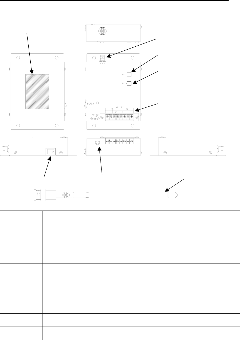
3.Each part name
Items Contents
①Receiving
lamp 1 Receiving lamp corresponding to ID1 (Green LED)
Also can be used as ID1Login switch.
②Receiving
lamp 2 Receiving lamp corresponding to ID2 (Green LED)
Also can be used as ID2 Login switch.
③Output
terminal block Relay output with a total of 4-point where 2-point is for ID1 and 2-point is for ID2
(Screw terminal M3.5)
④BNC
Connector for
Antenna BNC-J Connector. The attached antenna is connected by this part.
⑤Nameplate
label affix point The Model, Serial No, FCC ID, IC CODE and Precautions in usage and etc are
described.
⑥DC Jack for
feeding operating
power
DC Jack for feeding the operating power 12V
Appropriate plug: internal diameter φ2.1mm External diameter φ5.5mm
Center-minus
⑦Power switch BNC-J Connector Nominal impedance 50Ω
⑧Antenna Antenna connected by BNC Connector (Accessory)
⑤Nameplate label affix
point
①Receiving lamp 1
(ID LOGIN SWITCH 1)
②Receiving lamp 2
(ID LOGIN SWITCH 2)
③Output terminal block
⑦Power switch
④BNC Connector
for Antenna
⑥DC Jack DC12V for feeding
operating power ⑧Antenna

5
Outline of operation
4.Outline of operation
4−1.Normal operation
Once this machine receives two kinds of codes, namely, ID1 and ID2, which were previously
logged in, the contact output of either output 1 or output 2 runs during the preset time just as
Receiving lamp 1 or Receiving lamp 2 lights on depending on the received code.
When the code transmitted from Transmitter deployed can only correspond to the output 1, the
output 2 becomes unused (when the input point number of Transmitter is 1-point).
You can select the desired contact output time from among four types of 200ms, 400ms,
600ms and 800ms.
Setting is already established for this machine to prevent double counting in such a way that
next signal cannot be received for 300ms after the last signal is received(unacceptable to
change).
4−2.ID login
Before using this machine, login the ID to decide the ID you need to receive.
You can login two types of ID1 and ID2. Operation can run while only ID1 is logged in with ID2
not being logged in. Besides, the same ID code for between ID1 and ID2 can be set, however,
only the output for ID1 can run in this case.
Also possible to clear the already logged in ID.
Log in and clear the ID according to the following ways:
To login the ID
① Turn on the Power switch while pushing the Receiving lamp corresponding to the ID you
need to log in.
ID1→ID LOGIN SWITCH1 ID2→ID LOGIN SWITCH2
(Receiving lamp can also be used as ID LOGIN SWITCH)
② Verify that the ID LOGIN SWITCH corresponding to ID you need to login is blinking (at
interval of 0.5sec). If it does not blink, try again.
③ Within 30-second put the Transmitter of the ID you need to login into transmitting
condition once.
④ Within 5-second without a break put it into transmitting condition again.
⑤ Once ID is logged in, blinking of ID LOGIN SWITCH turns into lighting.
⑥ After login is finished, turn off the power once and then turn on the power again before
use.
Precautions during operation
*Do not operate another Transmitter in the vicinity of Receiver during login operation.
It may cause an incorrect login.
*Unless login operation is completed within the given time, the ID LOGIN SWITCH will light
off. In such case, try again from the beginning.

6
Outline of operation
To clear the ID
① Turn on the Power switch while pushing the ID LOGIN SWITCH corresponding o the ID you
need to login.
ID1→Receiving lamp1 ID2→Receiving lamp2
(Receiving lamp can also be used as the ID LOGIN SWITCH)
② Verify that the ID LOGIN SWITCH corresponding to the ID you need to login is blinking (at
interval of 0.5sec).
③ Keep pressing the ID LOGIN SWITCH, which is blinking, for 5second.
④ If blinking speed becomes faster when you release ID LOGIN SWITCH, it means that
clearing is completed. To use the machine without a break, turn off the power once and
then turn on the power again.
4−3.Setting the contact output time
You can select the desired contact output time from among four types of 200ms, 400ms,
600ms and 800ms. 200ms is set before shipment.
① Turn on the power while simultaneously pressing two ID LOGIN Switches.
② Once the Power lamp starts blinking, release your hand from ID LOGIN SWITCH.
③ The blinking conditions of Receiving lamp indicate the current output time set values.
ID1 ID2
Contact output
time
lights off lights off 0.2sec
lights on lights off 0.4sec
lights off lights on 0.6sec
lights on lights on 0.8sec
④ To change the setting, manipulate the ID LOGIN SWITCH within 5 seconds.
Once ID LOGIN SWITCH is pressed, the “lights on/lights off” will reverse. Manipulate the
ID LOGIN SWITCH to get the contact output time you need to set.
⑤ Once 5-second passes after stopping ID LOGIN SWITCH manipulation, the set content
can be logged in.
If login is completed, all ID LOGIN Switches lights off and blinking of power lamp turns into
lighting. Then you can operate as-is continuously.
Precautions during operation
*The contact output time is common. It is impossible to set the different output time for each
ID.
*If you do not change the setting, wait for 5-second without manipulating ID LOGIN SWITCH
after the condition of ③ or turn off the power switch.
*If the power switch is turned off during power lamp in blinking, the set content cannot be
logged in.

7
Installation method
5.Installation method
① Install this machine in the place where it can be easily viewed from the Transmitter and
also an electric wave can be stably received.
② Set the antenna so that it is not parallel to the metal plates and keep away it from metal
plates as far as possible.
③ Feed the stable power supply (DC12V) with less variation.
④ Make a wiring for the output terminal block.
Output turns on with relay contact. Once output turns on, short-circuited condition is made
between terminals.
Once the rated contact load is exceeded, inner circuit might be damaged. Use an extreme
care.
Rated load voltage AC/DC30V per point
Rated load current 0.5A per point
Connection method Screw terminal(M3.5) 8-piece
8
Dimensional drawing
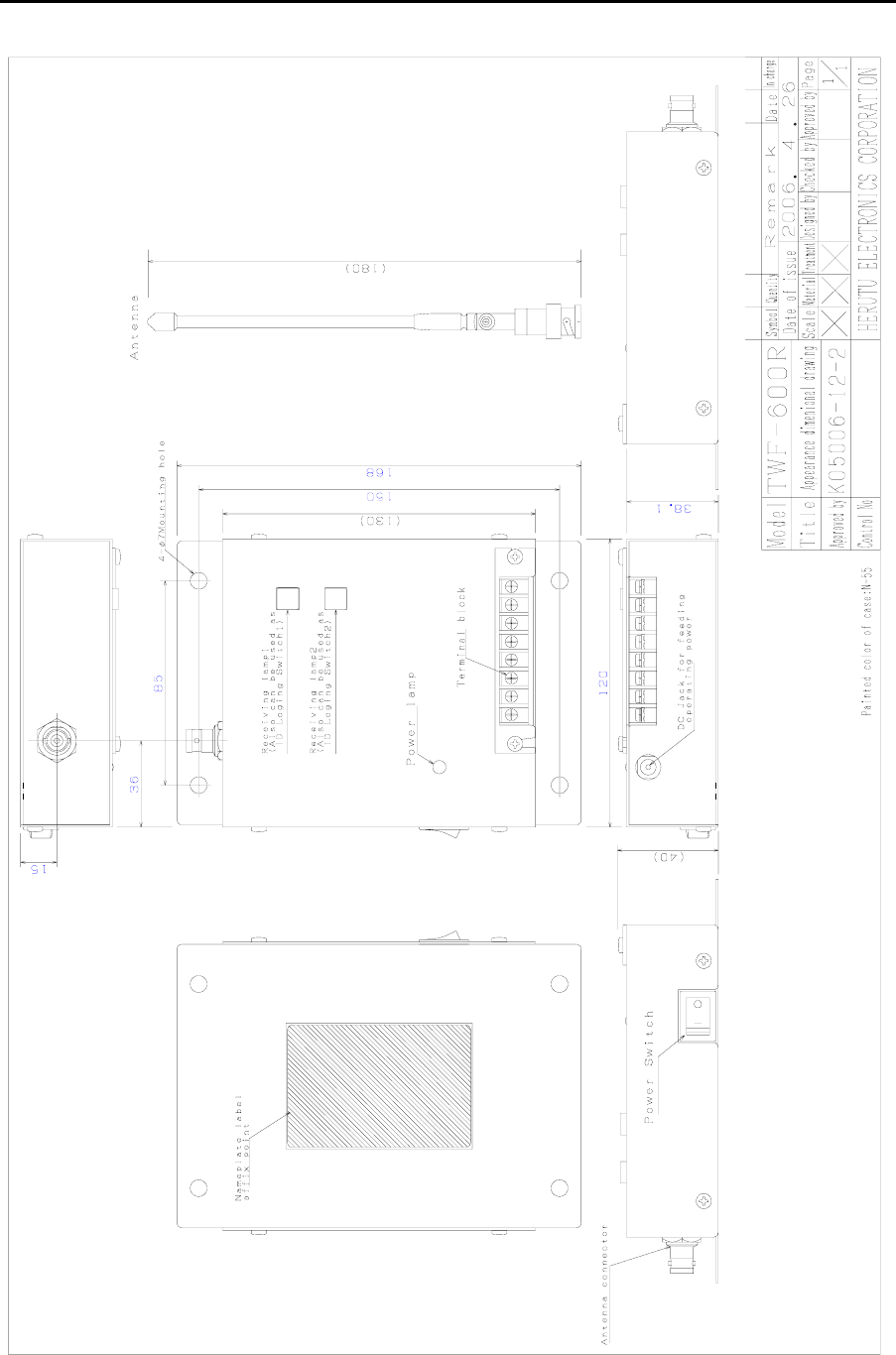
6.Dimensional drawing

9
Guarantee
7.Guarantee
●The guarantee certificate is attached on this product. Confirm the prescribed contents, and
carefully keep it.
●The guarantee period is stated in the guarantee certificate.
We will repair during the guarantee period according to the guarantee provisions without
charge. For other details, see the guarantee certificate.
●For the repair after guarantee period, consult the outlet store through which you purchased or
our sales office.
If the function can be preserved by the repair, we will repair it at some costs on the customer
request.
●As a principle, regardless of the guarantee period, the defect product should be brought into
our company because the measuring instrument is required for adjustment during repair.
Besides, the customer shall bear the transportation cost incurred during transferring to our
company.
If you need official trip repair or replacement machine during guarantee period, consult the
outlet store through which you purchased or our sales office.
●If you have unclear points for the repair or after service during the guarantee period, consult the
outlet store through which you purchased or our sales office.
● The contents in this manual are subject to change without prior notice.
● We take all possible measures for the contents stated in this manual, however,
if it contains doubtful points, contact our sales office.
● We shall not be responsible for any influences resulting from use of this
machine regardless of aforementioned provisions.
● The product specification and appearance are subject to change for further
improvement without prior notice.