Hetronic ERGOF-2G4 Ergo Transmitter User Manual ERGOF 2G4 User s Manual
Hetronic International Inc Ergo Transmitter ERGOF 2G4 User s Manual
UserManual.wiki
>
Hetronic
>
ERGOF 2G4 User Manual
User Manual
Navigation menu
Upload a User Manual
Namespaces
Wiki Guide
HTML
PDF
Info
Views
User Manual
Discussion / Help
Navigation
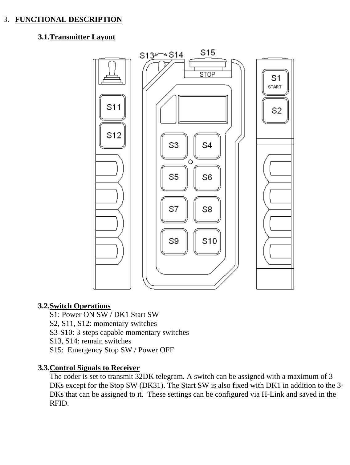
![3.4.Power Supply Functions • Without the Stop key, it is not possible to switch ON the transmitter. • Upon pressing the Start switch, the transmitter will check for a valid RFID in the Stop key. After a valid RFID has been verified, the transmitter will continue power ON operation and enter [Transmit] mode to start transmitting non E-Stop telegrams. During this time, all DKs will remain in neutral status except DK1 and DK32 until the start key is released. • If any of the panel switches (S3~S10) is active when the Start key is pressed to turn ON the transmitter, it shall enter [E-Stop] mode to start transmitting E-Stop telegrams. o If all of the panel switches (S3-S10) is released while the Start key is still pressed, the transmitter shall enter [Transmit] mode to start transmitting non E-Stop telegrams. o If the Start key is released while the abnormal switch is still active (S3~S10), the transmitter shall automatically turn OFF 1sec after the Start key is released. • If the Stop key is active when the Start key is pressed to turn ON the transmitter, it shall enter [E-Stop] mode to start transmitting E-Stop telegrams. If the Stop key is released while the Start key is still pressed, the transmitter shall remain in [E-Stop] and shall automatically turn OFF 1sec after the Stop key is released • If Stop key is pressed during [Transmit] mode, the transmitter shall enter [E-Stop] mode to start transmitting E-Stop telegrams to receiver. The transmitter shall remain in [E-Stop] mode for at least 2secs or while the Stop key is still pressed before it automatically turns OFF. 3.5.Panel Switches Interlocking Functions • The 8 panel switches are paired into 4 from top to bottom, S3/S4, S5/S6, S7/S8, S9/S10. Switch pairs can be interlocked with each other depending on the users setting. By default, switch pairs are interlocked. • Interlock function can be configured via H-Link. 3.6.Auto-OFF Function • During [Transmit] mode, if there is no operation and the switch status remained unchanged for a certain period of time, the transmitter will automatically turn OFF provided that the auto-OFF function is enabled. • Auto-OFF wait time is adjustable via H-Link. 3.7.Low Battery Detection • If a low battery level is detected while in [Transmit] mode, the red led will turn ON. • If the battery level has recovered to 3.65V~ after low battery has been detected, the low battery status and warning indication will be cleared. • If the battery level dropped to ~3.1V while in [Transmit] mode, the transmitter will automatically turn OFF. • The low battery detection level can be set to Normal (~3.4V) or advance (~3.5V). 3.8.H-Link Configurations • Address: 000001~999999 • Duty Cycle: 1% ~ 10% (MFS version) • Frequency Channel Selection • Auto-OFF: Disabled, 1 min ~ 1hr • Panel Switch Interlocking • DK assignments](https://usermanual.wiki/Hetronic/ERGOF-2G4/User-Guide-1420197-Page-4.png)