Hetronic ERGOF-2G4 Ergo Transmitter User Manual ERGOF 2G4 User s Manual
Hetronic International Inc Ergo Transmitter ERGOF 2G4 User s Manual
Hetronic >
User Manual

User’s Manual
ERGOF-2G4

1. DESCRIPTION
The ERGOF-2G4 is a 2.4GHz MFS Transmitter that has eight panel switches that can be configured with
1~3 step switches. It has four digital inputs dedicated to the left and right single step side switches, two
digital inputs for toggle switch with 3 states, and one digital input for E-Stop switch. All switches (except E-
Stop) have configurable DK assignments; a maximum of 3 DKs can be assigned for each switch. The Start
SW has a fixed DK1 assignment in addition to the 3 DKs that can be assigned to it. The E-stop switch is
fixed to DK31.
Note: Operation is subject to the following two conditions: (1) this device may not
cause interference, and (2) this device must accept any interference, including
interference that may cause undesired operation of the device.
2. TECHNICAL SPECIFICATIONS
Temperature Range -20o to +70o Celsius
Supply Voltage Range 3.3 to 5.0Vdc
Current Consumption <30mA at 3.6Vdc
Inputs Eight 3-step switches
Four 1-step side-switches
R-O-R Toggle Switch
Stop switch
Output LED Indicators (Red / Green)
RF Telegram
Note: The user is cautioned that changes or modifications not expressly approved by
the party responsible for compliance could void the user’s authority to operate the
equipment.
3. FUNCTIONAL DESCRIPTION
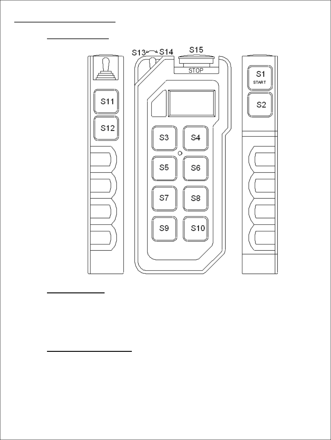
3.1.Transmitter Layout
3.2.Switch Operations
S1: Power ON SW / DK1 Start SW
S2, S11, S12: momentary switches
S3-S10: 3-steps capable momentary switches
S13, S14: remain switches
S15: Emergency Stop SW / Power OFF
3.3.Control Signals to Receiver
The coder is set to transmit 32DK telegram. A switch can be assigned with a maximum of 3-
DKs except for the Stop SW (DK31). The Start SW is also fixed with DK1 in addition to the 3-
DKs that can be assigned to it. These settings can be configured via H-Link and saved in the
RFID.

3.4.Power Supply Functions
• Without the Stop key, it is not possible to switch ON the transmitter.
• Upon pressing the Start switch, the transmitter will check for a valid RFID in the Stop
key. After a valid RFID has been verified, the transmitter will continue power ON
operation and enter [Transmit] mode to start transmitting non E-Stop telegrams. During
this time, all DKs will remain in neutral status except DK1 and DK32 until the start key
is released.
• If any of the panel switches (S3~S10) is active when the Start key is pressed to turn ON
the transmitter, it shall enter [E-Stop] mode to start transmitting E-Stop telegrams.
o If all of the panel switches (S3-S10) is released while the Start key is still
pressed, the transmitter shall enter [Transmit] mode to start transmitting non E-
Stop telegrams.
o If the Start key is released while the abnormal switch is still active (S3~S10), the
transmitter shall automatically turn OFF 1sec after the Start key is released.
• If the Stop key is active when the Start key is pressed to turn ON the transmitter, it shall
enter [E-Stop] mode to start transmitting E-Stop telegrams. If the Stop key is released
while the Start key is still pressed, the transmitter shall remain in [E-Stop] and shall
automatically turn OFF 1sec after the Stop key is released
• If Stop key is pressed during [Transmit] mode, the transmitter shall enter [E-Stop] mode
to start transmitting E-Stop telegrams to receiver. The transmitter shall remain in [E-
Stop] mode for at least 2secs or while the Stop key is still pressed before it automatically
turns OFF.
3.5.Panel Switches Interlocking Functions
• The 8 panel switches are paired into 4 from top to bottom, S3/S4, S5/S6, S7/S8, S9/S10.
Switch pairs can be interlocked with each other depending on the users setting. By
default, switch pairs are interlocked.
• Interlock function can be configured via H-Link.
3.6.Auto-OFF Function
• During [Transmit] mode, if there is no operation and the switch status remained
unchanged for a certain period of time, the transmitter will automatically turn OFF
provided that the auto-OFF function is enabled.
• Auto-OFF wait time is adjustable via H-Link.
3.7.Low Battery Detection
• If a low battery level is detected while in [Transmit] mode, the red led will turn ON.
• If the battery level has recovered to 3.65V~ after low battery has been detected, the low
battery status and warning indication will be cleared.
• If the battery level dropped to ~3.1V while in [Transmit] mode, the transmitter will
automatically turn OFF.
• The low battery detection level can be set to Normal (~3.4V) or advance (~3.5V).
3.8.H-Link Configurations
• Address: 000001~999999
• Duty Cycle: 1% ~ 10% (MFS version)
• Frequency Channel Selection
• Auto-OFF: Disabled, 1 min ~ 1hr
• Panel Switch Interlocking
• DK assignments