User Manual

User’s Manual
MFS USB DONGLE

1. DESCRIPTION
The MFS USB Dongle is a small, USB to RF modem designed to communicate with MFS
systems operating in the 915MHz and 2400MHz frequency bands. The standard firmware load
enables H-Link connectivity with the PC platform, but it is possible that this firmware be changed
for other purposed (Tx / Rx Simulator, etc.).
2. FCC AND IC INFORMATION
FCC ID Number: LW9-MFSUSBMDM
IC ID Number: 2119B-MFSUSBMDM
Note: Operation is subject to the following two conditions: (1) this device may not cause
interference, and (2) this device must accept any interference, including interference
that may cause undesired operation of the device.
Note: The user is cautioned that changes or modifications not expressly approved by the
party responsible for compliance could void the user’s authority to operate the
equipment.
Note: The MFS USB Dongle is shipped with the FCC/IC ID label attached. The
FCC/IC ID label must not be removed.
Remarque : L'opération est soumis à deux conditions suivantes: (1) ce dispositif ne peut
pas causer de brouillage, et (2) ce dispositif doit accepter toute interférence, y compris le
brouillage qui peut causer intempestif de fonctionnement du dispositif.
Remarque : L'utilisateur est averti que les changements ou modifications non
expressément approuvées par la partie responsable de la conformité pouvaient annuler
l'autorisation l'utilisateur à faire fonctionner l'équipement.
Note : Le Dongle USB de MFS est livré avec le label ID FCC/IC attaché. L'étiquette de
la FCC/IC ID ne doit pas être supprimé.
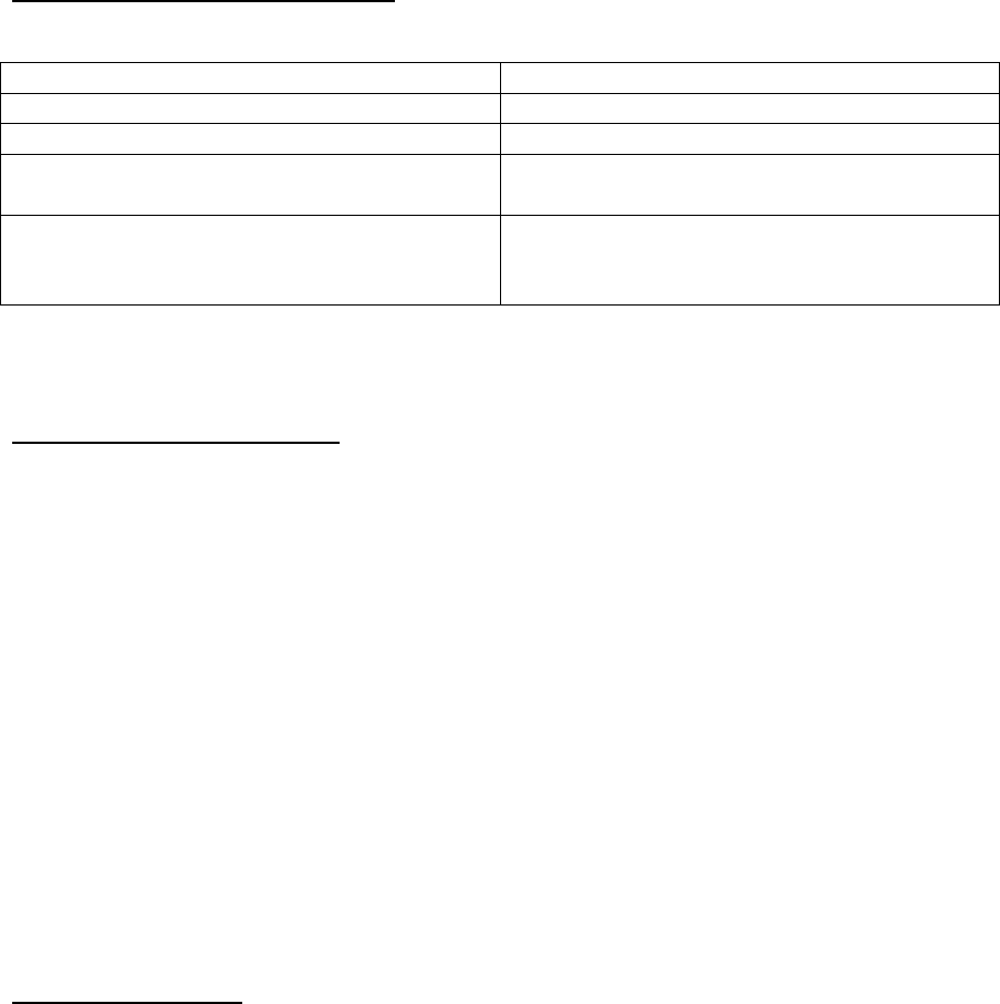
3. TECHNICAL SPECIFICATIONS
Temperature Range -20° to +70° Celsius
Supply Voltage Range 5V USB
Supply Current <30mA
Outputs RF: 915MHz and 2400MHz H-Link Data,
USB PC Interface
Inputs RF: 915MHz and 2400MHz H-Link Data,
Transmitter Control Data,
USB PC Interface
Table 1, Technical Specifications
4. ASSEMBLY DESCRIPTION
4.1. Test / Programming Jumper Configuration
N/A – no firmware/software required for operation.
4.2. Operational Jumper Configuration
N/A – no Jumper configurations required for operation.
4.3. Wiring
N/A – no wiring required for operation.
4.4. Glue and Lacquer Masks
N/A – no Glue or Lacquer masks are required for operation.
5. Connection Diagram
The device connects to a standard PC/Laptop USB port. Currently, only Windows XP and
Windows 7 operating systems are supported.