Hetronic MILLER-FC Foot Pedal Control Transmitter User Manual User s Manual Miller Foot Control
Hetronic International Inc Foot Pedal Control Transmitter User s Manual Miller Foot Control
Hetronic >
manual

User’s Manual
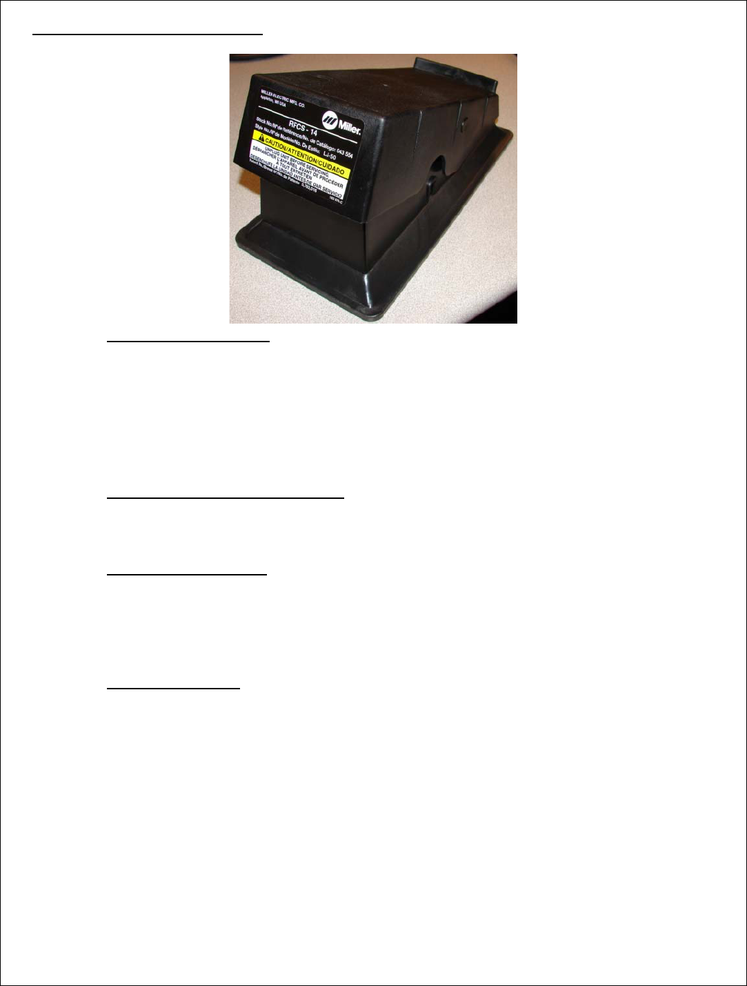
Miller Foot Control

1. DESCRIPTION
The Miller Foot Control (M-TX or Foot Pedal) is a transmitter with one analog channel. The module
is equipped with variable R.F. duty cycle, and variable turn off time (30 seconds for Footpedal). It
operates on 2 selected channels from 16 selectable 2.4GHz frequency channels.
Note: Operation is subject to the following two conditions: (1) this device may not
cause interference, and (2) this device must accept any interference that may cause
undesired operation of the device.
2. TECHNICAL SPECIFICATIONS
Note: The user is cautioned that changes or modifications not expressly approved by
the party responsible for compliance could void the user’s authority to operate the
equipment.
Temperature Range -30o to +70o Celsius
Supply Voltage Range 3-10Vdc
Supply Current 10mA max after 5 seconds settling time
Inputs 1 Power Switch
1 Analog (Potentiometer Input)
Outputs 2.4 GHz 1-10% Duty Cycle
Low voltage detection level 3.4~3.5Vdc (Adjustable to Low/Mid/High)
Shutdown voltage level 2.7Vdc
3. FUNCTIONAL DESCRIPTION
3.1.Transmitter Operation
• This transmitter is designed to be used with RF-transmission duty cycle of 1% to 10%.
• Upon closing the PWR SW, the coder will turn ON and start RF-transmission of non-Stop
telegrams with active DK3, the safety DK for the analog input.
• DK3 is active if there is no potentiometer error and the PWR SW in ON.
• The analog input is converted into 8-bit data (0x00~0xFF) and transmitted as DK17~DK24
with DK17 as LSB.
3.2.Potentiometer Open Error Detect
The unit is equipped with potentiometer error detection. It detects if the potentiometer is
broken (open) or not connected.
3.3.Low Voltage Indicator
The unit has a low battery detection function. The level can be programmed (the actual
voltage is not programmed, just Short, Medium, Long delay before the batteries die). If the
input voltage reaches a critical level (2.7~2.85Vdc) the transmitter will automatically
shutdown.
3.4.Learning Function
The system has a learning function to allow users to pair a decoder to a coder’s channel and
address settings. The procedure to use the learning function is as follows:
3.4.1. Press and hold the learning button on the decoder.
3.4.2. Press pedal to maximum and hold.
3.4.3. The decoder’s green LED will begin blinking rapidly to indicate data is being
received from the coder and that the learning function is complete.
3.4.4. Release the decoder’s learning switch.
NOTE: Learning is only possible during the first 2 seconds that the M-TX is at maximum output.
The Receiver will only learn if the Pedal is close to the Receiver. The address of the RX and
M-TX are combined so only this pair is bound. Receiver Main-Contact will not close until
second activation.