Hetronic PDM Proximity detection module User Manual PDMX
Hetronic International Inc Proximity detection module User Manual PDMX
UserManual.wiki
>
Hetronic
>
PDM User Manual
User Manual
Navigation menu
Upload a User Manual
Namespaces
Wiki Guide
HTML
PDF
Info
Views
User Manual
Discussion / Help
Navigation
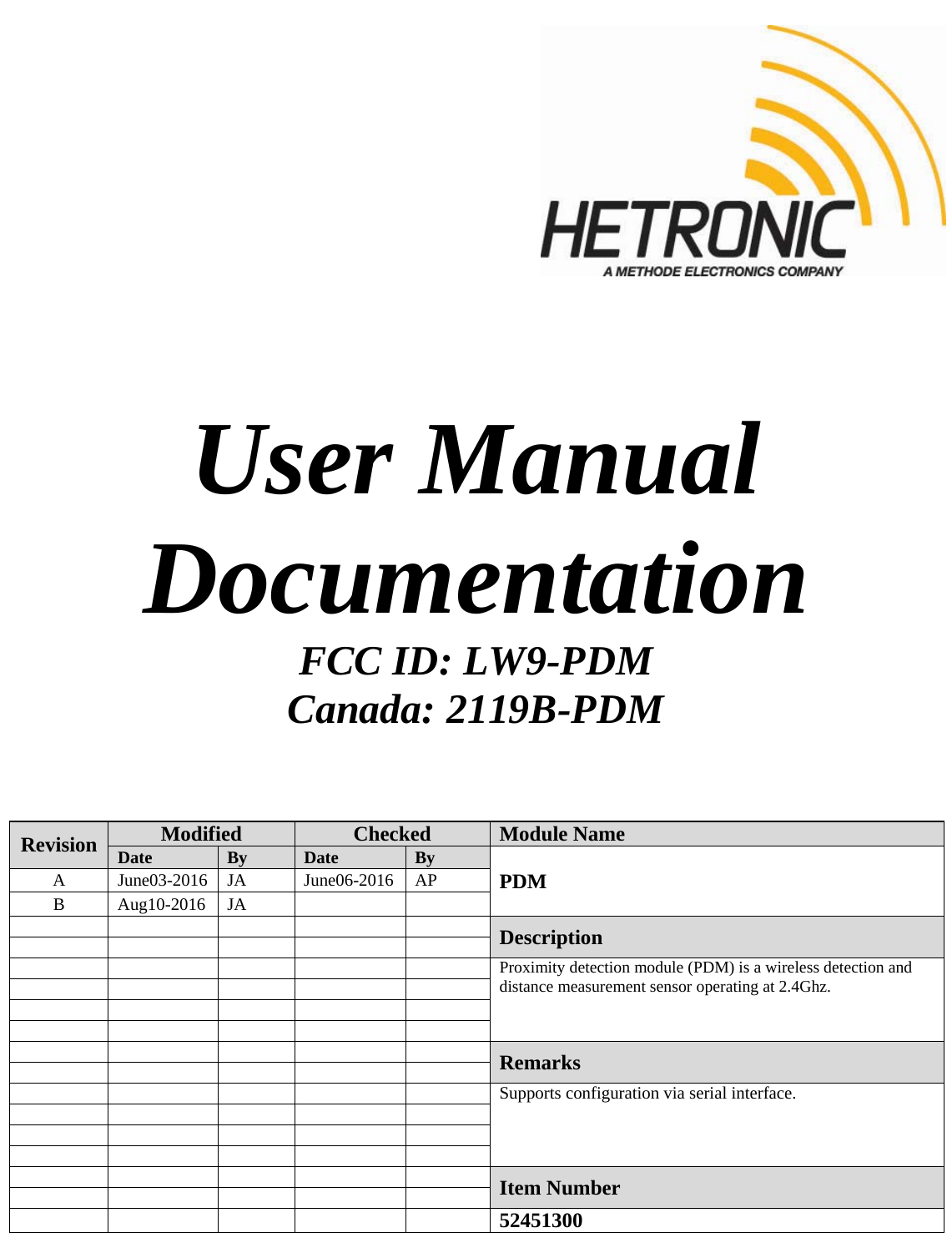
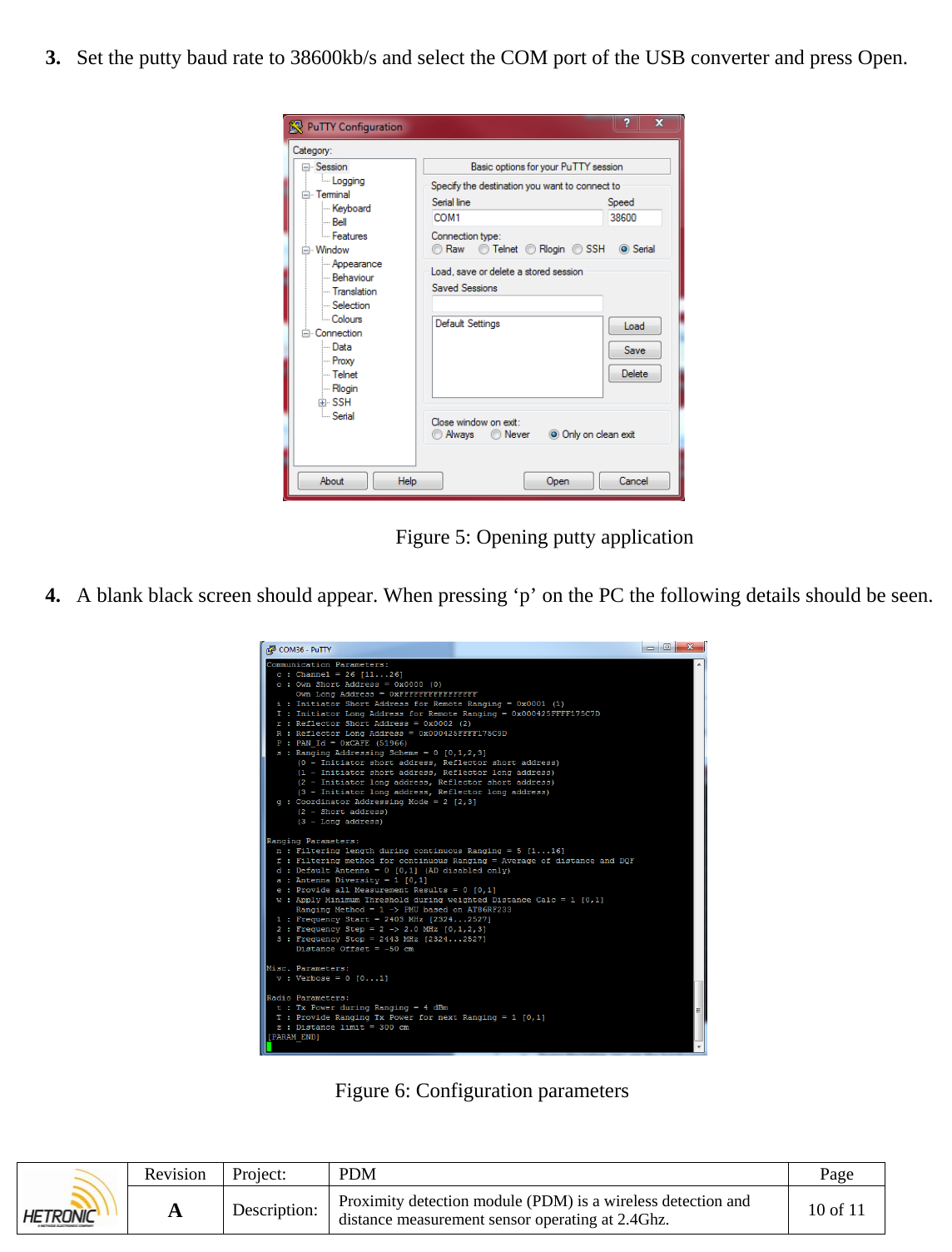
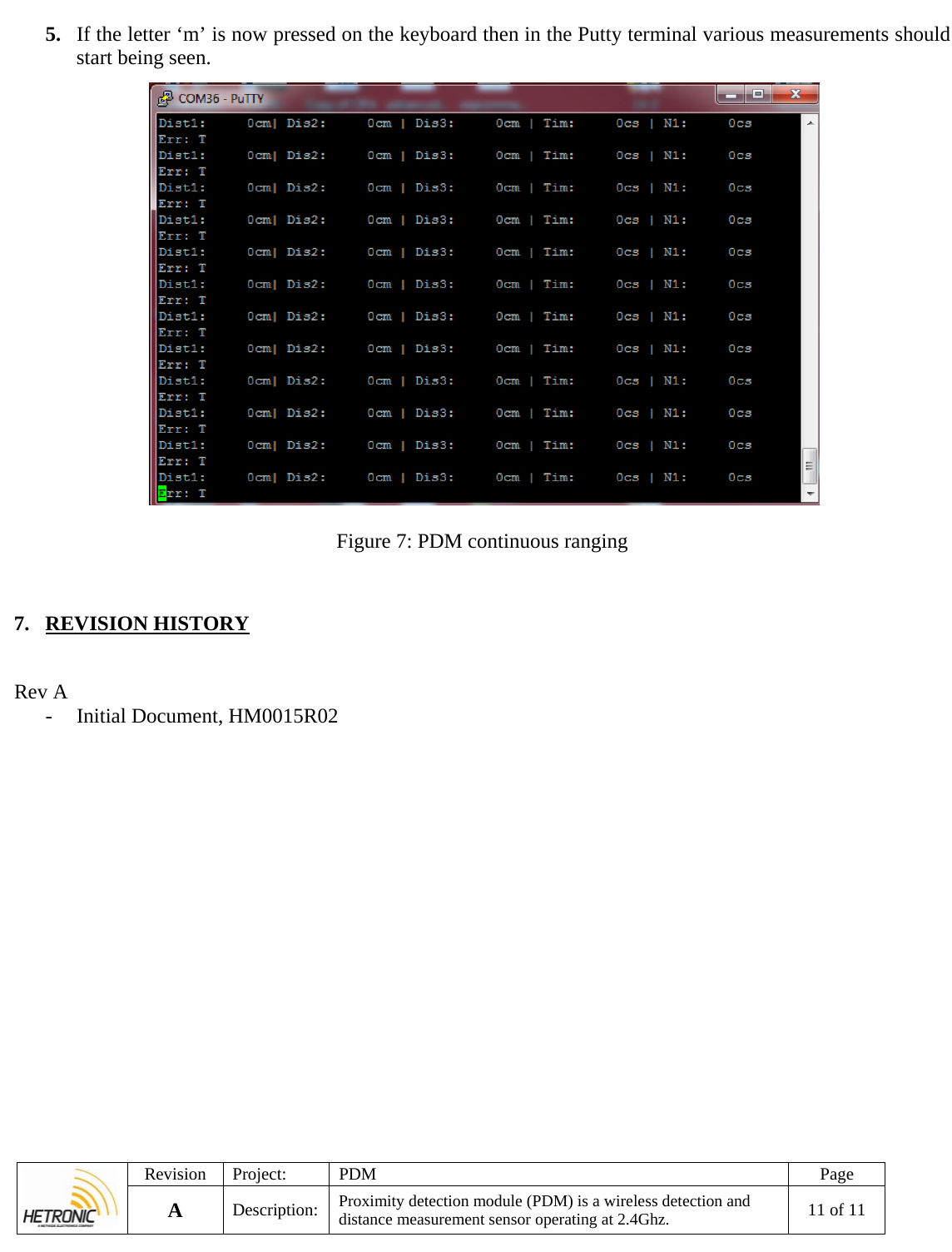
![Revision Project: PDM Page A Description: Proximity detection module (PDM) is a wireless detection and distance measurement sensor operating at 2.4Ghz. 8 of 11 Table 2: PDM configuration parameters Communication parameters Command Description Comment c Channel IEEE802.15.4 channel for basic communication between nodes [11,12,..26] o Own Short Address Node Short address. Used when doing local ranging. i Receiver short address Receiver short address for local ranging. p PAN-ID PAN-ID of ranging network s Ranging Addressing scheme 0 – Transmitter short address, receiver short address g Adressing Mode 2 – Short address Ranging Parameters n Filtering length during continuous ranging Value > 1 starts a continuous ranging with filter depth of n. Stopped by entering ‘m’ or ‘M’ f Filtering method for continuous ranging Filtering methode applied during continuous ranging (n!=1) d Default Antenna Utilized default antenna in case antenna diversity is switched off [0,1] a Antenna diversity Utilization of antenna diversity is supported by the PAL[0,1] 1 Frequency start Ranging measurement start frequency in MHz [2324 – 2527]2 Frequency Step Ranging measurement frequency step mapping [0..3] 3 Frequency stop Ranging measurement stop frequency in MHz [2324 – 2527] Radio Parameters t Tx Power during Ranging TX power in dBm utilized during the actual ranging measurement cycle [-17…4] z Distance limit The distance value that you want to set and monitor. 5.1. LED Description Table 3: PDM LEDs LED Color Description LED1 Red Power supply is on LED2 Yellow Blinking once module starts i](https://usermanual.wiki/Hetronic/PDM/User-Guide-3405217-Page-8.png)
![Revision Project: PDM Page A Description: Proximity detection module (PDM) is a wireless detection and distance measurement sensor operating at 2.4Ghz. 9 of 11 6. PROGRAMMING CONFIGURATION AND TESTING PROCEDURE [Tools Needed / Requirements] Putty software Atmel Flip software USB to Uart converter cable Atmel Studio Atmel ICE with JTAG adaptor Mini USB cable 1. Connect supply to X1 and see that current consumption is between 30-40mA. 2. Open Putty and connect USB to TTL converter cable to connector X2 as shown below. [Test Set-Up] Sample Module Module under test Figure 4: Test setup +5GND+5GND USB to TTL Converter PC](https://usermanual.wiki/Hetronic/PDM/User-Guide-3405217-Page-9.png)