Hetronic PDM Proximity detection module User Manual PDMX
Hetronic International Inc Proximity detection module User Manual PDMX
Hetronic >
User Manual

Revision Modified Checked Module Name
Date By Date By PDM
A June03-2016 JA June06-2016 AP
B Aug10-2016 JA
Description
Proximity detection module (PDM) is a wireless detection and
distance measurement sensor operating at 2.4Ghz.
Remarks
Supports configuration via serial interface.
Item Number
52451300
User Manual
Documentation
FCC ID: LW9-PDM
Canada: 2119B-PDM

Revision Project: PDM Page
A Description: Proximity detection module (PDM) is a wireless detection and
distance measurement sensor operating at 2.4Ghz. 2 of 11
List Of Contains
1.PROJECT DESCRIPTION ............................................................................................................................. 3
2.BLOCK DIAGRAM ....................................................................................................................................... 4
3.TECHNICAL SPECIFICATION .................................................................................................................... 5
4.CONNECTION DIAGRAM ........................................................................................................................... 6
5.CONFIGURATION PARAMETERS ............................................................................................................. 7
6.PROGRAMMING CONFIGURATION AND TESTING PROCEDURE ..................................................... 9
7.REVISION HISTORY .................................................................................................................................. 11
List of Figures
Figure 1: Block Diagram ........................................................................................................................................ 4
Figure 2: Board Connections .................................................................................................................................. 6
Figure 3: PDM configuration parameters ............................................................................................................... 7
Figure 4: Test setup ................................................................................................................................................. 9
Figure 5: Opening putty application ..................................................................................................................... 10
Figure 6: Configuration parameters ...................................................................................................................... 10
Figure 7: PDM continuous ranging....................................................................................................................... 11
List of Tables
Table 1: Technical Specifications Details ............................................................................................................... 5
Table 2: PDM configuration parameters ................................................................................................................. 8
Table 3: PDM LEDs ............................................................................................................................................... 8
Table 4: PCB Specifications Details ...................................................................... Error! Bookmark not defined.

Revision Project: PDM Page
A Description: Proximity detection module (PDM) is a wireless detection and
distance measurement sensor operating at 2.4Ghz. 3 of 11
1. PROJECT DESCRIPTION
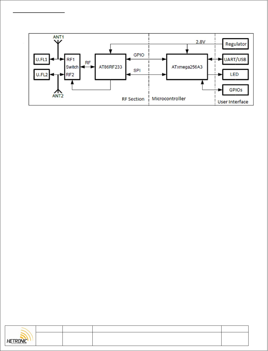
Proximity Detection Module is an RF module designed to measure the distance between two nodes. The
module uses Atmel AT86R233 phase difference measurement function in order to relate change of signal
phase with distance. The module operates in the 2.4 GHz band in order to communicate between two paired
nodes.
The sensor was designed in order to be integrated with Hetronic standard systems. By adding a PDM
module in a transmitter and receiver one can choose the location where the operator has to be in order to
operate the system. The user can choose to either operate the system when he is less than a configurable
distance to the receiving PDM node or else when he is far away by the selected distance.
Revision Project: PDM Page
A
Description:
Proximity detection module (PDM) is a wireless detection and
distance measurement sensor operating at 2.4Ghz.
4 of 11
2. BLOCK DIAGRAM
Figure 1: Block Diagram

Revision Project: PDM Page
A Description: Proximity detection module (PDM) is a wireless detection and
distance measurement sensor operating at 2.4Ghz. 5 of 11
3. TECHNICAL SPECIFICATION
Table 1: Technical Specifications Details
Operating Temperature -20o to +70o Celsius
Storage Temperature -40o to +85o Celsius
Supply Voltage Range 3-12 VDC, 40mA Max
Communication Interface UART, USB
Outputs/Outputs 3 configurable IOs
High current open drain output
Accuracy (line of sight) <5m – 1m accuracy
>5m – 2m and above
Revision Project: PDM Page
A Description: Proximity detection module (PDM) is a wireless detection and
distance measurement sensor operating at 2.4Ghz. 6 of 11
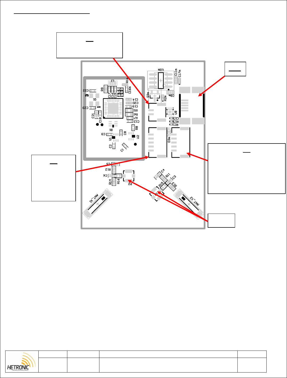
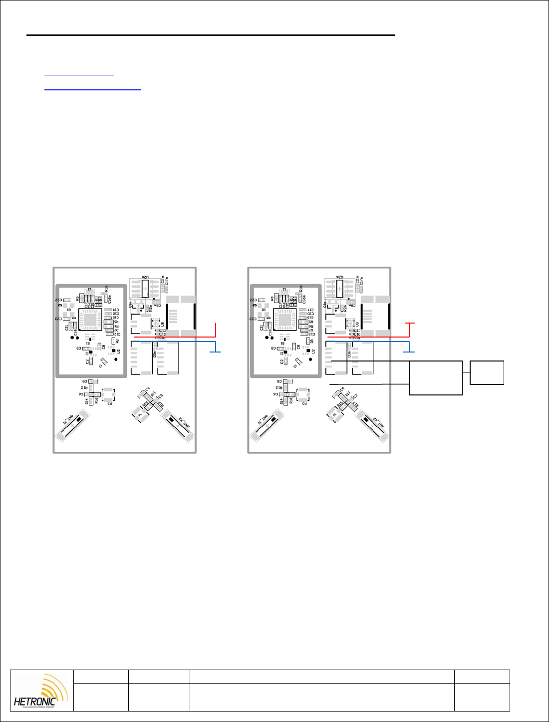
4. CONNECTION DIAGRAM
4.1. Board Connections
Figure 2: Board Connections
X1
1. Vsupply 3-12V
2. GND
X3
1. GND
2. uC_Reset
3. RXD
4. 2.8V
5. TXD
X4
1. GND
2. Open drain output
3. GPIO3
4. Output Low in zone
5. Output High in zone
USB
U.FL
Revision Project: PDM Page
A
Description:
Proximity detection module (PDM) is a wireless detection and
distance measurement sensor operating at 2.4Ghz.
7 of 11
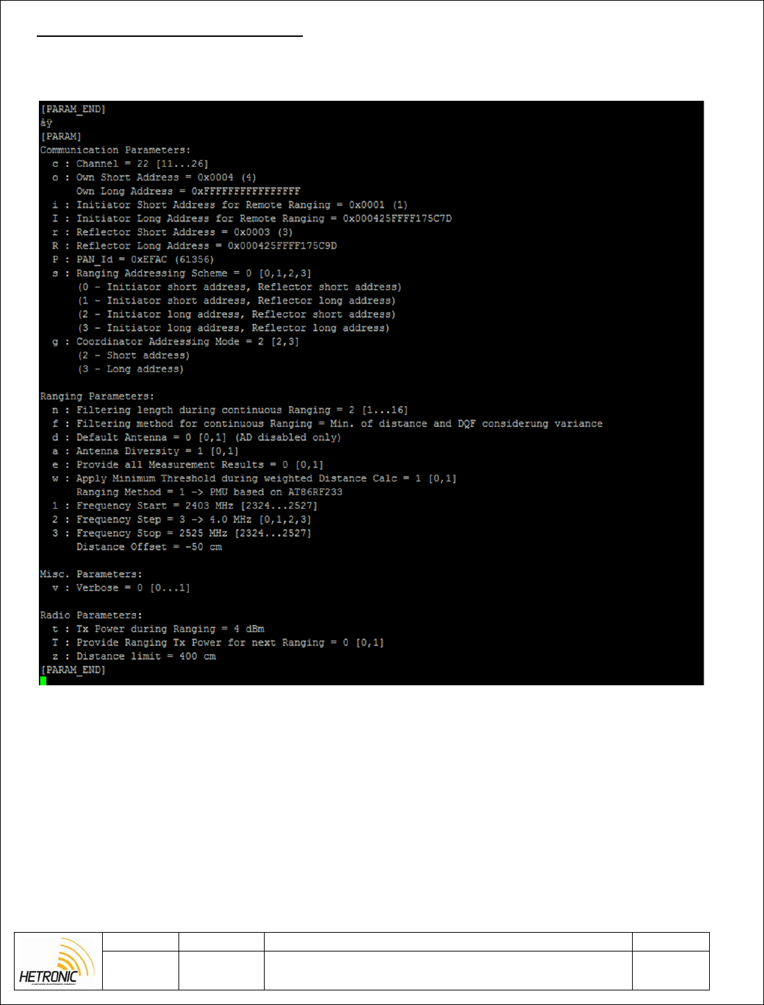
5. CONFIGURATION PARAMETERS
When connecting with a serial interface to the PDM module one can configure the RF parameters and edit
the communications parameters of the sensor. An example of the parameters available is shown below.
Figure 3: PDM configuration parameters
Addresses can be configured via the serial interface and go up to a sixteen bit value. The address for the
receiver has to be the same as the transmitter address plus one. The receiver address has to be updated as the
reflector short address in the transmitter and own short address in the receiver.
Revision Project: PDM Page
A Description: Proximity detection module (PDM) is a wireless detection and
distance measurement sensor operating at 2.4Ghz. 8 of 11
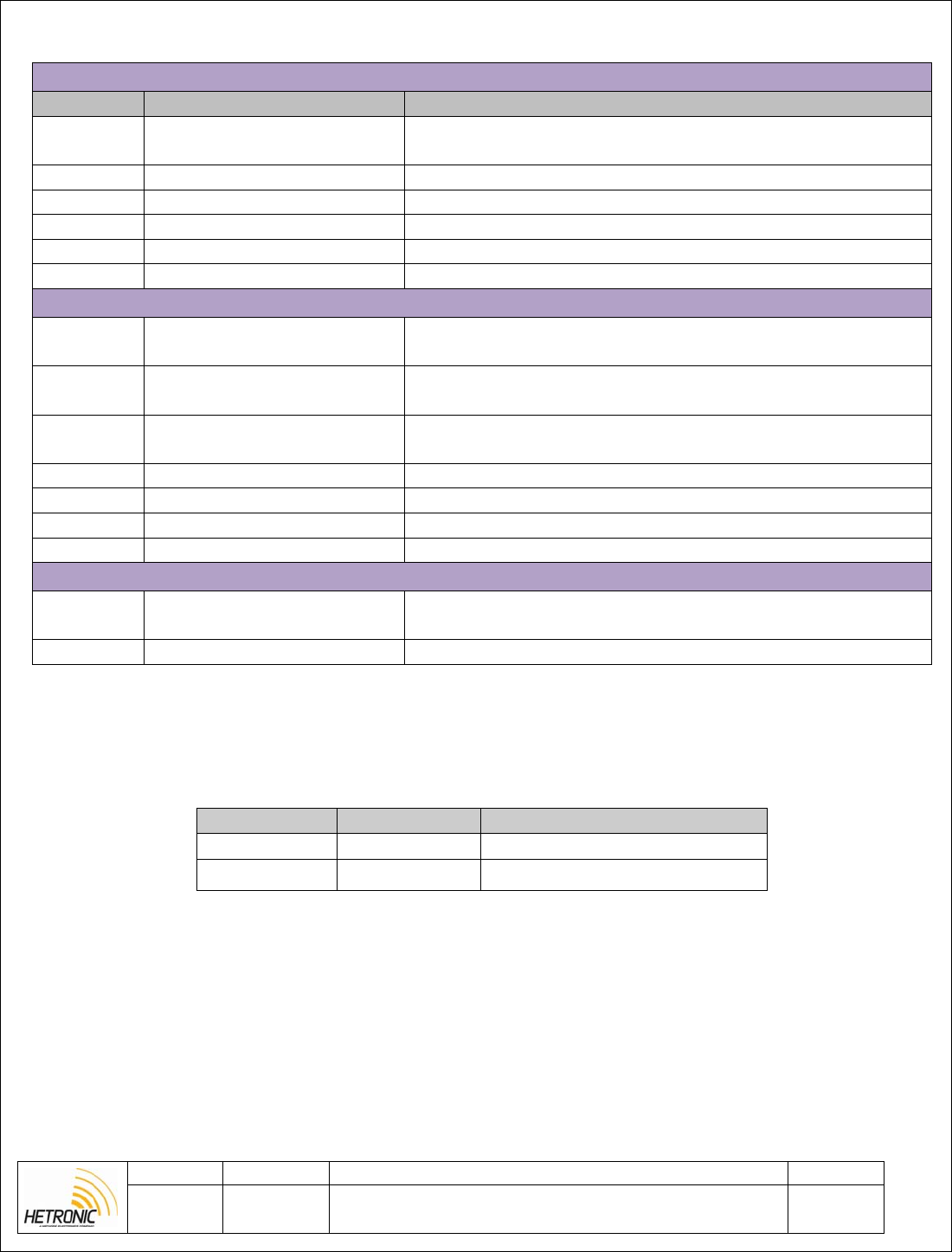
Table 2: PDM configuration parameters
Communication parameters
Command Description Comment
c Channel IEEE802.15.4 channel for basic communication between
nodes [11,12,..26]
o Own Short Address Node Short address. Used when doing local ranging.
i Receiver short address Receiver short address for local ranging.
p PAN-ID PAN-ID of ranging network
s Ranging Addressing scheme 0 – Transmitter short address, receiver short address
g Adressing Mode 2 – Short address
Ranging Parameters
n Filtering length during
continuous ranging Value > 1 starts a continuous ranging with filter depth of n.
Stopped by entering ‘m’ or ‘M’
f Filtering method for
continuous ranging Filtering methode applied during continuous ranging (n!=1)
d Default Antenna Utilized default antenna in case antenna diversity is switched
off [0,1]
a Antenna diversity Utilization of antenna diversity is supported by the PAL[0,1]
1 Frequency start Ranging measurement start frequency in MHz [2324 – 2527]
2 Frequency Step Ranging measurement frequency step mapping [0..3]
3 Frequency stop Ranging measurement stop frequency in MHz [2324 – 2527]
Radio Parameters
t Tx Power during Ranging TX power in dBm utilized during the actual ranging
measurement cycle [-17…4]
z Distance limit The distance value that you want to set and monitor.
5.1. LED Description
Table 3: PDM LEDs
LED Color Description
LED1 Red Power supply is on
LED2 Yellow Blinking once module starts
i
Revision Project: PDM Page
A Description: Proximity detection module (PDM) is a wireless detection and
distance measurement sensor operating at 2.4Ghz. 9 of 11
6. PROGRAMMING CONFIGURATION AND TESTING PROCEDURE
[Tools Needed / Requirements]
Putty software
Atmel Flip software
USB to Uart converter cable
Atmel Studio
Atmel ICE with JTAG adaptor
Mini USB cable
1. Connect supply to X1 and see that current consumption is between 30-40mA.
2. Open Putty and connect USB to TTL converter cable to connector X2 as shown below.
[Test Set-Up]
Sample Module Module under test
Figure 4: Test setup
+5
GND
+5
GND
USB to
TTL
C
onverte
r
PC
Revision Project: PDM Page
A Description: Proximity detection module (PDM) is a wireless detection and
distance measurement sensor operating at 2.4Ghz. 10 of 11
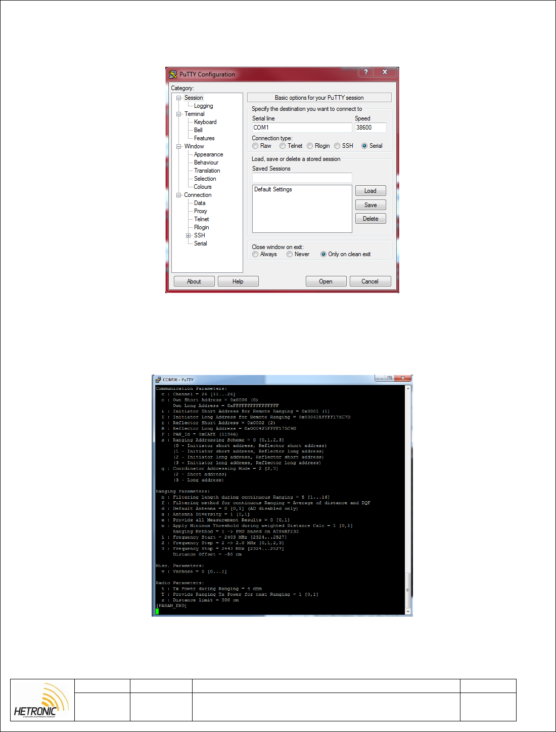
3. Set the putty baud rate to 38600kb/s and select the COM port of the USB converter and press Open.
Figure 5: Opening putty application
4. A blank black screen should appear. When pressing ‘p’ on the PC the following details should be seen.
Figure 6: Configuration parameters
Revision Project: PDM Page
A Description: Proximity detection module (PDM) is a wireless detection and
distance measurement sensor operating at 2.4Ghz. 11 of 11
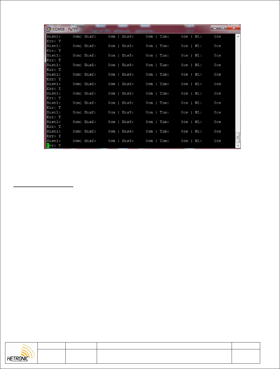
5. If the letter ‘m’ is now pressed on the keyboard then in the Putty terminal various measurements should
start being seen.
Figure 7: PDM continuous ranging
7. REVISION HISTORY
Rev A
- Initial Document, HM0015R02