Hewlett Packard Enterprise APEX0102 Access Point User Manual AP 277 IG Rev 01
Aruba Networks, Inc. Access Point AP 277 IG Rev 01
UserManual.wiki
>
Hewlett Packard Enterprise
>
APEX0102 User Manual
>
TempConfidential_User Manual
Contents
1.
TempConfidential_User Manual
2.
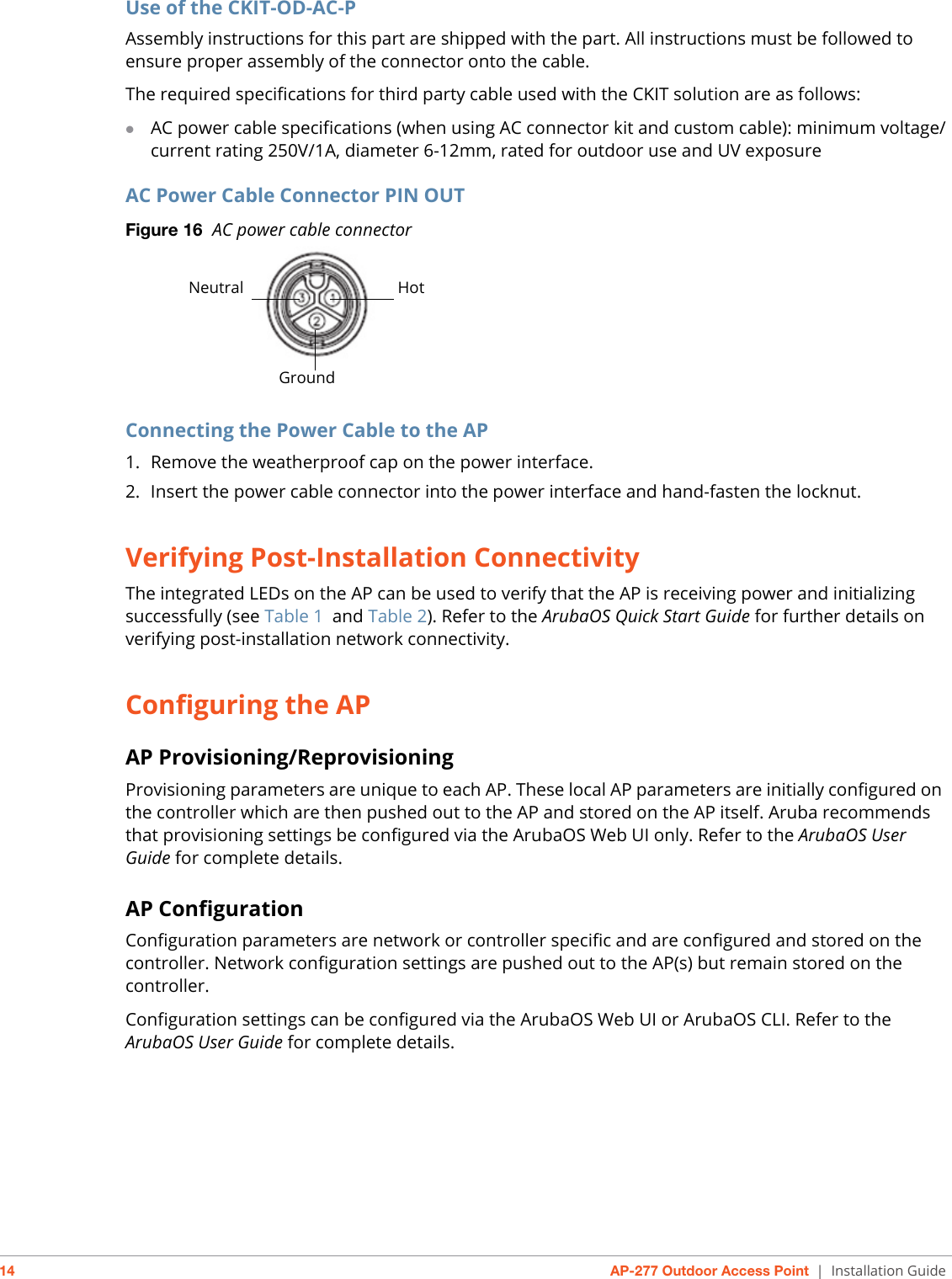
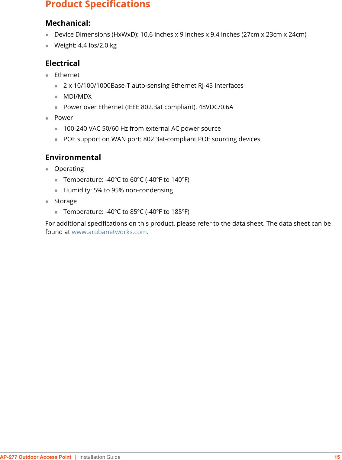
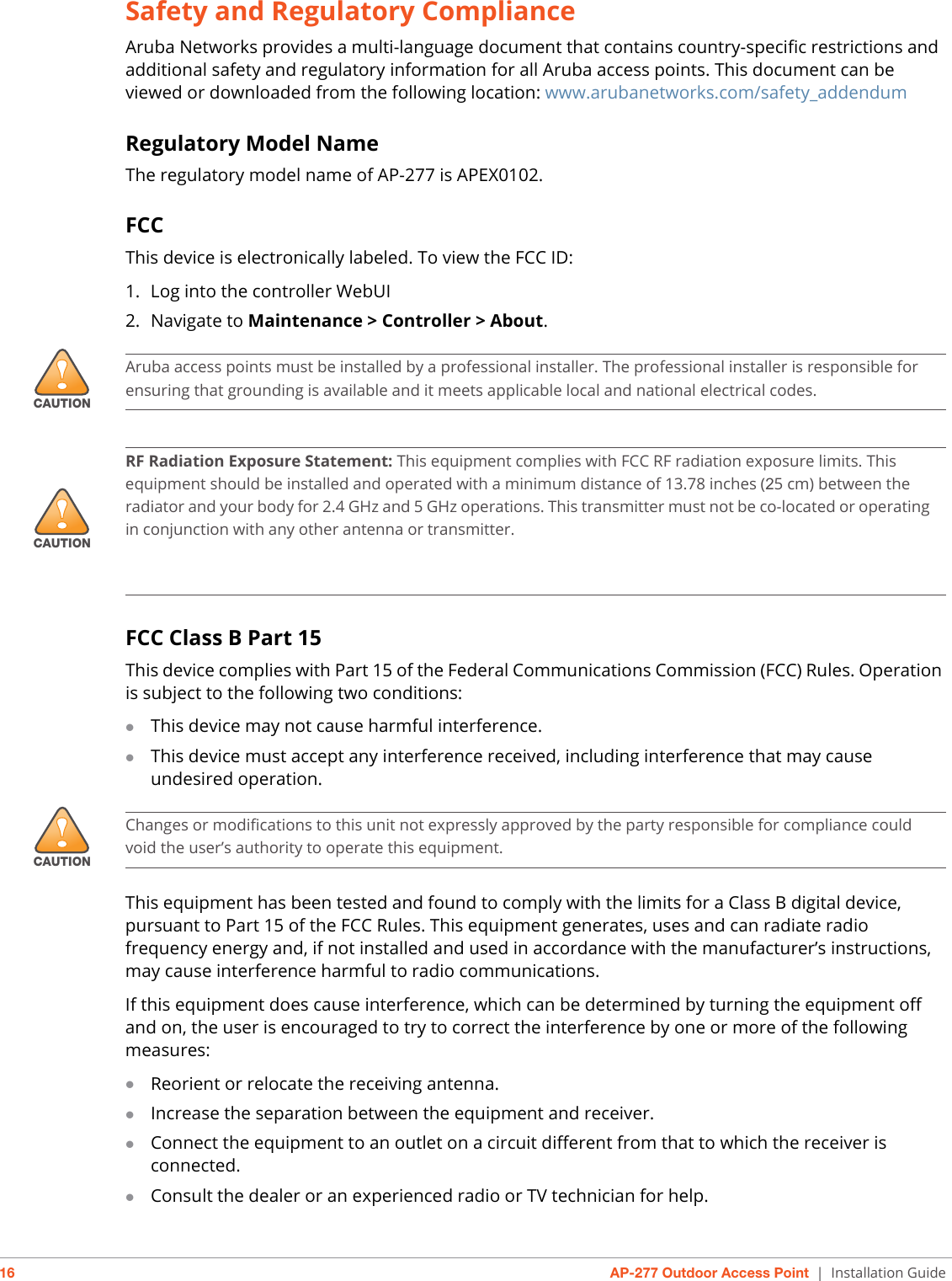
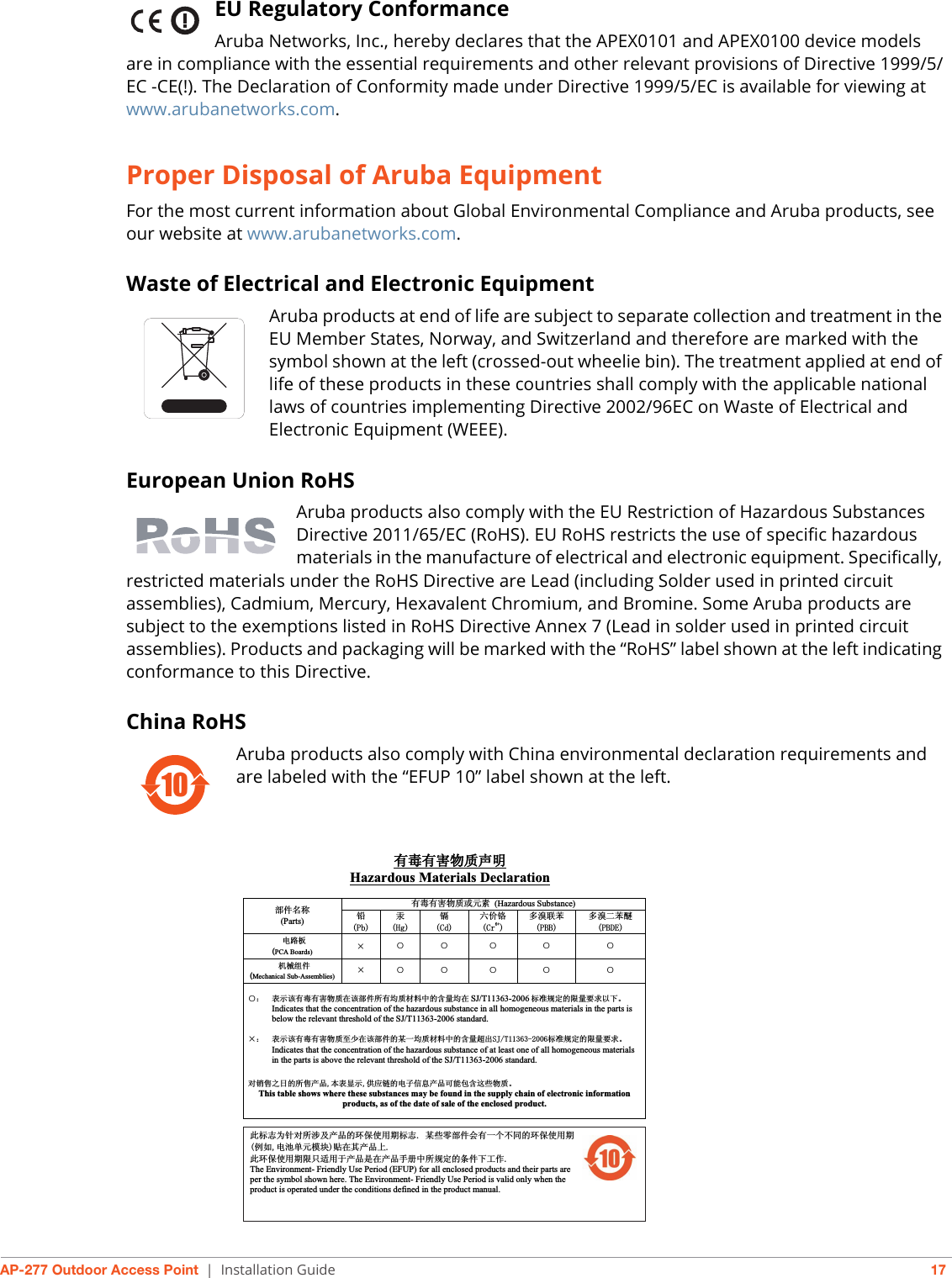
User Manual
TempConfidential_User Manual
Navigation menu
Upload a User Manual
Namespaces
Wiki Guide
HTML
PDF
Info
Views
User Manual
Discussion / Help
Navigation