Hewlett Packard Enterprise APIN0214215 Wireless Access Point User Manual Manual
Aruba Networks, Inc. Wireless Access Point Manual
UserManual.wiki
>
Hewlett Packard Enterprise
>
APIN0214215 User Manual
>
Manual
Contents
1.
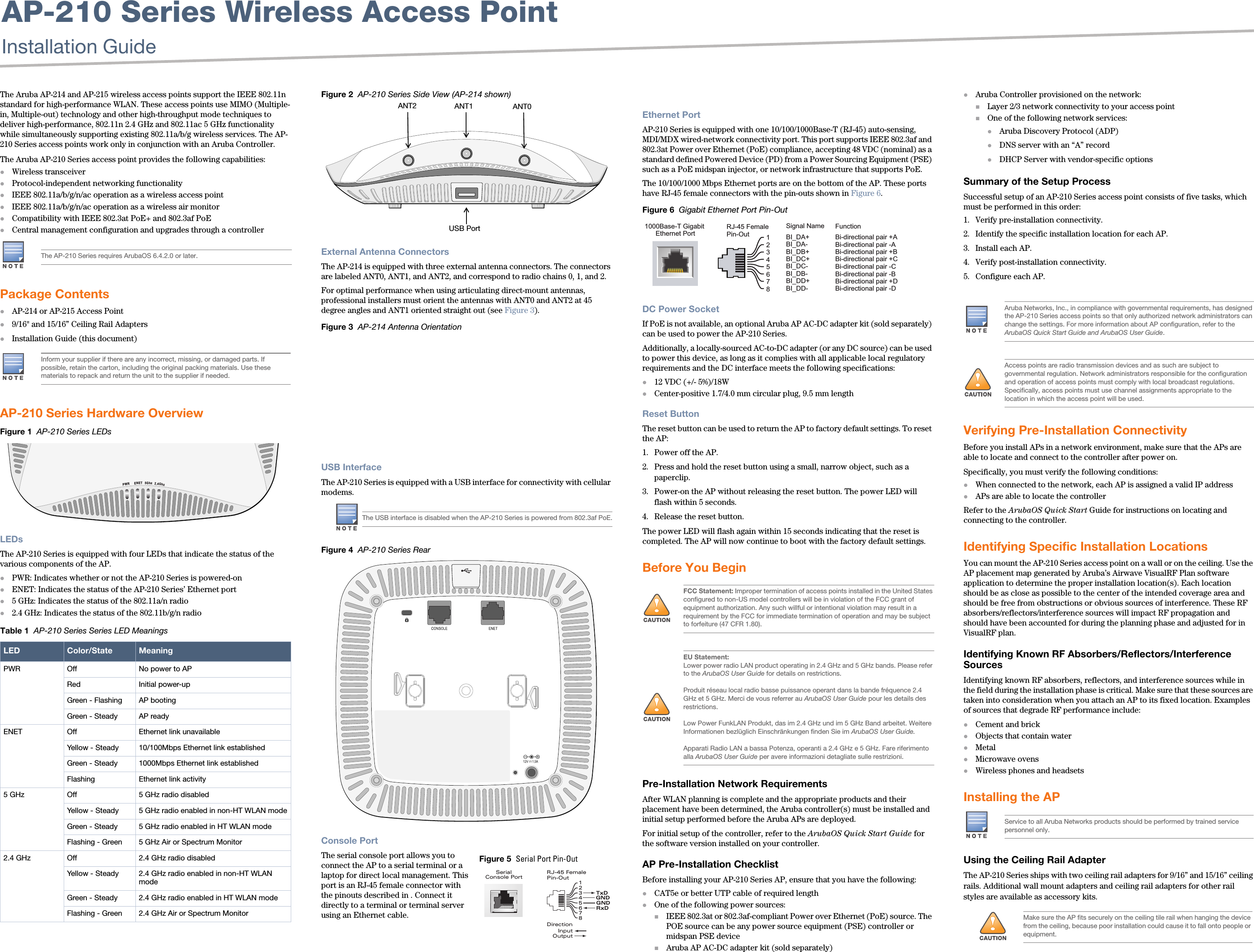
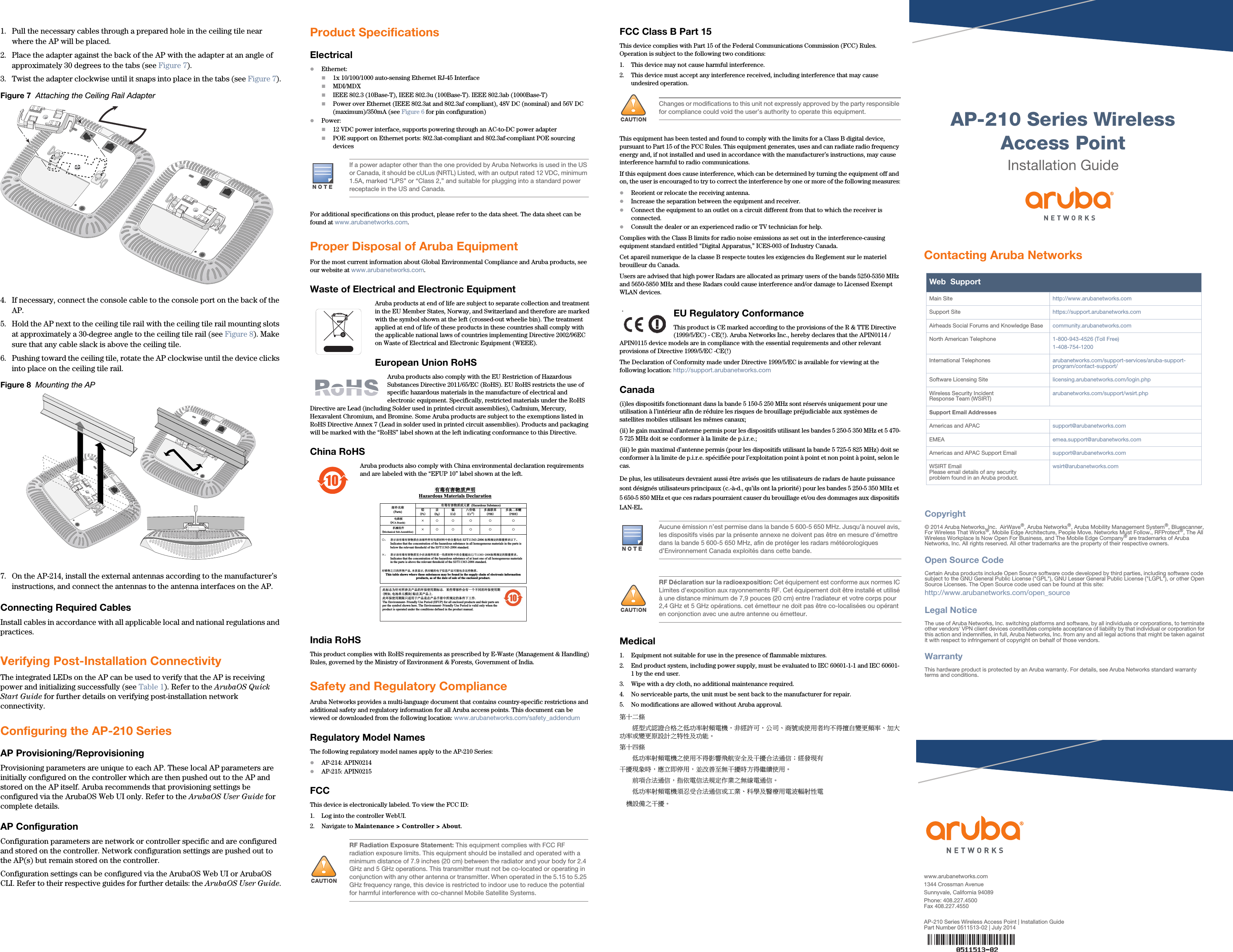
Manual
2.
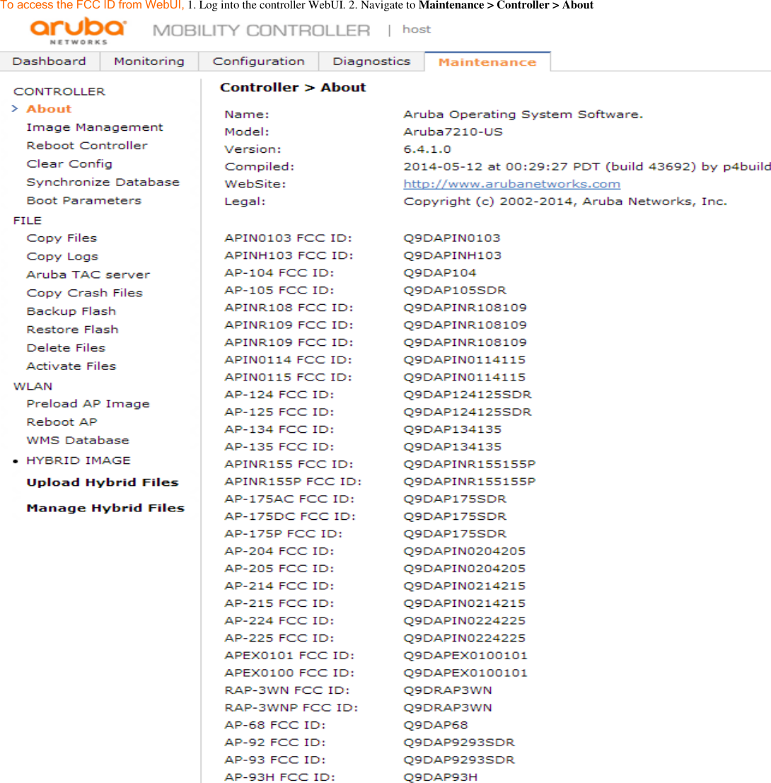
Revised Manual
Manual
Navigation menu
Upload a User Manual
Namespaces
Wiki Guide
HTML
PDF
Info
Views
User Manual
Discussion / Help
Navigation