Hewlett Packard Enterprise APIN0334335 Aruba 330 Series Wireless Access Point User Manual 0511873 03 xAP 33x IG
Aruba Networks, Inc. Aruba 330 Series Wireless Access Point 0511873 03 xAP 33x IG
Contents
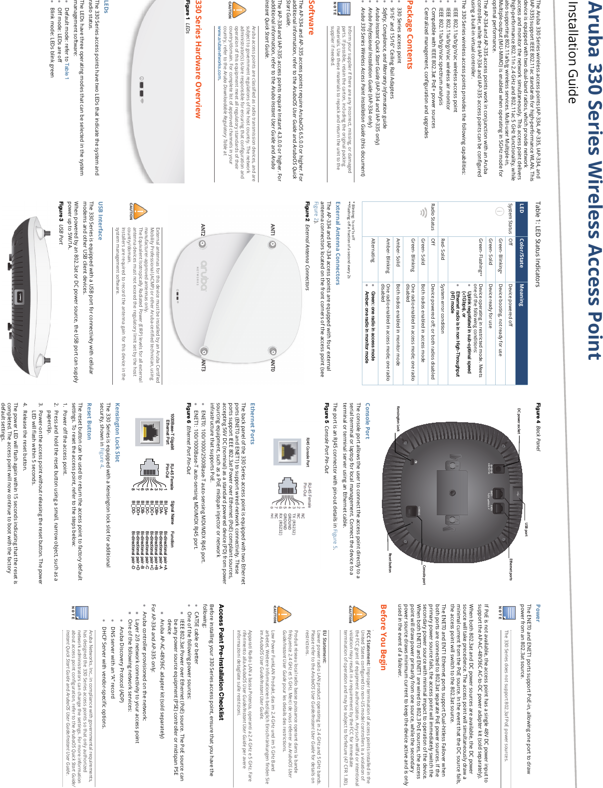
- 1. User Manual pt 1
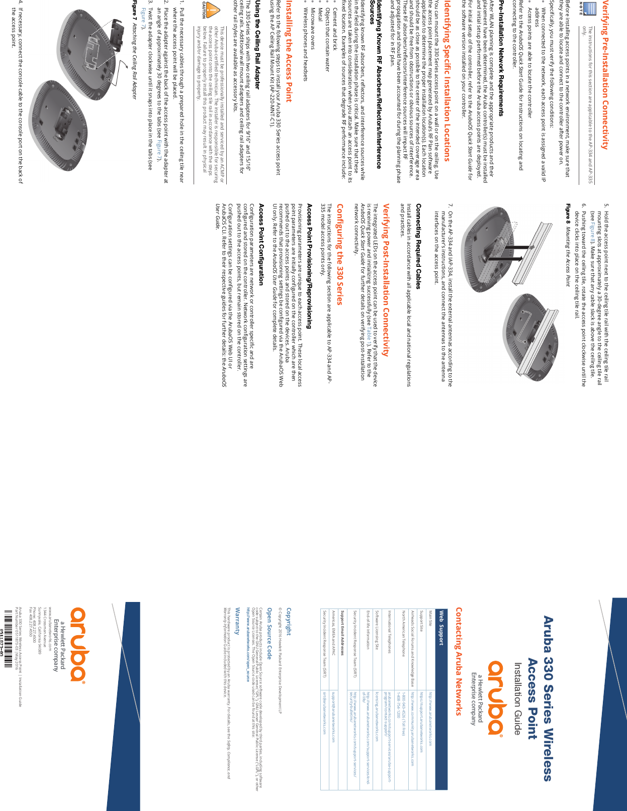
- 2. User Manual pt 2
User Manual pt 2