Hewlett Packard Enterprise APINH103 Wireless Access Point User Manual
Aruba Networks, Inc. Wireless Access Point
UserManual.wiki
>
Hewlett Packard Enterprise
>
APINH103 User Manual
>
5.User manual
Contents
1.
5.User manual
2.
Pages from ArubaOS 6.4 User Guide
3.
User manual_1
5.User manual
Navigation menu
Upload a User Manual
Namespaces
Wiki Guide
HTML
PDF
Info
Views
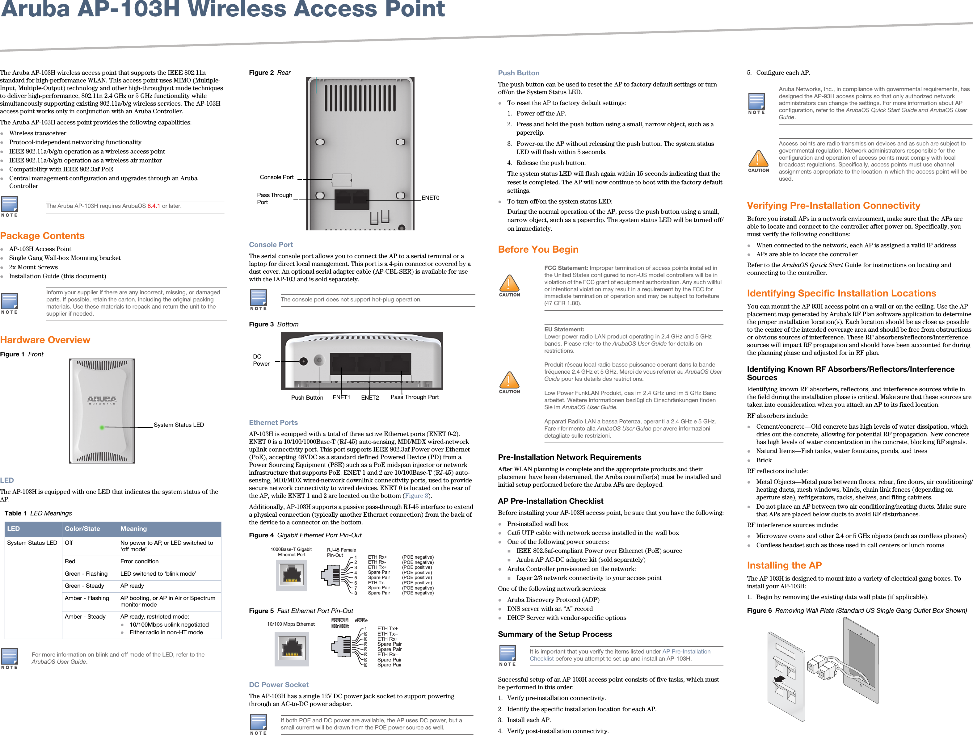
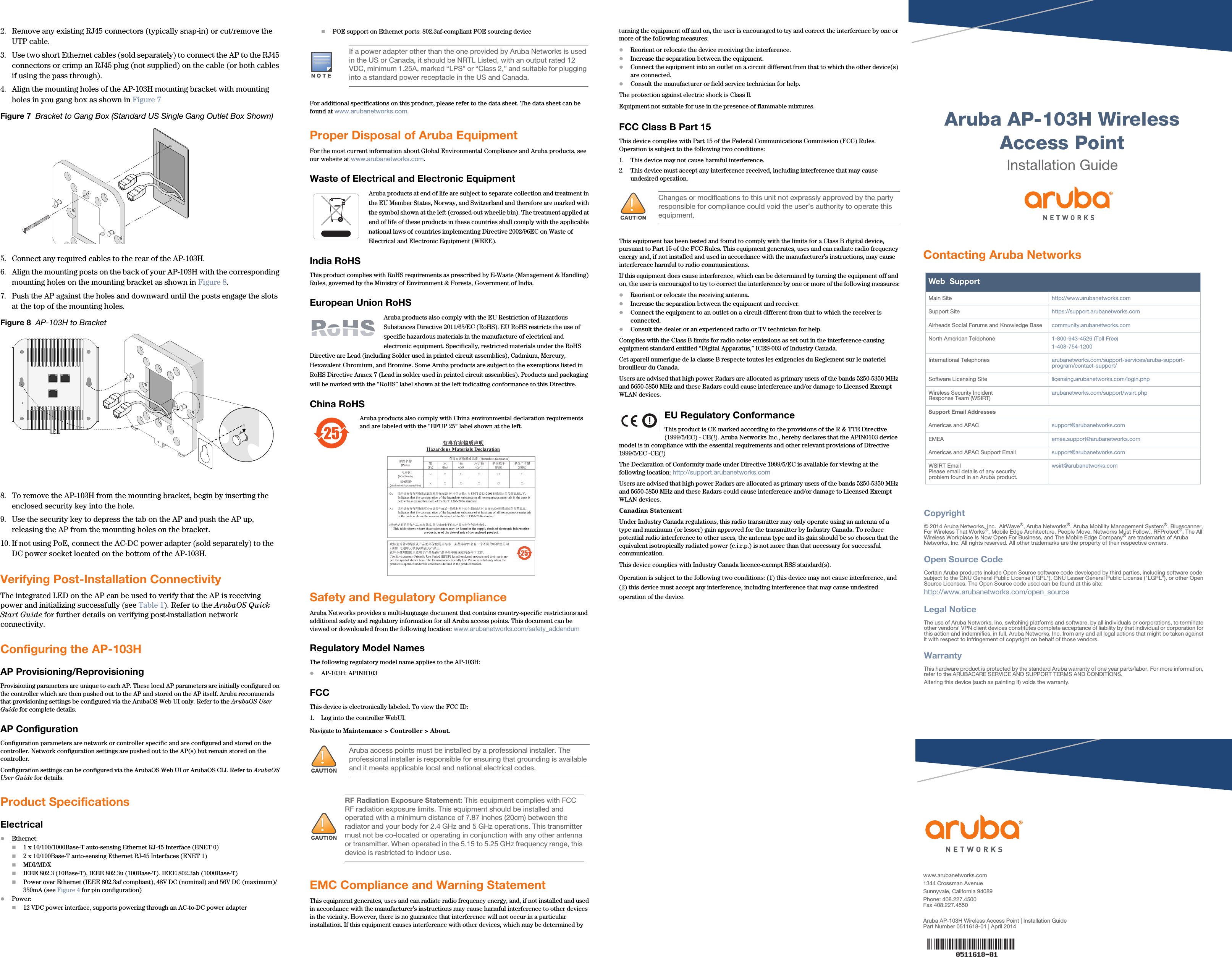
User Manual
Discussion / Help
Navigation