Hewlett Packard Enterprise ARUBA52 WLAN Dual Band Access Point User Manual
Aruba Networks, Inc. WLAN Dual Band Access Point
UserManual.wiki
>
Hewlett Packard Enterprise
>
ARUBA52 User Manual
Users Manual Revised
Navigation menu
Upload a User Manual
Namespaces
Wiki Guide
HTML
PDF
Info
Views
User Manual
Discussion / Help
Navigation

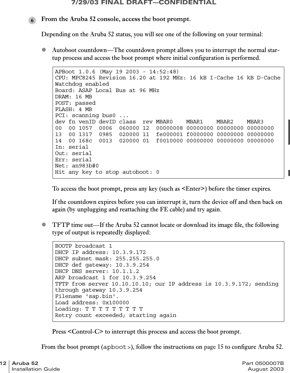
![7/29/03 FINAL DRAFT—CONFIDENTIALviii Aruba 52 Part 0500007BInstallation Guide August 2003Text ConventionsThe following conventions are used throughout this manual to emphasize important concepts:TABLE 1Text ConventionsType Style DescriptionItalics This style is used to emphasize important terms and to mark the titles of books.System items This fixed-width font depicts the following:zSample screen outputzSystem promptszFilenames, software devices, and certain commands when men-tioned in the text.Commands In the command examples, this bold font depicts text that the user must type exactly as shown.<Arguments> In the command examples, italicized text within angle brackets rep-resents items that the user should replace with information appropri-ate to their specific situation. For example:# send <text message>In this example, the user would type “send” at the system prompt exactly as shown, followed by the text of the message they wish to send. Do not type the angle brackets.[ Optional ] In the command examples, items enclosed in brackets are optional. Do not type the brackets.{ Item A | Item B } In the command examples, items within curled braces and separated by a vertical bar represent the available choices. Enter only one choice. Do not type the braces or bars.](https://usermanual.wiki/Hewlett-Packard-Enterprise/ARUBA52/User-Guide-363132-Page-8.png)
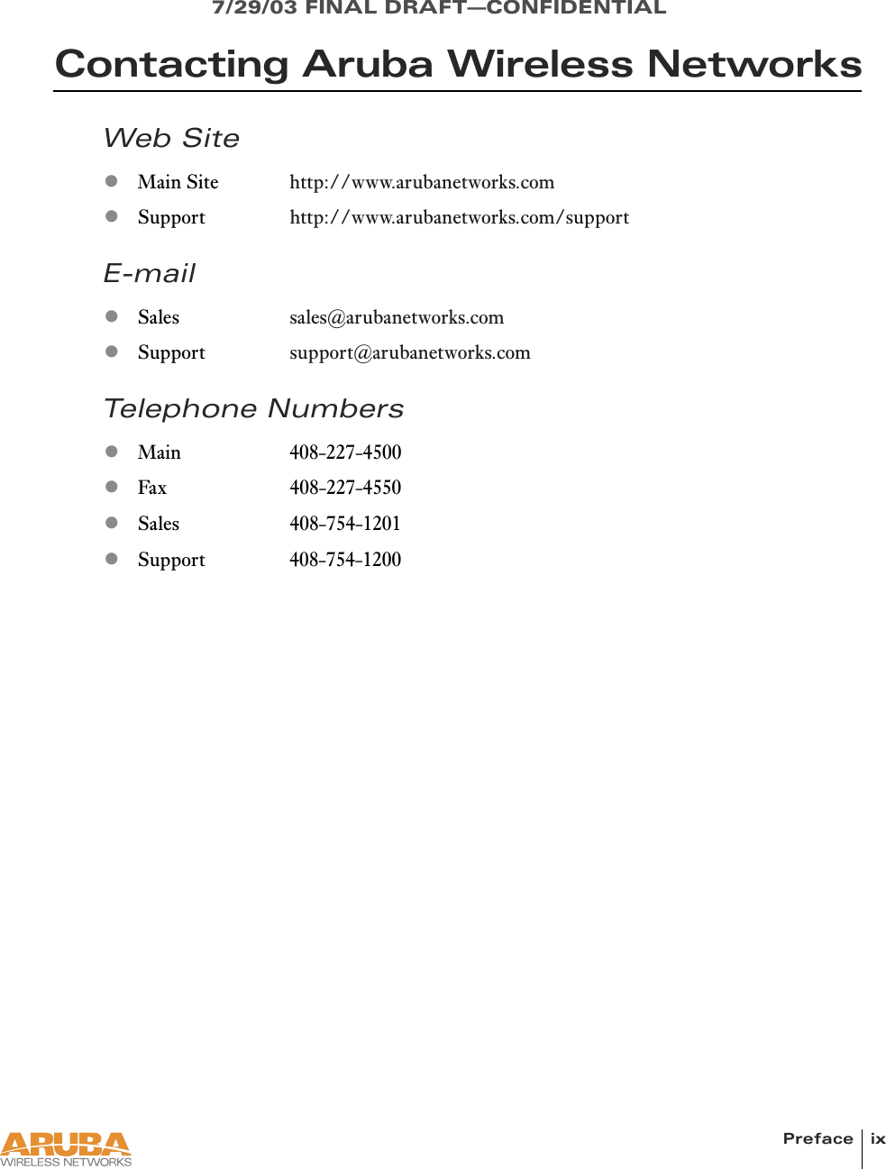

![Setup & Installation 11Chapter 27/29/03 FINAL DRAFT—CONFIDENTIALTelnet to the Aruba WLAN Switch Serial-Over-Ethernet (SOE) interface.Use a Telnet client on your management workstation to connect to theAruba WLAN Switch IP address using logical port 2300. The connection command may vary depending on the spe-cific software used, but commonly appears as follows:When prompted, log in to the Aruba WLAN Switch as the administrator:This will present you with the Aruba WLAN Switch SOE console prompt:Connect to the Aruba WLAN Switch port to which the Aruba 52 is physically attached:where slot number is the physical slot of the line card in the WLAN switch, and port number is the physical port.> telnet <switch IP address> 2300user: adminpassword: <administrator password (not displayed)>Available commands: baud [9600|19200|38400|57600|115200] connect <slot/port> exit (no args)soe>soe> connect <slot number>/<port number>345](https://usermanual.wiki/Hewlett-Packard-Enterprise/ARUBA52/User-Guide-363132-Page-21.png)