Hewlett Packard Enterprise ARUBA52 WLAN Dual Band Access Point User Manual
Aruba Networks, Inc. WLAN Dual Band Access Point
Users Manual Revised

7/29/03 FINAL DRAFT—CONFIDENTIAL
Aruba 52
Wireless Access Point
Installation Guide
TM
180 Great Oaks Blvd. Ste B
San Jose, California 95119
Net www.arubanetworks.com
Tel 408.227.4500
Fax 408.227.4550

7/29/03 FINAL DRAFT—CONFIDENTIAL
ii Aruba 52 Part 0500007B
Installation Guide August 2003
Copyright
Copyright © 2003 Aruba Wireless Networks, Inc. All rights reserved.
Specifications in this manual are subject to change without notice.
Originated in the USA.
Trademarks
Aruba 52, Aruba 5000, and AirOS are trademarks of Aruba Wireless Networks in the United States and
certain other countries.
The K & Lock design is a registered trademark of the Kensington Technology Group in the United States
and certain other countries.
Any other trademarks appearing in this manual are owned by their respective companies.

Aruba 52 iii
Installation Guide
7/29/03 FINAL DRAFT—CONFIDENTIAL
Compliance
FCC - Class B
This equipment has been tested and found to comply with the limits for a Class B digital device, pursuant
to Part 15 of the FCC Rules. These limits are designed to provide reasonable protection against harmful
interference in a residential installation. This equipment generates, uses and can radiate radio frequency
energy and, if not installed and used in accordance with instructions, may cause harmful interference to
radio communications. However, there is no guarantee that the interference will not occur in a particular
installation. If this equipment does cause harmful interference to radio or television reception, which can
be determined by turning the equipment off and on, the user is encouraged to try to correct the interfer-
ence by one or more of the following measures:
zReorient the receiving antenna
zIncrease the separation between the equipment and receiver
zConnect the equipment into an outlet on a circuit different from that to which the receiver is connected
zConsult the dealer or an experienced radio/TV technician for help
FCC Caution: To assure continued compliance, use only shielded interface cables when connecting to
computer or peripheral devices. Any changes or modifications not expressly approved by the party respon-
sible for compliance could void the user’s authority to operate this equipment.
This device complies with Part 15 of the FCC Rules. Operation is subject to the following two conditions:
(1) This device may not cause harmful interference, and (2) this device must accept any interference
received, including interference that may cause undesired operation.
CAUTION STATEMENT: FCC RF Radiation Exposure Statement
This equipment complies with FCC RF radiation exposure limits set forth for an uncontrolled environ-
ment. This equipment should be installed and operated with a minimum distance of 20 centimeters (8
inches) between the radiator and your body. This transmitter must not be co-located or operating in con-
junction with any other antenna or transmitter.
Radio Frequency Interference Requirements
This device is restricted to indoor use due to its operation in the 5.15 to 5.25 GHz frequency range. The
FCC requires this product to be used indoors to reduce the potential for harmful interference to co-chan-
nel Mobile Satellite systems. High power radars are allocated as primary users of the 5.25 to 5.35 GHz and
5.65 to 5.85 GHz bands. These radar stations can cause interference with and/or damage this device.
Industry Canada - Class B
This digital apparatus does not exceed the Class B limits for radio noise emissions from digital apparatus as
set out in the interference-causing equipment standard entitled “Digital Apparatus,” ICES-003 of the
Department of Communications.
Cet appareil numérique respecte les limites de bruits radioélectriques applicables aux appareils numériques
de Classe B prescrites dans la norme sur le matériel brouilleur: “Appareils Numériques,” NMB-003 édictée
par le ministère des Communications.

7/29/03 FINAL DRAFT—CONFIDENTIAL
iv Aruba 52 Part 0500007B
Installation Guide August 2003

Contents v
7/29/03 FINAL DRAFT—CONFIDENTIAL
Contents
Preface . . . . . . . . . . . . . . . . . . . . . . vii
Related Documents. . . . . . . . . . . . . . . . . . vii
Text Conventions . . . . . . . . . . . . . . . . . . viii
Contacting Aruba Wireless Networks . . . . . . . . . . ix
Chapter 1 Introduction . . . . . . . . . . . . . . . . . . . 1
Product Features . . . . . . . . . . . . . . . . . . . . 1
Ethernet Compatibility . . . . . . . . . . . . . . . 2
Radio Characteristics . . . . . . . . . . . . . . . . 2
Power Over Ethernet . . . . . . . . . . . . . . . . 2
Physical Description . . . . . . . . . . . . . . . . . . 3
Package Checklist . . . . . . . . . . . . . . . . . 3
Top Panel . . . . . . . . . . . . . . . . . . . . . 4
Rear Panel . . . . . . . . . . . . . . . . . . . . . 6
Chapter 2 Setup & Installation . . . . . . . . . . . . . 7
Requirements . . . . . . . . . . . . . . . . . . . . . 7
Select a Network Topology . . . . . . . . . . . . . . . 8
Perform Initial Setup . . . . . . . . . . . . . . . . . . 10
Direct SPOE to the Aruba WLAN Switch . . . . . 10
Direct Terminal Connection . . . . . . . . . . . . 13
Configure the Aruba 52. . . . . . . . . . . . . . . 15
Mount the Aruba 52 . . . . . . . . . . . . . . . . . . 18
Free-Standing Placement . . . . . . . . . . . . . . 19
Using the Built-In Mounting Slots . . . . . . . . . 19
Using the Optional Mounting Kit. . . . . . . . . . 21

7/29/03 FINAL DRAFT—CONFIDENTIAL
vi Aruba 52 Part 0500007B
Installation Guide August 2003
Connect Required Cables . . . . . . . . . . . . . . . . 25
Direct SPOE to the Aruba WLAN Switch . . . . . 25
LAN or POE Connection. . . . . . . . . . . . . . 26
Appendix A Port Specifications . . . . . . . . . . . . . 29
Console Port . . . . . . . . . . . . . . . . . . . . . . 29
FE Port . . . . . . . . . . . . . . . . . . . . . . . . 30
SPOE Adapter . . . . . . . . . . . . . . . . . . . . . 31
Appendix B Product Specifications . . . . . . . . . . 33

Preface vii
7/29/03 FINAL DRAFT—CONFIDENTIAL
Preface
The preface includes the following information:
zA list of related documentation for further reading
zA key to the various text conventions used throughout this manual
zAruba Wireless Networks support and service information
Related Documents
The following items are part of the complete documentation for the Aruba system:
zAruba 5000 Installation Guide (Part No. 0500001A, June 2003)
zAruba AirOS v1.1 User’s Guide (Part No. 0500002B, August 2003)
zAruba 52 Installation Guide (Part No. 0500007B, August 2003)

7/29/03 FINAL DRAFT—CONFIDENTIAL
viii Aruba 52 Part 0500007B
Installation Guide August 2003
Text Conventions
The following conventions are used throughout this manual to emphasize important concepts:
TABLE 1Text Conventions
Type Style Description
Italics This style is used to emphasize important terms and to mark the
titles of books.
System items This fixed-width font depicts the following:
zSample screen output
zSystem prompts
zFilenames, software devices, and certain commands when men-
tioned in the text.
Commands In the command examples, this bold font depicts text that the user
must type exactly as shown.
<Arguments> In the command examples, italicized text within angle brackets rep-
resents items that the user should replace with information appropri-
ate to their specific situation. For example:
# send <text message>
In this example, the user would type “send” at the system prompt
exactly as shown, followed by the text of the message they wish to
send. Do not type the angle brackets.
[ Optional ] In the command examples, items enclosed in brackets are optional.
Do not type the brackets.
{ Item A | Item B } In the command examples, items within curled braces and separated
by a vertical bar represent the available choices. Enter only one
choice. Do not type the braces or bars.

Preface ix
7/29/03 FINAL DRAFT—CONFIDENTIAL
Contacting Aruba Wireless Networks
Web Site
E-mail
Telephone Numbers
zMain Site http://www.arubanetworks.com
zSupport http://www.arubanetworks.com/support
zSales sales@arubanetworks.com
zSupport support@arubanetworks.com
zMain 408-227-4500
zFax 408-227-4550
zSales 408-754-1201
zSupport 408-754-1200

7/29/03 FINAL DRAFT—CONFIDENTIAL
xAruba52 Part 0500007B
Installation Guide August 2003

Introduction 1
Chapter 1
7/29/03 FINAL DRAFT—CONFIDENTIAL
CHAPTER 1
Introduction
The Aruba 52 is part of a comprehensive wireless network solution. The device works in con-
junction with the Aruba 5000 WLAN Switch and can act as a wireless access point or air mon-
itor.
As a wireless access point, the Aruba 52 provides transparent, secure, high-speed data com-
munications between wireless network devices (fixed, portable, or mobile computers with
IEEE 802.11a, 802.11b, or 802.11g wireless adapters) and the wired LAN.
As a wireless air monitor, a uniquely Aruba feature, the Aruba 52 enhances wireless networks
by collecting statistics, monitoring traffic, detecting intrusions, enforcing security policies,
balancing wireless traffic load, self-healing coverage gaps, and more.
Product Features
zWireless dual-band transceiver
zDual, omnidirectional antennas for reception diversity
zProtocol-independent networking functionality
z802.11a – up to 54 Mbps data rate per channel: offers a high data rate and reliable wireless
connectivity
z802.11b – up to 11 Mbps data rate per channel: provides an alternative to wired LANs that
can dramatically cut costs
z802.11g – up to 54 Mbps data rate per channel: backwards compatible with 802.11b
zCompatible with IEEE 802.3af Power Over Ethernet (POE)
zSeamless connectivity to wired LANs augment existing networks quickly and easily
zCan be centrally managed, configured, and upgraded through the Aruba WLAN Switch
to take advantage of network changes and security improvements

7/29/03 FINAL DRAFT—CONFIDENTIAL
2Aruba52 Part 0500007B
Installation Guide August 2003
Ethernet Compatibility
The Aruba 52 attaches to 10/100 Mbps Ethernet (FE) LAN segments that utilize
10Base-T/100Base-TX (twisted-pair) wiring. The device appears as an Ethernet node and
performs a routing function by moving packets between the wired LAN and remote worksta-
tions on the wireless infrastructure.
Radio Characteristics
For IEEE 802.11a operation, the Aruba 52 uses a radio modulation technique known as
Orthogonal Frequency Division Multiplexing (OFDM), and a shared collision domain
(CSMA/CA). It operates in the 5GHz Unlicensed National Information Infrastructure
(UNII) band. Data is transmitted over a half-duplex radio channel operating at up to 54
Megabits per second (Mbps).
For IEEE 802.11b operation, the Aruba 52 uses the IEEE 802.11 High-Rate Direct Sequence
(HRDS) specification, and a shared collision domain (CSMA/CA). It operates in the 2.4GHz
Industrial/Scientific/Medical (ISM) band. The ISM band is available worldwide for unli-
censed use. Data is transmitted at speeds of up to 11 Mbps.
For IEEE 802.11g operation, the Aruba 52 uses ODFM and a shared collision domain
(CSMA/CA). It operates in the 2.4GHz Industrial/Scientific/Medical (ISM) band. The
ISM band is available worldwide for unlicensed use. Data is transmitted at speeds of up to 54
Mbps.
Power Over Ethernet
The Aruba 52 supports the IEEE 802.3af standard for Power Over Ethernet (POE). With this
feature, the Aruba 52 can accept electrical power from a compatible POE-capable device to
which it is connected, directly over the FE cable. POE eliminates the need to provide separate
power outlets in environments that are difficult or undesirable to wire for electricity.
The Aruba 52 supports POE only when the FE port is connected to an IEEE 802.3af compli-
ant device (such as the Aruba 5000 WS-5032 Line Card).
Introduction 3
Chapter 1
7/29/03 FINAL DRAFT—CONFIDENTIAL
Physical Description
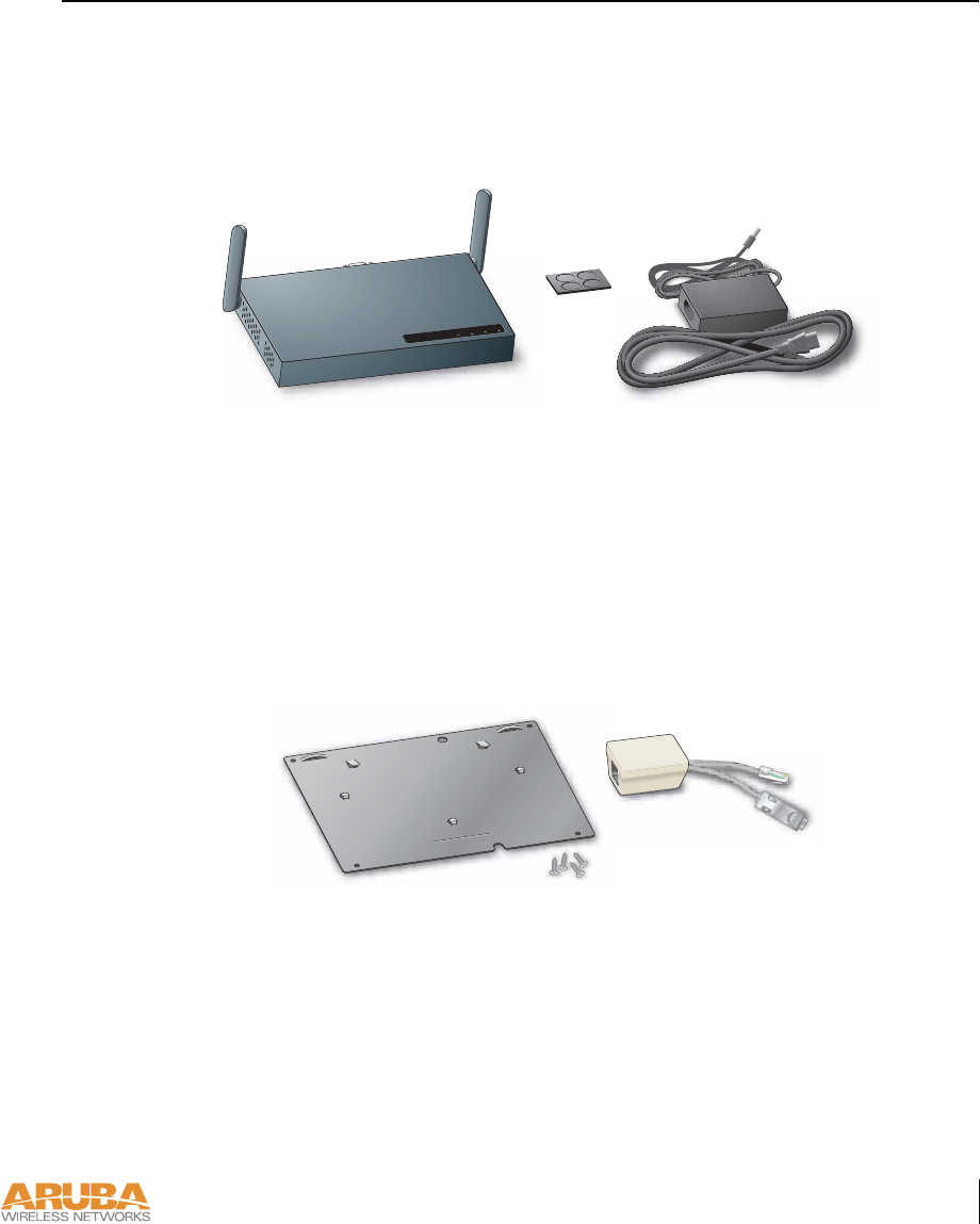
Package Checklist
The Aruba 52 package includes:
FIGURE 1-1 Package Contents
zOne Aruba 52 Wireless Access Point
zNon-slip rubber foot-pads
zOne AC power adapter (3.3 VDC, 4 A) and power cord
zAssorted documentation
The following optional items can also be ordered for the Aruba 52:
FIGURE 1-2 Optional Items
zMounting kit: cradle and screws
zSerial & Power Over Ethernet (SPOE) adapter
Inform your supplier if there are any incorrect, missing or damaged parts. If possible, retain
the carton, including the original packing materials. Use them again to repack the product in
case there is a need to return it.
READYLAN.A.B
7/29/03 FINAL DRAFT—CONFIDENTIAL
4Aruba52 Part 0500007B
Installation Guide August 2003
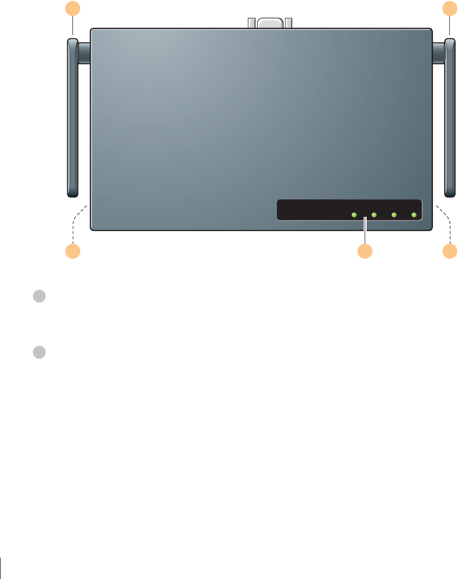
To p Pa n e l
FIGURE 1-3 Aruba 52 Top Panel
Dual, omnidirectional Antennas for Wireless Communications (on sides)
The antennas swivel and should be oriented vertically (straight up and down) away from the
chassis for best performance.
Air Vents (on sides)
These vents promote proper air circulation for cooling the device. Do not allow these vents to
be obstructed by mounting equipment, network cables, or any other material.
READY LAN .A .B/.G
1 1
2 23
1
2
Introduction 5
Chapter 1
7/29/03 FINAL DRAFT—CONFIDENTIAL
Indicator LEDs
During operation, the Aruba 52 LEDs provide the following information:
NOTE—LEDs on the Aruba WLAN Switch provide additional status and security informa-
tion about connected APs. See the Aruba 5000 Installation Guide and Aruba AirOS User’s
Guide for more information.
TABLE 1-1 Aruba 52 LEDs
LED State Description
Ready Off The device is off or initializing.
Green The device has passed self-test and is operating.
Flashing The device is running a self-test or loading new software. If the
condition persists for more than one minute, refer to the trou-
bleshooting information in Appendix A.
LAN Off No link on the FE port on back of the device.
Green Link detected on the FE port.
Flashing Transmitting or receiving data across the FE port. Flashing
rate is proportional to your network activity.
.A Off The 802.11a wireless interface is disabled or down.
Green The device is operating as an 802.11a access point.
Flashing The device is operating as an 802.11a air monitor.
.B/.G Off The 802.11b/g wireless interface is disabled or down.
Green The device is operating as an 802.11b/g access point.
Flashing The device is operating as an 802.11b/g air monitor.
3
7/29/03 FINAL DRAFT—CONFIDENTIAL
6Aruba52 Part 0500007B
Installation Guide August 2003
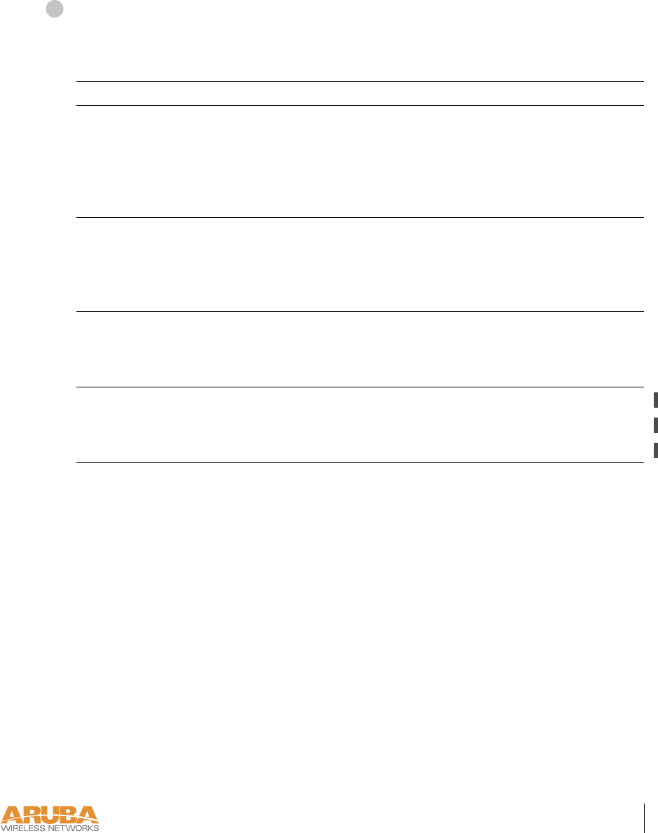
Rear Panel
FIGURE 1-4 Aruba 52 Rear Panel
Kensington Security Slot
This slot is compatible with a Kensington MicroSaver Security Cable (not included) which
can be used to prevent the unauthorized removal of the Aruba 52 from its installed location.
To secure the Aruba 52, wrap a security cable around an immovable object, insert the cable’s
lock into the Kensington Security Slot, and turn the key.
Console Port
This port has a 9-pin, female serial connector. It is used primarily to connect a terminal during
initial setup of the Aruba 52. See Appendix A for port details.
Using the optional SPOE adapter, this port can also be connected directly to an FE port on an
Aruba WLAN Switch that supports SPOE (see “Power Over Ethernet” on page 2). This
direct connection provides extra maintenance options during normal operation.
FE Port
This port attaches the Aruba 52 to 10Base-T/100Base-TX (twisted-pair) Ethernet LAN seg-
ments. The port automatically adjusts MDI/MDX to accept either straight-through or cross-
over cables. See Appendix A for port details.
This port also supports POE (see “Power Over Ethernet” on page 2). When POE is used, a
straight-through cable is required.
DC Power Socket
This socket is used to connect the included AC power adapter. If POE is being used to supply
power to the Aruba 52, the power adapter is not necessary.
Mounting Slots (on bottom)
The keyhole-shaped slots on the bottom of the chassis are used for mounting the Aruba 52.
1 2 3 4 5
®
1
2
3
4
5

Setup & Installation 7
Chapter 2
7/29/03 FINAL DRAFT—CONFIDENTIAL
CHAPTER 2
Setup & Installation
This chapter covers the following topics:
zRequirements for installing the Aruba 52
zSupported network topology options
zInitial setup of the Aruba 52
zPhysical mounting of the device
zConnecting the required cables
zTesting the installation
Requirements
Before you install the Aruba 52, you must have the following:
zAn operational Aruba WLAN Switch with a valid IP route to the LAN segment to which
the access point or air monitor will be connected.
zAn appropriate physical location for the new access point or air monitor.
We recommend an up-to-date site survey to help determine the optimal location for your
Aruba 52. See your Aruba AirOS Software Guide for instructions on using the Aruba
WLAN Switch’s built-in planning tools.
zClient devices with IEEE 802.11a, 802.11b, or 802.11g compliant wireless Ethernet
adapters with TCP/IP compatible protocol installed.
zOne of the following power sources for the access point or air monitor:
zAn AC power outlet rated at 100~240 V, 50~60 Hz.
zPower Over Ethernet (POE) capability on the device to which the Aruba 52 is con-
nected (see “Power Over Ethernet” on page 2).
NOTE—When installing the Aruba 52 in plenums or air-handling spaces, as described in
NEC (2002) Article 300.22(C), the device must be powered using POE, and not the
included AC power adapter.
7/29/03 FINAL DRAFT—CONFIDENTIAL
8Aruba52 Part 0500007B
Installation Guide August 2003
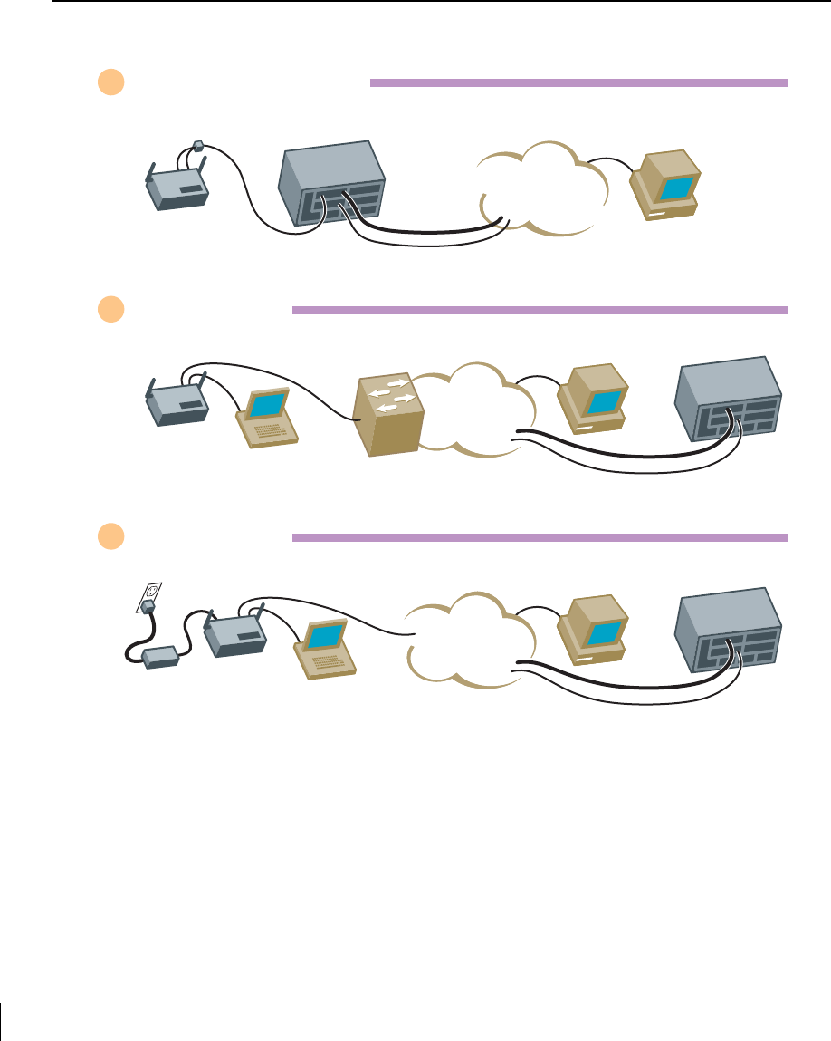
Select a Network Topology
The Aruba 52 can be installed in your network using the following topologies:
FIGURE 2-1 Aruba 52 Topology Options
1Direct SPOE Installation
2POE Installation
3LAN Installation
LAN Switch
w/POE
Power & Ethernet
Data Network
Mgmt. Network
Aruba 50
Serial Console
(Initial Setup Only)
LAN
Management
Workstation Aruba 5000
Ethernet
Aruba 50
Serial Console
(Initial Setup Only)
LAN
Power
Adapter
Data Network
M
g
mt. Network
Management
Workstation Aruba 5000
Aruba 5000
w/SPOE
Serial, Power
& Ethernet
Data Network
Mgmt. Network
Aruba 50
LAN
Management
Workstation

Setup & Installation 9
Chapter 2
7/29/03 FINAL DRAFT—CONFIDENTIAL
Direct Serial & Power Over Ethernet (SPOE) to the Aruba WLAN Switch (recom-
mended)
In this topology, both the console and 10/100 Mbps Ethernet (FE) ports on the Aruba 52 are
connected to the SPOE adapter. An 8-conductor, Category 5 UTP, straight-through FE cable
connects the adapter directly to the Aruba WLAN Switch with no intervening hubs, routers,
or other network equipment. The network port on the Aruba WLAN Switch must include
optional SPOE capability (see “Power Over Ethernet” on page 2).
This topology provides the following features:
z10/100 Mbps Ethernet connectivity
zElectrical power through the FE cable
zSerial console connectivity through the FE cable
zExtra console maintenance options during normal operation
POE connection through the LAN
In this topology, the Aruba 52 is connected to the LAN through a hub or switch that is POE
compatible (see “Power Over Ethernet” on page 2). An 8- or 4-conductor, Category 5 UTP,
straight-through FE cable is required. Initial setup requires a local serial console.
This topology provides the following features:
z10/100 Mbps Ethernet connectivity (depending on the connecting port)
zElectrical power through the FE cable
zVersatile placement of the Aruba WLAN Switch and Aruba 52s within the network
Connection to a non-POE network port on the Aruba WLAN Switch or other net-
work device
In this topology, the Aruba 52 is connected to the Aruba WLAN Switch either directly or
through the LAN. An 8- or 4-conductor, Category 5 UTP, straight-through or crossover FE
cable may be used. Initial setup requires a local serial console. Electrical power is supplied
using the included AC power adapter.
This topology provides the following features:
z10/100 Mbps Ethernet connectivity (depending on the connecting port)
zVersatile placement of the Aruba WLAN Switch and Aruba 52s within the network
1
2
3
7/29/03 FINAL DRAFT—CONFIDENTIAL
10 Aruba 52 Part 0500007B
Installation Guide August 2003
Perform Initial Setup
The Aruba 52 requires some initial configuration before it will operate. The method used for
connecting to the Aruba 52 for initial setup depends on your intended network topology (see
Figure 2-1 on page 8).
Direct SPOE to the Aruba WLAN Switch
Use this procedure when connecting the Aruba 52 directly to an SPOE-compatible network
port on the Aruba WLAN Switch (see “Power Over Ethernet” on page 2). SPOE provides
10/100 Mbps Ethernet, serial connection, and power over one cable.
NOTE—If connecting the Aruba 52 through the LAN or to a non-SPOE network port on
the Aruba WLAN Switch, see the instructions on page 13.
Connect the SPOE adapter to the Aruba 52.
Connect the adapter’s 9-pin serial connector to the Console port on the back of the
Aruba 52.
Connect the adapter’s male RJ-45 plug to the FE port on the back of the Aruba 52.
Connect the Aruba 52 to the Aruba WLAN Switch.
The connection between the Aruba 52 and the Aruba WLAN Switch requires an 8-conduc-
tor, Category 5 UTP, straight-through FE cable with RJ-45 connectors (see Appendix A for
port specifications).
Connect one end of the FE cable directly to the RJ-45 socket on the SPOE adapter that
was attached to the Aruba 52 in the previous step.
Connect the other end of the FE cable directly to an available SPOE network port on the
Aruba WLAN Switch.
NOTE—The Aruba 52 must be connected to the Aruba WLAN Switch without any inter-
vening hubs, routers, or other networking equipment.
1
A
B
2
CAUTION—To prevent personal injury or damage to equipment, be sure to com-
ply with electrical grounding standards during all phases of installation and operation
of the AP. Do not allow theAruba 52 to contact metal which is connected a different
electrical ground than the Aruba WLAN Switch. Also, never connect the AP or
WLAN switch to external storm grounding sources.
A
B
Setup & Installation 11
Chapter 2
7/29/03 FINAL DRAFT—CONFIDENTIAL
Telnet to the Aruba WLAN Switch Serial-Over-Ethernet (SOE) interface.
Use a Telnet client on your management workstation to connect to theAruba WLAN Switch
IP address using logical port 2300. The connection command may vary depending on the spe-
cific software used, but commonly appears as follows:
When prompted, log in to the Aruba WLAN Switch as the administrator:
This will present you with the Aruba WLAN Switch SOE console prompt:
Connect to the Aruba WLAN Switch port to which the Aruba 52 is physically
attached:
where slot number is the physical slot of the line card in the WLAN switch, and port number is
the physical port.
>
telnet
<switch IP address>
2300
user: admin
password:
<administrator password (not displayed)>
Available commands:
baud [9600|19200|38400|57600|115200]
connect <slot/port>
exit (no args)
soe>
soe>
connect <slot number>/<port number>
3
4
5
7/29/03 FINAL DRAFT—CONFIDENTIAL
12 Aruba 52 Part 0500007B
Installation Guide August 2003
From the Aruba 52 console, access the boot prompt.
Depending on the Aruba 52 status, you will see one of the following on your terminal:
zAutoboot countdown—The countdown prompt allows you to interrupt the normal star-
tup process and access the boot prompt where initial configuration is performed.
To access the boot prompt, press any key (such as <Enter>) before the timer expires.
If the countdown expires before you can interrupt it, turn the device off and then back on
again (by unplugging and reattaching the FE cable) and try again.
zTFTP time out—If the Aruba 52 cannot locate or download its image file, the following
type of output is repeatedly displayed:
Press <Control-C> to interrupt this process and access the boot prompt.
From the boot prompt (apboot>), follow the instructions on page 15 to configure Aruba 52.
APBoot 1.0.6 (May 19 2003 - 14:52:48)
CPU: MPC8245 Revision 16.20 at 192 MHz: 16 kB I-Cache 16 kB D-Cache
Watchdog enabled
Board: ASAP Local Bus at 96 MHz
DRAM: 16 MB
POST: passed
FLASH: 4 MB
PCI: scanning bus0 ...
dev fn venID devID class rev MBAR0 MBAR1 MBAR2 MBAR3
00 00 1057 0006 060000 12 00000008 00000000 00000000 00000000
13 00 1317 0985 020000 11 fe000001 f0000000 00000000 00000000
14 00 168c 0013 020000 01 f0010000 00000000 00000000 00000000
In: serial
Out: serial
Err: serial
Net: an983b#0
Hit any key to stop autoboot: 0
BOOTP broadcast 1
DHCP IP address: 10.3.9.172
DHCP subnet mask: 255.255.255.0
DHCP def gateway: 10.3.9.254
DHCP DNS server: 10.1.1.2
ARP broadcast 1 for 10.3.9.254
TFTP from server 10.10.10.10; our IP address is 10.3.9.172; sending
through gateway 10.3.9.254
Filename 'sap.bin'.
Load address: 0x100000
Loading: T T T T T T T T T
Retry count exceeded; starting again
6
Setup & Installation 13
Chapter 2
7/29/03 FINAL DRAFT—CONFIDENTIAL
Direct Terminal Connection
Use this procedure when connecting the Aruba 52 through the LAN or to a non-SPOE net-
work port on the Aruba WLAN Switch. Under these topologies, a direct terminal connection
is required for initial setup.
NOTE—If connecting the Aruba 52 directly to a SPOE network port on the Aruba WLAN
Switch, see the instructions on page 10.
Connect power to the Aruba 52.
The Aruba 52 can receive electrical power using the following options:
zPOE–If connecting the Aruba 52 to a device that supplies IEEE 802.3af compliant POE
(see “Power Over Ethernet” on page 2), no additional power connection is necessary.
zPower Outlet
NOTE—When the Aruba 52 is installed in an air-handling space, as described in NEC
(2002) Article 300.22(C), POE must be used instead of a power outlet.
If local regulations and practices permit, connect the included AC power adapter cable to
the DC power socket on the rear panel of the Aruba 52 and plug it into an appropriate
power outlet.
NOTE—The indicator LEDs on top of the Aruba 52 will remain dark during this procedure.
CAUTION—Be sure to comply with electrical grounding standards during all
phases of installation and operation of the AP. Do not allow the Aruba 52 or power
adapter (if used) to be connected to or make contact with metal or power outlets on a
different electrical ground than the device to which it is connected. Also, never con-
nect the AP to external storm grounding sources.
CAUTION—To prevent personal injury or damage to equipment, use only the
AC power adapter supplied with this device.
1
7/29/03 FINAL DRAFT—CONFIDENTIAL
14 Aruba 52 Part 0500007B
Installation Guide August 2003
Set up your local terminal.
This procedure requires a terminal or computer running terminal emulation software with the
following settings:
Connect the terminal directly to the Aruba 52.
Use a standard serial cable to connect the Aruba 52 console port to a serial port on your termi-
nal (see Appendix A for port specification).
Establish console communication.
Press <Enter> a few times to establish communication between the Aruba 52 and terminal.
Interrupt the boot cycle to access the Aruba 52 boot prompt.
While connected directly to your terminal, the Aruba 52 will remain in a boot cycle looking for
an Aruba WLAN Switch from which to download its software and configuration:
Press <Control-C> at any time to interrupt the boot cycle. You will be presented with the
boot prompt (apboot>). Follow the instruction on page 15 to configure the device.
TABLE 2-1 Console Terminal Settings
Baud Rate Data Bits Parity Stop Bits Flow Control
9600 8 None 1 None
BOOTP broadcast 1
DHCP IP address: 10.3.9.172
DHCP subnet mask: 255.255.255.0
DHCP def gateway: 10.3.9.254
DHCP DNS server: 10.1.1.2
ARP broadcast 1 for 10.3.9.254
TFTP from server 10.10.10.10; our IP address is 10.3.9.172; sending
through gateway 10.3.9.254
Filename 'sap.bin'.
Load address: 0x100000
Loading: T T T T T T T T T
Retry count exceeded; starting again
2
3
4
5
Setup & Installation 15
Chapter 2
7/29/03 FINAL DRAFT—CONFIDENTIAL
Configure the Aruba 52
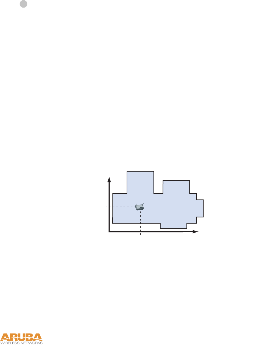
From the boot prompt, set the intended location for the Aruba 52:
If you performed the recommended site survey using the Aruba WLAN Switch’s built-in
planning tools, the location data for all access points and air monitors can be found on the
tool’s deployment screen (see the Aruba AirOS Software Guide).
If you plan to manually generate the location data, record the following information for each
access point and air monitor. It will be required when configuring the Aruba WLAN Switch.
apboot> setenv location <building number>.<floor number>.<device number>
Building Number A unique number (1-255) is required for each building in your campus.
Floor Number Within any building, a unique number (1-255) is required for each floor.
Device Number Within any floor, a unique number (1-65536) is required for each access
point or air monitor.
Device Description Note the intended function of the device (access point or dedicated air
monitor) and a brief description of its service location.
X, Y Coordinates For each access point and air monitor, measure its X and Y position (in
feet) relative to the bottom-left corner of the building plan as seen from
overhead. For example:
Use the same fixed point and orientation for all floors in a building.
1
0,0 126
98
X
418 ft.
Y
262 ft.
7/29/03 FINAL DRAFT—CONFIDENTIAL
16 Aruba 52 Part 0500007B
Installation Guide August 2003
Specify host information, if necessary.
The Aruba 52 uses the default host name aruba-master to find the host Aruba WLAN
Switch and download its software. This assumes that your DNS has been configured to
resolve aruba-master to the master Aruba WLAN Switch IP address.
zIf DNS is available, the AP will use servername environment variable to find the host and
download the AP software image and the configuration file (unless serverip and/or master
are set).
If DNS is not available, then the IP address of the server hosting the AP software image
and the address of the server hosting the configuration file must be specified. This is
accomplished using the environment variables serverip and master respectively.
NOTE—The software image and the configuration file are usually stored on the same
server.
zIf you are not using DNS, you must manually configure the Aruba 52 with the IP address
of the master Aruba WLAN Switch:
zIf you are using DNS but wish to specify a different host, use the following command:
CAUTION—The serverip and master environment variables take precedence
over the servername variable. Therefore, if you set serverip or naster the AP will
use those addresses to search for the software image and the configuration file
instead of looking for the server specified in servername.
apboot> setenv serverip
<switch IP address>
apboot> setenv master
<switch IP address>
apboot> setenv servername
<image host name>
2
Setup & Installation 17
Chapter 2
7/29/03 FINAL DRAFT—CONFIDENTIAL
Tabl e 2-2 summarizes the server environment variables discussed above.
Specify an IP address, if necessary.
If using DHCP, the Aruba 52 will obtain its IP address automatically and this step can be
skipped. Otherwise, the AP must be manually configured with a static IP address using the fol-
lowing commands:
Save the configuration and reboot the Aruba 52.
Once the Aruba 52 boots, disconnect it and mount it in its intended service location (see
instructions on page 18).
TABLE 2-2 Server Enviornment Variable
Variable Name Default Value Use Comments
servername aruba-master DNS name of the
master M-switch.
Also serves as the
TFTP servername if
serverip is not set.
serverip n/a IP address of the
TFTP server.
Overides servername
for TFTP image
download. Use only
if DNS is unavail-
able or must be
bypassed.
master n/a IP address of the
master M-switch.
Overides servername.
Use if DNS is
unavailable or must
be bypassed.
apboot> setenv ipaddr
<static IP address for the AP>
apboot> setenv netmask
<static IP address mask>
apboot> setenv gatewayip
<default gateway IP address>
apboot> save
apboot> boot
3
4
7/29/03 FINAL DRAFT—CONFIDENTIAL
18 Aruba 52 Part 0500007B
Installation Guide August 2003
Mount the Aruba 52
When initial setup is complete, mount the Aruba 52 in its intended service location.
Select a location as close as possible to the center of the intended coverage area. If necessary,
use the Aruba WLAN Switch’s built-in site survey software to determine the optimum loca-
tions for your access points and air monitors (see your Aruba AirOS Software Guide).
The service location should be free from obstructions or obvious sources of interference. Nor-
mally, the higher you place an access point or air monitor, the better its performance.
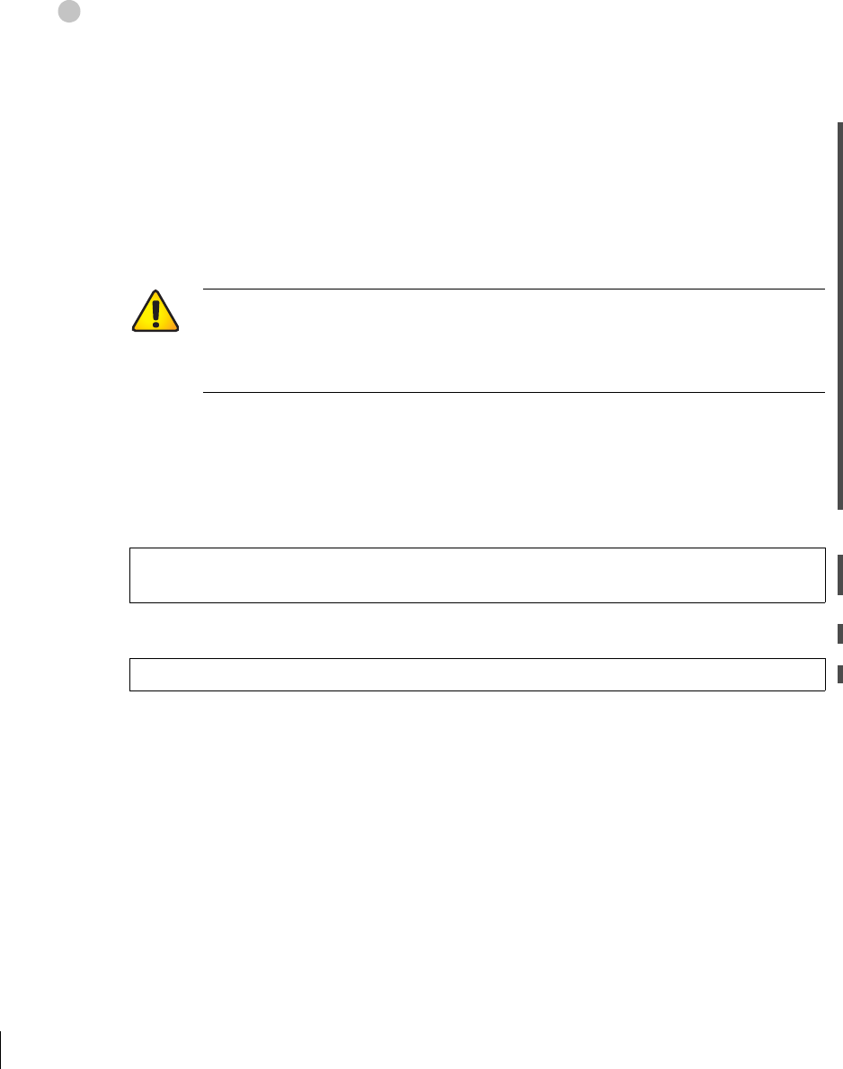
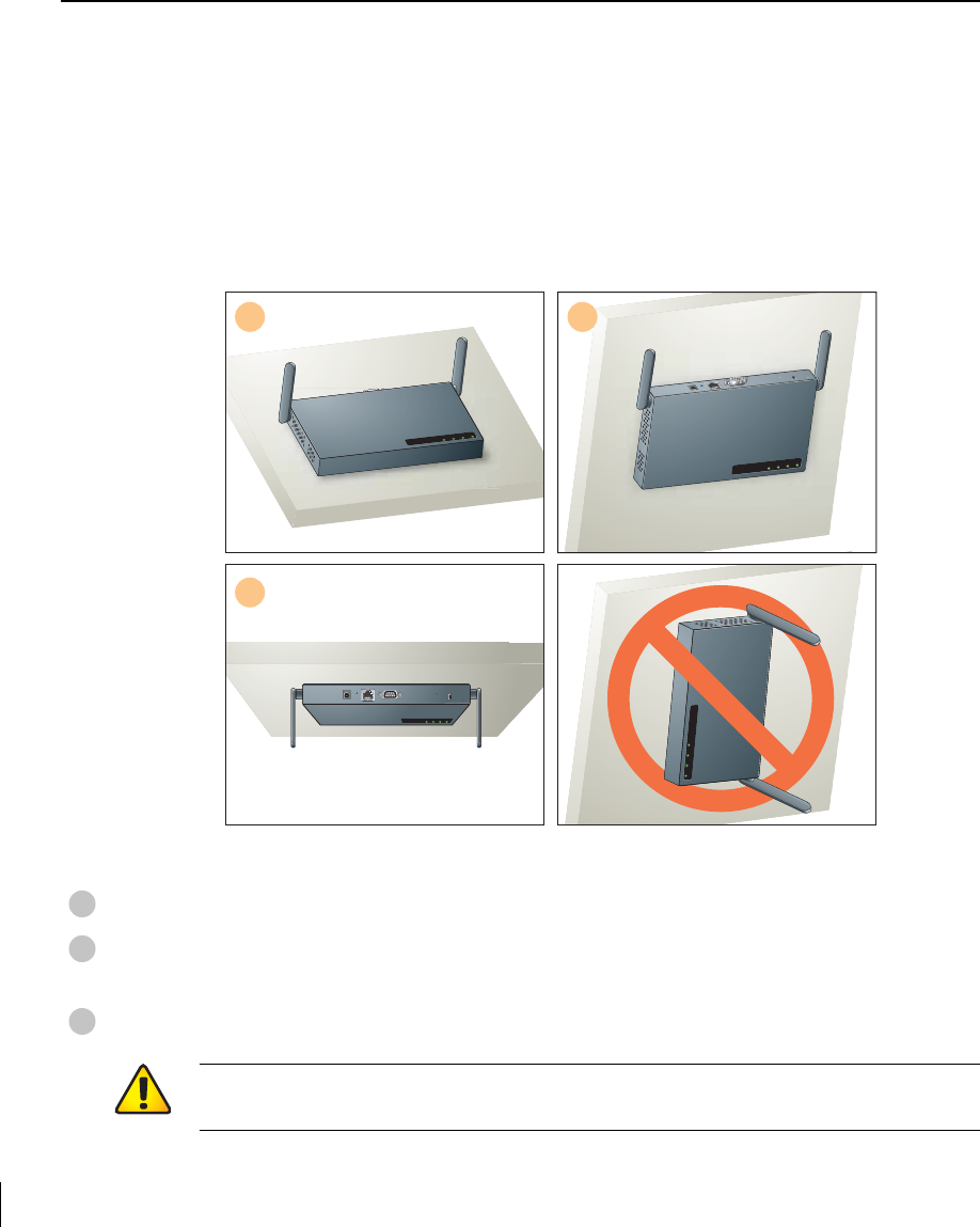
The Aruba 52 can be mounted in the following ways:
FIGURE 2-2 Aruba 52 Mounting Options
Flat on a table or shelf (with the LEDs on top)
Upright on a wall (with the port connectors on top) using the built-in mounting slots
or the optional mounting kit
Suspended from above (with the LEDs on bottom) using the optional mounting kit
12
3
READY LAN .A .B
READYLAN.A.B
READY LAN .A .B
1
2
3
CAUTION—For safety purposes, do not mount the Aruba 52 sideways (with the air
vents on top and bottom).
Setup & Installation 19
Chapter 2
7/29/03 FINAL DRAFT—CONFIDENTIAL
Free-Standing Placement
To place the Aruba 52 on a flat table or shelf, first attach the included non-skid foot-pads to
the bottom of the chassis.
Using the Built-In Mounting Slots
The keyhole-shaped slots on the bottom of the Aruba 52 can be used to attach the device to a
wall or shelf.
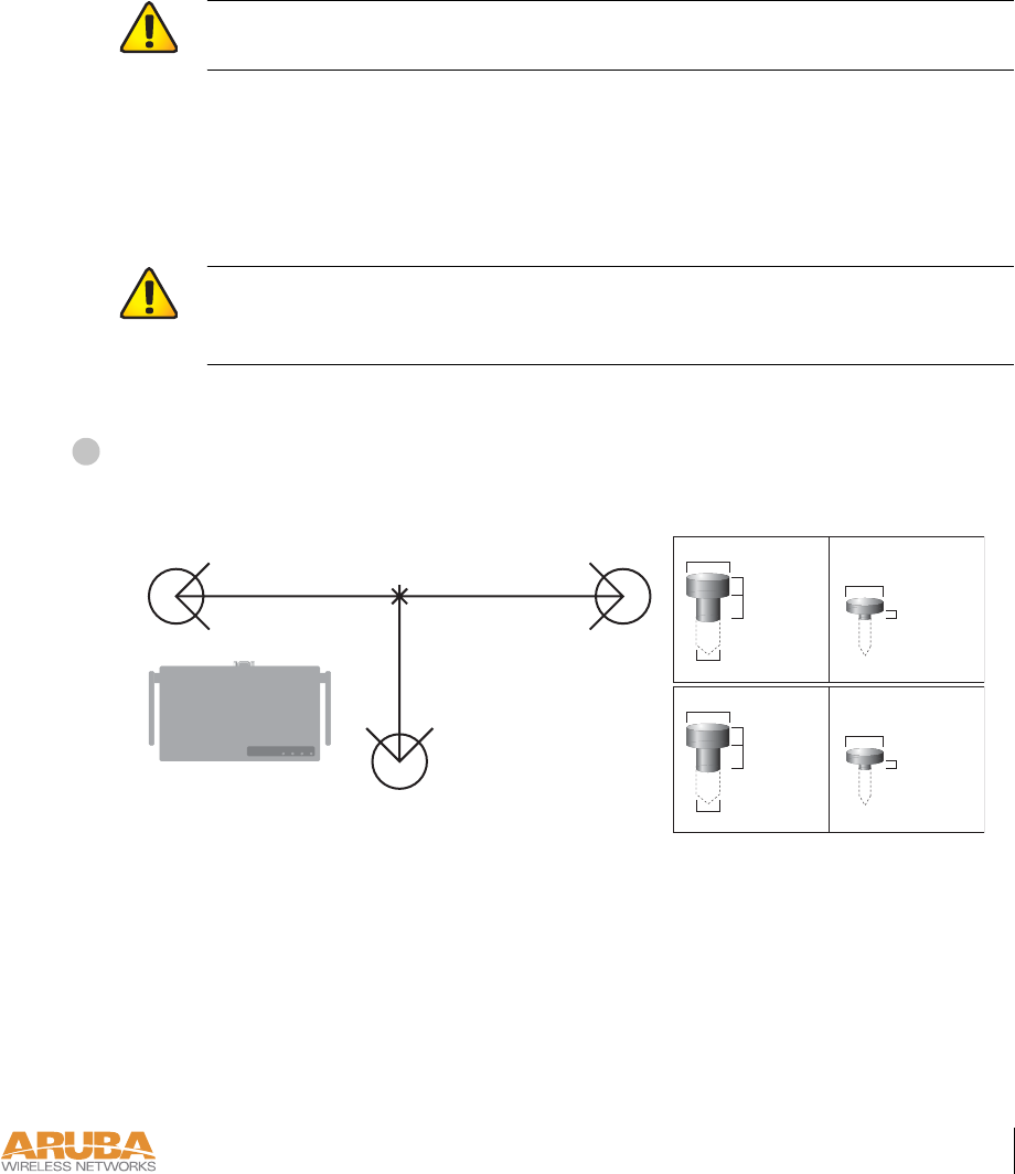
To hang the Aruba 52, perform the following steps.
Install three screws in the wall or shelf as shown in Figure 2-3:
FIGURE 2-3 Mounting Screw Specifications
If attaching the device to drywall, we recommend using appropriate wall anchors (not
included) as shown in Figure 2-4.
CAUTION—Do not place the Aruba 52 in any place where it could fall on people or
equipment. For more secure installation, use the optional mounting kit.
CAUTION—Do not use the mounting slots to hang the Aruba 52 from the ceiling
or in any place where it could fall on people or equipment. For more secure installa-
tion, use the optional mounting kit.
1
READY LAN .A .B
Orientation
7.27 cm
(2.86")
7.27 cm
(2.86")
5.5 cm
(2.17")
0.12"
0.27"
0.23"
0.05"
clearance
from surface
3.0 mm
5.8 mm
0.08"
0.15"
clearance
from surface
2.0 mm
3.8 mm
clearance
from surface
1.3 mm
clearnace
from surface
7.0 mm
Maximum Minimum
Screw/Nail DimensionsScrew/Nail Positions
(fastened to wall or shelf)
Measuring
Point
7/29/03 FINAL DRAFT—CONFIDENTIAL
20 Aruba 52 Part 0500007B
Installation Guide August 2003
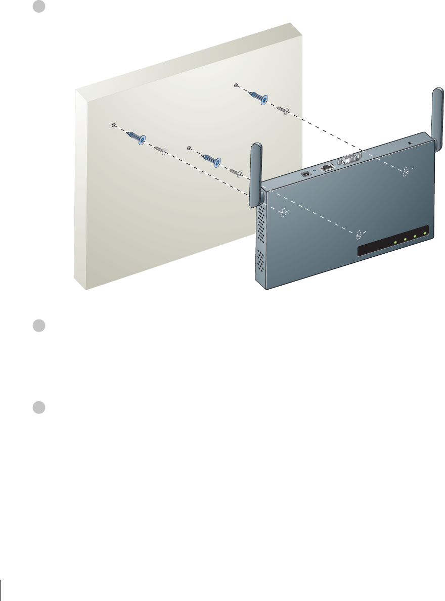
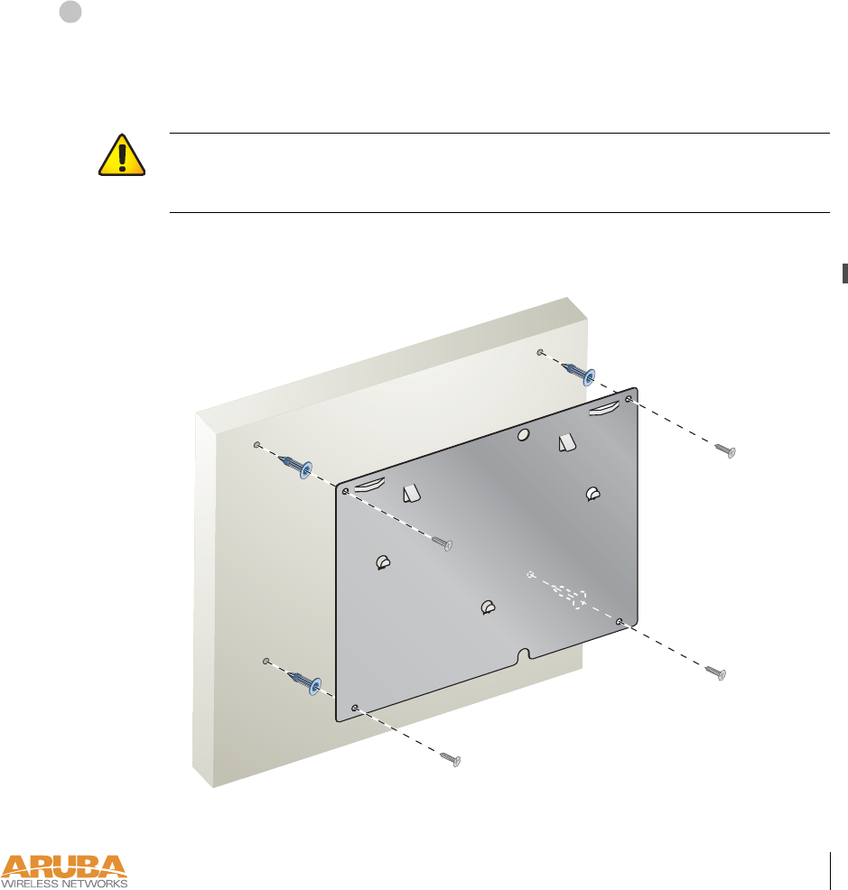
Align the Aruba 52 mounting slots to capture the surface screws.
FIGURE 2-4 Hanging the Aruba 52 on Screws
Secure the Aruba 52, if desired.
To prevent the unauthorized removal of the Aruba 52 from its installed location, use a Kens-
ington MicroSaver Security Cable (not included). Wrap the security cable around an immov-
able object, insert the cable’s lock into the Kensington Security Slot on the back of the
Aruba 52, and turn the key.
Orient the antennas.
For best performance, swivel the antennas so that they are oriented vertically (see Figure 2-2 on
page 18). Once mounting is complete, connect the required cables (see instructions on page 25).
2
READY LAN .A .B
3
4
Setup & Installation 21
Chapter 2
7/29/03 FINAL DRAFT—CONFIDENTIAL
Using the Optional Mounting Kit
Use the optional mounting kit to attach the Aruba 52 to a wall, shelf, or ceiling.
NOTE—Do not attach the rubber foot-pads to the Aruba 52 when using the mounting kit.
Wall, Shelf, or Solid Ceiling Mount
Attach the mounting cradle to the mounting surface.
Place the flat side of the cradle against the mounting surface. If attaching the cradle to a wall,
orient it so that the cable tie anchors are positioned at the top. If attaching the cradle to a table,
shelf, or solid ceiling, orient the cable tie anchors toward the cable route.
Use the four #6 screws (or equivalent) to secure the cradle to the solid surface. If attaching the
cradle to drywall, we recommend using appropriate wall anchors (not included) as show below:
FIGURE 2-5 Attaching the Mounting Cradle
1
S
CAUTION—Do not use screws to attach the mounting cradle to a suspended ceil-
ing or other structurally weak surface. For suspended ceilings, use the T-rail clips as
described on page 23 instead.
7/29/03 FINAL DRAFT—CONFIDENTIAL
22 Aruba 52 Part 0500007B
Installation Guide August 2003
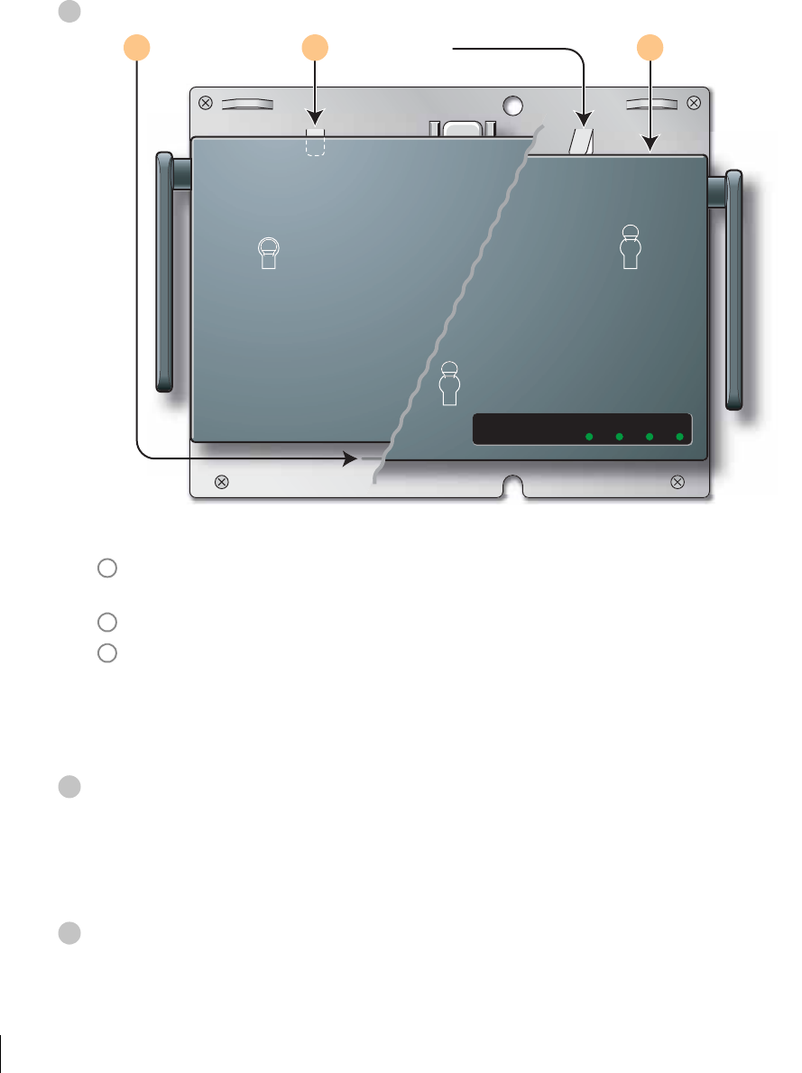
Place the Aruba 52 into the mounting cradle as shown in Figure 2-6.
FIGURE 2-6 Placing the Aruba 52 into the Cradle
Align the front edge of the chassis with the etched line on the mounting cradle. This will
fit the Aruba 52 mounting slots over the matching cradle posts.
Press and hold the Aruba 52 chassis against the retaining clips on the cradle.
Slide the Aruba 52 into place. When properly positioned, the retaining clips will spring
up to hold the chassis firmly in place.
NOTE—To remove the Aruba 52 from the cradle, press down on both retaining clips and
slide the chassis free of the mounting posts.
Secure the Aruba 52, if desired.
To prevent the unauthorized removal of the Aruba 52 from its installed location, use a Kens-
ington MicroSaver Security Cable (not included). Wrap the security cable around an immov-
able object, insert the cable’s lock into the Kensington Security Slot on the back of the
Aruba 52, and turn the key.
Orient the antennas.
For best performance, swivel the antennas so that they are oriented vertically (see Figure 2-2 on
page 18). Once mounting is complete, connect the required cables (see instructions on page 25).
2
READY LAN .A .B
Press chassis
against clips
Align with
etched line
Slide into
position
A B C
A
B
C
3
4
Setup & Installation 23
Chapter 2
7/29/03 FINAL DRAFT—CONFIDENTIAL
Suspended Ceiling Mount
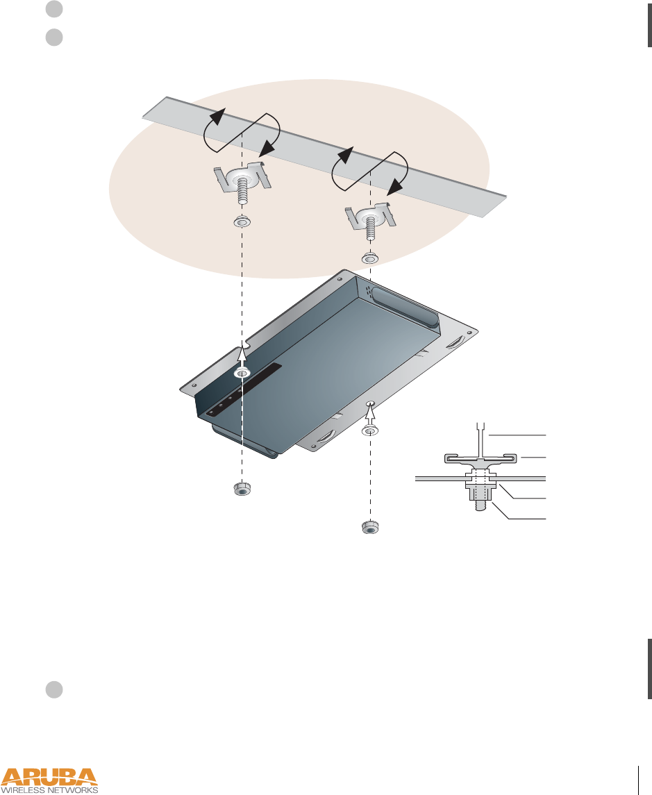
Place the Aruba 52 into the mounting cradle as shown in Figure 2-6 on page 22.
Use the T-rail clips, nylon washers, and nuts included in the optional mounting kit
to attach the Aruba 52 to the underside of a suspended ceiling.
FIGURE 2-7 Mounting on a Suspended Ceiling
The T-rail clips twist onto the rails used with standard suspended-ceiling systems. Place the
T-rail clips approximately 15 cm (6 inches) apart at the location where the Aruba 52 will be
installed. Use the mounting cradle to gauge the appropriate distance between the clips.
Use the nylon washers to insolate the cradle from electrical contact with the T-rail. Make sure to
insert the raised ridge of the lower washers fully into the cradle mounting holes as shown above.
Orient the antennas.
For best performance, swivel the antennas so that they are oriented vertically (see Figure 2-2 on
page 18). Once mounting is complete, connect the required cables (see instructions on page 25).
1
2
READYLAN.A .B
Cradle
T-Rail
Clip
Washers
Nut
Side View
3

7/29/03 FINAL DRAFT—CONFIDENTIAL
24 Aruba 52 Part 0500007B
Installation Guide August 2003
Connect Required Cables
The cables required for operating the Aruba 52 depend on your intended network topology
(see Figure 2-1 on page 8) and on the physical location.
Direct SPOE to the Aruba WLAN Switch
Use this procedure when connecting the Aruba 52 directly to an SPOE-compatible network
port on the Aruba WLAN Switch (see “Power Over Ethernet” on page 2). SPOE provides
10/100 Mbps Ethernet, serial connection, and power over one cable.
NOTE—If connecting the Aruba 52 through the LAN or to a non-SPOE network port on
the Aruba WLAN Switch, see the instructions on page 26.
Connect the SPOE adapter to the Aruba 52.
Connect the adapter’s 9-pin serial connector to the Console port on the back of the
Aruba 52.
Connect the adapter’s male RJ-45 plug to the FE port on the back of the Aruba 52.
Connect the Aruba 52 to the Aruba WLAN Switch.
The connection between the Aruba 52 and the Aruba WLAN Switch requires an 8-conduc-
tor, Category 5 UTP, straight-through FE cable with RJ-45 connectors (see Appendix A for
port specifications).
Any FE cable installed in an air-handling space, as described in NEC (2002) Article 300.22(C),
should be suitable under NEC Article 800.50 and marked accordingly for use in plenums and
air-handling spaces with regard to smoke propagation, such as CL2-P, CL3-P, MPP or CMP.
Install cables in accordance with all applicable local regulations and practices.
Connect one end of the FE cable directly to the RJ-45 socket on the SPOE adapter that
was attached to the Aruba 52 in the previous step.
Connect the other end of the FE cable directly to an available SPOE network port on the
Aruba WLAN Switch.
NOTE—The Aruba 52 must be connected to the Aruba WLAN Switch without any inter-
vening hubs, routers, or other networking equipment.
1
A
B
2
A
B

Setup & Installation 25
Chapter 2
7/29/03 FINAL DRAFT—CONFIDENTIAL
LAN or POE Connection
Use this procedure when connecting the Aruba 52 through the LAN or to a non-SPOE net-
work port on theAruba WLAN Switch.
NOTE—If connecting the Aruba 52 directly to a SPOE network port on the Aruba WLAN
Switch, see the instructions on page 25.
Connect the Aruba 52 to the network.
Connect one end of an FE cable to a network hub, router, or switch that has a routable
path to the Aruba WLAN Switch.
zIf the connecting device supports POE (see “Power Over Ethernet” on page 2), use an
8- or 4-conductor, Category 5 UTP, straight-through FE cable.
zIf the connecting device does not support POE, use a 4- or 8-conductor, Category 5
UTP, straight-through or crossover FE cable.
Any FE cable installed in an air-handling space, as described in NEC (2002) Article
300.22(C), should be suitable under NEC Article 800.50 and marked for use in plenums
and air-handling spaces with regard to smoke propagation, such as CL2-P, CL3-P, MPP
or CMP. Install cables in accordance with all applicable local regulations and practices.
For port and cable details, see Appendix A.
Connect the other end of the FE cable to the FE port on the back of the Aruba 52.
CAUTION—To prevent personal injury or damage to equipment, be sure to com-
ply with electrical grounding standards during all phases of installation and operation
of the AP. Do not allow theAruba 52 to contact metal which is connected a different
electrical ground than the Aruba WLAN Switch. Also, never connect the AP or
WLAN switch to external storm grounding sources.
1
A
B
7/29/03 FINAL DRAFT—CONFIDENTIAL
26 Aruba 52 Part 0500007B
Installation Guide August 2003
Connect power.
The Aruba 52 can receive electrical power using the following options:
zPOE–If connecting the Aruba 52 to a device that supplies IEEE 802.3af compliant POE
(see “Power Over Ethernet” on page 2), no additional power connection is necessary.
zPower Outlet
NOTE—When the Aruba 52 is installed in an air-handling space, as described in NEC
(2002) Article 300.22(C), POE must be used instead of a power outlet.
If local regulations and practices permit, connect the included AC power adapter cable to
the DC power socket on the rear panel of the Aruba 52 and plug it into an appropriate
power outlet.
Reviewers:
Is shared secret config implemented?
CAUTION—Be sure to comply with electrical grounding standards during all
phases of installation and operation of the AP. Do not allow the Aruba 52 or power
adapter (if used) to be connected to or make contact with metal or power outlets on a
different electrical ground than the device to which it is connected. Also, never con-
nect the AP to external storm grounding sources.
CAUTION—Use only the AC power adapter supplied with this device. Other-
wise, the product may be damaged.
2

Setup & Installation 27
Chapter 2
7/29/03 FINAL DRAFT—CONFIDENTIAL

7/29/03 FINAL DRAFT—CONFIDENTIAL
28 Aruba 52 Part 0500007B
Installation Guide August 2003
Port Specifications 29
Appendix A
7/29/03 FINAL DRAFT—CONFIDENTIAL7/29/03 FINAL DRAFT—CONFIDENTIAL
APPENDIX A
Port Specifications
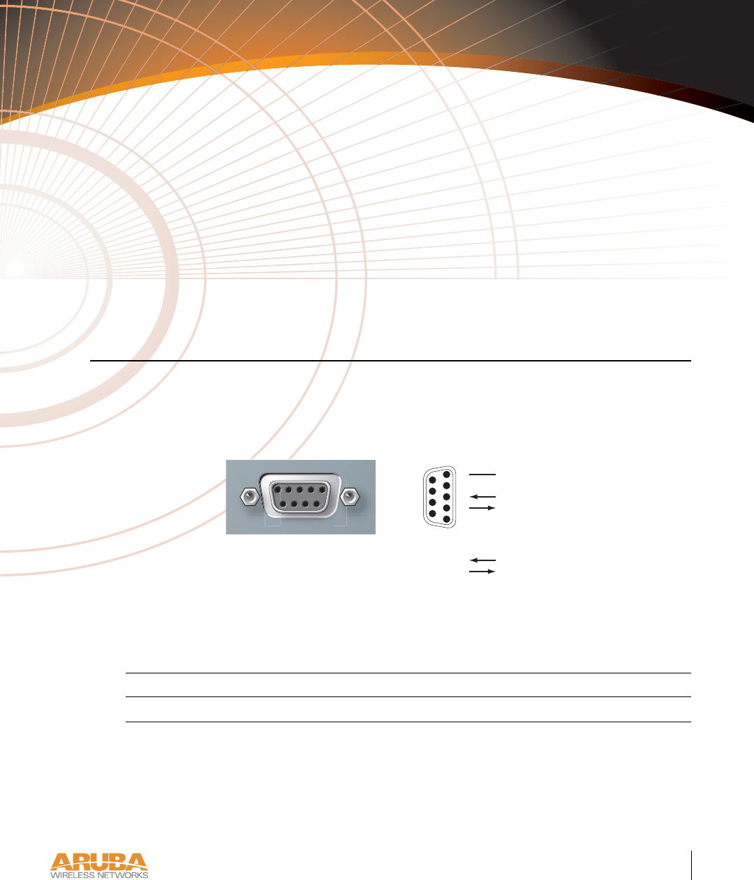
Console Port
The console port is located on the back of the Aruba 52 and has a DB-9 female connector. Port
pin-outs are shown in Figure A-1:
Figure A-1 Aruba 52 Console Port
Communication settings for the console port are specified in Table A- 1:
Tab l e A -1 Console Terminal Settings
Baud Rate Data Bits Parity Stop Bits Flow Control
9600 8 None 1 None
Direction
RxD
TxD
SG
5
4
3
2
1
9
8
7
6
Input
Output
Aruba 52
Console
DB-9 Female
DCE Pin-Out

7/29/03 FINAL DRAFT—CONFIDENTIAL
30 Aruba 52 Part 0500007B
Installation Guide August 2003
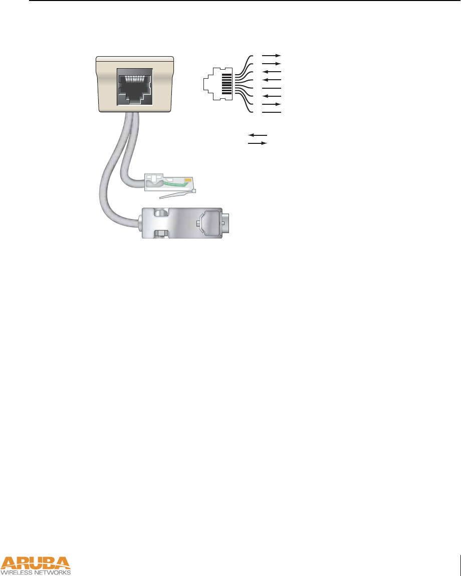
FE Port
The 10/100 Mbps Ethernet (FE) port is located on the back of the Aruba 52 and has an RJ-45
female connector. Port pin-outs are shown in Figure A-2:
Figure A-2 Aruba 52 FE Port
The port accepts a 4- or 8-conductor Category 5 UTP FE cable with an RJ-45 male connector.
The FE port detects MDI/MDX and automatically adjusts for straight-through or crossover
cables. However, if Power Over Ethernet (POE) is used, a straight-through cable is required.
The maximum length for FE cables is 100 meters (325 feet).
When the Aruba 52 is installed in an air-handling space, as described in NEC (2002) Article
300.22(C), POE is required. Also, any FE cable installed in such spaces should be suitable
under NEC Article 800.50 and marked accordingly for use in plenums and air-handling spaces
with regard to smoke propagation, such as CL2-P, CL3-P, MPP or CMP.
Install cables in accordance with all applicable local regulations and practices.
Aruba 50
10/100 Mbps Ethernet
1
2
3
4
5
6
7
8
Rx+ (POE negative*)
Rx– (POE negative*)
Tx+ (POE positive*)
Tx– (POE positive*)
RJ-45 Female
Pin-Out
*POE optional
Direction
Input
Output
Port Specifications 31
Appendix A
7/29/03 FINAL DRAFT—CONFIDENTIAL
SPOE Adapter
The Serial & Power Over Ethernet (SPOE) adapter pin-outs are shown in Figure A-3:
Figure A-3 Aruba SPOE Adapter
The adapter requires an 8-conductor Category 5 UTP, straight-through FE cable with RJ-45
male connectors. The cable must connect the SPOE adapter to an FE+SPOE port on the
Aruba WLAN Switch, with no intervening hubs, routers, or other network equipment.
The maximum length for FE cables is 100 meters (325 feet).
The Aruba 52 and SPOE adapter are plenum rated. When is installed in an air-handling
space, as described in NEC (2002) Article 300.22(C), the connecting FE cable should be suit-
able under NEC Article 800.50 and marked accordingly for use in plenums and air-handling
spaces with regard to smoke propagation, such as CL2-P, CL3-P, MPP or CMP.
Install cables in accordance with all applicable local regulations and practices.
SPOE Adapter
Serial TxD
Serial TGND
Serial RxD
Serial RGND
RJ-45 Male to Aruba 50
10/100 Mbps Ethernet Port
RJ-45 Female Pin-Out
DB-9 Male to Aruba 50
Console Port
1
2
3
4
5
6
7
8
ETH Rx+ (POE negative)
ETH Rx– (POE negative)
ETH Tx+ (POE positive)
ETH Tx– (POE positive)
Direction
Input
Output

7/29/03 FINAL DRAFT—CONFIDENTIAL
32 Aruba 52 Part 0500007B
Installation Guide August 2003

Product Specifications 33
Appendix B
7/29/03 FINAL DRAFT—CONFIDENTIAL
APPENDIX B
Product Specifications
The following specifications apply to the Aruba 52 Wireless Access Point (model WAP-50).
Physical
Environment
TABLE B-1 Physical Specifications
Item Measurement
Size 20.5 x 13.6 x 4 cm
(8.07 x 5.35 x 1.58 in)
Weight 280 gram (9.9 oz.)
TABLE B-2 Environmental Specifications
Item Measurement
Temperature Operating: 0 to 50 ºC (32 to 122 ºF)
Storage: 0 to 70 ºC (32 to 158 ºF)
Humidity 5% to 95% (non-condensing)
7/29/03 FINAL DRAFT—CONFIDENTIAL
34 Aruba 52 Part 0500007B
Installation Guide August 2003
Operation
General
TABLE B-3 Operational Specifications
Item Measurement
Maximum Channels 802.11a—US & Canada: 13, Japan: 5
802.11b/g—US & Canada: 1-11, Europe: 1-13, France: 10-13,
Japan: 1-14, Spain: 10-11
Maximum Clients 64
Data Rate 802.11a—6, 9, 12, 18, 24, 36, 48, 54 Mbps per channel
802.11b—1, 2, 5.5, 11 Mbps per channel
802.11g—6, 9, 12, 18, 24, 36, 48, 54 Mbps per channel
Operating Frequency 802.11a—
5.15 ~ 5.25 GHz (lower band) US/Canada, Japan
5.25 ~ 5.35 GHz (middle band) US/Canada
5.725 ~ 5.825 GHz (upper band) US/Canada
802.11b/g—
2.412 ~ 2.452 GHz US/Canada, Japan
2.457 ~ 2.462 GHz US/Canada, Europe, France, Japan, Spain
2.467 ~ 2.472 GHz Europe, France, Japan
2.484 GHz Japan
Output Power 100 mW maximum (or lower as configured on the Aruba WLAN
Switch to comply with local regulatory requirements)
Power Adapter Input—
100-240 AC, 50-60 Hz
Access Point Input—
3.3 VDC, 3 A (AC adapter), or
48 VDC, 150 mA (POE)
LED Indicators Ready (Power), LAN (Ethernet Link/Activity), .A and .B/.G
(Access Point/Air Monitor Mode)
Standards IEEE 802.3 10Base-T, IEEE 802.3u 100Base-TX,
IEEE 802.11a/b/g, IEEE 802.3af
Product Specifications 35
Appendix B
7/29/03 FINAL DRAFT—CONFIDENTIAL
Certifications
TABLE B-4 Certifications
Item Measurement
Electromagnetic
Compatibility
FCC Part 15 Class B, FCC Part 15 Class C 15.207/15.247,
FCC Part 15 Class E 15.407
ICES-003,
RSS 210 (CAN)
IEC 61000-4-2/3/4/6/11
EN 55022, EN55024 (89/336/EEC),
ETS 300 328 (89/336/EEC), ETS 301 489 (89/336/EEC),
ETS 301 893
AS/NZS 3548,
RFS 29 (NZ)
Safety CSA/NTRL (CSA 22.2 No. 950 & UL 1950)
EN60950 (TÜV/GS), IEC60950 (CB), UL 2043

7/29/03 FINAL DRAFT—CONFIDENTIAL
36 Aruba 52 Part 0500007B
Installation Guide August 2003