Hewlett Packard Enterprise BJNGAFB0002 HP 425 Wireless 802.11n (AM) AP User Manual
Hewlett-Packard Company HP 425 Wireless 802.11n (AM) AP
UserManual.wiki
>
Hewlett Packard Enterprise
>
BJNGAFB0002 User Manual
>
user manual
Contents
1.
user manual (statement) rev
2.
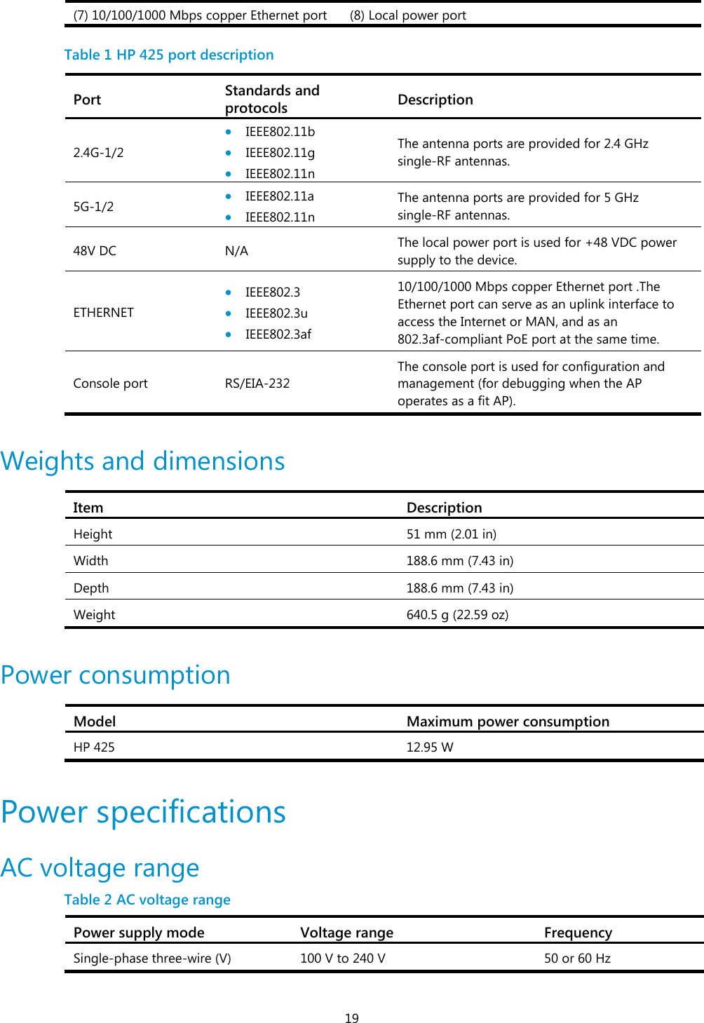
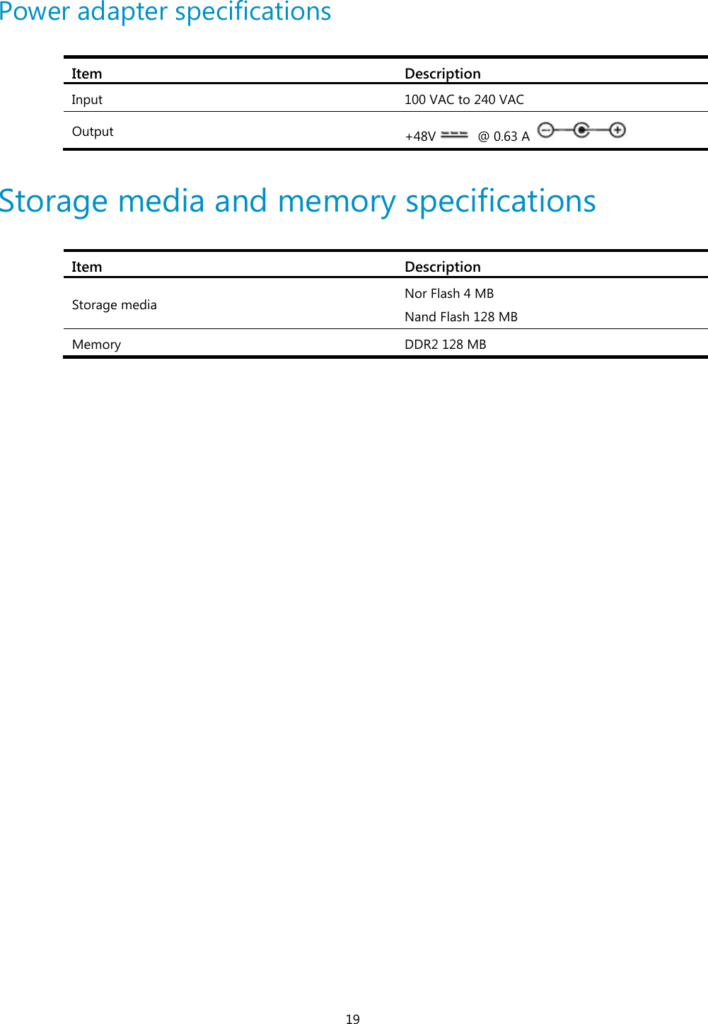
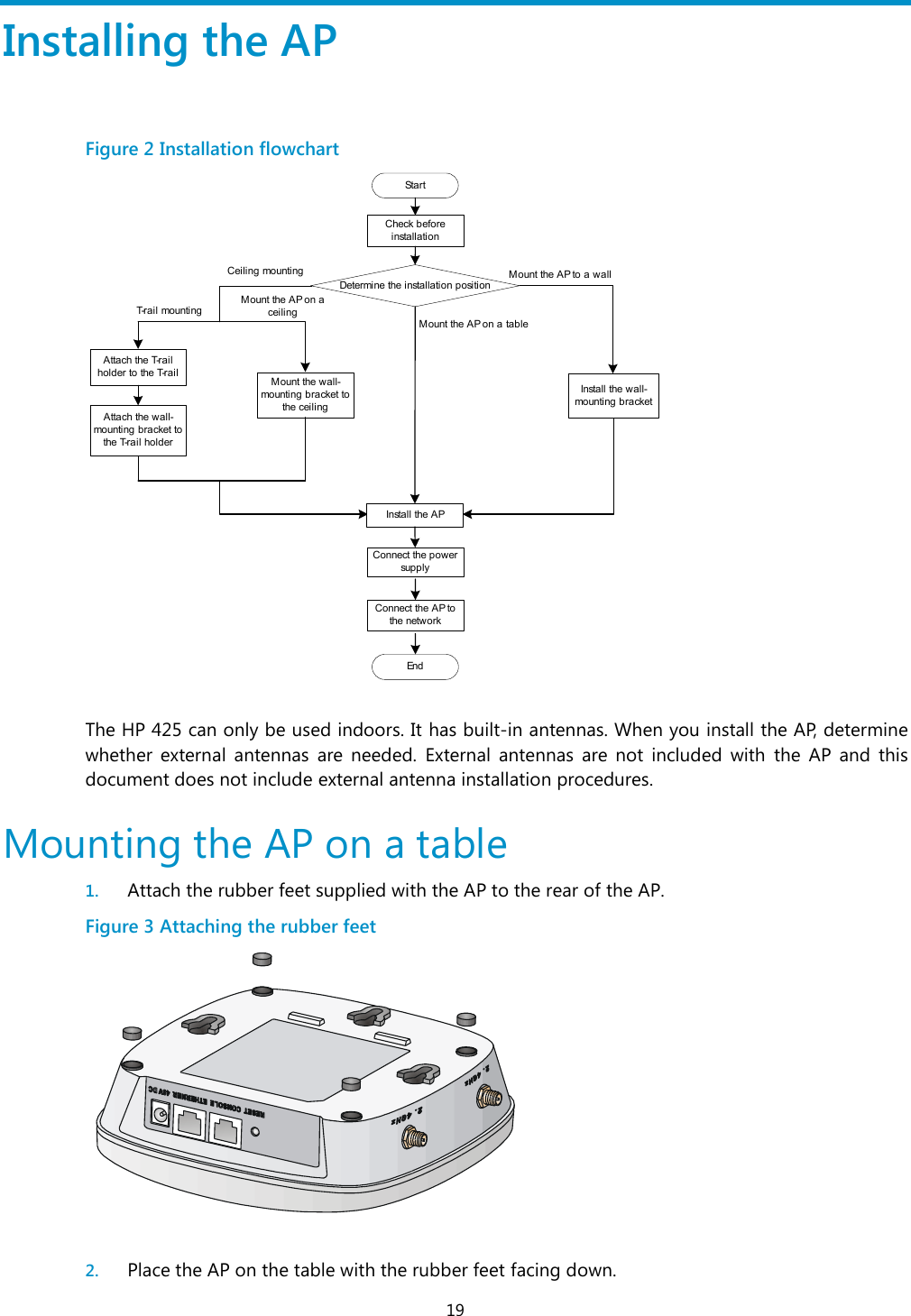
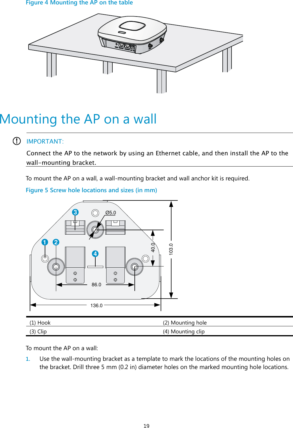
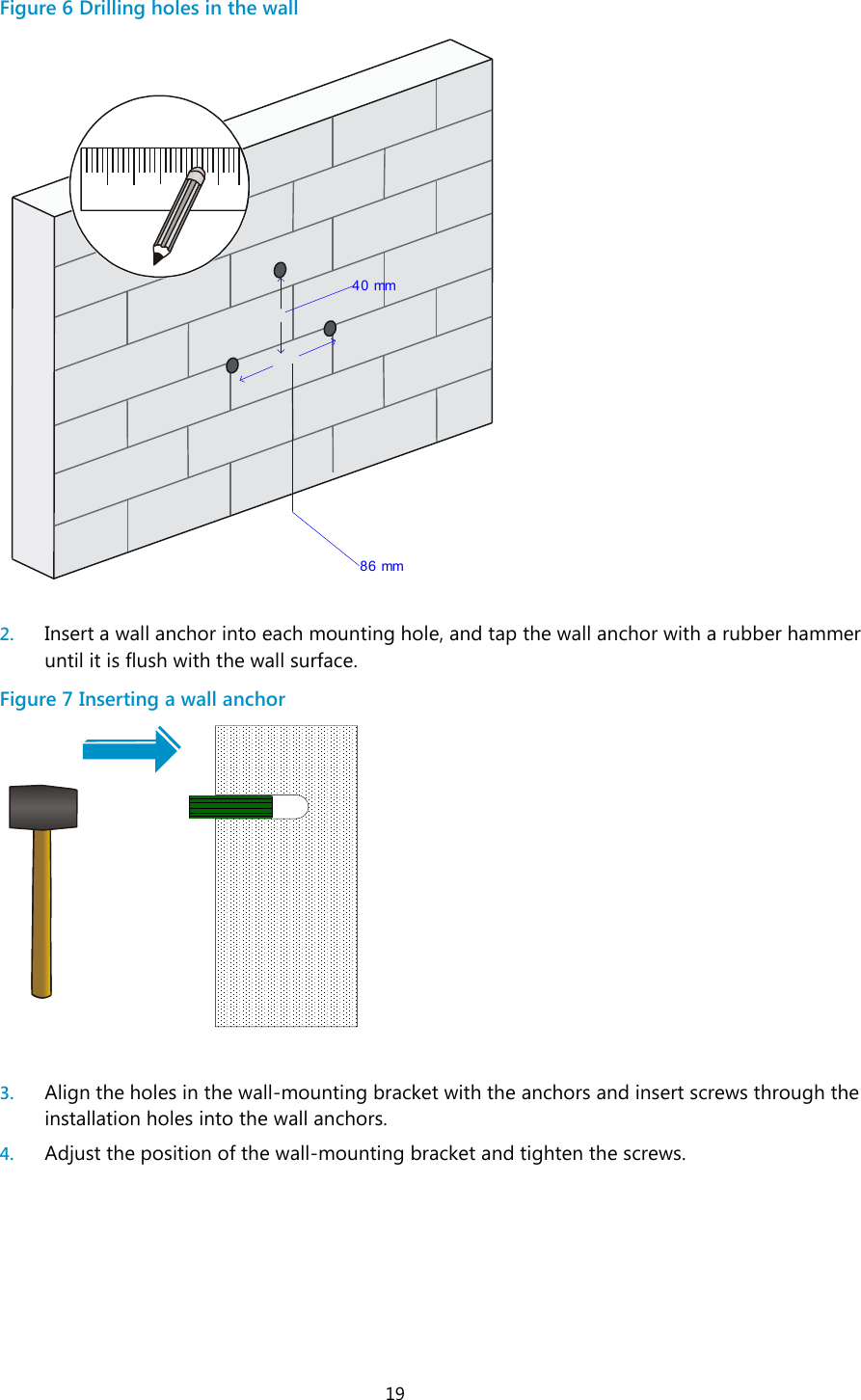
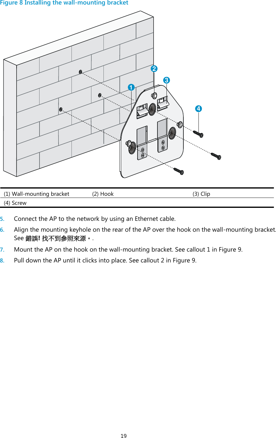
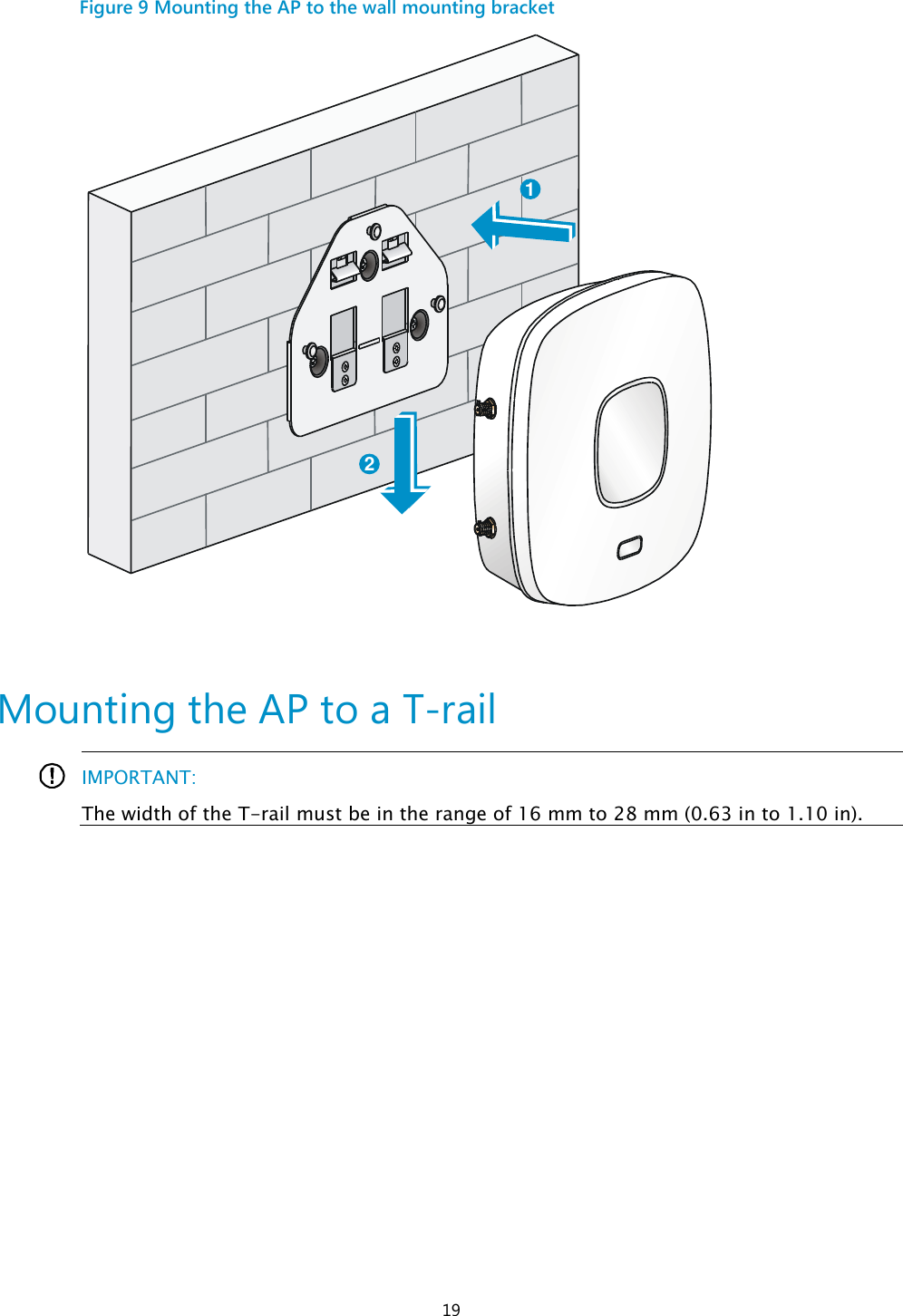
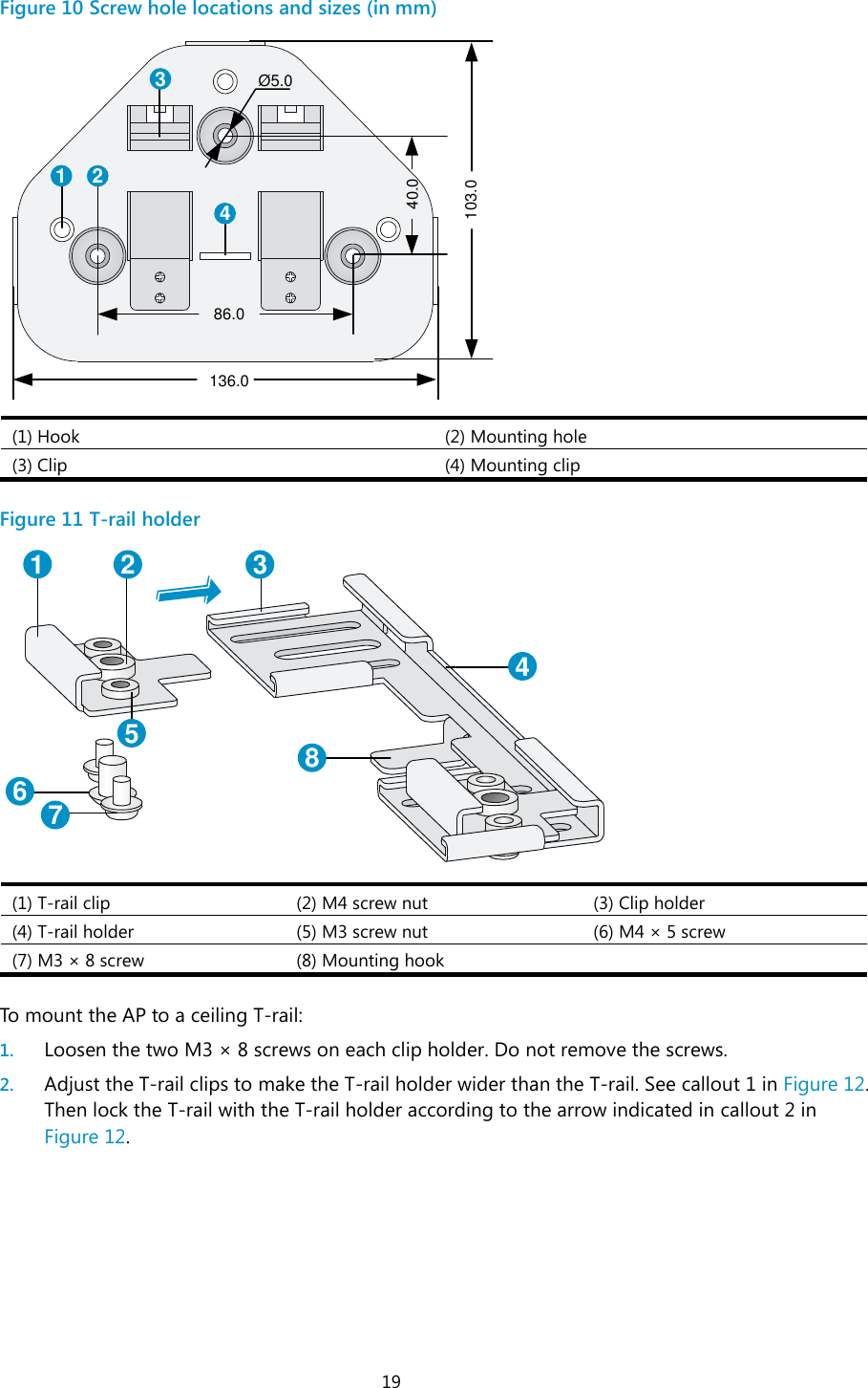
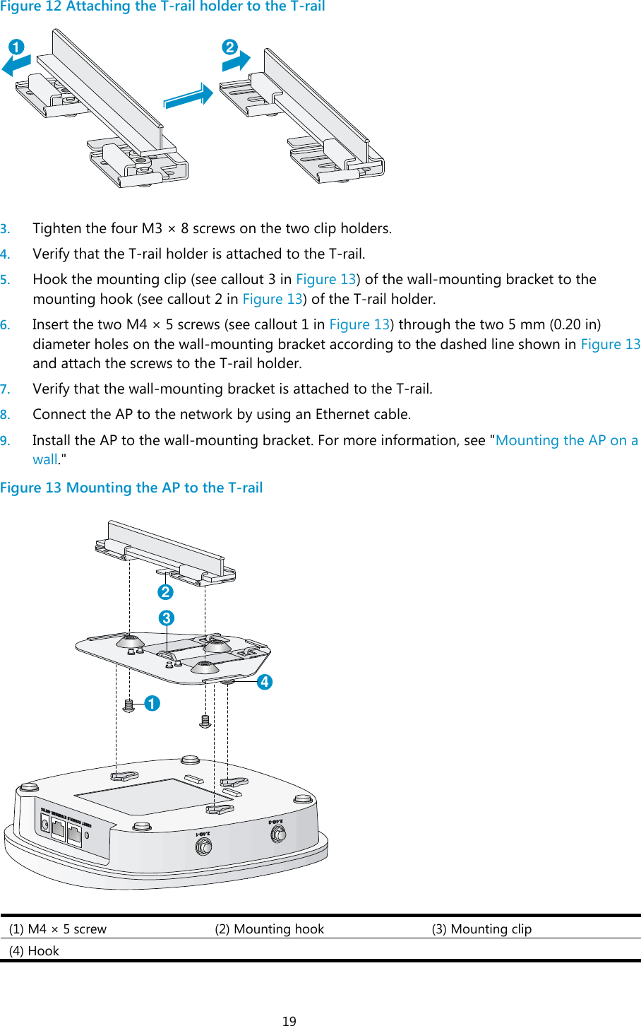
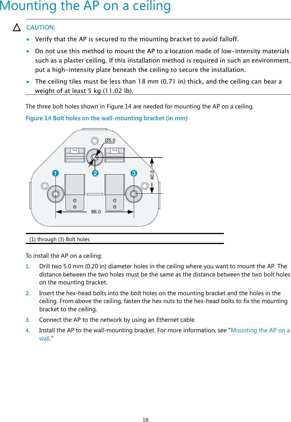
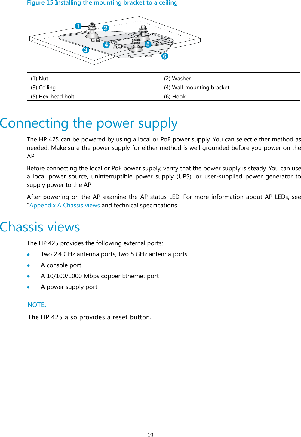
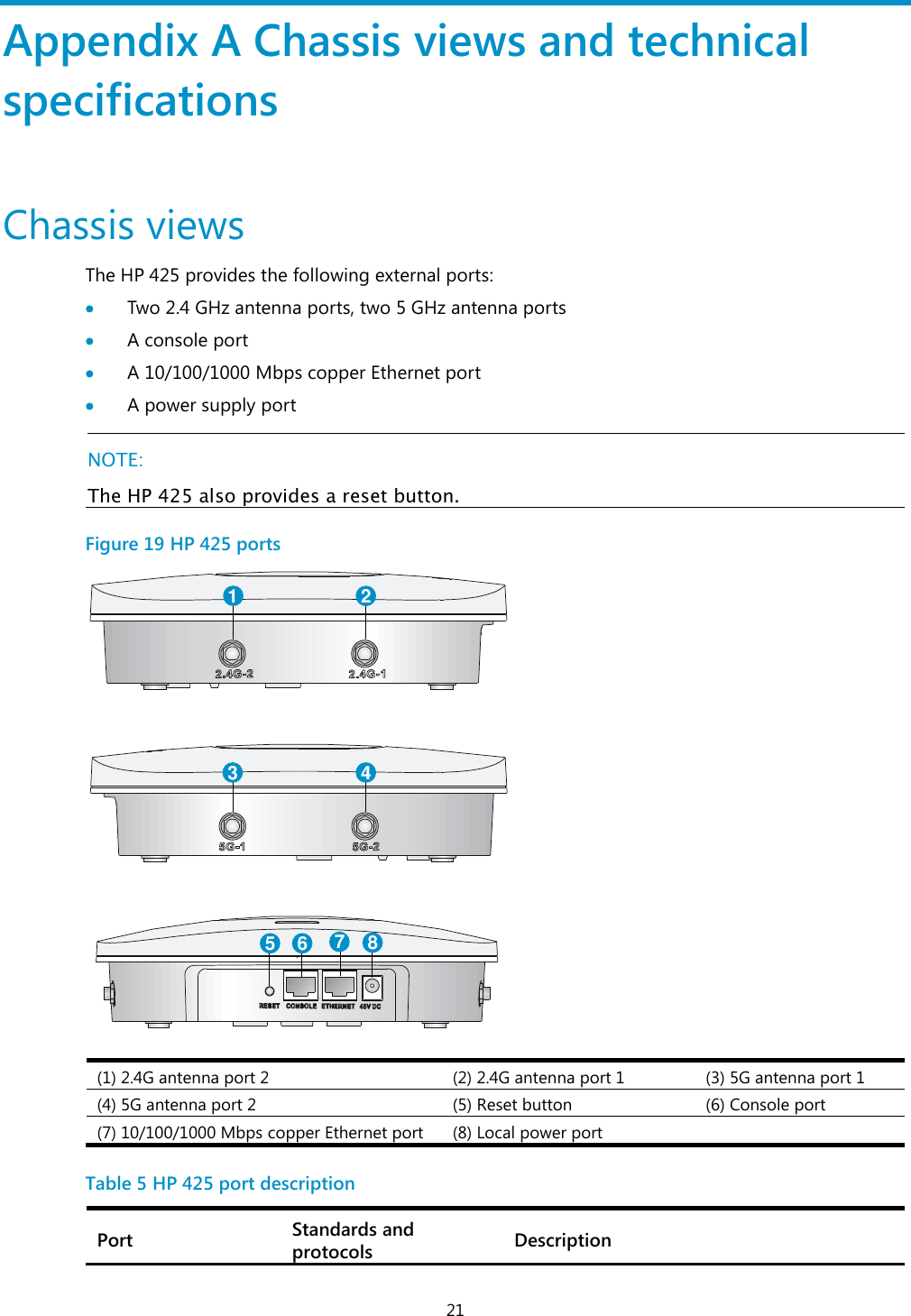
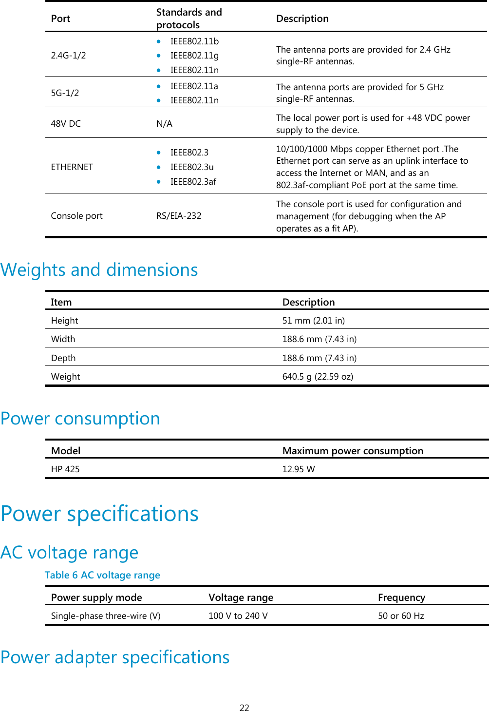
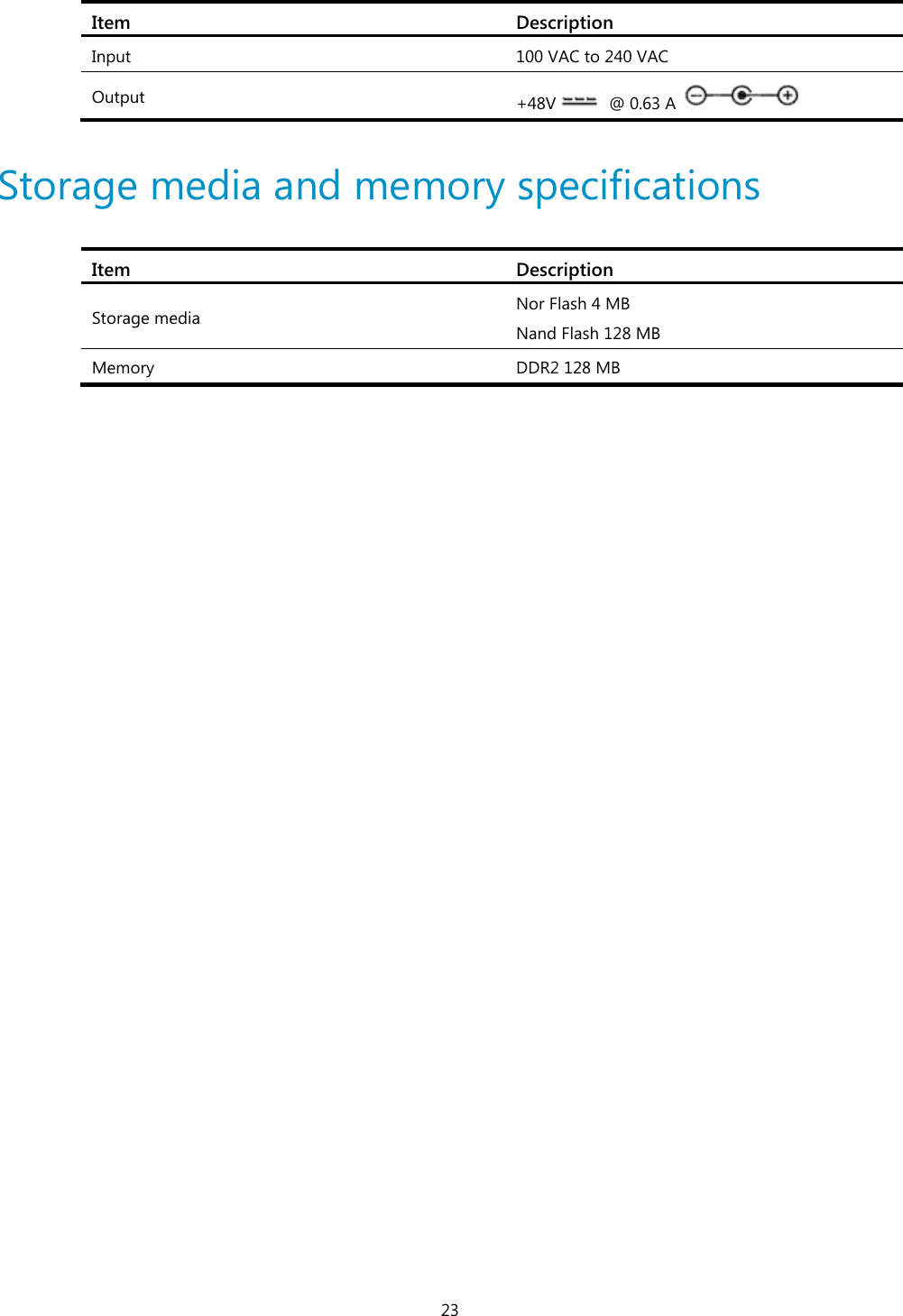
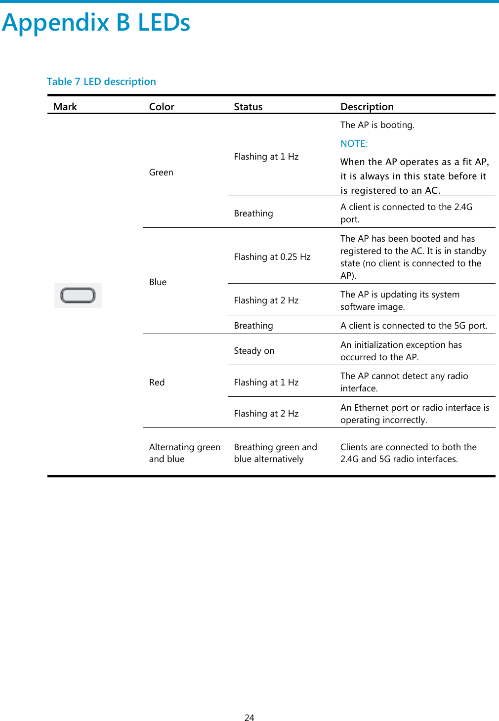
user manual
user manual
Navigation menu
Upload a User Manual
Namespaces
Wiki Guide
HTML
PDF
Info
Views
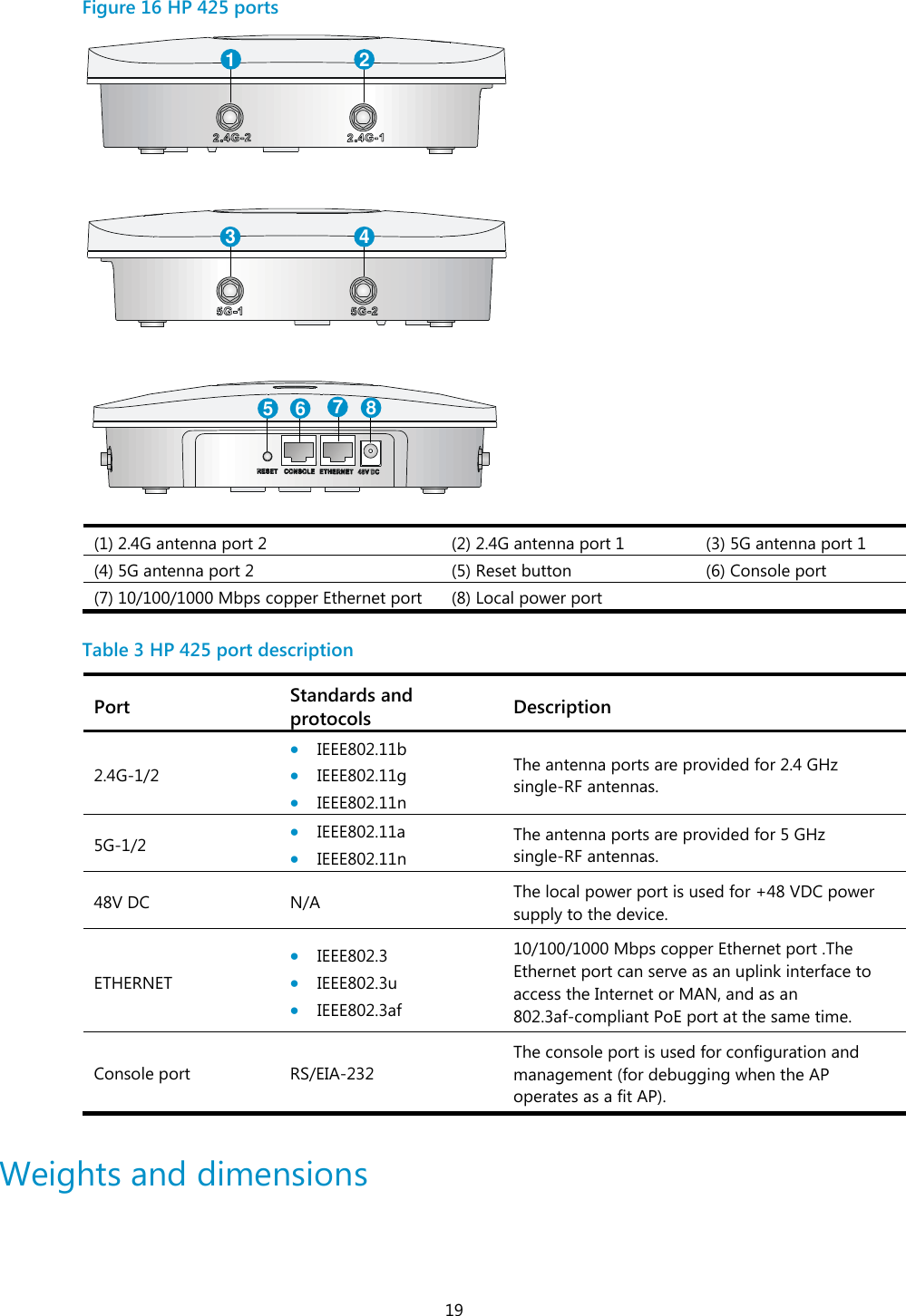
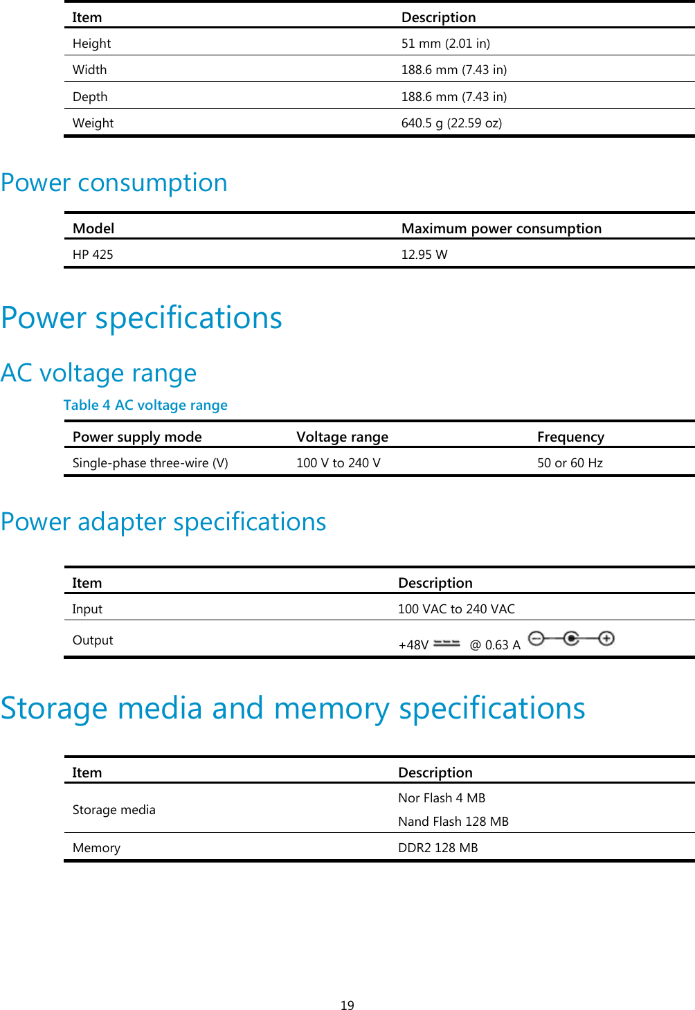
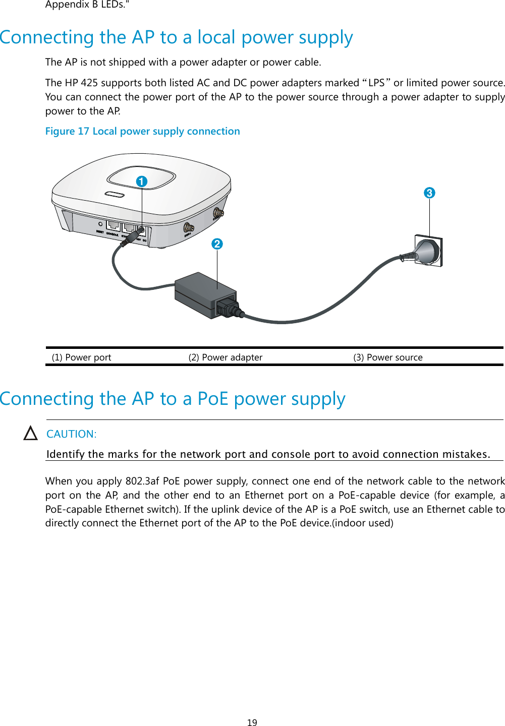
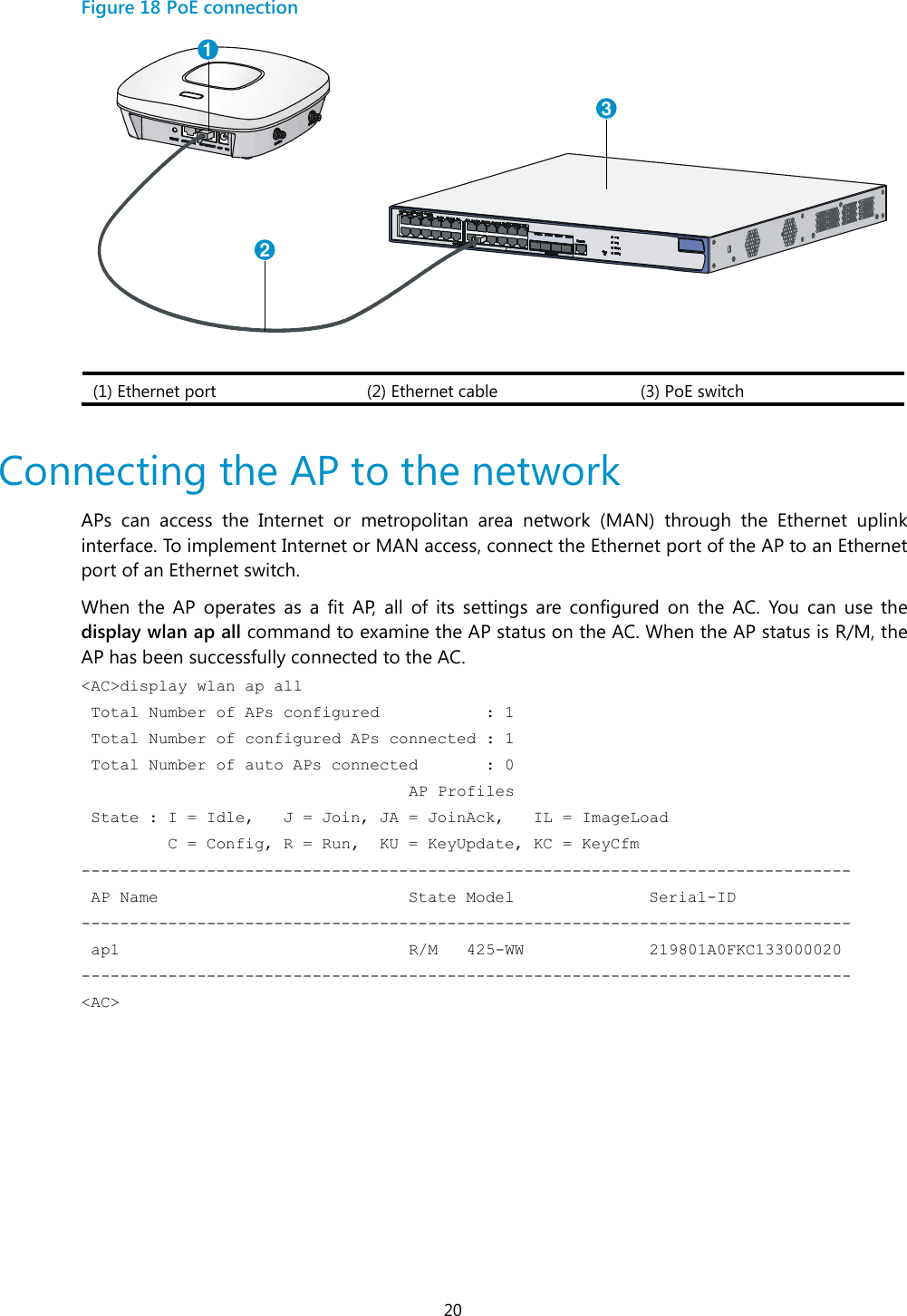
User Manual
Discussion / Help
Navigation