Hewlett Packard Enterprise BJNGAFB0004 Wireless LAN Access Point User Manual O9C BJNGAFB0004

Hewlett-Packard Company Wireless LAN Access Point O9C BJNGAFB0004

Contents

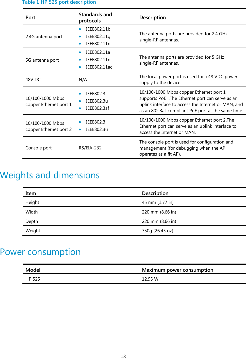
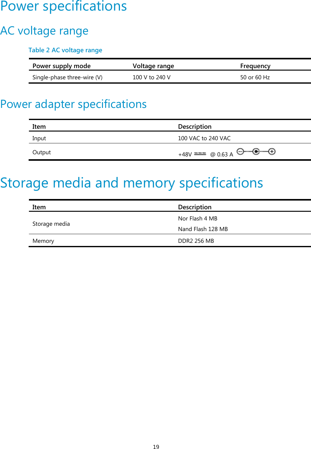
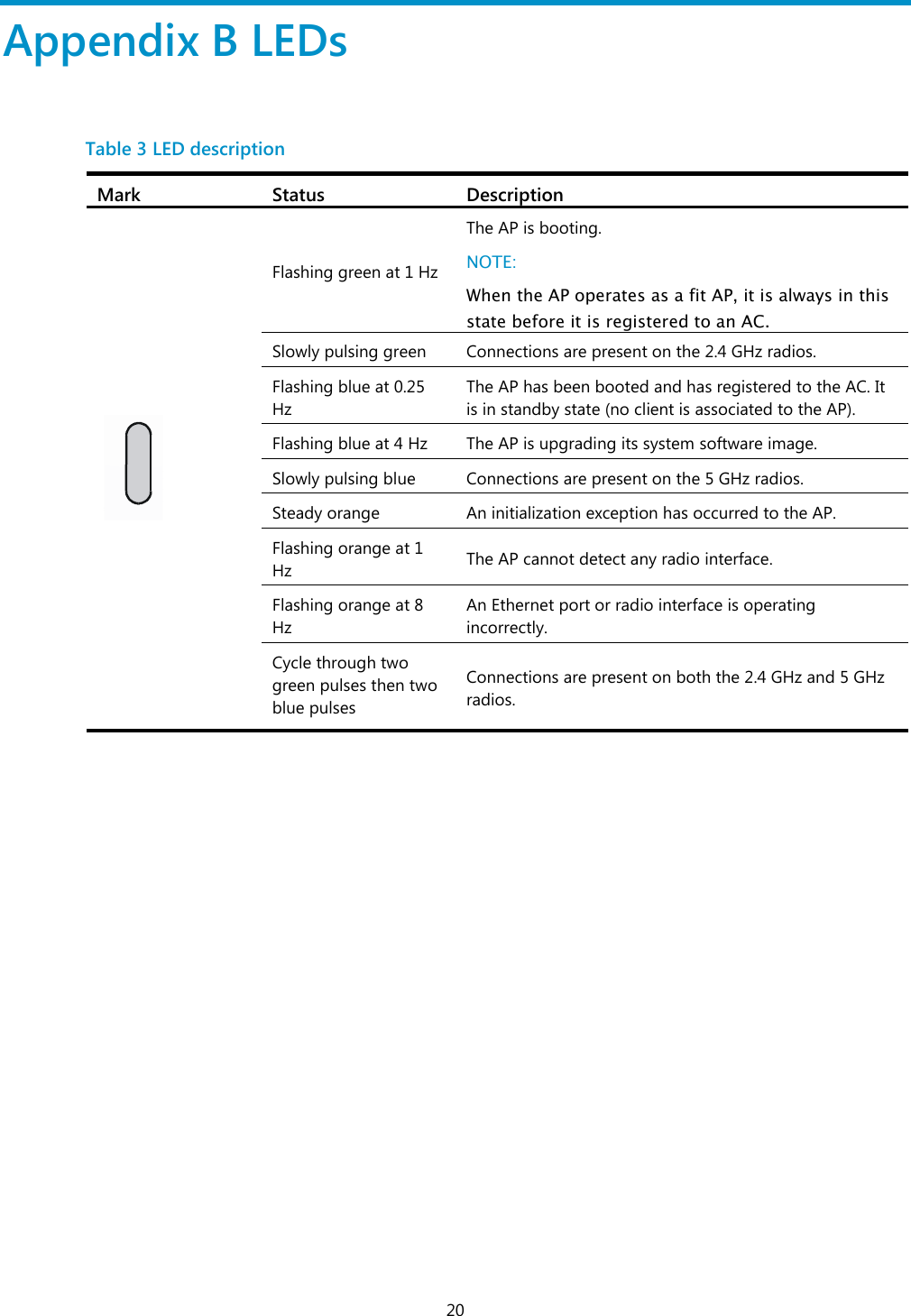
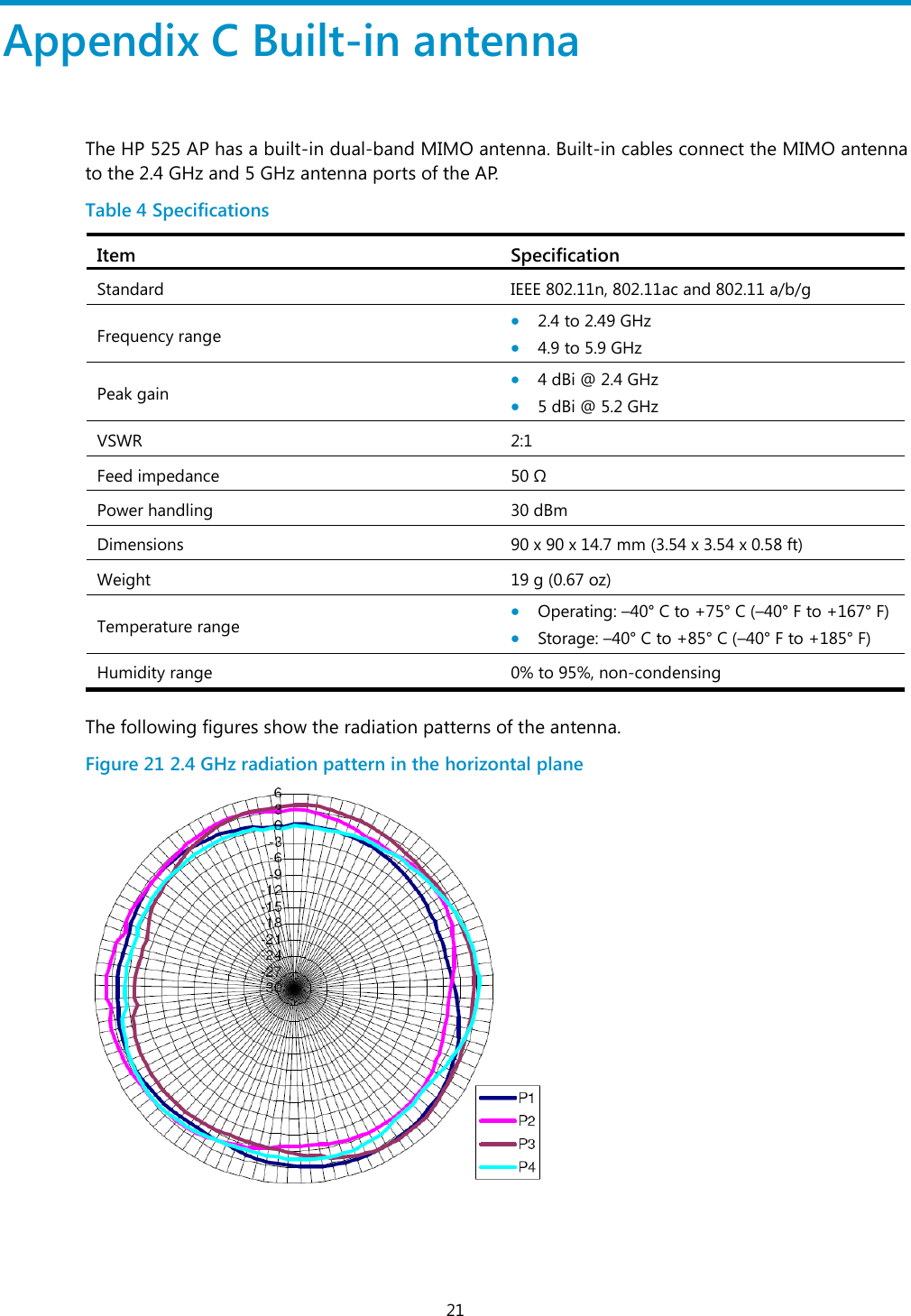
O9C-BJNGAFB0004_User Manual
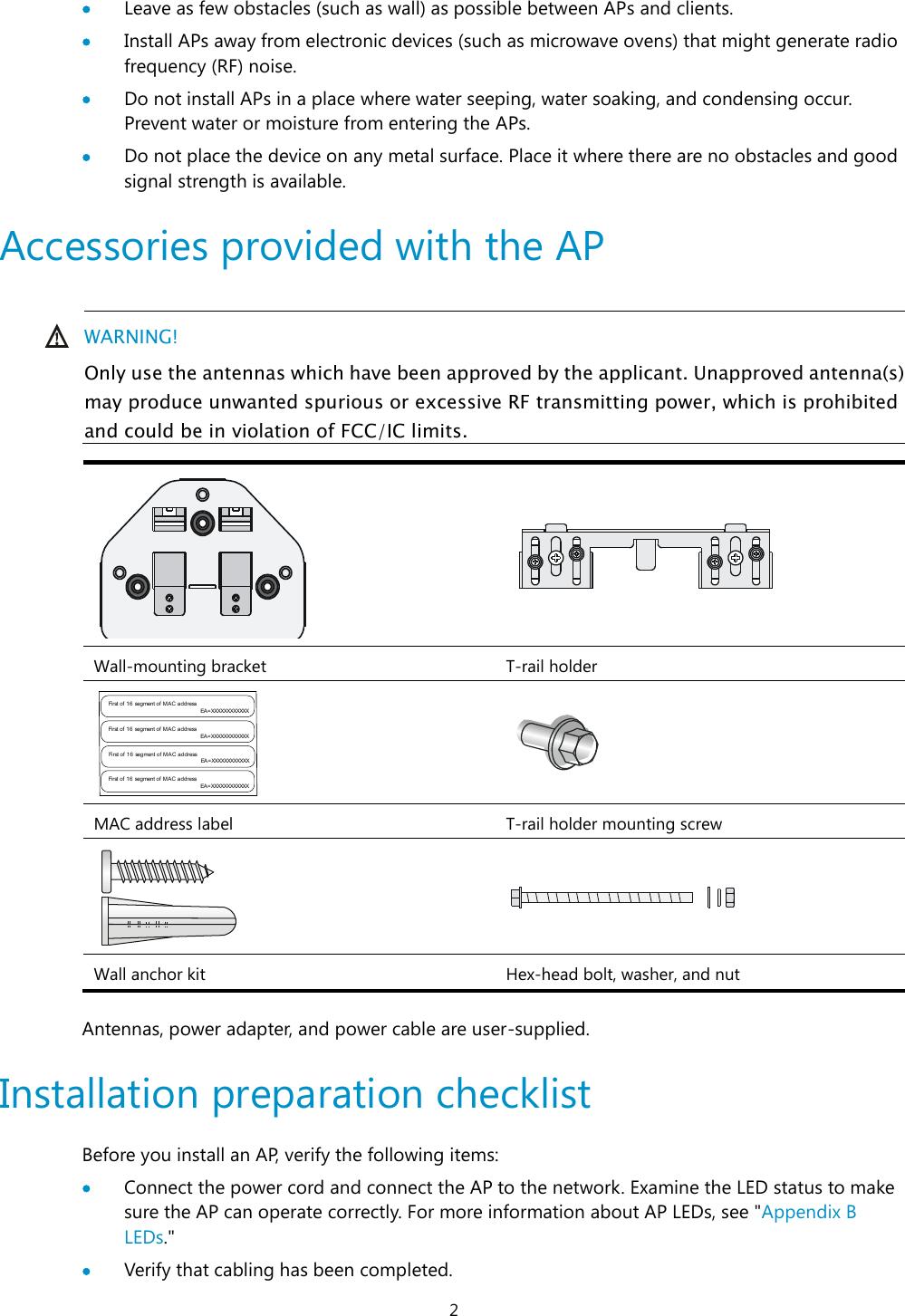
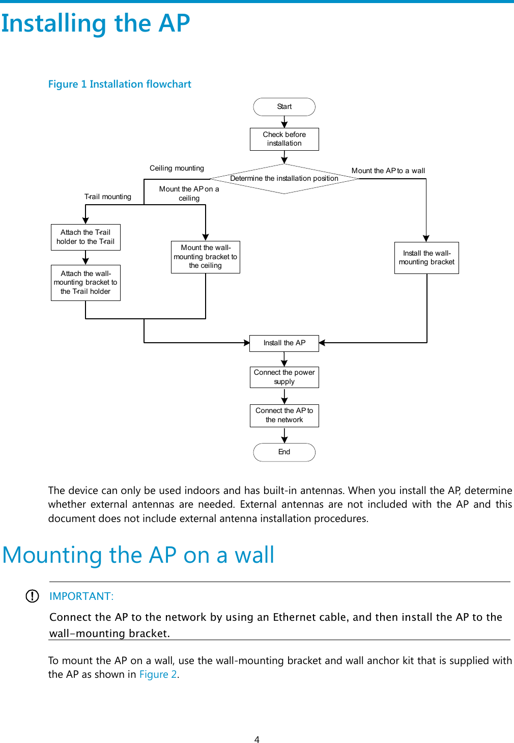
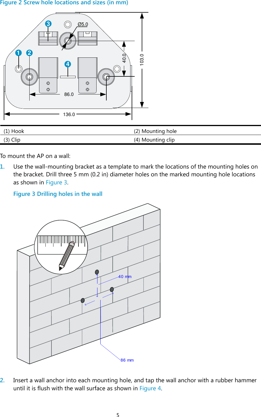
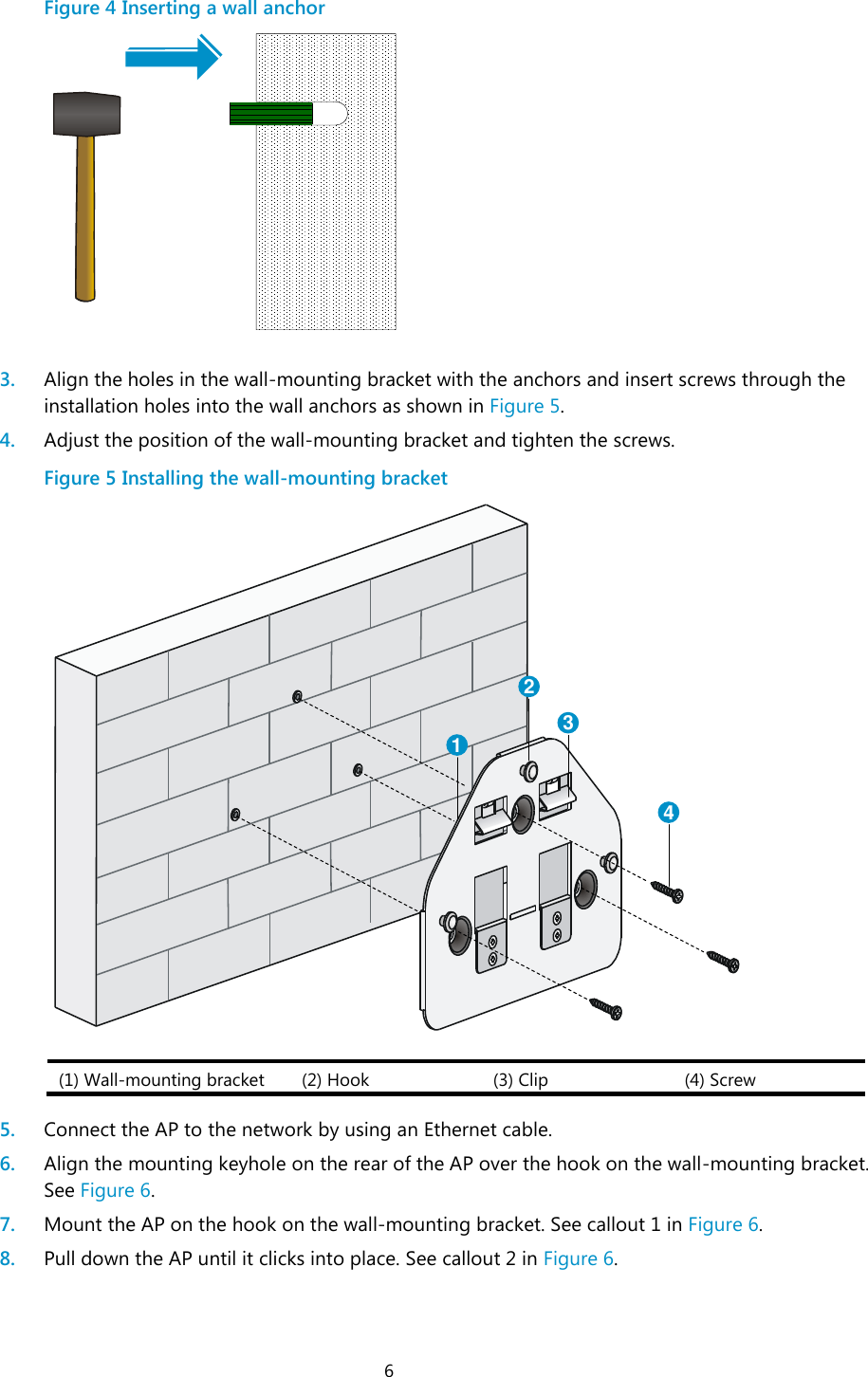
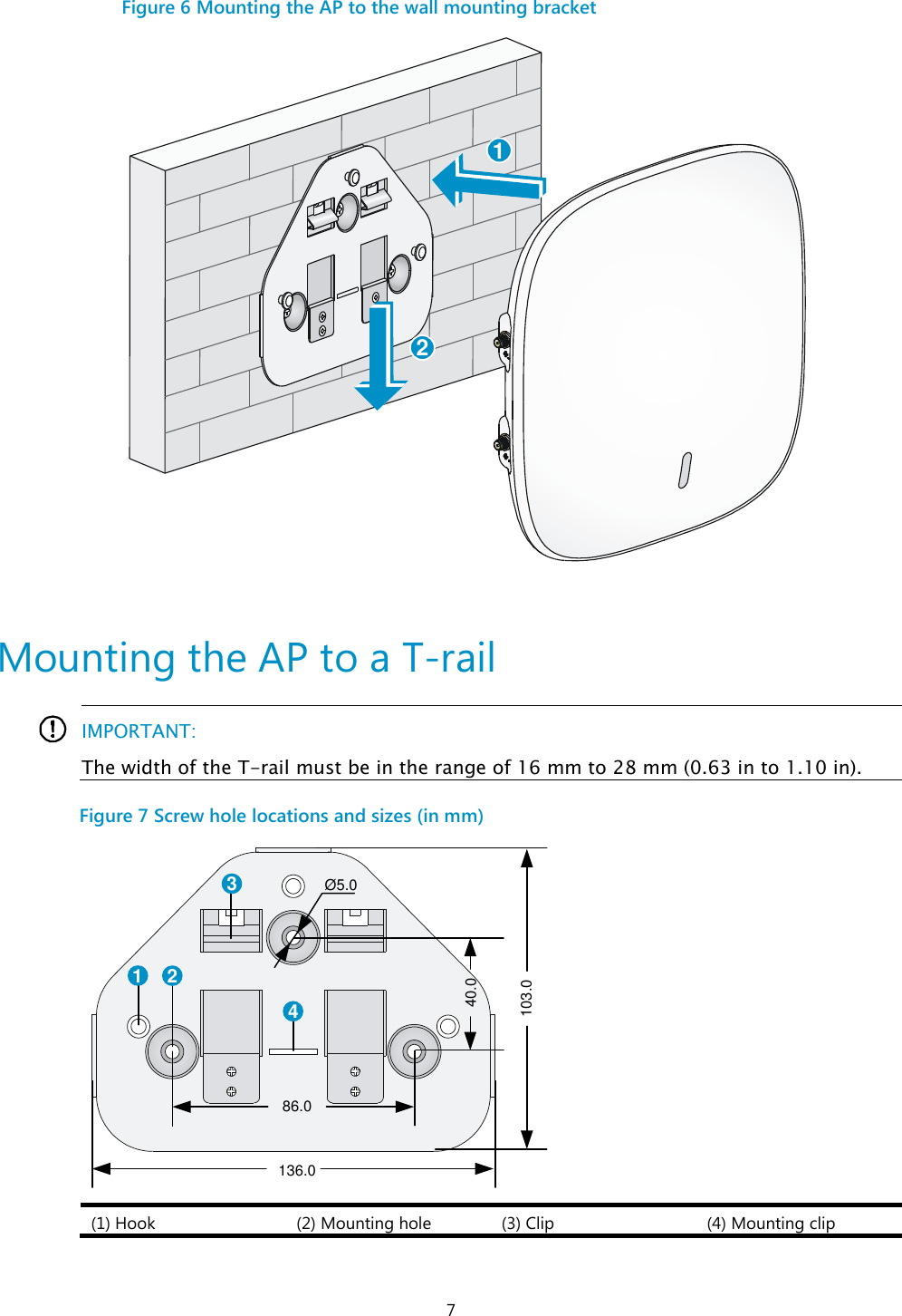
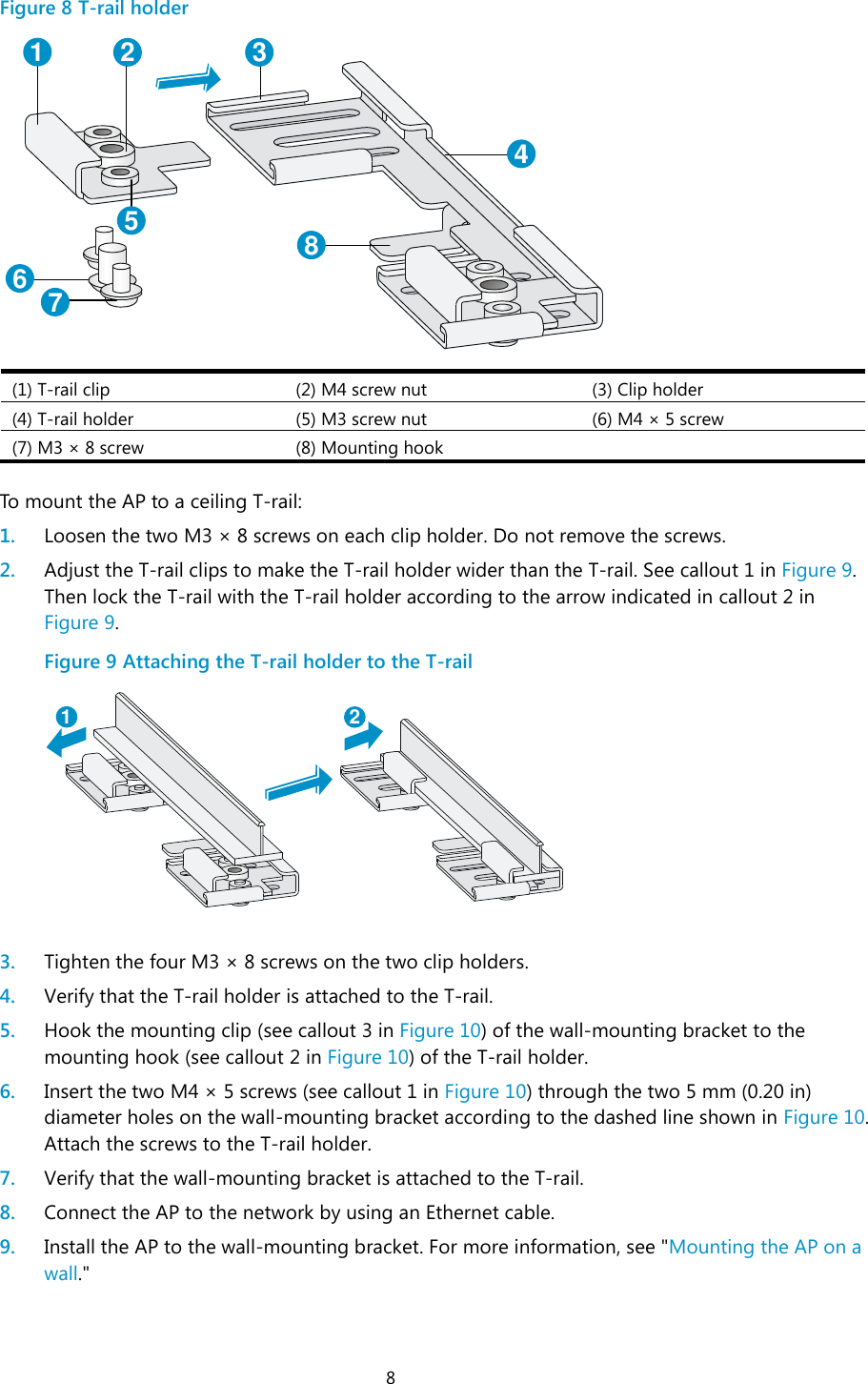
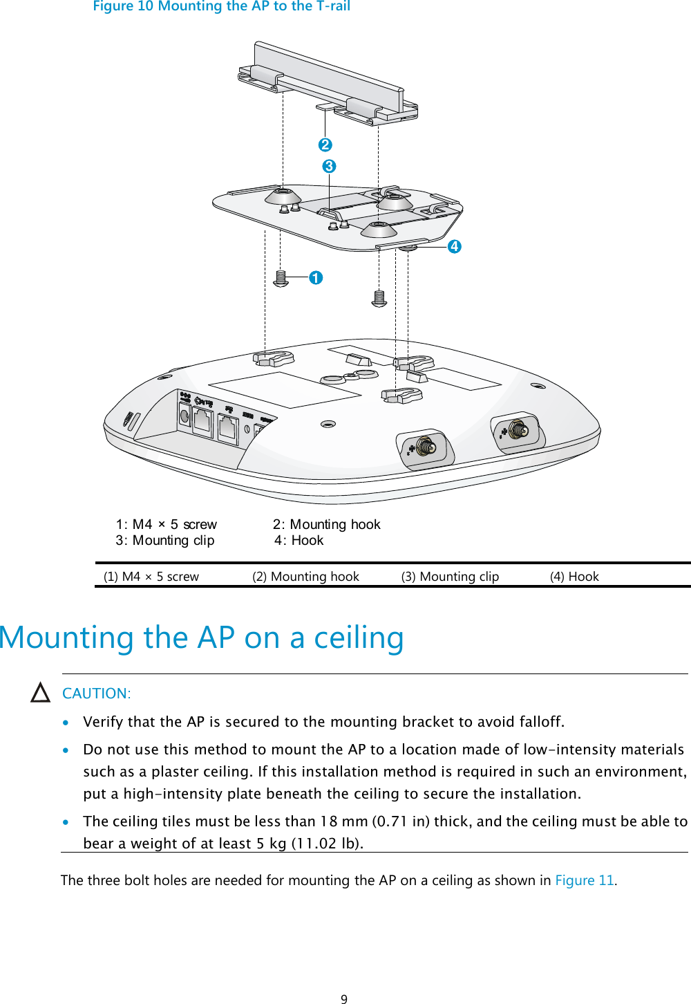
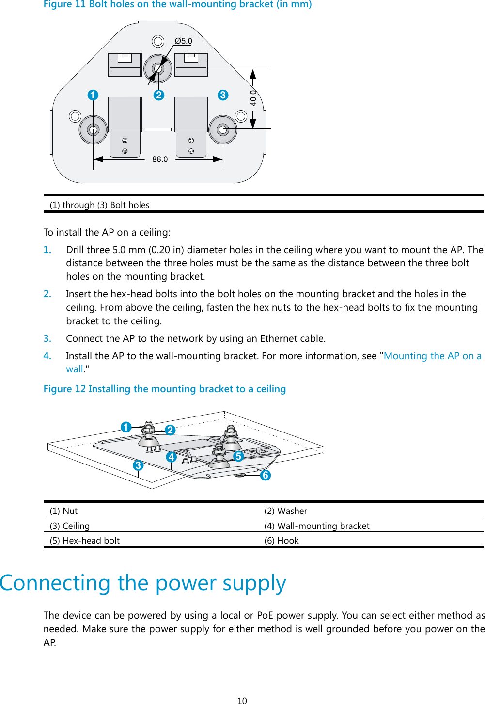
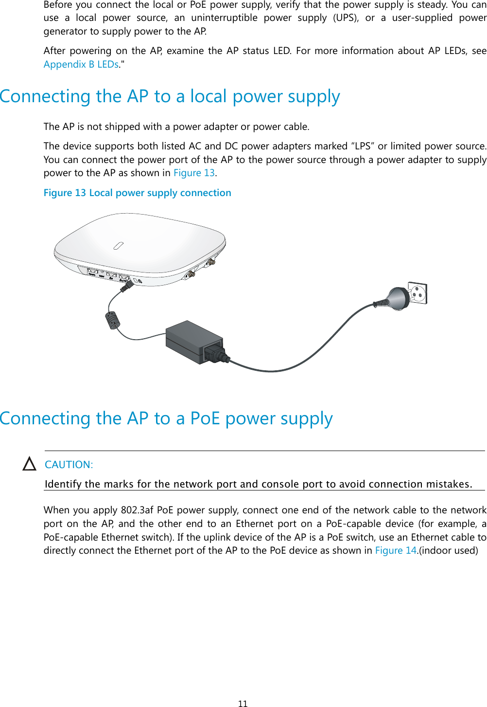
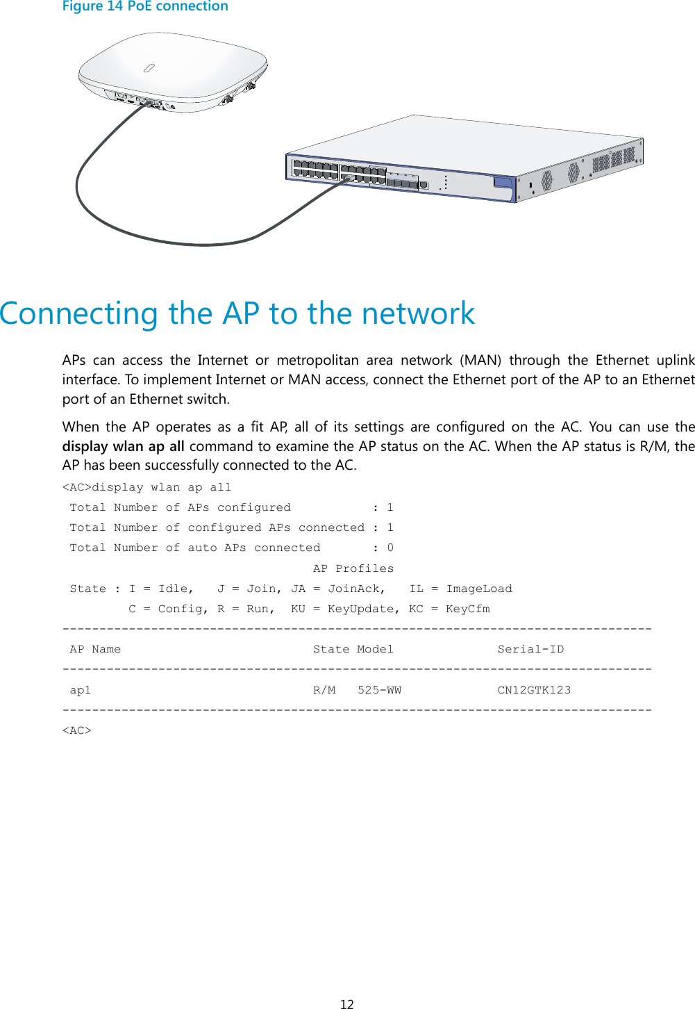
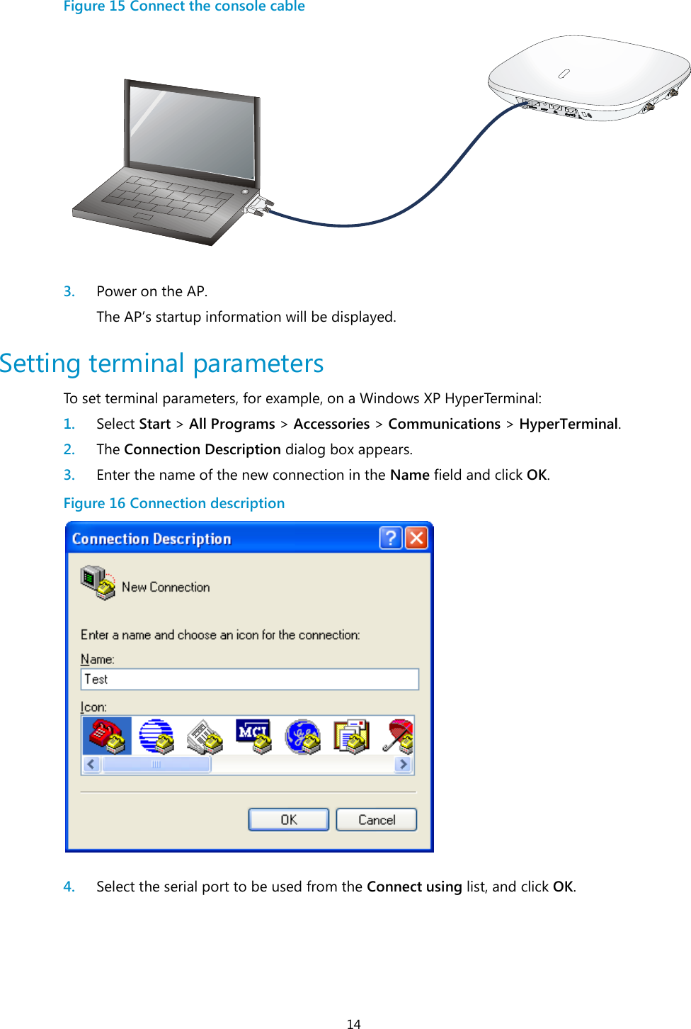
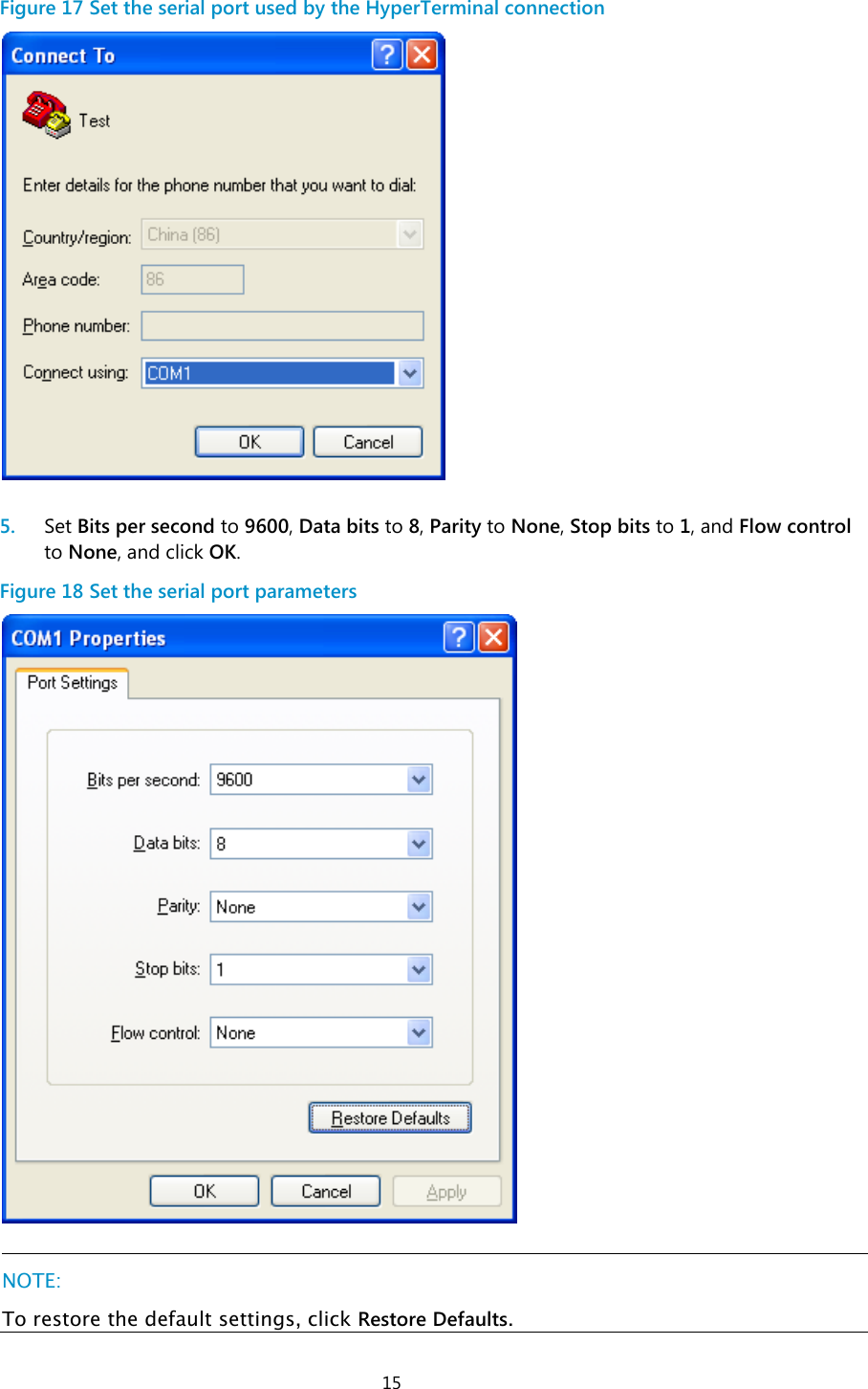
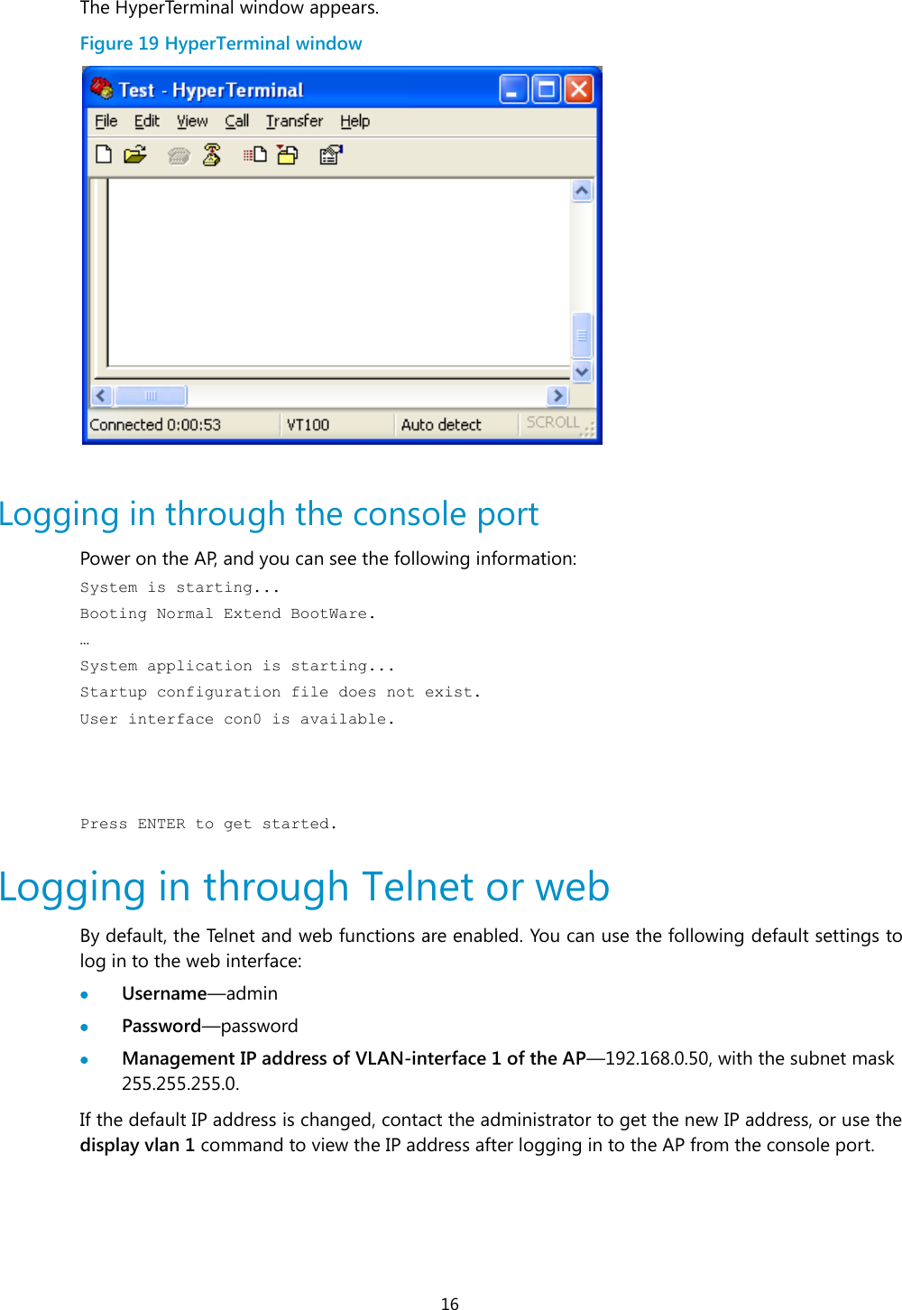
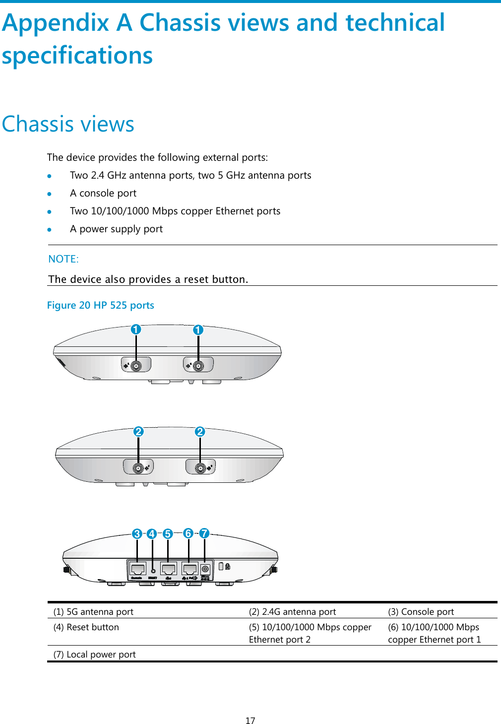
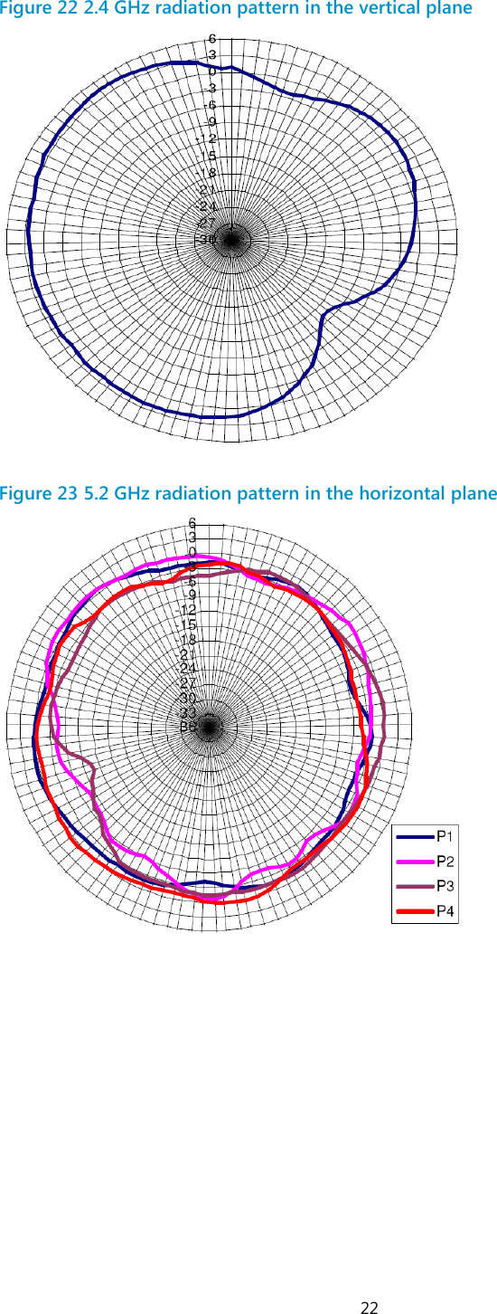
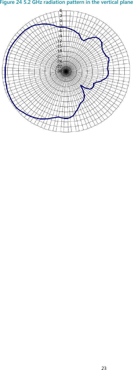
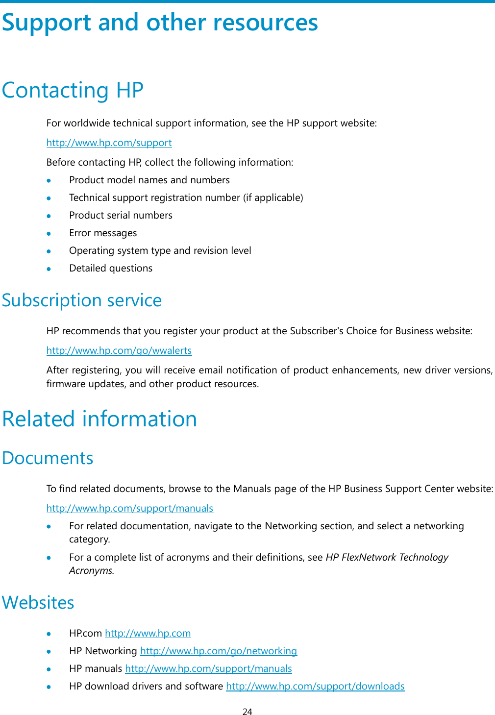
i User Manual Contents Preparing for installation ········································································································································································ 1 Safety recommendations ·········································································································································································· 1 General safety recommendations················································································································································ 1 Checking the installation site ··································································································································································· 1 Accessories provided with the AP ························································································································································· 2 Installation preparation checklist ··························································································································································· 2 Installing the AP ························································································································································································· 4 Mounting the AP on a wall ······································································································································································· 4 Mounting the AP to a T-rail ····································································································································································· 7 Mounting the AP on a ceiling ································································································································································· 9 Connecting the power supply ······························································································································································· 10 Connecting the AP to a local power supply ·························································································································· 11 Connecting the AP to a PoE power supply ···························································································································· 11 Connecting the AP to the network ······················································································································································ 12 Logging in to the fat AP ········································································································································································ 13 Logging in through the console port ················································································································································· 13 Setting up the configuration environment ···························································································································· 13 Setting terminal parameters ························································································································································ 14 Logging in through the console port ······································································································································ 16 Logging in through Telnet or web ······················································································································································ 16 Appendix A Chassis views and technical specifications ··········································································································· 17 Chassis views ································································································································································································ 17 Weights and dimensions ······························································································································································· 18 Power consumption ········································································································································································ 18 Power specifications ·················································································································································································· 19 AC voltage range ·············································································································································································· 19 Power adapter specifications ······················································································································································ 19 Storage media and memory specifications ····································································································································· 19 Appendix B LEDs ······················································································································································································ 20 Appendix C Built-in antenna ······························································································································································· 21 Support and other resources ······························································································································································ 24 Contacting HP ······························································································································································································ 24 Subscription service ········································································································································································ 24 Related information ··················································································································································································· 24 Documents ·························································································································································································· 24 Websites ······························································································································································································· 24 Conventions ·································································································································································································· 25
 1 Preparing for installation   IMPORTANT: This installation guide shows you how to install and get started using the HP 525 Wireless Dual Radio 802.11ac Access Point JG993A(AM), JG994A(WW), JG995A(JP), JG996A(IL), JG997A(8pack AW), JG998A(8pack WW), hereafter referred to as the HP 525..  Safety recommendations   WARNING!  This product is designed for specific application and needs to be installed by someone with RF and related rule knowledge. The general user shall not attempt to install or change the setting.  Before installation and operation, read all of the safety instructions in Compliance and Safety Guide supplied with your AP.  General safety recommendations To avoid possible bodily injury or equipment damage, read the following safety recommendations before  you  install  an  HP  525.  The  recommendations  do  not  cover  every  possible  hazardous condition.  Make sure the ground is dry and flat and anti-slip measures are in place.  Keep the chassis clean and dust-free.  Do not place the AP in a moist area and avoid liquid surrounding the AP.  Keep the chassis and installation tools away from walkways. Checking the installation site   WARNING! Please carefully select the installation position and make sure the final output power does not exceed the limit set forth in relevant rules. The violation of the rule could lead to serious federal penalty.  Determine the installation position by observing the following principles:  To meet regulatory RF exposure requirements, install the device at a location where the radiating antenna can be kept 40 cm (15.75 in) from any person.
 2  Leave as few obstacles (such as wall) as possible between APs and clients.  Install APs away from electronic devices (such as microwave ovens) that might generate radio frequency (RF) noise.  Do not install APs in a place where water seeping, water soaking, and condensing occur. Prevent water or moisture from entering the APs.  Do not place the device on any metal surface. Place it where there are no obstacles and good signal strength is available. Accessories provided with the AP   WARNING! Only use the antennas which have been approved by the applicant. Unapproved antenna(s) may produce unwanted spurious or excessive RF transmitting power, which is prohibited and could be in violation of FCC/IC limits.    Wall-mounting bracket T-rail holder   MAC address label T-rail holder mounting screw   Wall anchor kit Hex-head bolt, washer, and nut  Antennas, power adapter, and power cable are user-supplied. Installation preparation checklist Before you install an AP, verify the following items:  Connect the power cord and connect the AP to the network. Examine the LED status to make sure the AP can operate correctly. For more information about AP LEDs, see "Appendix B LEDs."  Verify that cabling has been completed. First of 16 segment of MAC addressEA=XXXXXXXXXXXXFirst of 16 segment of MAC addressEA=XXXXXXXXXXXXFirst of 16 segment of MAC addressEA=XXXXXXXXXXXXFirst of 16 segment of MAC addressEA=XXXXXXXXXXXX
 3  The device supports 802.3af-compliant PoE. To achieve the best performance, HP recommends that you use a GE connection to the power device.  Record the MAC address and serial number of the AP (marked on the rear of the AP) for future use.  If part of the power line is routed outdoors, use a power strip with lightning protection (user supplied) to connect the power cord of the AP to the power line.
 4 Installing the AP Figure 1 Installation flowchart    The device can only be used indoors and has built-in antennas. When you install the AP, determine whether  external  antennas  are  needed.  External  antennas  are  not  included  with  the  AP  and  this document does not include external antenna installation procedures. Mounting the AP on a wall  IMPORTANT: Connect the AP to the network by using an Ethernet cable, and then install the AP to the wall-mounting bracket.  To mount the AP on a wall, use the wall-mounting bracket and wall anchor kit that is supplied with the AP as shown in Figure 2. StartDetermine the installation positionMount the AP to a wallEndCheck before installationInstall the wall-mounting bracketCeiling mountingAttach the T-rail holder to the T-railInstall the APConnect the power supplyConnect the AP to the networkMount the wall-mounting bracket to the ceilingT-rail mountingMount the AP on a ceilingAttach the wall-mounting bracket to the T-rail holder
 5 Figure 2 Screw hole locations and sizes (in mm)  (1) Hook (2) Mounting hole (3) Clip (4) Mounting clip  To mount the AP on a wall: 1. Use the wall-mounting bracket as a template to mark the locations of the mounting holes on the bracket. Drill three 5 mm (0.2 in) diameter holes on the marked mounting hole locations as shown in Figure 3. Figure 3 Drilling holes in the wall   2. Insert a wall anchor into each mounting hole, and tap the wall anchor with a rubber hammer until it is flush with the wall surface as shown in Figure 4. 1 234Ø5.040.0103.086.0136.040 mm 86 mm
 6 Figure 4 Inserting a wall anchor   3. Align the holes in the wall-mounting bracket with the anchors and insert screws through the installation holes into the wall anchors as shown in Figure 5. 4. Adjust the position of the wall-mounting bracket and tighten the screws. Figure 5 Installing the wall-mounting bracket  (1) Wall-mounting bracket (2) Hook (3) Clip (4) Screw  5. Connect the AP to the network by using an Ethernet cable. 6. Align the mounting keyhole on the rear of the AP over the hook on the wall-mounting bracket. See Figure 6. 7. Mount the AP on the hook on the wall-mounting bracket. See callout 1 in Figure 6. 8. Pull down the AP until it clicks into place. See callout 2 in Figure 6. 1234
 7 Figure 6 Mounting the AP to the wall mounting bracket   Mounting the AP to a T-rail  IMPORTANT: The width of the T-rail must be in the range of 16 mm to 28 mm (0.63 in to 1.10 in).  Figure 7 Screw hole locations and sizes (in mm)  (1) Hook (2) Mounting hole (3) Clip (4) Mounting clip  121 234Ø5.040.0103.086.0136.0
 8 Figure 8 T-rail holder  (1) T-rail clip (2) M4 screw nut (3) Clip holder (4) T-rail holder (5) M3 screw nut (6) M4 ×  5 screw (7) M3 ×  8 screw (8) Mounting hook   To mount the AP to a ceiling T-rail: 1. Loosen the two M3 ×  8 screws on each clip holder. Do not remove the screws. 2. Adjust the T-rail clips to make the T-rail holder wider than the T-rail. See callout 1 in Figure 9. Then lock the T-rail with the T-rail holder according to the arrow indicated in callout 2 in Figure 9. Figure 9 Attaching the T-rail holder to the T-rail   3. Tighten the four M3 ×  8 screws on the two clip holders. 4. Verify that the T-rail holder is attached to the T-rail. 5. Hook the mounting clip (see callout 3 in Figure 10) of the wall-mounting bracket to the mounting hook (see callout 2 in Figure 10) of the T-rail holder. 6. Insert the two M4 ×  5 screws (see callout 1 in Figure 10) through the two 5 mm (0.20 in) diameter holes on the wall-mounting bracket according to the dashed line shown in Figure 10. Attach the screws to the T-rail holder.  7. Verify that the wall-mounting bracket is attached to the T-rail. 8. Connect the AP to the network by using an Ethernet cable. 9. Install the AP to the wall-mounting bracket. For more information, see "Mounting the AP on a wall." 1 2 3456781 2
 9 Figure 10 Mounting the AP to the T-rail  (1) M4 × 5 screw (2) Mounting hook  (3) Mounting clip  (4) Hook   Mounting the AP on a ceiling  CAUTION:  Verify that the AP is secured to the mounting bracket to avoid falloff.  Do not use this method to mount the AP to a location made of low-intensity materials such as a plaster ceiling. If this installation method is required in such an environment, put a high-intensity plate beneath the ceiling to secure the installation.  The ceiling tiles must be less than 18 mm (0.71 in) thick, and the ceiling must be able to bear a weight of at least 5 kg (11.02 lb).  The three bolt holes are needed for mounting the AP on a ceiling as shown in Figure 11. 1: M4 × 5 screw             2: Mounting hook3: Mounting clip              4: Hook 1234
 10 Figure 11 Bolt holes on the wall-mounting bracket (in mm)  (1) through (3) Bolt holes  To install the AP on a ceiling: 1. Drill three 5.0 mm (0.20 in) diameter holes in the ceiling where you want to mount the AP. The distance between the three holes must be the same as the distance between the three bolt holes on the mounting bracket. 2. Insert the hex-head bolts into the bolt holes on the mounting bracket and the holes in the ceiling. From above the ceiling, fasten the hex nuts to the hex-head bolts to fix the mounting bracket to the ceiling. 3. Connect the AP to the network by using an Ethernet cable. 4. Install the AP to the wall-mounting bracket. For more information, see "Mounting the AP on a wall." Figure 12 Installing the mounting bracket to a ceiling  (1) Nut (2) Washer (3) Ceiling (4) Wall-mounting bracket (5) Hex-head bolt (6) Hook  Connecting the power supply The device can be powered by using a local or PoE power supply. You can select either method as needed. Make sure the power supply for either method is well grounded before you power on the AP. Ø5.040.0186.02 3312456
 11 Before you connect the local or PoE power supply, verify that the power supply is steady. You can use  a  local  power  source,  an  uninterruptible  power  supply  (UPS),  or  a  user-supplied  power generator to supply power to the AP. After powering on  the AP, examine the  AP status  LED.  For more information  about AP LEDs,  see Appendix B LEDs." Connecting the AP to a local power supply The AP is not shipped with a power adapter or power cable. The device supports both listed AC and DC power adapters marked “LPS” or limited power source. You can connect the power port of the AP to the power source through a power adapter to supply power to the AP as shown in Figure 13. Figure 13 Local power supply connection      Connecting the AP to a PoE power supply   CAUTION: Identify the marks for the network port and console port to avoid connection mistakes.  When you apply 802.3af PoE power supply, connect one end of the network cable to the network port on  the  AP,  and  the  other end  to  an  Ethernet port on  a  PoE-capable  device (for  example,  a PoE-capable Ethernet switch). If the uplink device of the AP is a PoE switch, use an Ethernet cable to directly connect the Ethernet port of the AP to the PoE device as shown in Figure 14.(indoor used)
 12 Figure 14 PoE connection    Connecting the AP to the network APs  can  access  the  Internet  or  metropolitan  area  network  (MAN)  through  the  Ethernet  uplink interface. To implement Internet or MAN access, connect the Ethernet port of the AP to an Ethernet port of an Ethernet switch. When  the  AP  operates  as  a  fit  AP,  all  of  its  settings  are  configured  on  the  AC.  You  can  use  the display wlan ap all command to examine the AP status on the AC. When the AP status is R/M, the AP has been successfully connected to the AC. <AC>display wlan ap all                                                           Total Number of APs configured           : 1                                     Total Number of configured APs connected : 1                                     Total Number of auto APs connected       : 0                                                                      AP Profiles                                     State : I = Idle,   J = Join, JA = JoinAck,   IL = ImageLoad                             C = Config, R = Run,  KU = KeyUpdate, KC = KeyCfm                       --------------------------------------------------------------------------------  AP Name                          State Model              Serial-ID             --------------------------------------------------------------------------------  ap1                              R/M   525-WW             CN12GTK123 -------------------------------------------------------------------------------- <AC>
 13 Logging in to the fat AP  NOTE: The HP 525 is usually installed on a high position. HP recommends that you log in to the AP to configure related settings before you install the AP.  When  the  HP  525  operates  as  a  fat  AP,  you  can  log  in  to  the  AP  through  the  console  port,  or through Telnet or web to configure the AP, but you must obtain the IP address of the AP first.  Logging in through the console port—Logging in through the console port is the most fundamental login method. To log in through other methods, you must log in through the console port and perform the required configurations.  Logging in through Telnet—You can telnet to the device to remotely manage and maintain it.  Logging in through web—You can log in to the web interface of the device to remotely manage and maintain it. Logging in through the console port  Prepare the following before you log in through the console port:  An 8-core shielded console cable, with a crimped RJ-45 connector at one end, and a DB-9 female connector at the other end.  A configuration terminal—A laptop or PC with a serial port. Setting up the configuration environment   NOTE: The serial ports on PCs do not support hot swapping. If the AP has been powered on, connect the console cable to the PC before connecting to the AP, and when you disconnect the cable, first disconnect from the AP.  To connect the console cable: 1. Plug the DB-9 female connector to the serial port of the PC. 2. Connect the RJ-45 connector to the console port of the AP.
 14 Figure 15 Connect the console cable   3. Power on the AP. The AP’s startup information will be displayed. Setting terminal parameters To set terminal parameters, for example, on a Windows XP HyperTerminal: 1. Select Start > All Programs > Accessories > Communications > HyperTerminal. 2. The Connection Description dialog box appears.  3. Enter the name of the new connection in the Name field and click OK. Figure 16 Connection description   4. Select the serial port to be used from the Connect using list, and click OK.
 15 Figure 17 Set the serial port used by the HyperTerminal connection   5. Set Bits per second to 9600, Data bits to 8, Parity to None, Stop bits to 1, and Flow control to None, and click OK. Figure 18 Set the serial port parameters    NOTE: To restore the default settings, click Restore Defaults.
 16 The HyperTerminal window appears. Figure 19 HyperTerminal window   Logging in through the console port Power on the AP, and you can see the following information: System is starting... Booting Normal Extend BootWare. … System application is starting... Startup configuration file does not exist. User interface con0 is available.    Press ENTER to get started. Logging in through Telnet or web By default, the Telnet and web functions are enabled. You can use the following default settings to log in to the web interface:  Username—admin  Password—password  Management IP address of VLAN-interface 1 of the AP—192.168.0.50, with the subnet mask 255.255.255.0. If the default IP address is changed, contact the administrator to get the new IP address, or use the display vlan 1 command to view the IP address after logging in to the AP from the console port.
 17 Appendix A Chassis views and technical specifications Chassis views The device provides the following external ports:  Two 2.4 GHz antenna ports, two 5 GHz antenna ports  A console port  Two 10/100/1000 Mbps copper Ethernet ports  A power supply port   NOTE: The device also provides a reset button.  Figure 20 HP 525 ports   (1) 5G antenna port (2) 2.4G antenna port (3) Console port  (4) Reset button  (5) 10/100/1000 Mbps copper Ethernet port 2 (6) 10/100/1000 Mbps copper Ethernet port 1 (7) Local power port    11223456 7
 18 Table 1 HP 525 port description Port Standards and protocols Description 2.4G antenna port  IEEE802.11b  IEEE802.11g  IEEE802.11n The antenna ports are provided for 2.4 GHz single-RF antennas. 5G antenna port  IEEE802.11a  IEEE802.11n  IEEE802.11ac The antenna ports are provided for 5 GHz single-RF antennas. 48V DC N/A The local power port is used for +48 VDC power supply to the device. 10/100/1000 Mbps copper Ethernet port 1  IEEE802.3  IEEE802.3u  IEEE802.3af 10/100/1000 Mbps copper Ethernet port 1 supports PoE  .The Ethernet port can serve as an uplink interface to access the Internet or MAN, and as an 802.3af-compliant PoE port at the same time. 10/100/1000 Mbps copper Ethernet port 2  IEEE802.3  IEEE802.3u 10/100/1000 Mbps copper Ethernet port 2.The Ethernet port can serve as an uplink interface to access the Internet or MAN. Console port RS/EIA-232 The console port is used for configuration and management (for debugging when the AP operates as a fit AP).  Weights and dimensions Item Description Height 45 mm (1.77 in) Width 220 mm (8.66 in) Depth 220 mm (8.66 in) Weight 750g (26.45 oz)  Power consumption Model Maximum power consumption HP 525 12.95 W
 19 Power specifications AC voltage range Table 2 AC voltage range Power supply mode Voltage range Frequency Single-phase three-wire (V) 100 V to 240 V 50 or 60 Hz  Power adapter specifications Item Description Input 100 VAC to 240 VAC Output +48V  @ 0.63 A    Storage media and memory specifications Item Description Storage media Nor Flash 4 MB Nand Flash 128 MB Memory DDR2 256 MB
 20 Appendix B LEDs Table 3 LED description Mark Status Description   Flashing green at 1 Hz  The AP is booting. NOTE: When the AP operates as a fit AP, it is always in this state before it is registered to an AC. Slowly pulsing green Connections are present on the 2.4 GHz radios. Flashing blue at 0.25 Hz The AP has been booted and has registered to the AC. It is in standby state (no client is associated to the AP). Flashing blue at 4 Hz The AP is upgrading its system software image. Slowly pulsing blue Connections are present on the 5 GHz radios. Steady orange An initialization exception has occurred to the AP. Flashing orange at 1 Hz The AP cannot detect any radio interface. Flashing orange at 8 Hz An Ethernet port or radio interface is operating incorrectly. Cycle through two green pulses then two blue pulses  Connections are present on both the 2.4 GHz and 5 GHz radios.
 21 Appendix C Built-in antenna The HP 525 AP has a built-in dual-band MIMO antenna. Built-in cables connect the MIMO antenna to the 2.4 GHz and 5 GHz antenna ports of the AP. Table 4 Specifications Item  Specification Standard  IEEE 802.11n, 802.11ac and 802.11 a/b/g Frequency range  2.4 to 2.49 GHz  4.9 to 5.9 GHz Peak gain  4 dBi @ 2.4 GHz  5 dBi @ 5.2 GHz VSWR  2:1 Feed impedance  50 Ω Power handling  30 dBm Dimensions  90 x 90 x 14.7 mm (3.54 x 3.54 x 0.58 ft) Weight  19 g (0.67 oz) Temperature range  Operating: –40° C to +75° C (–40° F to +167° F)  Storage: –40° C to +85° C (–40° F to +185° F) Humidity range  0% to 95%, non-condensing  The following figures show the radiation patterns of the antenna. Figure 21 2.4 GHz radiation pattern in the horizontal plane
 22 Figure 22 2.4 GHz radiation pattern in the vertical plane   Figure 23 5.2 GHz radiation pattern in the horizontal plane
 23 Figure 24 5.2 GHz radiation pattern in the vertical plane
 24 Support and other resources Contacting HP For worldwide technical support information, see the HP support website: http://www.hp.com/support Before contacting HP, collect the following information:  Product model names and numbers  Technical support registration number (if applicable)  Product serial numbers  Error messages  Operating system type and revision level  Detailed questions Subscription service HP recommends that you register your product at the Subscriber's Choice for Business website: http://www.hp.com/go/wwalerts After registering, you will receive email notification of product enhancements, new driver versions, firmware updates, and other product resources. Related information Documents To find related documents, browse to the Manuals page of the HP Business Support Center website: http://www.hp.com/support/manuals  For related documentation, navigate to the Networking section, and select a networking category.  For a complete list of acronyms and their definitions, see HP FlexNetwork Technology Acronyms. Websites  HP.com http://www.hp.com  HP Networking http://www.hp.com/go/networking  HP manuals http://www.hp.com/support/manuals  HP download drivers and software http://www.hp.com/support/downloads
 25  HP software depot http://www.software.hp.com  HP Education http://www.hp.com/learn Conventions This section describes the conventions used in this documentation set. Command conventions Convention Description Boldface Bold text represents commands and keywords that you enter literally as shown. Italic Italic text represents arguments that you replace with actual values. [ ] Square brackets enclose syntax choices (keywords or arguments) that are optional. { x | y | ... } Braces enclose a set of required syntax choices separated by vertical bars, from which you select one.  [ x | y | ... ] Square brackets enclose a set of optional syntax choices separated by vertical bars, from which you select one or none.  { x | y | ... } * Asterisk-marked braces enclose a set of required syntax choices separated by vertical bars, from which you select at least one. [ x | y | ... ] * Asterisk-marked square brackets enclose optional syntax choices separated by vertical bars, from which you select one choice, multiple choices, or none.  &<1-n> The argument or keyword and argument combination before the ampersand (&) sign can be entered 1 to n times. # A line that starts with a pound (#) sign is comments.  GUI conventions Convention Description Boldface Window names, button names, field names, and menu items are in bold text. For example, the New User window appears; click OK. > Multi-level menus are separated by angle brackets. For example, File > Create > Folder.  Symbols Convention Description  WARNING An alert that calls attention to important information that if not understood or followed can result in personal injury.  CAUTION An alert that calls attention to important information that if not understood or followed can result in data loss, data corruption, or damage to hardware or software.   IMPORTANT An alert that calls attention to essential information. NOTE An alert that contains additional or supplementary information.  TIP An alert that provides helpful information.
 26 Network topology icons  Represents a generic network device, such as a router, switch, or firewall.  Represents a routing-capable device, such as a router or Layer 3 switch.  Represents a generic switch, such as a Layer 2 or Layer 3 switch, or a router that supports Layer 2 forwarding and other Layer 2 features.  Represents an access controller, a unified wired-WLAN module, or the switching engine on a unified wired-WLAN switch.  Represents an access point.  Port numbering in examples The  port  numbers  in  this  document  are  for  illustration  only  and  might  be  unavailable  on  your device.
1 HP MIMO S2451DBTH33RSM2x2 Dual Bands MIMO Antenna2.4-2.5GHz; 4.9-5.875GHzHP Part No: JG696AAppendix C Built-in antennaAppendix C Built-in antennaAppendix C Built-in antennaAppendix C Built-in antennaAppendix D External Antenna
Gain & Efficiency Summary –Low Band6EfficiencyMax GainMax Gain Average Gain Ripple Max Gain Average Gain Max Gain Average Gain2400 76% 3.67 1.67 -0.63 7.16 1.14 -2.15 1.03 -3.302410 77% 3.38 1.28 -0.61 5.50 1.65 -1.79 0.30 -3.172420 79% 3.09 1.19 -0.46 4.99 1.93 -1.47 0.76 -3.052430 80% 2.79 1.07 -0.39 4.41 1.95 -1.45 1.06 -3.072440 79% 2.93 1.06 -0.31 3.88 1.78 -1.65 1.08 -3.182450 78% 3.48 1.37 -0.27 4.13 1.43 -2.22 1.03 -3.212460 78% 3.96 1.73 -0.22 4.65 0.55 -2.80 0.89 -3.132470 78% 4.12 1.95 -0.16 4.73 -0.06 -2.95 0.65 -3.142480 77% 3.98 1.87 -0.25 5.15 -0.47 -2.93 1.36 -2.982490 77% 3.64 1.69 -0.42 5.26 0.11 -2.62 1.54 -2.802500 76% 3.25 1.45 -0.63 6.14 0.80 -2.20 1.42 -2.65Frequency (MHz)3D Elevation 0°Azimuth Elevation 90°L1 BeforeL1 After EfficiencyMax GainMax Gain Average Gain Ripple Max Gain Average Gain Max Gain Average Gain2400 76% 3.20 1.45 -0.69 4.24 1.78 -2.15 -0.20 -3.212410 76% 3.15 1.37 -0.69 4.12 2.06 -1.93 0.12 -3.102420 79% 3.08 1.24 -0.60 3.54 2.21 -1.64 0.60 -2.922430 79% 2.81 0.88 -0.60 3.43 2.12 -1.55 0.89 -2.922440 78% 2.58 0.59 -0.57 3.31 1.90 -1.58 0.99 -3.002450 77% 2.89 0.79 -0.52 3.18 1.44 -1.86 1.13 -2.982460 78% 3.17 1.20 -0.47 3.53 0.87 -2.20 1.23 -3.002470 77% 3.10 1.41 -0.49 4.11 1.23 -2.31 0.86 -3.032480 77% 3.24 1.45 -0.53 4.51 1.57 -2.34 0.62 -3.022490 76% 3.31 1.48 -0.57 4.67 1.92 -2.25 0.57 -2.982500 76% 3.32 1.41 -0.65 4.47 2.26 -2.04 0.60 -2.95Frequency (MHz)3D Azimuth Elevation 0° Elevation 90°
Gain & Efficiency Summary –Low Band7L2 BeforeL2 AfterEfficiencyMax GainMax Gain Average Gain Ripple Max Gain Average Gain Max Gain Average Gain2400 76% 2.78 1.29 -0.61 6.43 2.29 -2.17 1.79 -1.972410 76% 2.61 1.05 -0.67 5.19 2.14 -2.32 1.92 -1.842420 79% 2.60 0.82 -0.52 3.60 1.96 -2.27 1.96 -1.752430 79% 2.37 0.85 -0.43 3.49 1.61 -2.21 1.82 -1.872440 80% 2.52 0.90 -0.27 3.47 1.40 -1.97 1.55 -2.062450 80% 3.05 1.60 -0.16 3.82 2.00 -1.65 1.32 -2.242460 80% 3.47 1.87 -0.18 3.98 1.83 -1.53 1.79 -2.162470 80% 3.51 1.89 -0.14 4.57 2.09 -1.42 1.75 -2.192480 78% 3.43 1.68 -0.30 5.24 2.36 -1.61 2.04 -2.062490 77% 3.30 1.39 -0.51 6.29 2.49 -1.88 2.35 -1.892500 77% 3.05 1.32 -0.72 6.69 2.52 -2.09 2.46 -1.783DFrequency (MHz)Azimuth Elevation 0° Elevation 90°EfficiencyMax GainMax Gain Average Gain Ripple Max Gain Average Gain Max Gain Average Gain2400 77% 3.68 1.60 -0.59 4.61 0.70 -2.21 -0.06 -2.992410 77% 3.30 1.28 -0.70 4.17 0.73 -2.01 0.58 -2.932420 78% 2.91 0.92 -0.59 3.75 1.38 -1.88 1.03 -2.812430 79% 2.42 1.30 -0.52 3.65 1.72 -1.99 1.03 -2.802440 80% 2.40 1.61 -0.43 3.87 1.83 -2.06 0.81 -2.802450 80% 2.91 1.76 -0.42 4.53 1.34 -2.33 0.34 -2.852460 80% 3.41 1.78 -0.51 5.35 0.67 -2.52 0.37 -2.842470 79% 3.65 1.55 -0.54 5.23 0.39 -2.49 0.34 -2.872480 78% 3.78 1.20 -0.64 5.06 0.31 -2.49 0.59 -2.832490 77% 3.83 1.23 -0.75 5.15 0.51 -2.40 0.89 -2.802500 77% 3.73 1.23 -0.86 5.13 0.72 -2.23 1.13 -2.77Azimuth Elevation 0° Elevation 90°3DFrequency (MHz)
Gain & Efficiency Summary –High Band8H1 BeforeH1 AfterEfficiencyMax GainMax Gain Average Gain Ripple Max Gain Average Gain Max Gain Average Gain4900 53% 4.69 0.28 -2.89 7.74 -0.11 -5.00 4.63 -1.165150 53% 5.07 -0.22 -3.12 10.94 -1.12 -5.06 5.01 -1.175350 56% 5.65 0.40 -2.93 13.96 0.38 -4.72 5.61 -1.285470 55% 5.47 0.61 -2.97 18.04 0.59 -4.80 5.46 -1.645725 59% 5.45 1.90 -2.44 19.70 0.54 -4.76 5.45 -1.885825 60% 5.32 2.04 -2.33 20.23 0.52 -5.00 5.32 -1.985875 57% 5.33 1.53 -2.66 24.27 -0.85 -5.56 5.31 -2.28Frequency (MHz)3D Elevation 0°Azimuth Elevation 90°EfficiencyMax GainMax Gain Average Gain Ripple Max Gain Average Gain Max Gain Average Gain4900 55% 4.42 0.54 -2.64 7.87 0.72 -4.27 4.02 -1.585150 53% 4.31 0.32 -3.08 10.07 1.68 -4.62 3.81 -1.785350 56% 4.29 0.98 -2.81 11.67 2.33 -4.70 4.10 -1.815470 52% 3.98 0.38 -3.07 11.83 1.76 -5.26 3.75 -2.285725 54% 4.44 1.25 -2.77 15.50 -0.02 -5.42 3.54 -2.595825 55% 4.61 1.84 -2.78 16.31 -0.74 -5.59 3.33 -2.565875 51% 4.05 1.24 -3.26 14.65 -0.95 -6.32 3.11 -2.86Frequency (MHz)3D Azimuth Elevation 0° Elevation 90°
Gain & Efficiency Summary –High Band9H2 BeforeH2 AfterEfficiencyMax GainMax Gain Average Gain Ripple Max Gain Average Gain Max Gain Average Gain4900 67% 6.06 0.82 -1.94 6.66 2.16 -3.24 5.71 -0.275150 64% 6.21 0.51 -2.11 11.08 0.71 -4.74 5.84 -0.445350 64% 6.13 0.93 -2.09 15.29 -0.47 -5.73 5.89 -0.725470 64% 5.86 0.83 -2.22 16.95 -0.88 -5.78 5.68 -0.905725 64% 5.19 1.50 -2.24 20.02 0.56 -4.73 5.15 -1.455825 58% 4.73 1.10 -2.70 15.91 0.39 -4.90 4.64 -2.085875 60% 4.76 1.01 -2.50 14.23 0.23 -4.66 4.49 -2.153DFrequency (MHz)Azimuth Elevation 0° Elevation 90°EfficiencyMax GainMax Gain Average Gain Ripple Max Gain Average Gain Max Gain Average Gain4900 66% 5.26 1.22 -1.86 6.78 0.89 -3.65 4.93 -0.715150 63% 5.69 0.45 -2.17 8.96 1.87 -4.22 5.26 -0.775350 64% 5.45 0.32 -2.17 10.44 1.67 -4.91 5.15 -1.075470 63% 5.30 0.55 -2.33 12.31 1.07 -5.23 4.96 -1.355725 62% 5.36 1.58 -2.45 11.94 -0.50 -5.09 4.20 -1.705825 57% 5.15 1.15 -2.84 13.78 -1.06 -5.51 3.78 -2.105875 59% 4.89 1.51 -2.66 14.86 -0.94 -5.45 3.94 -2.14Azimuth Elevation 0° Elevation 90°3DFrequency (MHz)
-35-30-25-20-15-10-5059060300330300270240210180150120Azimuth PlaneL1_Before L1_x ant-35-30-25-20-15-10-5050306090120150180210240270300330Phi 0°PlaneL1_Before L1_x ant-35-30-25-20-15-10-5050306090120150180210240270300330Phi 90°PlaneL1_Before L1_x antRadiation Pattern at 2400 MHz –Ant L1-35-30-25-20-15-10-5059060300330300270240210180150120Azimuth PlaneL1_Before L1_x ant-35-30-25-20-15-10-5050306090120150180210240270300330Phi 0°PlaneL1_Before L1_x ant-35-30-25-20-15-10-5050306090120150180210240270300330Phi 90°PlaneL1_Before L1_x antRadiation Pattern at 2450 MHz –Ant L1
-35-30-25-20-15-10-5059060300330300270240210180150120Azimuth PlaneL1_Before L1_x ant-35-30-25-20-15-10-5050306090120150180210240270300330Phi 0°PlaneL1_Before L1_x ant-35-30-25-20-15-10-5050306090120150180210240270300330Phi 90°PlaneL1_Before L1_x antRadiation Pattern at 2500 MHz –Ant L1
-35-30-25-20-15-10-5059060300330300270240210180150120Azimuth PlaneL2_Before L2_x ant-35-30-25-20-15-10-5050306090120150180210240270300330Phi 0°PlaneL2_Before L2_x ant-35-30-25-20-15-10-5050306090120150180210240270300330Phi 90°PlaneL2_Before L2_x antRadiation Pattern at 2400 MHz –Ant L2-35-30-25-20-15-10-5059060300330300270240210180150120Azimuth PlaneL2_Before L2_x ant-35-30-25-20-15-10-5050306090120150180210240270300330Phi 0°PlaneL2_Before L2_x ant-35-30-25-20-15-10-5050306090120150180210240270300330Phi 90°PlaneL2_Before L2_x antRadiation Pattern at 2450 MHz –Ant L2
-35-30-25-20-15-10-5059060300330300270240210180150120Azimuth PlaneL2_Before L2_x ant-35-30-25-20-15-10-5050306090120150180210240270300330Phi 0°PlaneL2_Before L2_x ant-35-30-25-20-15-10-5050306090120150180210240270300330Phi 90°PlaneL2_Before L2_x antRadiation Pattern at 2500 MHz –Ant L2
-35-30-25-20-15-10-5059060300330300270240210180150120Azimuth PlaneH1_Before H1_x ant-35-30-25-20-15-10-5050306090120150180210240270300330Phi 0°PlaneH1_Before H1_x ant-35-30-25-20-15-10-5050306090120150180210240270300330Phi 90°PlaneH1_Before H1_x antRadiation Pattern at 4900 MHz –Ant H1-35-30-25-20-15-10-5059060300330300270240210180150120Azimuth PlaneH1_Before H1_x ant-35-30-25-20-15-10-5050306090120150180210240270300330Phi 0°PlaneH1_Before H1_x ant-35-30-25-20-15-10-5050306090120150180210240270300330Phi 90°PlaneH1_Before H1_x antRadiation Pattern at 5150 MHz –Ant H1
-35-30-25-20-15-10-5059060300330300270240210180150120Azimuth PlaneH1_Before H1_x ant-35-30-25-20-15-10-5050306090120150180210240270300330Phi 0°PlaneH1_Before H1_x ant-35-30-25-20-15-10-5050306090120150180210240270300330Phi 90°PlaneH1_Before H1_x antRadiation Pattern at 5350 MHz –Ant H1-35-30-25-20-15-10-5059060300330300270240210180150120Azimuth PlaneH1_Before H1_x ant-35-30-25-20-15-10-5050306090120150180210240270300330Phi 0°PlaneH1_Before H1_x ant-35-30-25-20-15-10-5050306090120150180210240270300330Phi 90°PlaneH1_Before H1_x antRadiation Pattern at 5470 MHz –Ant H1
-35-30-25-20-15-10-5059060300330300270240210180150120Azimuth PlaneH1_Before H1_x ant-35-30-25-20-15-10-5050306090120150180210240270300330Phi 0°PlaneH1_Before H1_x ant-35-30-25-20-15-10-5050306090120150180210240270300330Phi 90°PlaneH1_Before H1_x antRadiation Pattern at 5725 MHz –Ant H1-35-30-25-20-15-10-5059060300330300270240210180150120Azimuth PlaneH1_Before H1_x ant-35-30-25-20-15-10-5050306090120150180210240270300330Phi 0°PlaneH1_Before H1_x ant-35-30-25-20-15-10-5050306090120150180210240270300330Phi 90°PlaneH1_Before H1_x antRadiation Pattern at 5875 MHz –Ant H1
-35-30-25-20-15-10-5059060300330300270240210180150120Azimuth PlaneH2_Before H2_x ant-35-30-25-20-15-10-5050306090120150180210240270300330Phi 0°PlaneH2_Before H2_x ant-35-30-25-20-15-10-5050306090120150180210240270300330Phi 90°PlaneH2_Before H2_x antRadiation Pattern at 4900 MHz –Ant H2-35-30-25-20-15-10-5059060300330300270240210180150120Azimuth PlaneH2_Before H2_x ant-35-30-25-20-15-10-5050306090120150180210240270300330Phi 0°PlaneH2_Before H2_x ant-35-30-25-20-15-10-5050306090120150180210240270300330Phi 90°PlaneH2_Before H2_x antRadiation Pattern at 5150 MHz –Ant H2
-35-30-25-20-15-10-5059060300330300270240210180150120Azimuth PlaneH2_Before H2_x ant-35-30-25-20-15-10-5050306090120150180210240270300330Phi 0°PlaneH2_Before H2_x ant-35-30-25-20-15-10-5050306090120150180210240270300330Phi 90°PlaneH2_Before H2_x antRadiation Pattern at 5350 MHz –Ant H2-35-30-25-20-15-10-5059060300330300270240210180150120Azimuth PlaneH2_Before H2_x ant-35-30-25-20-15-10-5050306090120150180210240270300330Phi 0°PlaneH2_Before H2_x ant-35-30-25-20-15-10-5050306090120150180210240270300330Phi 90°PlaneH2_Before H2_x antRadiation Pattern at 5470 MHz –Ant H2
-35-30-25-20-15-10-5059060300330300270240210180150120Azimuth PlaneH2_Before H2_x ant-35-30-25-20-15-10-5050306090120150180210240270300330Phi 0°PlaneH2_Before H2_x ant-35-30-25-20-15-10-5050306090120150180210240270300330Phi 90°PlaneH2_Before H2_x antRadiation Pattern at 5725 MHz –Ant H2-35-30-25-20-15-10-5059060300330300270240210180150120Azimuth PlaneH2_Before H2_x ant-35-30-25-20-15-10-5050306090120150180210240270300330Phi 0°PlaneH2_Before H2_x ant-35-30-25-20-15-10-5050306090120150180210240270300330Phi 90°PlaneH2_Before H2_x antRadiation Pattern at 5875 MHz –Ant H2
The users were prohibited to use the extra antenna whose antenna gain higher than the external antenna Antenna warning 27  Federal Communications Commission (FCC) Interference Statement This equipment has been tested and found to comply with the limits for a Class B digital device, pursuant to Part 15 of the FCC Rules.  These limits are designed to provide reasonable protection against harmful interference in a residential installation. This equipment generate, uses and can radiate radio frequency energy and, if not installed and used in accordance with the instructions, may cause harmful interference to radio communications. However, there is no guarantee that interference will not occur in a particular installation. If this equipment does cause harmful interference to radio or television reception, which can be determined by turning the equipment off and on, the user is encouraged to try to correct the interference by one of the following measures:    Reorient or relocate the receiving antenna.   Increase the separation between the equipment and receiver.   Connect the equipment into an outlet on a circuit different from that to which the receiver is   connected.   Consult the dealer or an experienced radio/TV technician for help.  This device complies with Part 15 of the FCC Rules. Operation is subject to the following two conditions: (1)  This device may not cause harmful interference, and (2) this device must accept any interference received, including interference that may cause undesired operation.  FCC Caution: Any changes or modifications not expressly approved by the party responsible for compliance could void the user’s authority to operate this equipment.  RF exposure warning  This equipment complies with FCC radiation exposure limits set forth for an uncontrolled environment. This  equipment  must  be  installed  and  operated  in  accordance  with  provided  instructions  and  the antenna(s) used for this transmitter must be installed to provide a separation distance of at least 20 cm from  all  persons  and  must  not  be  collocated  or  operating  in  conjunction  with  any  other  antenna  or transmitter.           gain which max directional gain is 8.94 dBi.
 28 IC Radiation Exposure Statement for Canada This device complies with Industry Canada licence-exempt RSS standard(s). Operation is subject to the following two conditions: (1) this device may not cause interference, and (2) this device must accept any interference, including interference that may cause undesired operation of the device.  Le présent appareil est conforme aux CNR d'Industrie Canada applicables aux appareils radio exempts de licence. L'exploitation est autorisée aux deux conditions suivantes : (1) l'appareil ne doit pas produire de brouillage, et (2) l'utilisateur de l'appareil doit accepter tout brouillage radioélectrique subi, même si le brouillage est susceptible d'en compromettre le fonctionnement.  Under Industry Canada regulations, this radio transmitter may only operate using an antenna of a type and maximum (or lesser) gain approved for the transmitter by Industry Canada. To reduce potential radio interference to other users, the antenna type and its gain should be so chosen that the equivalent is otropically radiated power (e.i.r.p.) is not more than that necessary for successful communication.  Conformément à la réglementation d'Industrie Canada, le présent émetteur radio peut fonctionner avec une antenne d'un type et d'un gain maximal (ou inférieur) approuvé pour l'émetteur par Industrie Canada. Dans le but de réduire les risques de brouillage radioélectrique à l'intention des autres utilisateurs, il faut choisir le type d'antenne et son gain de sorte que la puissance isotrope rayonnée équivalente (p.i.r.e.) ne dépasse pas l'intensité nécessaire à l'établissement d'une communication satisfaisante.  User manuals for transmitters equipped with detachable antennas shall also contain the following notice in a conspicuous location:  This radio transmitter (identify the device by certification number, or model number if Category II) has been approved by Industry Canada to operate with the antenna types listed below with the maximum permissible gain and required antenna impedance for each antenna type indicated. Antenna types not included in this list, having a gain greater than the maximum gain indicated for that type, are strictly prohibited for use with this device.  Le présent émetteur radio (identifier le dispositif par son numéro de certification ou son numéro de modèle s'il fait partie du matériel de catégorie I) a été approuvé par Industrie Canada pour fonctionner avec les types d'antenne énumérés ci-dessous et ayant un gain admissible maximal et l'impédance requise pour chaque type d'antenne. Les types d'antenne non inclus dans cette liste,ou dont le gain est supérieur au gain maximal indiqué, sont strictement interdits pour l'exploitation de l'émetteur.  IMPORTANT NOTE: Radiation Exposure Statement: This equipment complies with “Industry Canada RSS-102 for radiation exposure limits set forth for an uncontrolled environment”. This equipment should be installed and operated with minimum distance 20cm between the radiator and your body.

Navigation menu