Hewlett Packard Enterprise MST200DFS Wireless Mesh Access Router User Manual Installation Guide
Aruba Networks, Inc. Wireless Mesh Access Router Installation Guide
UserManual.wiki
>
Hewlett Packard Enterprise
>
MST200DFS User Manual
>
Installation Guide
Contents
1.
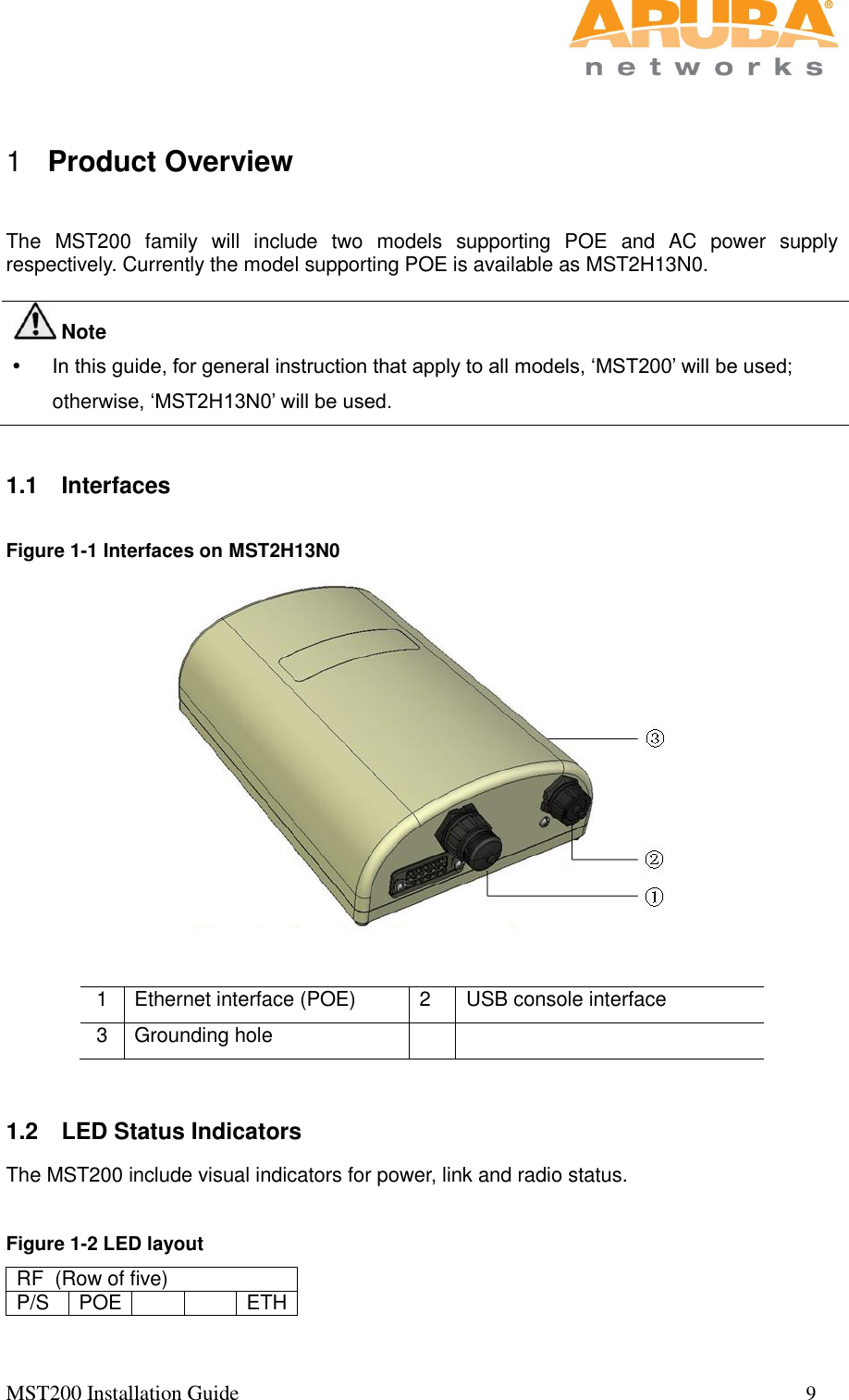
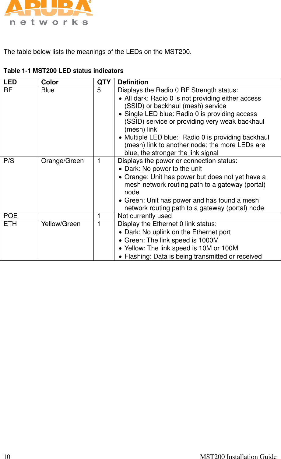
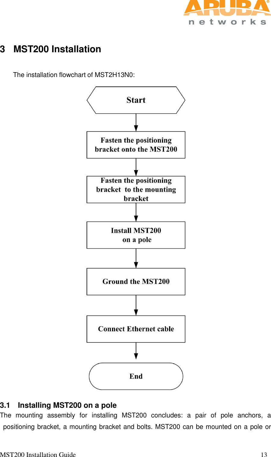
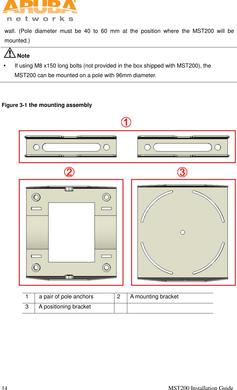
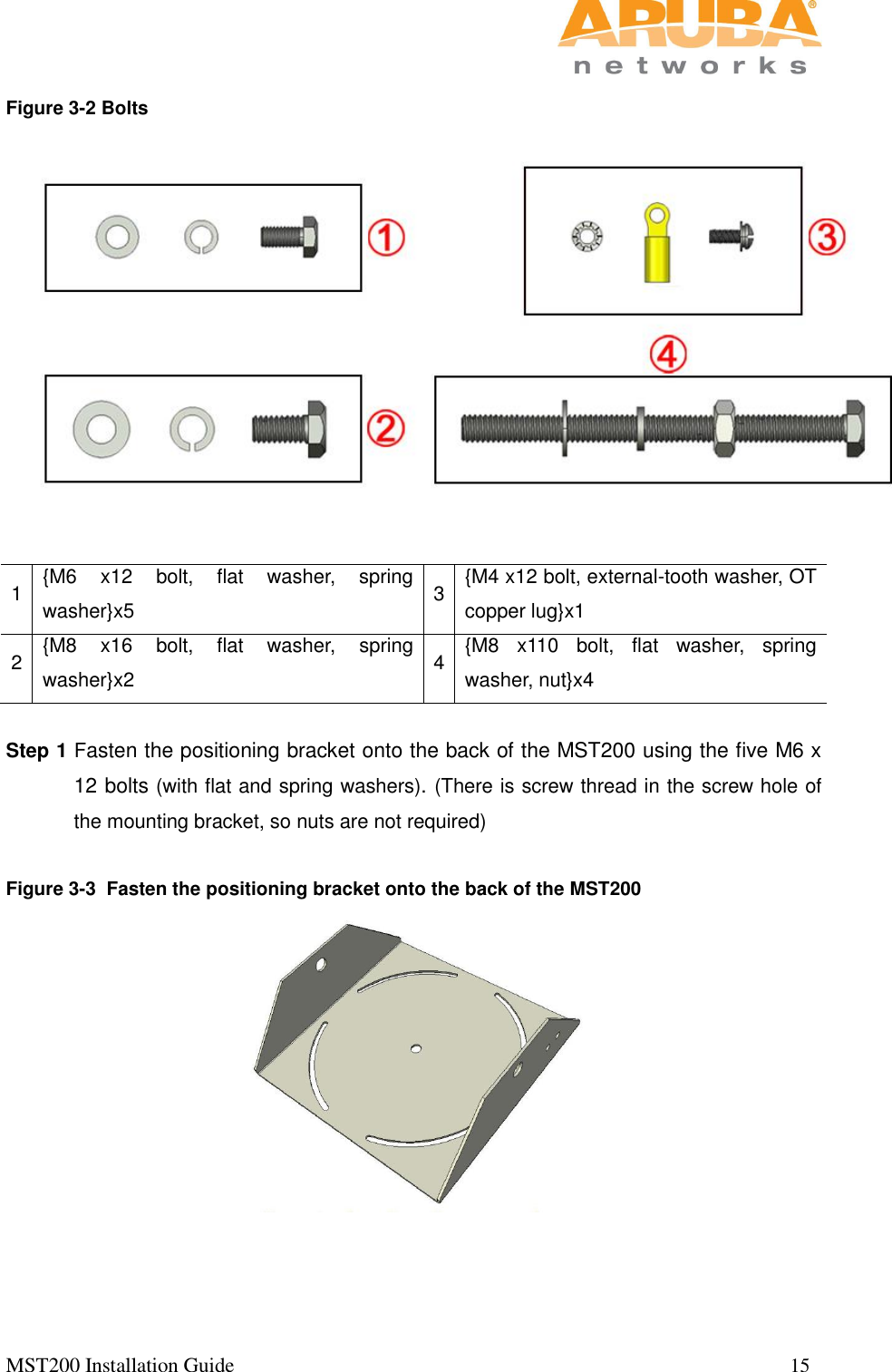
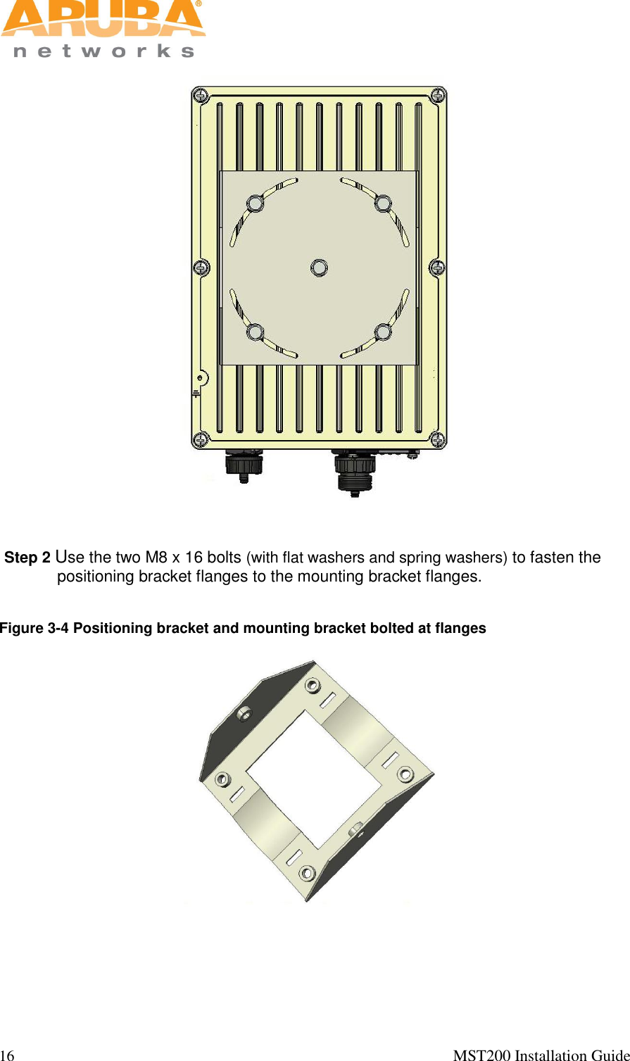
Installation Guide
2.
updated installation guide
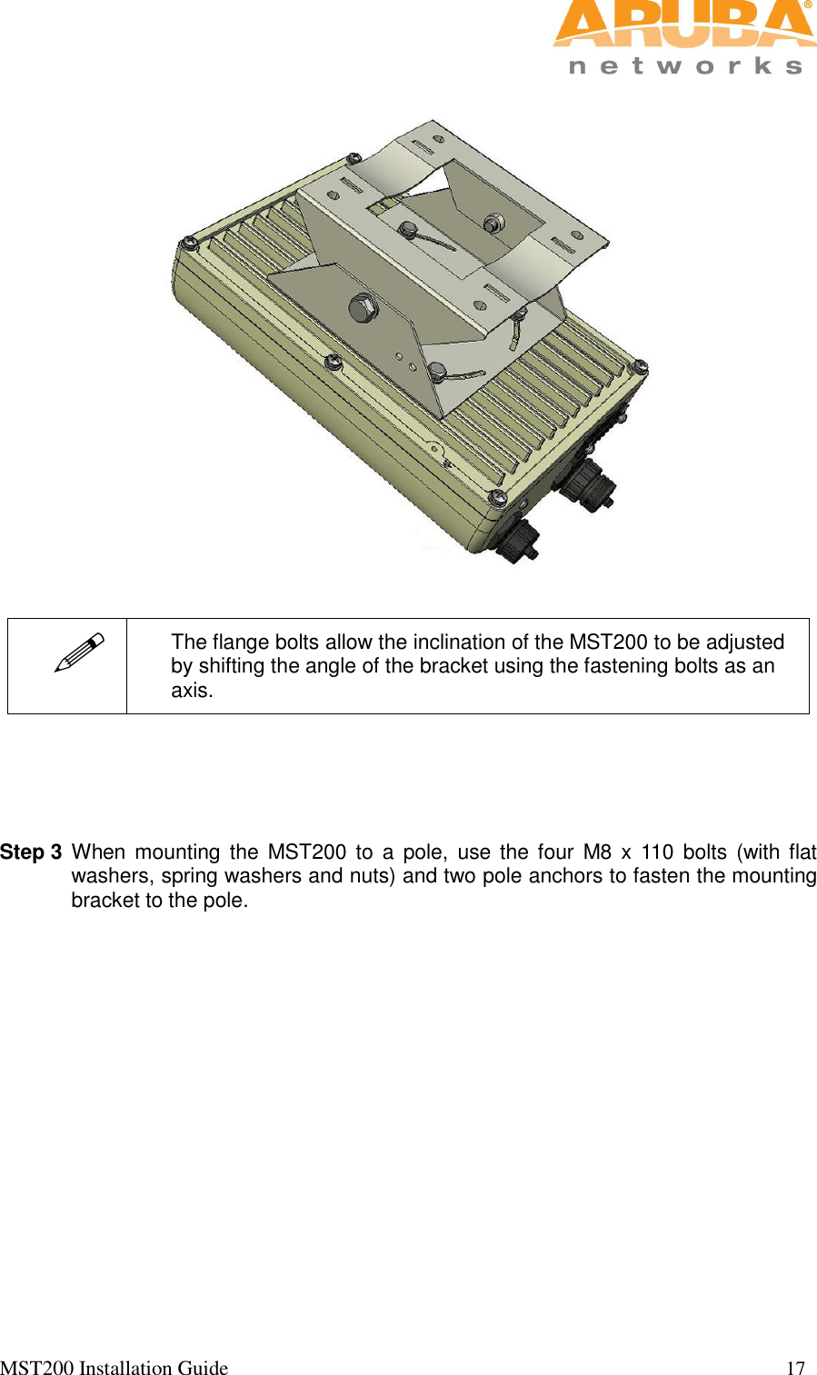
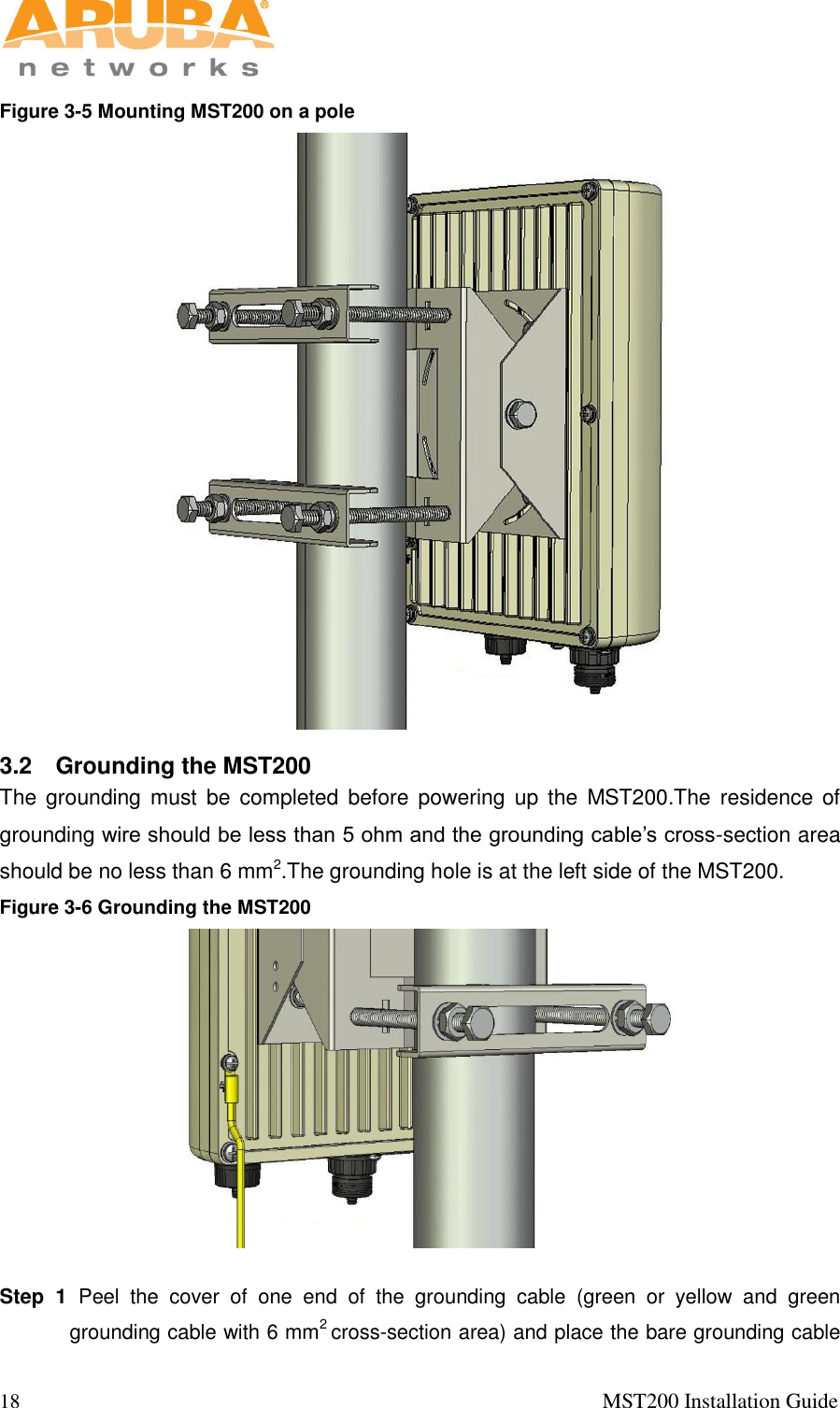
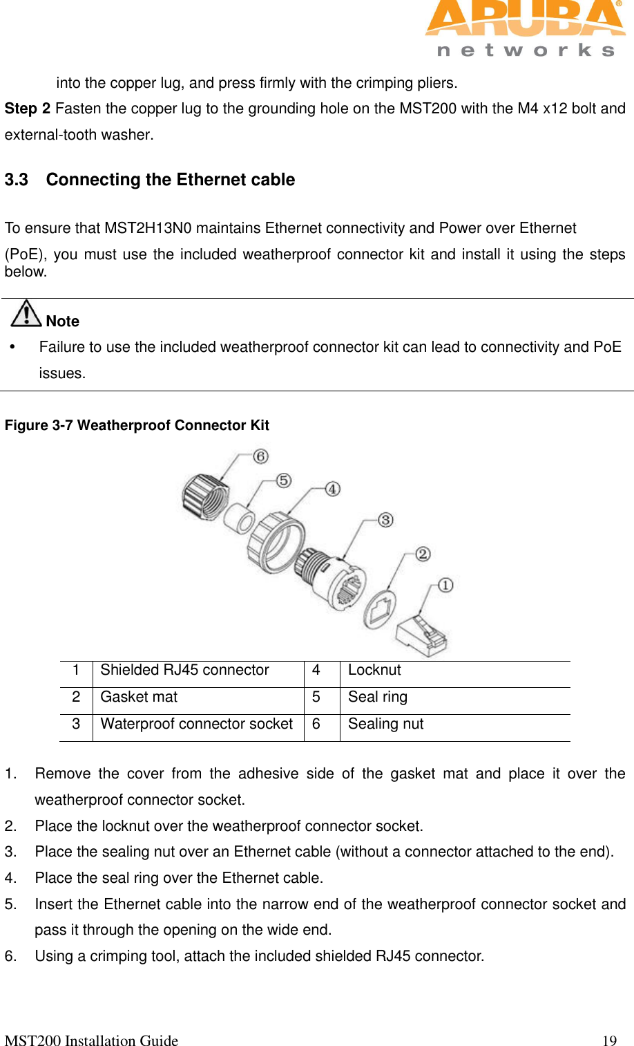
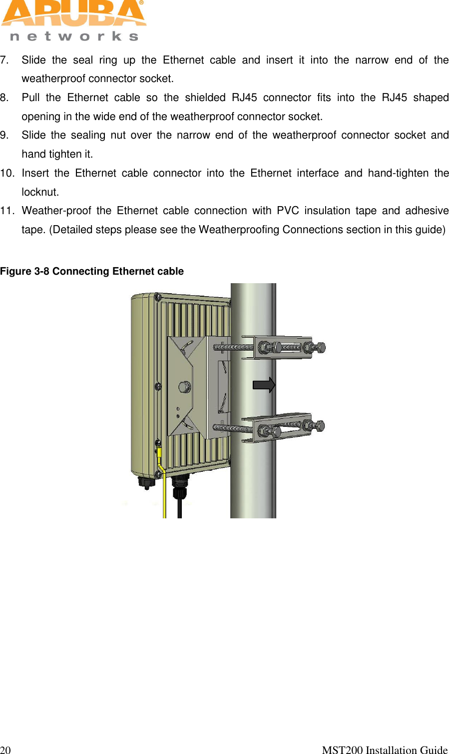
Installation Guide
Navigation menu
Upload a User Manual
Namespaces
Wiki Guide
HTML
PDF
Info
Views
User Manual
Discussion / Help
Navigation