Hewlett Packard Enterprise MST200DFS Wireless Mesh Access Router User Manual Aruba MST200 Installation Guide
Aruba Networks, Inc. Wireless Mesh Access Router Aruba MST200 Installation Guide
Contents
- 1. Installation Guide
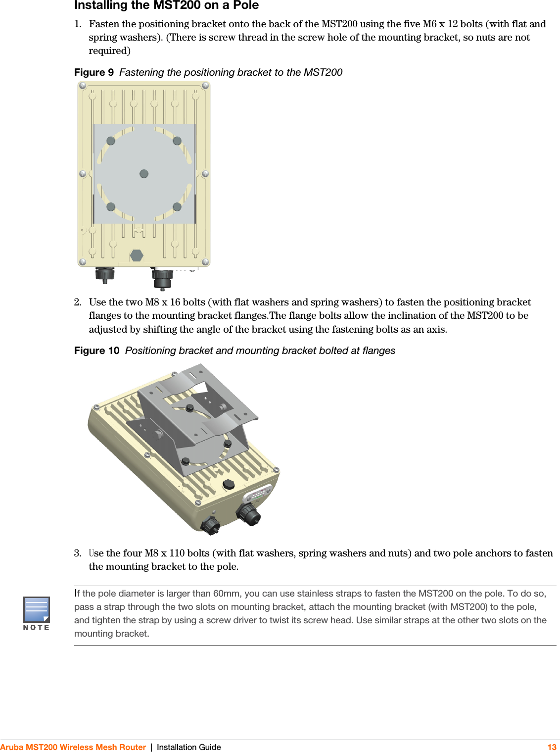
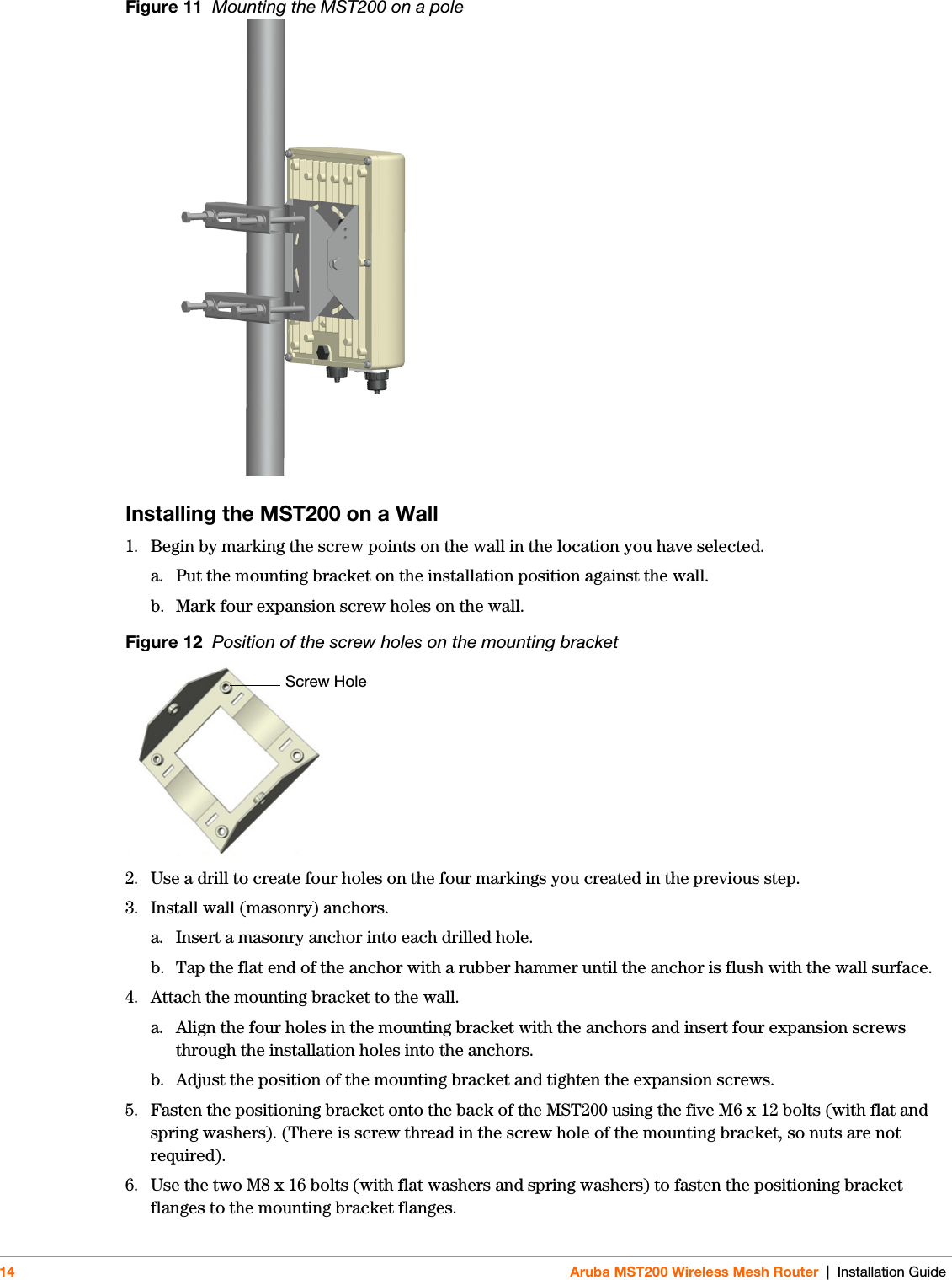
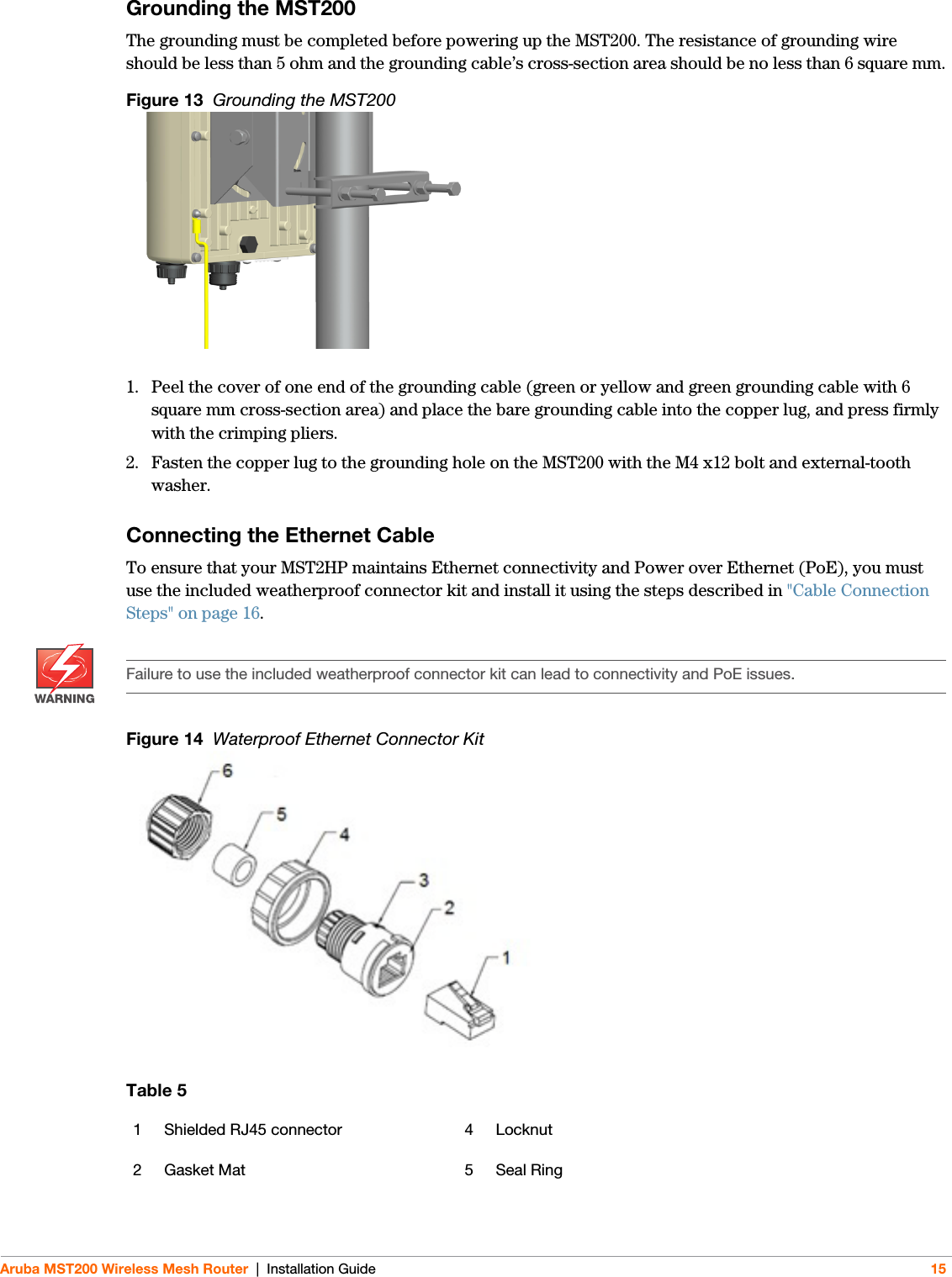
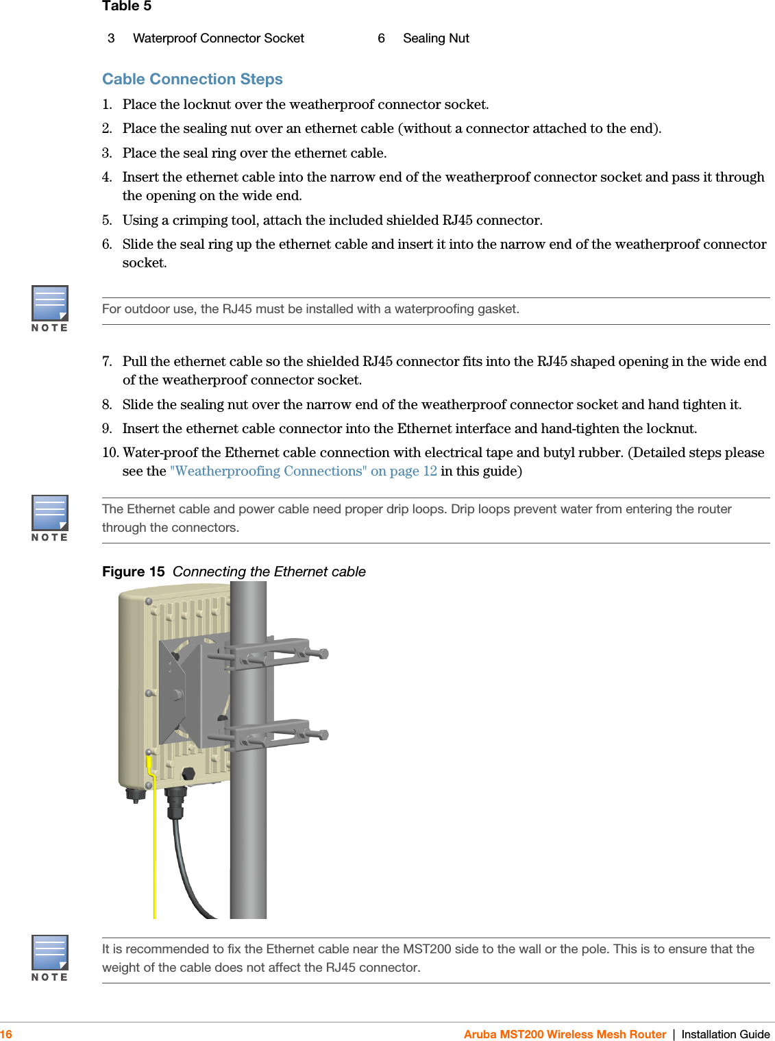
- 2. updated installation guide
updated installation guide