Hewlett Packard Enterprise MST200DFS Wireless Mesh Access Router User Manual Aruba MST200 Installation Guide
Aruba Networks, Inc. Wireless Mesh Access Router Aruba MST200 Installation Guide
Contents
- 1. Installation Guide
- 2. updated installation guide
updated installation guide
Aruba MST200 Wireless Mesh Router
Installation Guide
0511351-02 | July 2014 1
The Aruba AirMesh MST200 is a resilient, environmentally hardened, outdoor rated, single-radio IEEE
802.11 a/n wireless mesh access router. This router is part of Aruba’s comprehensive wireless network
solution.The MST200 delivers high-performance outdoor wireless mesh connectivity for remote locations
and devices such as IP video surveillance cameras, remote sensors, and digital signage. The MST200 is also
ideal for point-to-point outdoor mesh links between buildings and remote sites.
There are two versions of the MST200, which mainly differ in the way they receive power.
MST2HP: Power over Ethernet+ (PoE+) powered (802.3at)
MST2HAC: AC powered (100 - 240 VAC)
Guide Overview
"MST200 Hardware Overview" on page3 provides a detailed hardware overview of the two MST200
models.
"Outdoor Planning and Deployment Considerations" on page9 provides key questions to ask and items
to consider when deploying an outdoor wireless network.
"Weatherproofing Connections" on page12 provides instructions on weatherproofing the connectors on
the router.
"Installing the MST200" on page11 describes the multi-step process for a successful installation and
deployment of a MST200.
"Safety and Regulatory Compliance" on page21 provides an overview of safety and regulatory
compliance information.
MST200 Operations
Wireless mesh router for backhaul (IEEE 802.11 a/n)
MST2HP: IEEE 802.3at PoE+ compatible
MST2HAC: IEEE 802.3af Power Sourcing Equipment (PSE) device
MST200 requires the Aruba MeshOS operating system.
The MST2HAC can function as a Power Sourcing Equipment (PSE) device by providing power through its Ethernet
port in compliance with the IEEE 802.3af standard.
2Aruba MST200 Wireless Mesh Router | Installation Guide
Package Contents
Aruba MST200 AirMesh Router
MST200 Mounting Bracket
MST200 Positioning Bracket
Pole Anchors x 2
M6 x 12 bolts, flat washers, and spring washers x5
M8 x 16 bolts, flat washers, and spring washers x2
M4 x 12 bolt, external-tooth washer, and OT copper lug x1
M8 x 110 bolt, flat washers, spring washers, and nuts x4
RJ-45 Connector Kit
USB Console Cable
Installation Guide
Quick Start Guide
The MST200 does not ship with any power cables; these are available as accessories and should be ordered
separately.
Inform your supplier if there are any incorrect, missing, or damaged parts. If possible, retain the carton, including
the original packing materials. Use these materials to repack and return the unit to the supplier if needed.
Aruba MST200 Wireless Mesh Router | Installation Guide 3
MST200 Hardware Overview
The following section describes the hardware features of the MST2HP and MST2HAC.
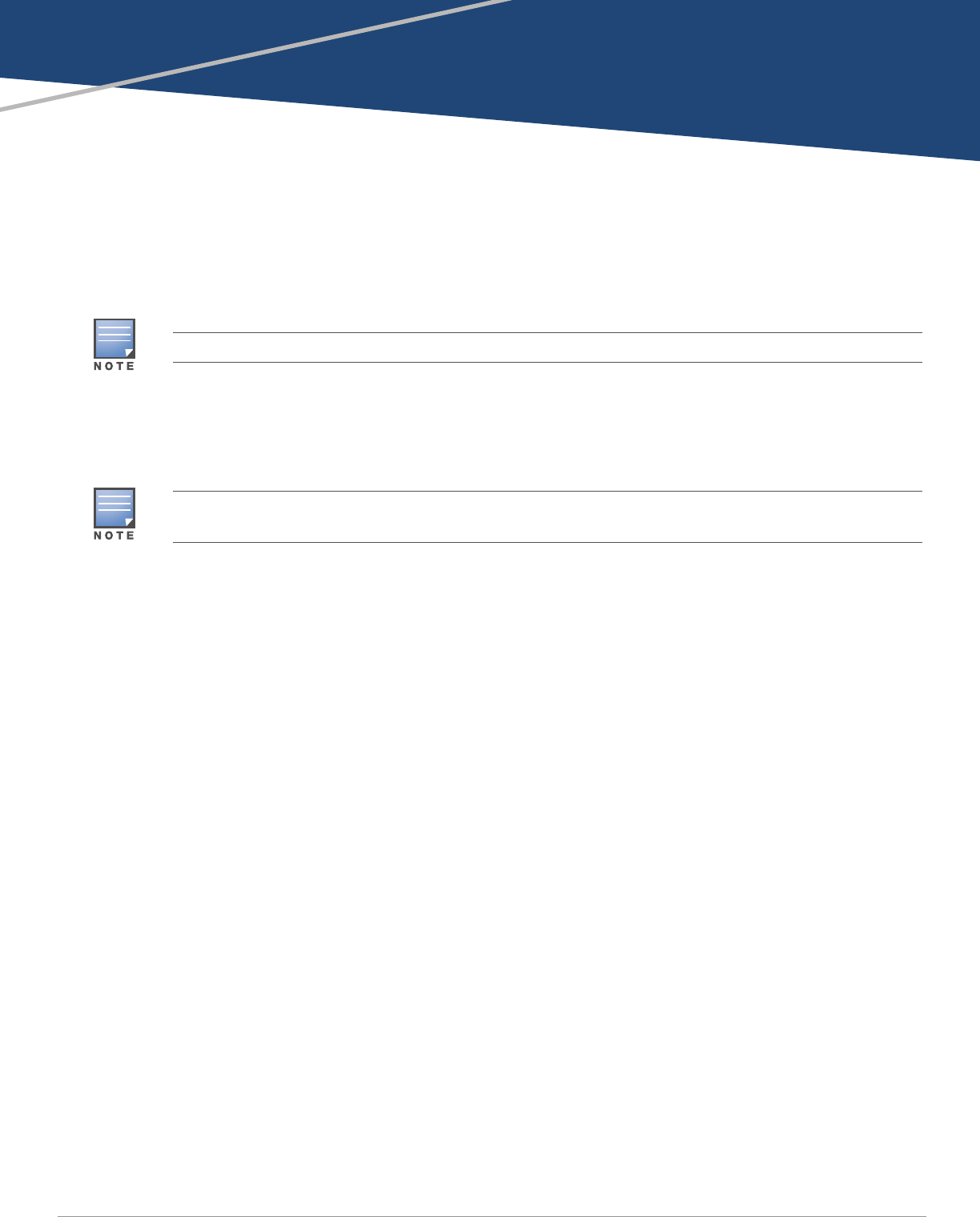
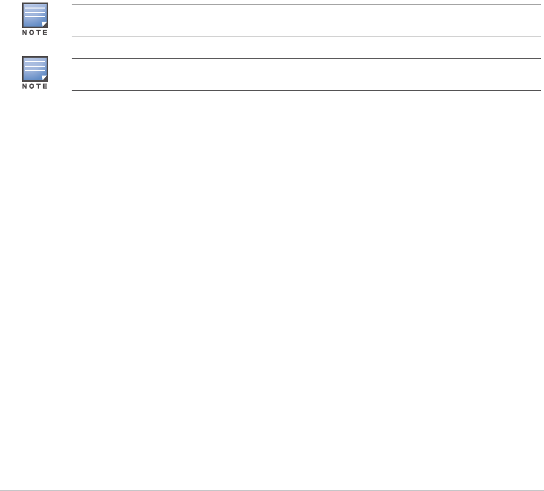
Figure 1 MST2HP overview
Ethernet Interface (PoE)
LED Status Indicators
USB Console Interface
Grounding Point Pressure Equalization Port
4Aruba MST200 Wireless Mesh Router | Installation Guide
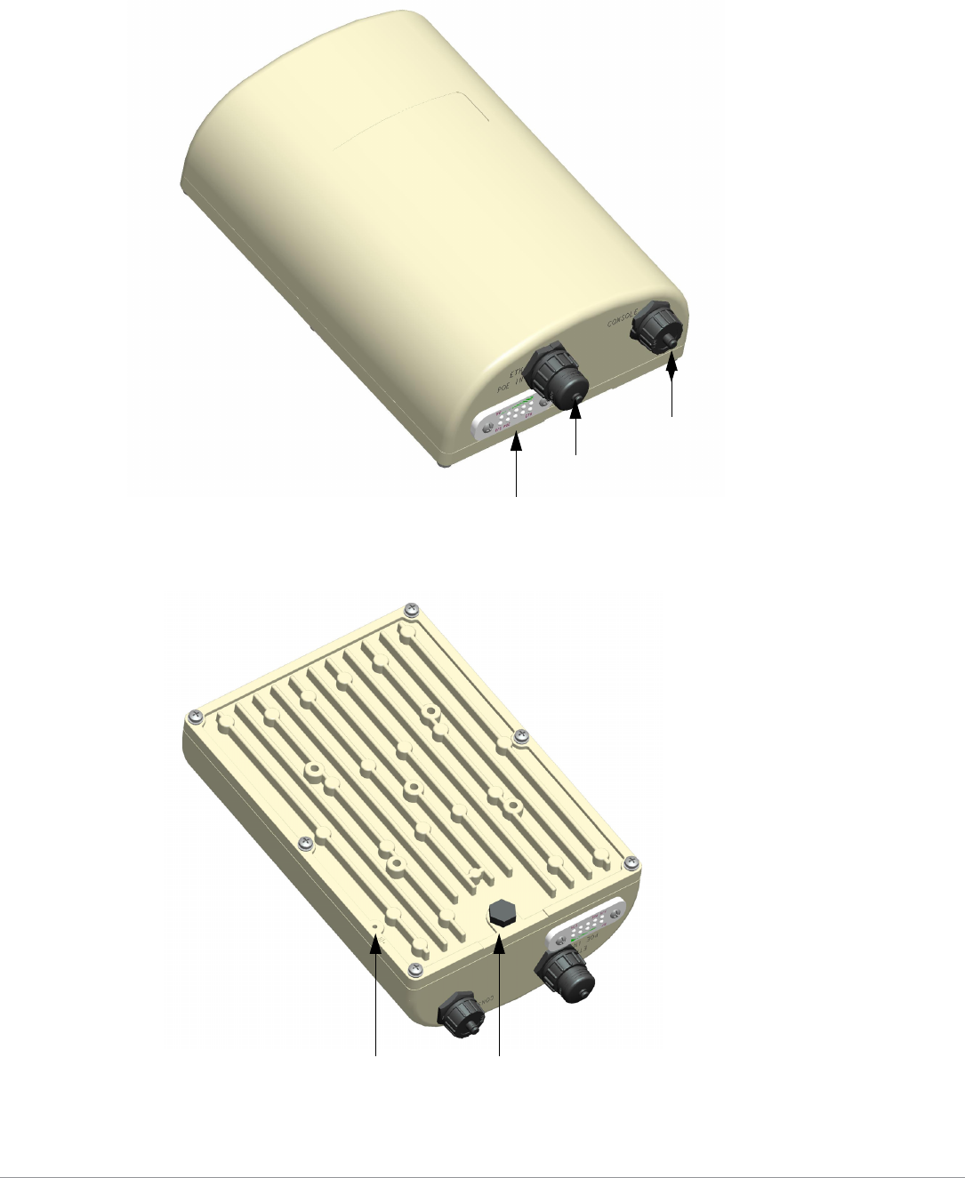
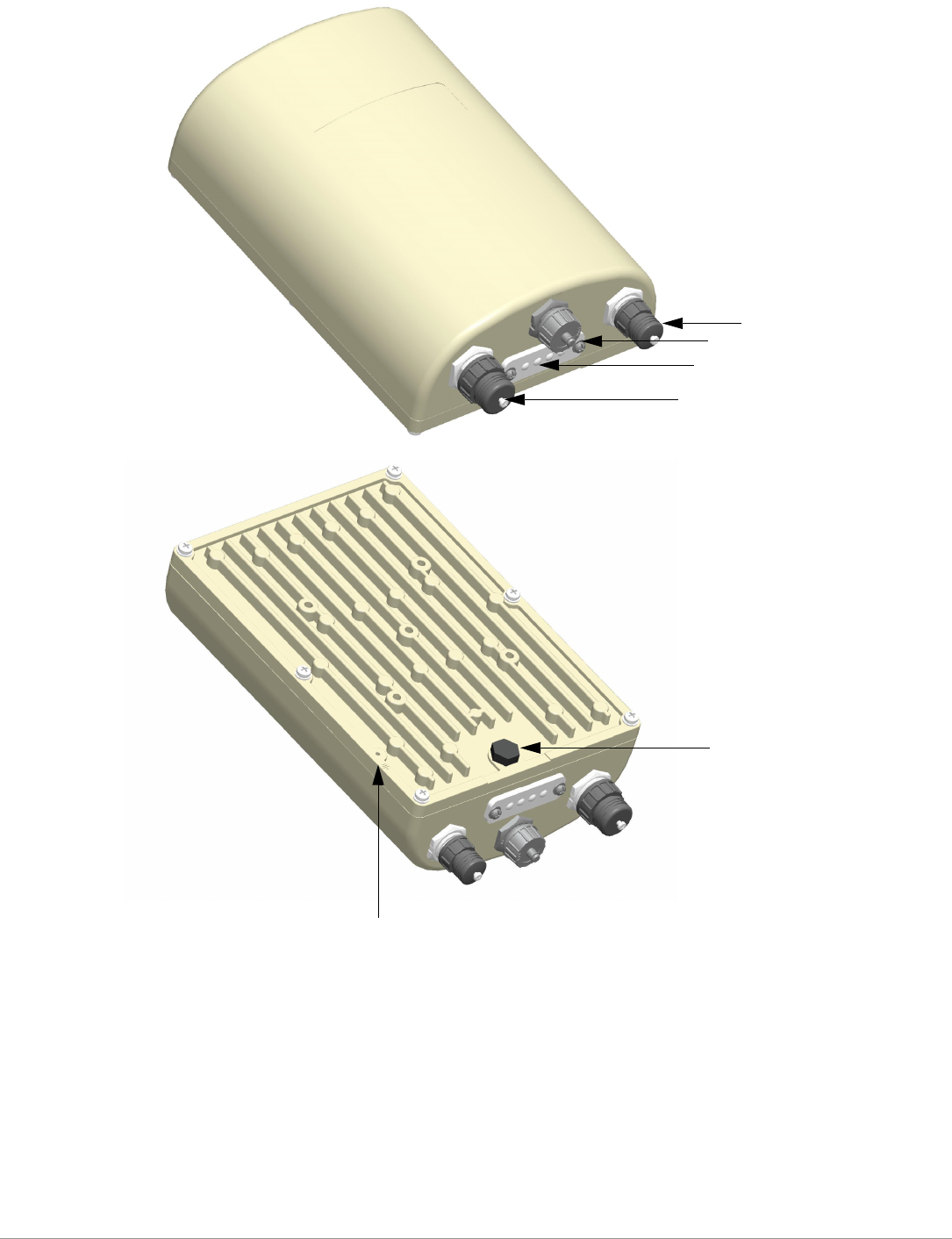
Figure 2 MST2HAC overview (protective caps removed)
Ethernet Interface (PoE Out)
USB Console Interface
LED Status Indicators
Power Interface
Pressure Equalization Port
Grounding Point

Aruba MST200 Wireless Mesh Router | Installation Guide 5
USB Console Interface
A USB serial console port is provided for connection to a terminal, allowing direct local management. Use
the included USB console cable to connect to the router. You can download the necessary driver for USB-
UART adapter from support.arubanetworks.com under the Tools & Resources tab.
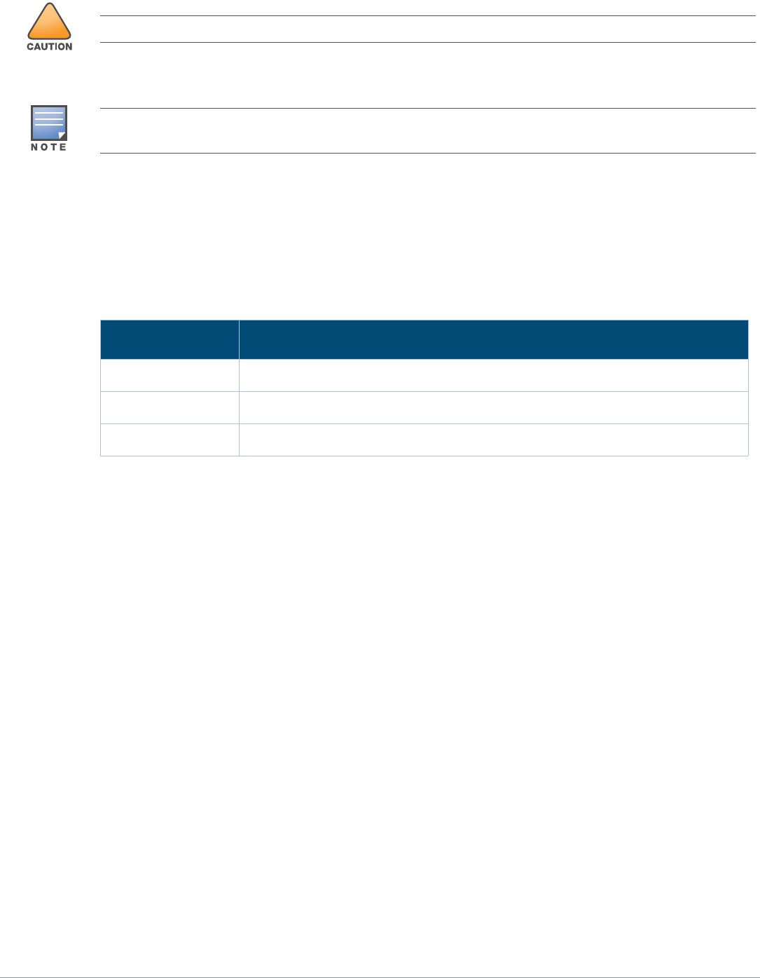
Use the following settings to access the terminal:
The baud rate setting depends on the manufacture date of the MST200 (before or after March 2012) and the
Serial Number (14 characters or 9 characters). The table above lists all the SKUs for MST200 along with the
corresponding baud rate.
Power Interface
The type of power interface on the MST200 depends on the model that you have purchased.
MST2HP: This version does not include a power interface since it is only powered by PoE+ (802.3at).
MST2HAC: One AC power connector.
Ethernet Interface
The MST200 is equipped with a 10/100/1000Base-T Gigabit Ethernet port for wired network connectivity. On
the MST2HP, this port also supports IEEE 802.3at Power over Ethernet (PoE), accepting 48 VDC as a
standards-defined powered device (PD) from a power sourcing equipment (PSE) device, such as a PoE
midspan injector. Inversely, the MST2HAC can act as a PSE device to provide IEEE802.3af PoE power to
devices such as a video camera, connected to the Ethernet port.
Table 1 Console Settings
Product SKUs Serial Number Baud Rate Data Bits Parity Stop Bits Flow
Control
MST2H13N0
MST2H13N0-JP
MST2H13N0-US
14 characters
(For example:
26A02110500467)
115200 8 None 1 None
MST2HP
MST2HP-JP
MST2HP-US
MST2HAC
MST2HAC-JP
MST2HAC-US
9 characters
(For example:
AZ1234567)
9600 8 None 1 None
6Aruba MST200 Wireless Mesh Router | Installation Guide
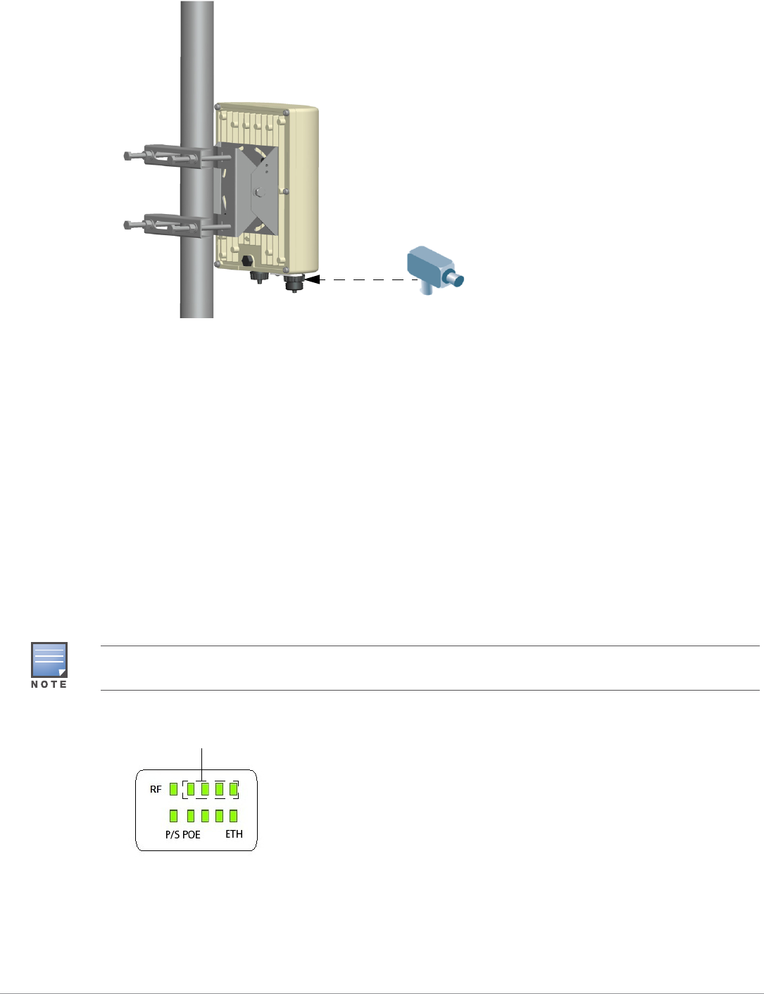
Figure 3 Connecting a Video Camera to the Ethernet Interface on MST2HAC
Pressure Equalization Port
The Pressure Equalization port allows air exchange between the MST200 and environment in a controlled
way that doesn’t allow water to get into the MST200. This balances the pressure and humidity inside and
outside the MST200.
Grounding Point
Always remember to protect your MST200 by installing grounding lines. The ground connection must be
completed before connecting power to the MST200 enclosure. Ensure that the resistance is less than 5 ohm
between the ground termination point and the grounding tier and the cross section of the grounding cable
should be no less than 6 square mm.
MST2HP LED Status Indicators
The MST2HP includes visual indicators for power, link, and radio status. Additionally, each radio has a four-
LED array that indicates received signal strength (RSSI).
Figure 4 MST2HP LED layout
The RSSI LED indicators represent varying degrees in the RSSI level. The absence of a signal is indicated by no
LED response. All four LEDs are active and lit is an indication of full signal strength.
RSSI for Radio 0

Aruba MST200 Wireless Mesh Router | Installation Guide 7
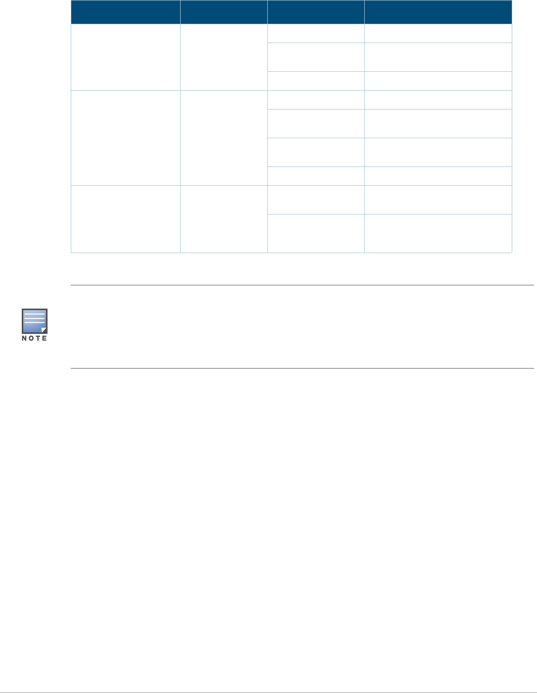
Table 2 lists the meanings of the LEDs on the MST2HP outdoor access point.
MST2HAC LED Status Indicators
The MST2HAC includes visual indicators for power, link, heat, and radio status.
Figure 5 MST2HAC LED layout
Table 3 lists the meanings of the LEDs on the MST2HAC outdoor access points.
Table 2 MST2HP LED Status Indicators
LED Function Indicator Status
P/S Router Power/
Ready Status
Off No power to the router
Orange Device booting, not ready
Green Device ready
POE N/A N/A Not currently used
ENT LAN/Network Link
Status
Off Ethernet link unavailable
On (Yellow) 10/100 Mbps Ethernet link
negotiated
On (Green) 1000 Mbps Ethernet link
negotiated
Blinking Traffic on Ethernet link
RF Radio 0 Status Off Radio 0 disabled
On (Blue) Radio 0 enabled
RSSI RSSI Level for
Radio 0
Off RSSI disabled/no signal
4 Step Progressive
Bars (Blue)
25/50/75/100%
Each bar represents a progressive
increase in signal strength, with 4
bars representing maximum signal
strength (100%).
Minimum data rate: One lit LEDs
Maximum data rate: Four lit LEDs
Table 3 MST2HAC LED Status Indicators
LED Function Indicator Status
P/S/H Router Power/
Ready Status/
Displays the
heating status of
low temperature
Off No power to the router
On (Red) Device alarm
On (Green) Device ready
Blinking Device booting, not ready
On (Blue) Device is pre-heating
8Aruba MST200 Wireless Mesh Router | Installation Guide
POE Displays PSE
power output
status
Off Device is not sourcing PoE power
On (Green) Device is sourcing PoE power to a
powered device in 802.3at mode
On (Amber) In 802.3at mode
ENT LAN/Network Link
Status
Off Ethernet link unavailable
On (Amber) 10/100 Mbps Ethernet link
negotiated
On (Green) 1000 Mbps Ethernet link
negotiated
Blinking Traffic on Ethernet link
RF 5GHz Radio Status Off No active BSS (for access) and
WDS neighbor with uptime < 5s
On (Amber) At least one active BSS (for
access) or at least one WDS
neighbor with uptime >= 5s
Table 3 MST2HAC LED Status Indicators (Continued)
LED Function Indicator Status
Starting with MeshOS 4.5, you can turn off the LEDs in the MST200 devices using the WMI and CLI. The LEDs are
enabled by default. This option may be used to disable the LED lights in a MST200 device that is mounted in an
elevated place on the city streets or residential areas, to avoid unwanted attention or disturbance. This feature turns
off only the LED lights that indicate the software status, for example the RF. The LEDs that indicate the hardware
status, for example Power, P/S, POE, and ETH, cannot be turned off using this feature. For additional details, refer
to the Aruba MeshOS User Guide and the Aruba MeshOS Command Reference Guide.

Aruba MST200 Wireless Mesh Router | Installation Guide 9
Outdoor Planning and Deployment Considerations
Prior to deploying an outdoor wireless network, the environment must be evaluated to plan for a successful
Aruba WLAN deployment. Successfully evaluating the environment enables the proper selection of Aruba
routers and antennas and assists in the determination of their placement for optimal RF coverage. This
process is considered WLAN or RF planning and Aruba’s system engineers can assist in the outdoor
planning process.
For WLAN systems being installed outdoors in the USA, the following requirements must be met.
1. Systems must be professionally installed by a qualified engineer familiar with WLAN, including Aruba
trained partners and resellers.
2. Operation in the 5600-5650-MHz band is prohibited.
3. When within 35 km distance of a TDWR, the center frequency of the WLAN must be separated from the
TDWR center frequency by 30 MHz.
a. If the radar is operating from 5600-5610 MHz, disable the use of channel 116 (5580 MHz).
b. If the radar is operating from 5630-5650 MHz, disable the use of channel 132 (5660 MHz).
For TWDR locations in the US please refer to www.wispa.org/tdwr-locations-and-frequencies.
Scale Requirements
The potentially immense scale of outdoor deployments requires consideration of factors that may not be as
important in a typical indoor deployment:
Range (distance): Range or distance between routers must be taken into account during the planning
phase. Available mounting locations are often far less flexible in an outdoor environment. Regardless of
these outdoor restrictions, the desired goal is to achieve results similar to an indoor deployment: a
“dense” RF deployment that supports advanced Aruba features, efficient client roaming, and failover.
Elevation: Proper consideration and planning for elevation differences between routers (router to
router) and router to Client can be critical to success. To plan for these differences in elevation, it is
important to understand the 3D coverage pattern provided by the antennas that will be deployed in the
environment.
Non-Fixed Considerations: The RF environment might change on a day to day basis. Keep non-fixed
items, such as shipping containers, vehicles, and future building construction, in mind when planning for
an outdoor deployment.
Identifying Known RF Scatterers/Reflectors/Interferences Sources
Identifying known RF scatterers/reflectors/interference sources while out in the field during the installation
phase is critical. Even though outdoor environments consist of fewer RF scatterers/reflectors/interference
sources compared to indoor environments, ensure that these sources are identified and taken into
consideration when installing and mounting a router to its fixed outdoor location.
RF Scatterers
Cement/Concrete
Natural Items: Trees/vegetation
Brick
RF Reflectors
Metal Objects: Roof-installed air-conditioning equipment, chain link fences (depending on aperture
size), other wire fences, or water pipes.
10 Aruba MST200 Wireless Mesh Router | Installation Guide
RF Interference Sources
Other 802.11a/b/g/n or broadband access equipment operating nearby
Industrial RF welding equipment or other Industrial, Scientific and Medical (ISM) equipment that utilizes
RF to heat or alter the physical properties of materials
Military, Commercial Aviation or Weather Radar Systems
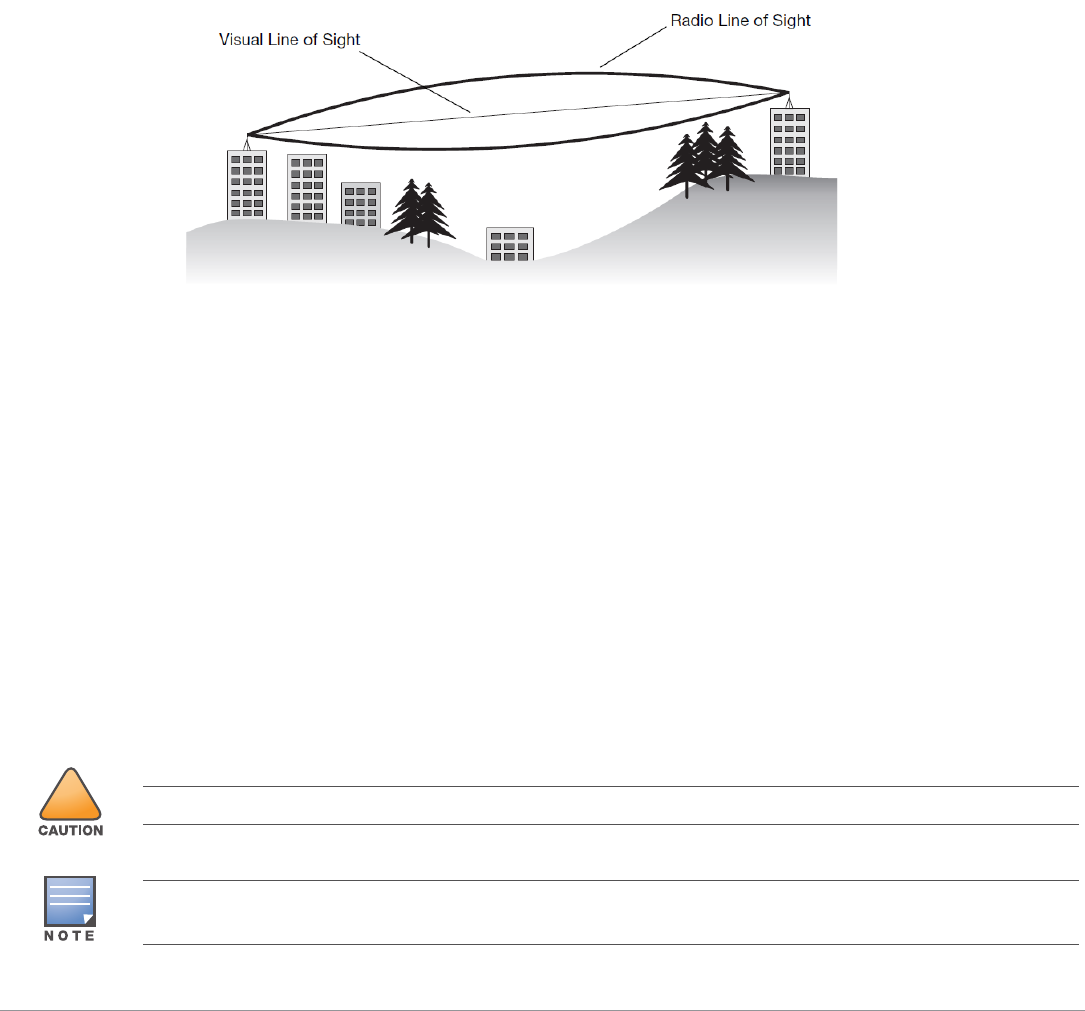
Line of Sight (Radio Path Planning)
A wireless bridge or mesh link requires a “radio line of sight” between the two antennas for optimum
performance. The concept of radio line of sight involves the area along a link through which the bulk of the
radio signal power travels. This area is known as the first Fresnel Zone of the radio link. For a radio link, no
object (including the ground) must intrude within 60% of the first Fresnel Zone.
Figure 6 illustrates the concept of a good radio line of sight.
Figure 6 Line of Sight
If there are obstacles in the radio path, there may still be a radio link but the quality and strength of the
signal will be affected. Calculating the maximum clearance from objects on a path is important as it directly
affects the decision on antenna placement and height. It is especially critical for long-distance links, where
the radio signal could easily be lost.
When planning the radio path for a wireless bridge or mesh link, consider these factors:
Avoid any partial line of sight between the antennas
Be cautious of trees or other foliage that may be near the path, or may grow and obstruct the path.
Be sure there is enough clearance from buildings and that no building construction may eventually block
the path.
For very long distance links, the curvature of the earth (20 cm per km) may need to be considered in the
calculation of relative heights.
Check the topology of the land between the antennas using topographical maps, aerial photos, or even
satellite image data (software packages are available that may include this information for your area)
Avoid a path that may incur temporary blockage due to the movement of cars, trains, or aircraft.
!
Never construct a radio mast, pole, or tower near overhead power lines.
Local regulations may limit or prevent construction of a high radio mast or tower. If your wireless bridge or mesh link
requires a high radio mast or tower, consult a professional contractor for advice.

Aruba MST200 Wireless Mesh Router | Installation Guide 11
Radio Interference
The avoidance of radio interference is an important part of wireless link planning. Interference is caused by
other radio transmissions using the same or an adjacent channel frequency. You should first scan your
proposed site using a spectrum analyzer to determine if there are any strong radio signals using the 802.11a/
b/g channel frequencies. Always use a channel frequency that is furthest away from another signal.
If radio interference is still a problem with your wireless bridge or mesh link, changing the antenna
direction may improve the situation.
Weather Conditions
When planning wireless bridge or mesh links, you must take into account any extreme weather conditions
that are known to affect your location. Consider these factors:
Temperature: The wireless bridge or mesh link is tested for normal operation in temperatures from -30ºC
to 55ºC. Operating in temperatures outside of this range may cause the unit to fail.
Wind Velocity: The wireless bridge or mesh link can operate in winds up to 165 miles per hour. You must
consider the known maximum wind velocity and direction at the site and be sure that any supporting
structure, such as a pole, mast, or tower, is built to withstand this force.
Rain: The wireless bridge or mesh link is weatherproofed against rain. However, it is recommended to
apply weatherproof sealing tape around the Ethernet port and antenna connectors for extra protection.
If moisture enters a connector, it may cause a degradation in performance or even a complete failure of
the link.
Snow and Ice: Falling snow, like rain, has no significant effect on the radio signal. However, a buildup of
snow or ice on antennas may cause the link to fail. In this case, the snow or ice has to be cleared from
the antennas to restore operation of the link.
Ethernet Cabling
When a suitable location has been determined for the router, you must plan a cable route from the wireless
bridge or mesh link outdoors to a suitable power and/or network source.
Consider these points:
The Ethernet cable length should never be longer than 90 m (295 ft).
Determine a building entry point for the cable (if applicable).
Determine if conduits, bracing, or other structures are required for safety or protection of the cable.
For lightning protection at the power injector end of the cable, consider using a lightning arrestor
immediately before the cable enters the building
Grounding
It is important that the wireless bridge or mesh link, cables, and any supporting structures are properly
grounded. Each MST200 router includes a grounding screw for attaching a ground wire. Be sure that
grounding is available and that it meets local and national electrical codes. Ground the access point first
using the external ground stud on the unit before making any other connection.
Installing the MST200
12 Aruba MST200 Wireless Mesh Router | Installation Guide
The MST200 can be installed on a wall or attached to a pole. (Pole diameter must be 40 to 60 mm at the
position where the MST200 will be mounted.) The following section describes how to attach the necessary
hardware to the router and how to mount the router in the selected location.
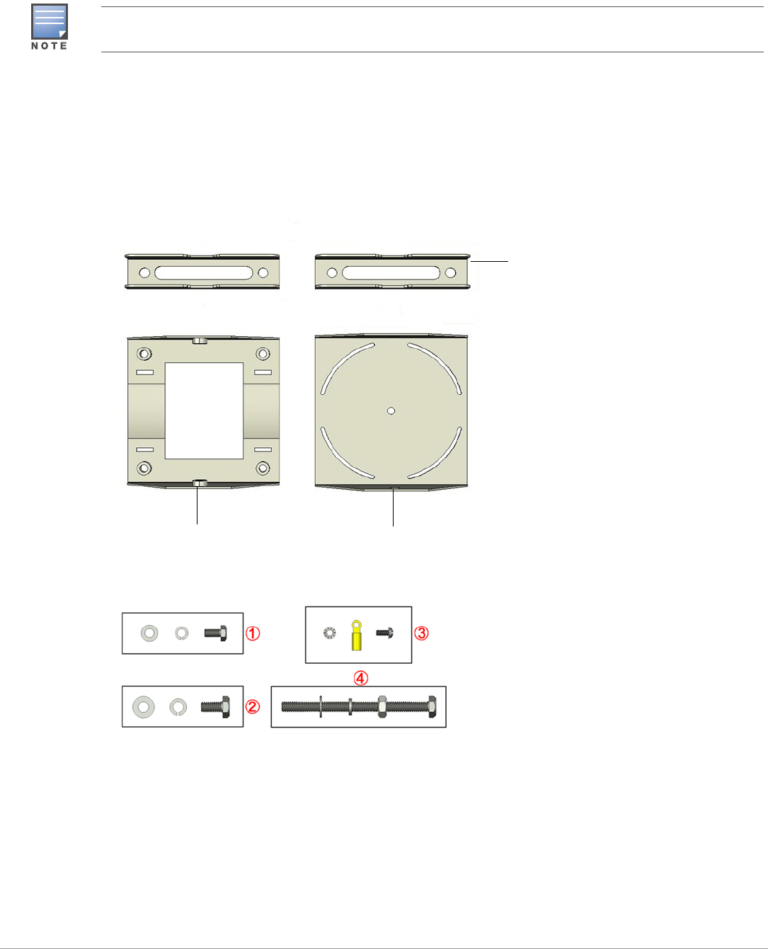
The mounting assembly for installing MST200 includes the following as shown in Figure 7:
Pole anchors x 2
Positioning bracket
Mounting bracket
Bolts.
Figure 7 The mounting assembly
Figure 8 Bolts
You can mount the MST200 on a pole with 96mm diameter using M8 x150 long bolts (not provided in the box
shipped with MST200).
Table 4
1 {M6 x12 bolt, flat washer, spring washer}x5 3 {M4 x12 bolt, external-tooth washer, OT copper lug}x1
2 {M8 x16 bolt, flat washer, spring washer}x2 4 {M8 x110 bolt, flat washer, spring washer, nut}x4
Pole Anchor
Mounting Bracket Positioning Bracket
Aruba MST200 Wireless Mesh Router | Installation Guide 13
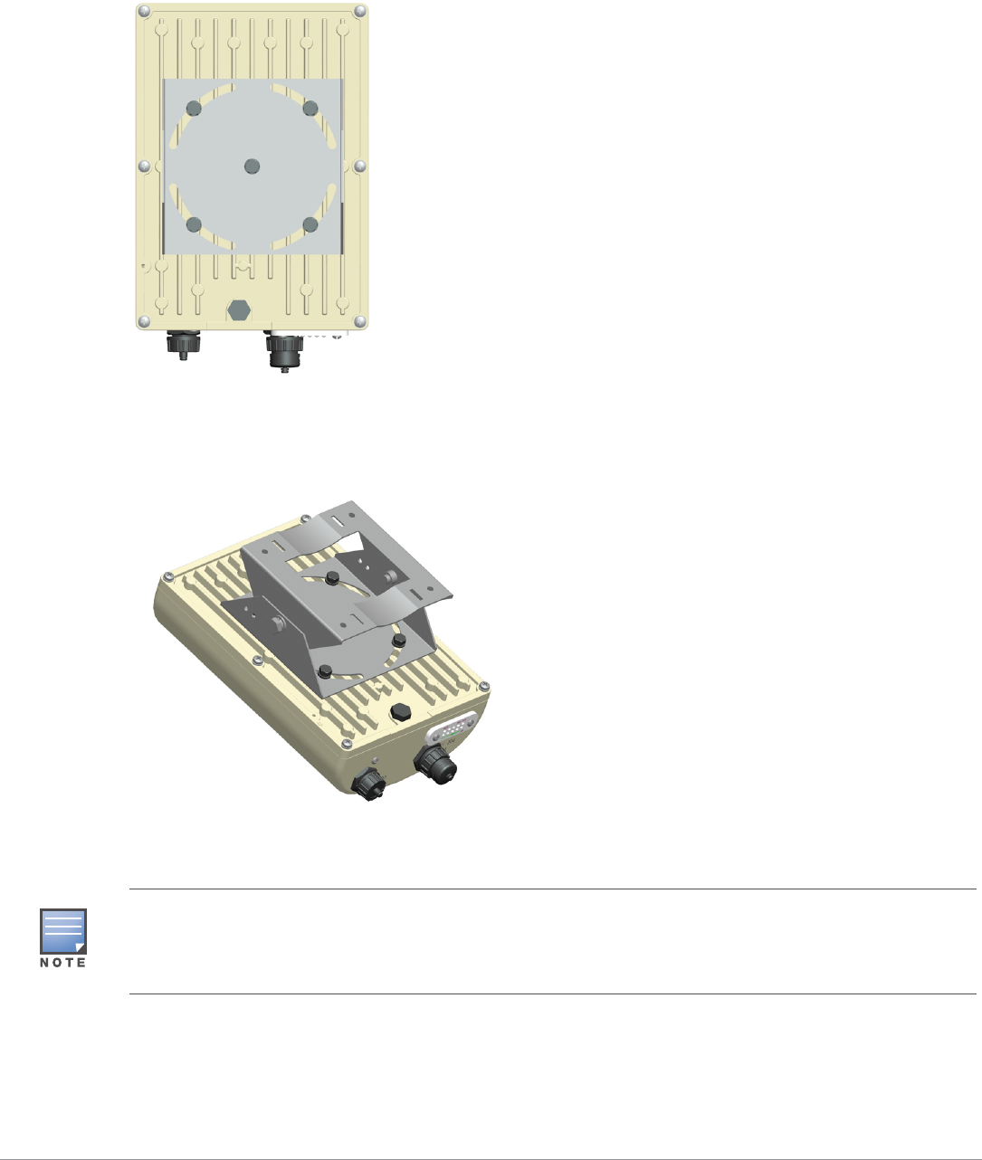
Installing the MST200 on a Pole
1. Fasten the positioning bracket onto the back of the MST200 using the five M6 x 12 bolts (with flat and
spring washers). (There is screw thread in the screw hole of the mounting bracket, so nuts are not
required)
Figure 9 Fastening the positioning bracket to the MST200
2. Use the two M8 x 16 bolts (with flat washers and spring washers) to fasten the positioning bracket
flanges to the mounting bracket flanges.The flange bolts allow the inclination of the MST200 to be
adjusted by shifting the angle of the bracket using the fastening bolts as an axis.
Figure 10 Positioning bracket and mounting bracket bolted at flanges
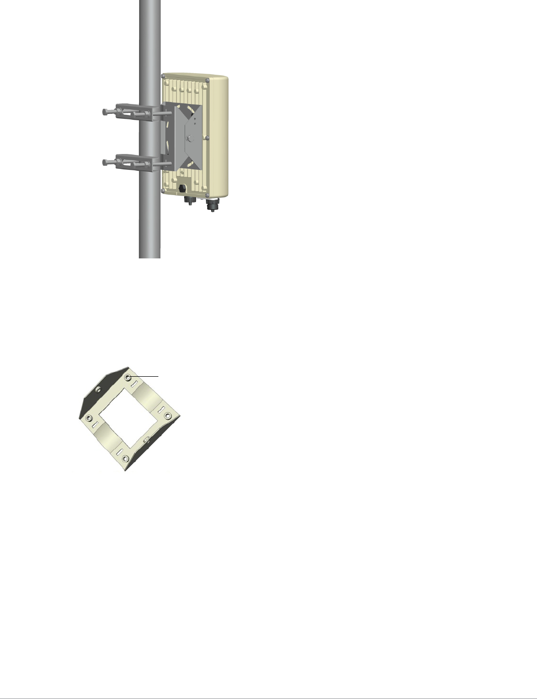
3. Use the four M8 x 110 bolts (with flat washers, spring washers and nuts) and two pole anchors to fasten
the mounting bracket to the pole.
If the pole diameter is larger than 60mm, you can use stainless straps to fasten the MST200 on the pole. To do so,
pass a strap through the two slots on mounting bracket, attach the mounting bracket (with MST200) to the pole,
and tighten the strap by using a screw driver to twist its screw head. Use similar straps at the other two slots on the
mounting bracket.
14 Aruba MST200 Wireless Mesh Router | Installation Guide
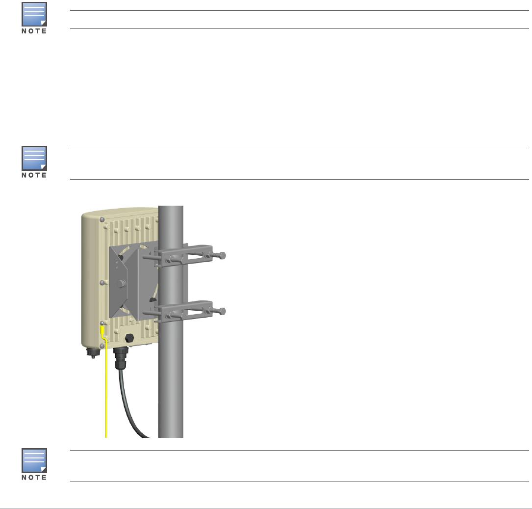
Figure 11 Mounting the MST200 on a pole
Installing the MST200 on a Wall
1. Begin by marking the screw points on the wall in the location you have selected.
a. Put the mounting bracket on the installation position against the wall.
b. Mark four expansion screw holes on the wall.
Figure 12 Position of the screw holes on the mounting bracket
2. Use a drill to create four holes on the four markings you created in the previous step.
3. Install wall (masonry) anchors.
a. Insert a masonry anchor into each drilled hole.
b. Tap the flat end of the anchor with a rubber hammer until the anchor is flush with the wall surface.
4. Attach the mounting bracket to the wall.
a. Align the four holes in the mounting bracket with the anchors and insert four expansion screws
through the installation holes into the anchors.
b. Adjust the position of the mounting bracket and tighten the expansion screws.
5. Fasten the positioning bracket onto the back of the MST200 using the five M6 x 12 bolts (with flat and
spring washers). (There is screw thread in the screw hole of the mounting bracket, so nuts are not
required).
6. Use the two M8 x 16 bolts (with flat washers and spring washers) to fasten the positioning bracket
flanges to the mounting bracket flanges.
Screw Hole
Aruba MST200 Wireless Mesh Router | Installation Guide 15
Grounding the MST200
The grounding must be completed before powering up the MST200. The resistance of grounding wire
should be less than 5 ohm and the grounding cable’s cross-section area should be no less than 6 square mm.
Figure 13 Grounding the MST200
1. Peel the cover of one end of the grounding cable (green or yellow and green grounding cable with 6
square mm cross-section area) and place the bare grounding cable into the copper lug, and press firmly
with the crimping pliers.
2. Fasten the copper lug to the grounding hole on the MST200 with the M4 x12 bolt and external-tooth
washer.
Connecting the Ethernet Cable
To ensure that your MST2HP maintains Ethernet connectivity and Power over Ethernet (PoE), you must
use the included weatherproof connector kit and install it using the steps described in "Cable Connection
Steps" on page16.
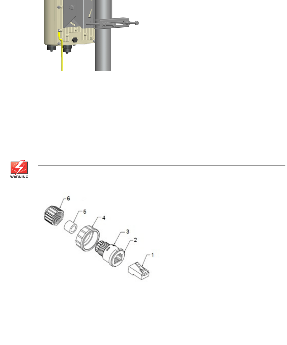
Figure 14 Waterproof Ethernet Connector Kit
Failure to use the included weatherproof connector kit can lead to connectivity and PoE issues.
Table 5
1 Shielded RJ45 connector 4 Locknut
2Gasket Mat 5Seal Ring
16 Aruba MST200 Wireless Mesh Router | Installation Guide
Cable Connection Steps
1. Place the locknut over the weatherproof connector socket.
2. Place the sealing nut over an ethernet cable (without a connector attached to the end).
3. Place the seal ring over the ethernet cable.
4. Insert the ethernet cable into the narrow end of the weatherproof connector socket and pass it through
the opening on the wide end.
5. Using a crimping tool, attach the included shielded RJ45 connector.
6. Slide the seal ring up the ethernet cable and insert it into the narrow end of the weatherproof connector
socket.
7. Pull the ethernet cable so the shielded RJ45 connector fits into the RJ45 shaped opening in the wide end
of the weatherproof connector socket.
8. Slide the sealing nut over the narrow end of the weatherproof connector socket and hand tighten it.
9. Insert the ethernet cable connector into the Ethernet interface and hand-tighten the locknut.
10. Water-proof the Ethernet cable connection with electrical tape and butyl rubber. (Detailed steps please
see the "Weatherproofing Connections" on page12 in this guide)
Figure 15 Connecting the Ethernet cable
3 Waterproof Connector Socket 6 Sealing Nut
Table 5
For outdoor use, the RJ45 must be installed with a waterproofing gasket.
The Ethernet cable and power cable need proper drip loops. Drip loops prevent water from entering the router
through the connectors.
It is recommended to fix the Ethernet cable near the MST200 side to the wall or the pole. This is to ensure that the
weight of the cable does not affect the RJ45 connector.
Aruba MST200 Wireless Mesh Router | Installation Guide 17
Connecting the Power Cable (MST2HAC)
The MST2HAC versions need an outdoor rated power cable to connect to a compatible AC power source.
AC power source specifications (at MST200 interface): 100-240Vac, 100W
The MST2HAC product offering offers two ways to connect the unit to AC power. Two power cord variants
are offered and a connector kit that allows the customer to assemble their own cable if the standard
offering does not meet deployment needs.
The applicable SKUs for these options are:
The difference between the NA and INTL part variants is the color coding of the conductors.
The North American cable uses Black (Hot), White (Neutral), and Green (Ground).
The INTL part follows the international schema of Brown (Hot), Blue (Neutral) and Yellow/Green
(Ground)
Best Practice for Outdoor Connection to AC Mains
In all circumstances and with any outdoor infrastructure the recommended practice is to connect to AC
mains in an order grade weather protected junction box. This needs to be implemented by a qualified
resource in a manner that is consistent with the electrical code in force in the jurisdiction of deployment. In
many countries this will require a licensed electrician to perform this operation.
In Japan, this would is a Certified Electrician by Ministry of Economy, Trade and Industry.
The use of plugs with infrastructure equipment is suitable only for temporary installs where nuisance
tripping of GFI plugs is considered tolerable. Should it be desired to attach a plug to the cable assemblies
then the installer is expected to follow all directions provided with the plug end in a fashion consistent with
local electrical code.
Use of the CKIT-OD-AC-P
Assembly instructions for this part are shipped with the part. All instructions must be followed to ensure
proper assembly of the connector onto the cable.
The required specifications for third party cable used with the CKIT solution are as follows:
AC power cable specifications (when using AC connector kit and custom cable): minimum voltage/
current rating 250V/1A, diameter 6-12mm, rated for outdoor use and UV exposure
!
Installation and service of Aruba Networks products should be performed by Professional Installers.
The MST200 does not ship with any power cables; these are available as accessories and should be ordered
separately.
Table 6 SKUs for Powering Options
Part Number Description
PC-OD-AC-P-NA Weatherproof AC power cable(5m), North America version
PC-OD-AC-P-INT Weatherproof AC power cable(5m), International (EU) version
CKIT-OD-AC-P Weatherproof connector kit for AC power interface

18 Aruba MST200 Wireless Mesh Router | Installation Guide
AC Power Cable Connector PIN OUT
Figure 16 AC power cable connector
Connecting the Power Cable to the MST2HAC
1. Remove the protective cap on the power interface.
2. Insert the power cable connector into the power interface and hand-fasten the locknut.
3. Water-proof the power cable connection with PVC insulation tape, adhesive insulation tape and strap.
HotNeutral
Ground

Aruba MST200 Wireless Mesh Router | Installation Guide 19
Product Specifications
Mechanical
Dimensions (H x W x D)
10 inches x 7 inches x 3.3 inches
255mm x 180mm x 82mm
Weight: 5.18 lbs/2.35 kg
Shipping Dimensions (H x W x D)
16.7 inches x 13.2 inches x 8.8 inches
425 mm x 335 mm x 225 mm
Shipping Weight: 9.99 lbs/4.53 kg
Temperature
Operating (MST2HP): -30ºC to 60ºC (-22ºF to 140ºF)
Operating (MST2HAC): -40ºC to 55ºC (-40ºF to 131ºF)
Storage: –40ºC to 70ºC (-40ºF to 158ºF)
Relative Humidity: 5% to 95% non-condensing
Mounting: wall or pole mountable
Antennas:
Built-in antenna
Frequency range and max gain:
5.500 to 5.550 GHz: 11.5dBi
5.550 to 5.875 GHz: 13dBi
Beamwidth:
E-plane: 13 degrees
H-plane: 55 degrees
Visual Status Indicators (LEDs): See Table 2 and Table 3
Electrical
Power In
MST2HP: 48-volt DC 802.3at power over Ethernet (PoE+)
MST2HAC: 100-240 volt AC from external AC power source
Maximum power consumption: 12.5 watts (excludes power consumed by any PoE device connected to
and powered by the MST2HAC)
Power Out
The AC powered models provide an 802.3af PoE power source (PSE) on the Ethernet interface.
Interfaces
Network:
1 x 10/100/1000BASE-T Ethernet (RJ-45), auto-sensing link speed and MDI/MDX
Power:
1 x AC power connector (in MST2HAC model only)

20 Aruba MST200 Wireless Mesh Router | Installation Guide
Other:
1 x USB console interface
Wireless LAN
Router type: single-radio, 802.11a/n 5GHz outdoor
Supported frequency bands (country-specific restrictions apply):
5.500 to 5.550 GHz
5.550 to 5.875 GHz
Available channels: Controller-managed, dependent upon configured regulatory domain
Supported radio technologies:
802.11a/n: Orthogonal frequency division multiplexing (OFDM)
802.11n: 2x2 MIMO with two spatial streams
Supported modulation types:
802.11a/n: BPSK, QPSK, 16-QAM, 64-QAM
Maximum transmit power: 25 dBm (325 mW) (limited by local regulatory requirements)
Maximum ratio combining (MRC) for improved receiver performance
Association rates (Mbps):
802.11a: 6, 9, 12, 18, 24, 36, 48, 54
802.11n: MCS0 - MCS15 (6.5 Mbps to 300 Mbps)
802.11n high-throughput (HT) support: HT 20/40
802.11n packet aggregation: A-MPDU, A-MSDU
Aruba MST200 Wireless Mesh Router | Installation Guide 21
Safety and Regulatory Compliance
Aruba Networks provides a multi-language document that contains country-specific restrictions and
additional safety and regulatory information for all Aruba access points. This document can be viewed or
downloaded from the following location: www.arubanetworks.com/safety_addendum
FCC Class B Device
This equipment has been tested and found to comply with the limits for a Class B digital device, pursuant to
part 15 of the FCC Rules. These limits are designed to provide reasonable protection against harmful
interference in a residential installation. This equipment generates, uses and can radiate radio frequency
energy and, if not installed and used in accordance with the instructions, may cause harmful interference to
radio communications. However, there is no guarantee that interference will not occur in a particular
installation. If this equipment does cause harmful interference to radio or television reception, which can be
determined by turning the equipment off and on, the user is encouraged to try to correct the interference by
one or more of the following measures:
Reorient or relocate the receiving antenna.
Increase the separation between the equipment and receiver.
Connect the equipment into an outlet on a circuit different from that to which the receiver is connected.
Consult the dealer or an experienced radio/ TV technician for help.
For a complete list of Country Specific Regulations please speak with your Aruba Representative.
Taiwan NCC
!
RF Radiation Exposure Statement: This equipment complies with FCC RF radiation exposure limits. This
equipment should be installed and operated with a minimum distance of 13.78 inches (35 cm) between the radiator
and your body for 2.4 GHz and 5 GHz operations. This transmitter must not be co-located or operating in
conjunction with any other antenna or transmitter. When operated in the 5.15 to 5.25 GHz frequency range, this
device is restricted to indoor use to reduce the potential for harmful interference with co-channel Mobile Satellite
Systems.
!
Aruba AirMesh routers and the AP-LAR-1 lightning arrestor are required to be installed by a professional installer.
The professional installer is responsible for ensuring that grounding is available and it meets applicable local and
national electrical codes.
Do not work on a router and do not connect or disconnect cables during periods of lightning activity.
22 Aruba MST200 Wireless Mesh Router | Installation Guide
UAE Label (MST2HAC)
Oman(MST2HP)
Proper Disposal of Aruba Equipment
For the most current information about Global Environmental Compliance and Aruba products, see our
website at www.arubanetworks.com.
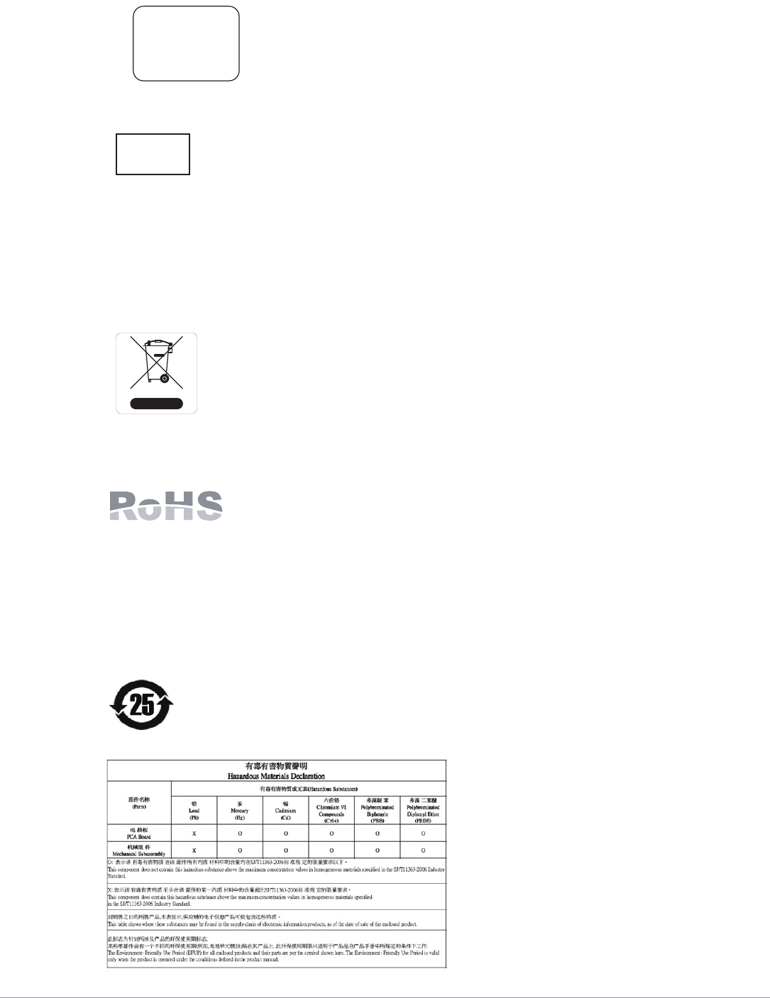
Waste of Electrical and Electronic Equipment
Aruba products at end of life are subject to separate collection and treatment in the EU
Member States, Norway, and Switzerland and therefore are marked with the symbol
shown at the left (crossed-out wheelie bin). The treatment applied at end of life of these
products in these countries shall comply with the applicable national laws of countries
implementing Directive 2002/96EC on Waste of Electrical and Electronic Equipment
(WEEE).
European Union RoHS
Aruba products also comply with the EU Restriction of Hazardous Substances
Directive 2002/95/EC (RoHS). EU RoHS restricts the use of specific hazardous
materials in the manufacture of electrical and electronic equipment. Specifically,
restricted materials under the RoHS Directive are Lead (including Solder used in printed circuit
assemblies), Cadmium, Mercury, Hexavalent Chromium, and Bromine. Some Aruba products are subject to
the exemptions listed in RoHS Directive Annex 7 (Lead in solder used in printed circuit assemblies).
Products and packaging will be marked with the “RoHS” label shown at the left indicating conformance to
this Directive.
China RoHS
Aruba products also comply with China environmental declaration requirements and are
labeled with the “EFUP 25” label shown at the left.
TRA
REGISTERED No:
DEALER No:
DA0039425/10
ER0107431/13
OMAN - TRA
R/1539/13
D080134

Aruba MST200 Wireless Mesh Router | Installation Guide 23
This page is intentionally left blank.
© 2014 Aruba Networks, Inc. All rights reserved.
www.arubanetworks.com
1344 Crossman Avenue
Sunnyvale, California 94089
Phone: 408.227.4500
Fax 408.227.4550
24 Aruba MST200 Wireless Mesh Router | Installation Guide
Contacting Aruba Networks
Web Site Support
Main Site http://www.arubanetworks.com
Support Site https://support.arubanetworks.com
Software Licensing Site https://licensing.arubanetworks.com/login.php
Wireless Security Incident
Response Team (WSIRT)
http://www.arubanetworks.com/support/wsirt.php
Support Emails
Americas and APAC support@arubanetworks.com
EMEA emea.support@arubanetworks.com
WSIRT Email
Please email details of any security
problem found in an Aruba product.
wsirt@arubanetworks.com
Telephone Support
Aruba Corporate +1 (408) 227-4500
FAX +1 (408) 227-4550
Support
United States 800-WI-FI-LAN (800-943-4526)
Universal Free Phone Service Number
(UIFN): Australia, Canada, China,
France, Germany, Hong Kong, Ireland,
Israel, Japan, Korea, Singapore, South
Africa, Taiwan, and the UK.
+800-4WIFI-LAN (+800-49434-526)
All Other Countries +1 (408) 754-1200