Hewlett Packard Enterprise WA2620EAGN Wireless LAN Access Point User Manual
Hewlett-Packard Company Wireless LAN Access Point
UserManual.wiki
>
Hewlett Packard Enterprise
>
WA2620EAGN User Manual
>
User's manual_new
Contents
1.
User's manual_new
2.
Users manual new
User's manual_new
Users manual new
Navigation menu
Upload a User Manual
Namespaces
Wiki Guide
HTML
PDF
Info
Views
User Manual
Discussion / Help
Navigation


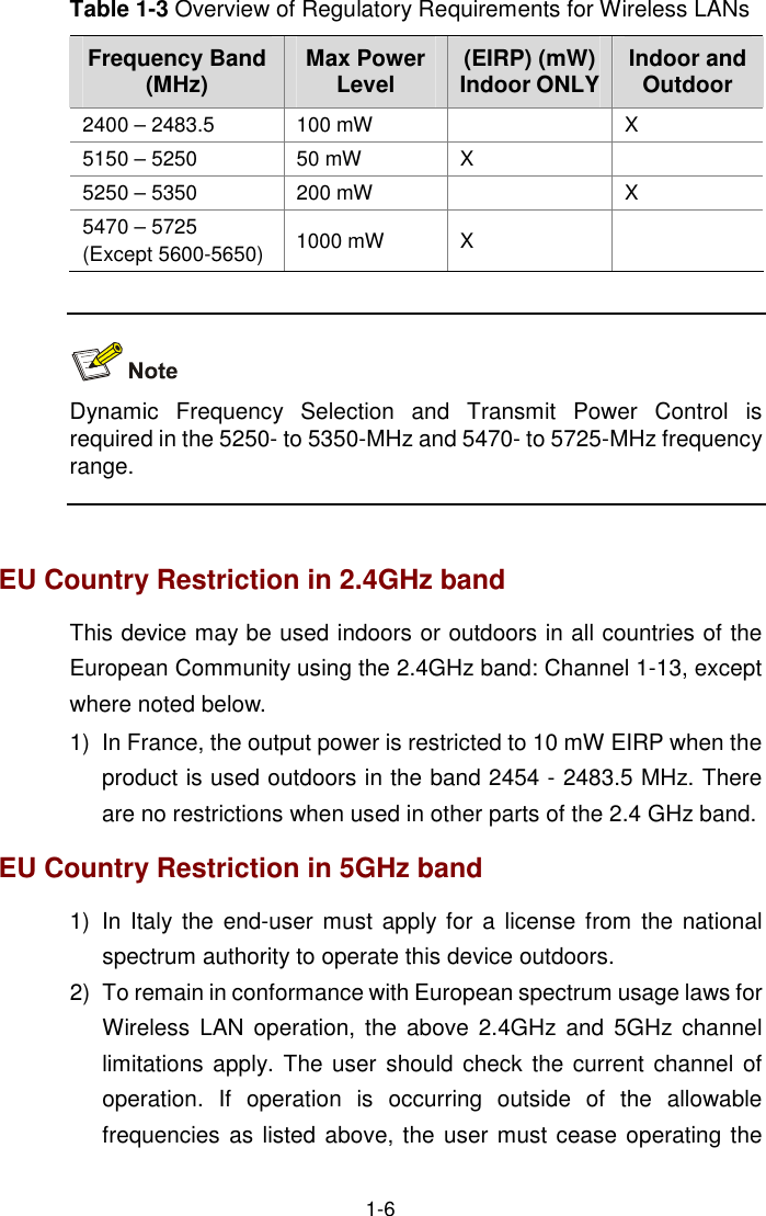
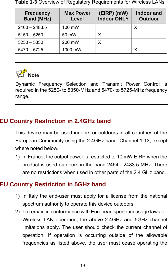
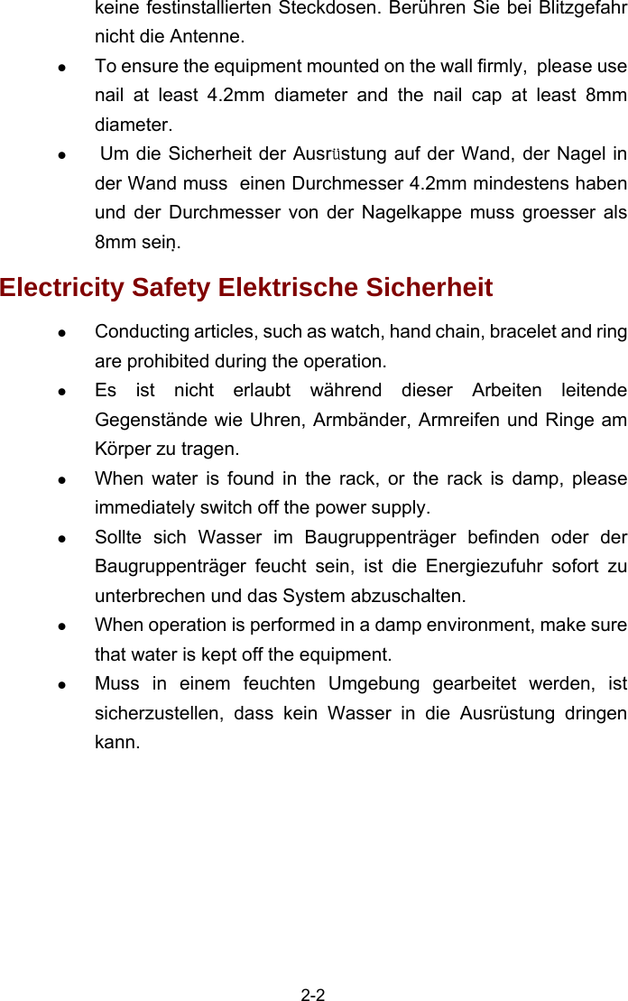
![Convention Description Means a complementary description. Obtaining Documentation You can access the most up-to-date H3C product documentation on the World Wide Web at this URL: http://www.h3c.com. The following are the columns from which you can obtain different categories of product documentation: [Products & Solutions]: Provides information about products and technologies. [Technical Support & Document > Technical Documents]: Provides several categories of product documentation, such as installation, operation, and maintenance. Documentation Feedback You can e-mail your comments about product documentation to info@h3c.com. We appreciate your comments. Environmental Protection This product has been designed to comply with the requirements on environmental protection. For the proper storage, use and disposal of this product, national laws and regulations must be observed.](https://usermanual.wiki/Hewlett-Packard-Enterprise/WA2620EAGN.User-s-manual-new/User-Guide-1211971-Page-4.png)


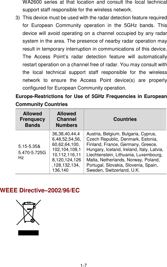
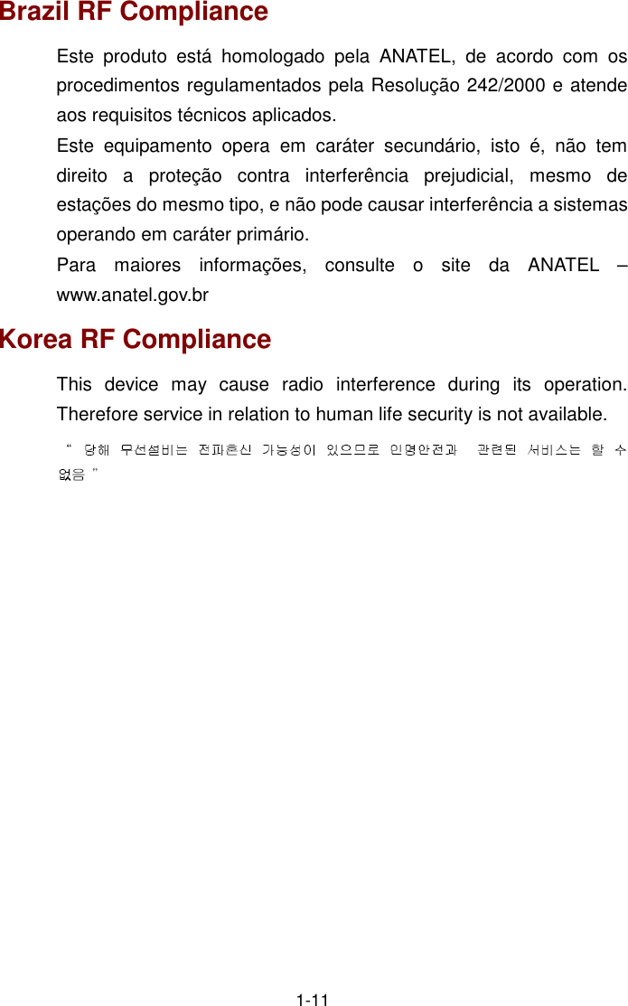
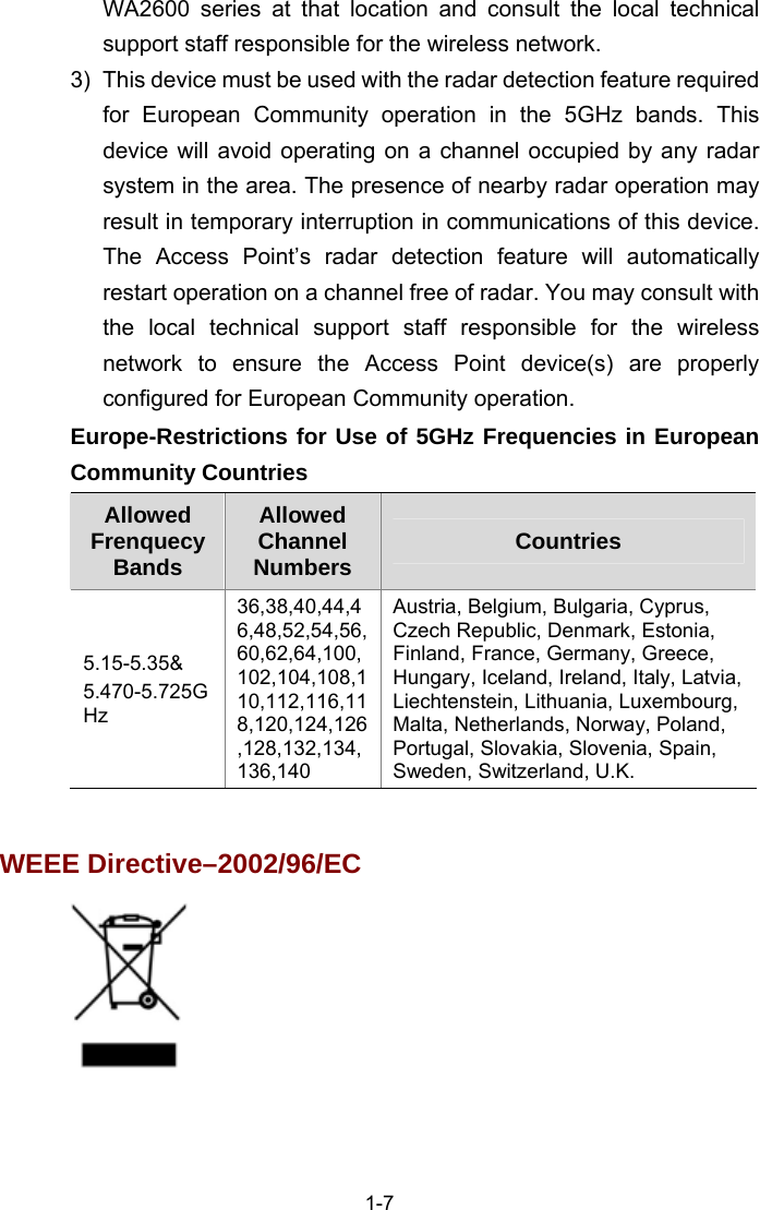
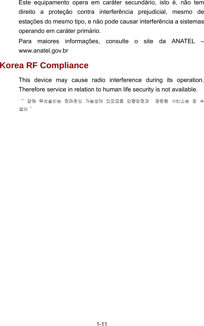
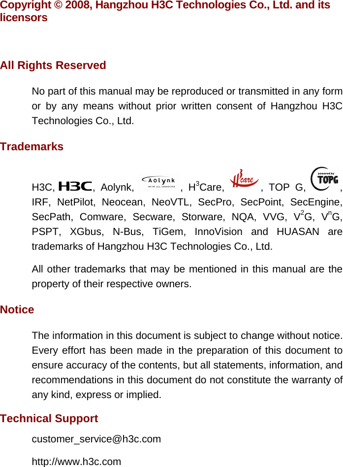
![1-3 EU Compliance information CE Marking Equipment may be operated in the following country: AT BE CY CZ DK EE FI FR DE GR HU IE IT LV LT LU MT NL PL PT SK SI ES SE GB IS LI NO CH BG RO TR 1) Select the country in which the product is installed to ensure product operation is in compliance with local regulations. For information on how to select the country, refer to the “Wireless Configuration Command” module in H3C Wireless Control Manager Command Manual. 2) Intended use: IEEE 802.11a/b/g and 802.11n Draft 2.0. 3) This product must maintain a minimum body to antenna distance of 20cm.Under these conditions this product will meet the Basic Restriction limits of 1999/519/EC(Council Recommendation of 12 July 1999 on the limitation of exposure of the general public to electromagnetic fields(0Hz-300GHz). R&TTE declaration statements: Česky [Czech]H3C Coporation tímto prohlašuje, že tento RLAN device je ve shodě se základními požadavky a dalšími příslušnými ustanoveními směrnice 1999/5/ES. Dansk [Danish] Undertegnede H3C Corporation erklærer herved, at følgende udstyr RLAN device overholder de væsentlige krav og øvrige relevante krav i direktiv 1999/5/EF.](https://usermanual.wiki/Hewlett-Packard-Enterprise/WA2620EAGN.User-s-manual-new/User-Guide-1211971-Page-36.png)
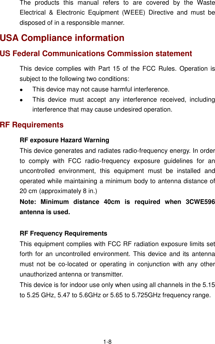
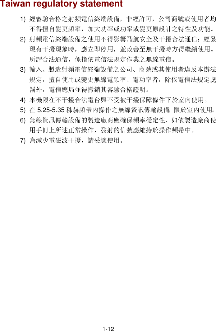
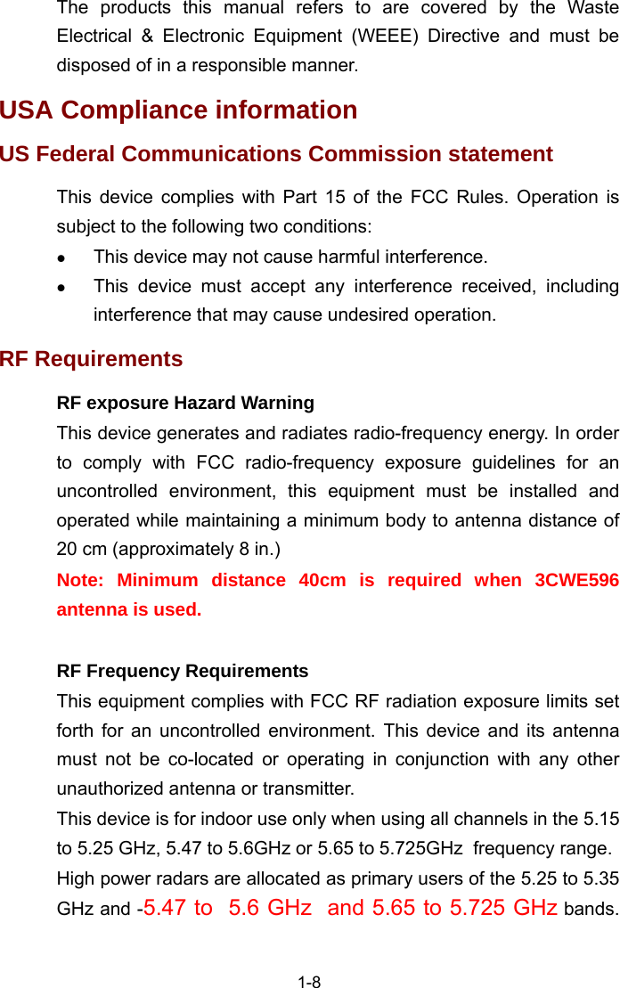
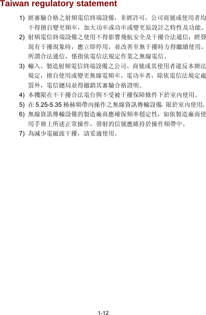
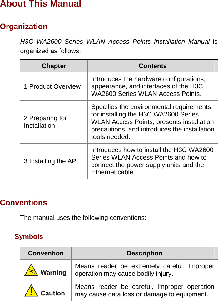
![1-4 Deutsch [German] Hiermit erklärt H3C Corporation, dass sich das Gerät RLAN device in Übereinstimmung mit den grundlegenden Anforderungen und den übrigen einschlägigen Bestimmungen der Richtlinie 1999/5/EG befindet. Eesti [Estonian] Käesolevaga kinnitab H3C Corporation seadme RLAN device vastavust direktiivi 1999/5/EÜ põhinõuetele ja nimetatud direktiivist tulenevatele teistele asjakohastele sätetele. English Hereby, H3C Corporation, declares that this RLAN device is in compliance with the essential requirements and other relevant provisions of Directive 1999/5/EC. Español [Spanish] Por medio de la presente H3C Corporation declara que el RLAN device cumple con los requisitos esenciales y cualesquiera otras disposiciones aplicables o exigibles de la Directiva 1999/5/CE. Ελληνική [Greek] ΜΕ ΤΗΝ ΠΑΡΟΥΣΑ H3C Corporation ΔΗΛΩΝΕΙ ΟΤΙ RLAN device ΣΥΜΜΟΡΦΩΝΕΤΑΙ ΠΡΟΣ ΤΙΣ ΟΥΣΙΩΔΕΙΣ ΑΠΑΙΤΗΣΕΙΣ ΚΑΙ ΤΙΣ ΛΟΙΠΕΣ ΣΧΕΤΙΚΕΣ ΔΙΑΤΑΞΕΙΣ ΤΗΣ ΟΔΗΓΙΑΣ 1999/5/ΕΚ. Français [French] Par la présente H3C Corporation déclare que l'appareil RLAN device est conforme aux exigences essentielles et aux autres dispositions pertinentes de la directive 1999/5/CE. Italiano [Italian] Con la presente H3C Corporation dichiara che questo RLAN device è conforme ai requisiti essenziali ed alle altre disposizioni pertinenti stabilite dalla direttiva 1999/5/CE. Latviski [Latvian] Ar šo H3C Corporation deklarē, ka RLAN device atbilst Direktīvas 1999/5/EK būtiskajām prasībām un citiem ar to saistītajiem noteikumiem. Lietuvių [Lithuanian] Šiuo H3C Corporation deklaruoja, kad šis RLAN device atitinka esminius reikalavimus ir kitas 1999/5/EB Direktyvos nuostatas. Nederlands [Dutch] Hierbij verklaart H3C Corporation dat het toestel RLAN device in overeenstemming is met de essentiële eisen en de andere relevante bepalingen van richtlijn 1999/5/EG. Malti [Maltese]Hawnhekk, H3C Corporation, jiddikjara li dan RLAN device jikkonforma mal-ħtiġijiet essenzjali u ma provvedimenti oħrajn relevanti li hemm fid-Dirrettiva 1999/5/EC.](https://usermanual.wiki/Hewlett-Packard-Enterprise/WA2620EAGN.User-s-manual-new/User-Guide-1211971-Page-37.png)
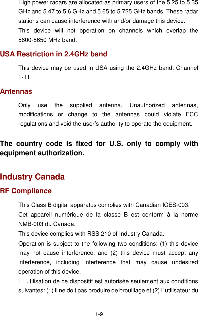
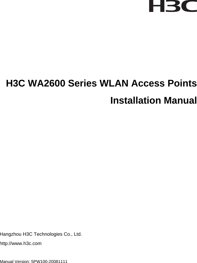
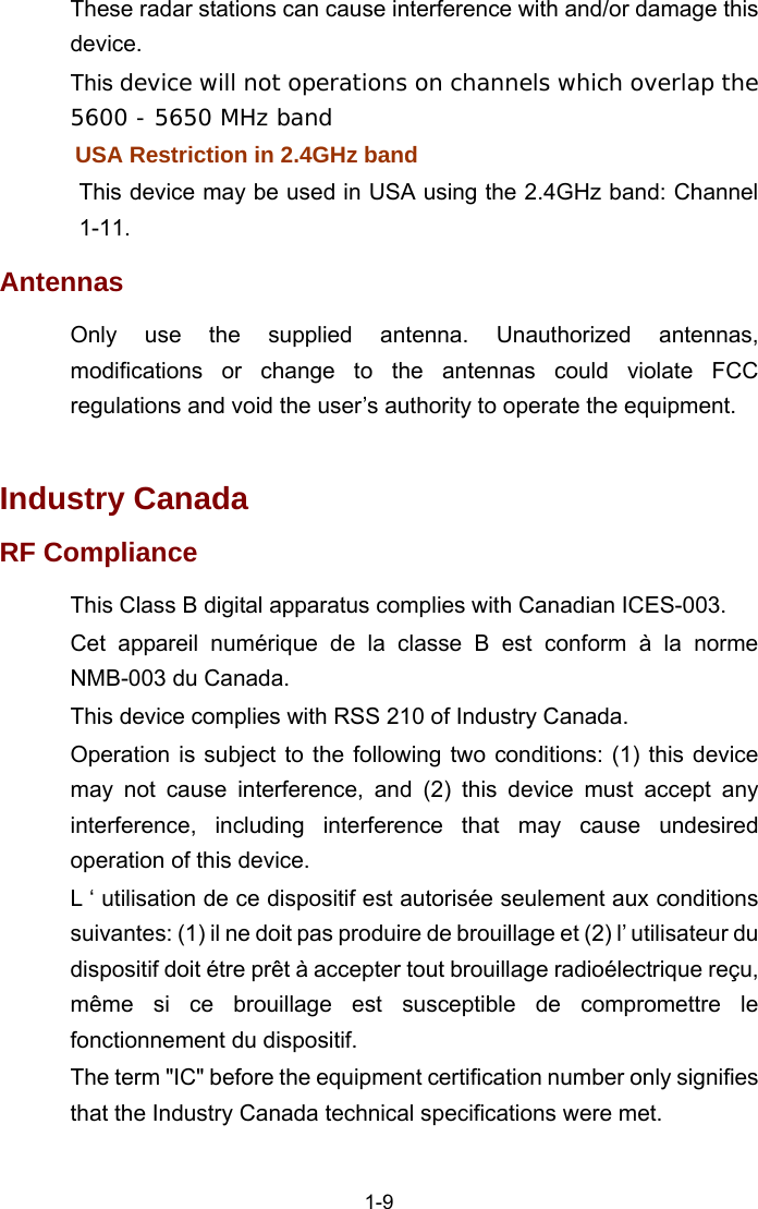
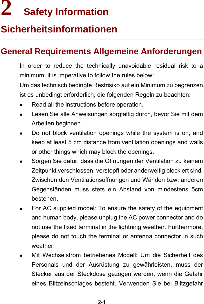
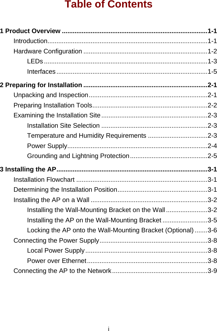
![1-5 Magyar [Hungarian] Alulírott, H3C Corporation nyilatkozom, hogy a RLAN device megfelel a vonatkozó alapvetõ követelményeknek és az 1999/5/EC irányelv egyéb elõírásainak. Polski [Polish]Niniejszym H3C Corporation oświadcza, że RLAN device jest zgodny z zasadniczymi wymogami oraz pozostałymi stosownymi postanowieniami Dyrektywy 1999/5/EC. Português [Portuguese] H3C Corporation declara que este RLAN device está conforme com os requisitos essenciais e outras disposições da Directiva 1999/5/CE. Slovensko [Slovenian] H3C Corporation izjavlja, da je ta RLAN device v skladu z bistvenimi zahtevami in ostalimi relevantnimi določili direktive 1999/5/ES. Slovensky [Slovak] H3C Corporation týmto vyhlasuje, že RLAN device spĺňa základné požiadavky a všetky príslušné ustanovenia Smernice 1999/5/ES. Suomi [Finnish] H3C Corporation vakuuttaa täten että RLAN device tyyppinen laite on direktiivin 1999/5/EY oleellisten vaatimusten ja sitä koskevien direktiivin muiden ehtojen mukainen. Svenska [Swedish] Härmed intygar H3C Corporation att denna RLAN device står I överensstämmelse med de väsentliga egenskapskrav och övriga relevanta bestämmelser som framgår av direktiv 1999/5/EG. Íslenska [Icelandic] Hér með lýsir H3C Corporation yfir því að RLAN device er í samræmi við grunnkröfur og aðrar kröfur, sem gerðar eru í tilskipun 1999/5/EC. Norsk [Norwegian] H3C Corporation erklærer herved at utstyret RLAN device er i samsvar med de grunnleggende krav og øvrige relevante krav i direktiv 1999/5/EF. A copy of the signed Declaration of Conformity can be downloaded from: http://www.h3c.com/portal/Technical_Documents http://support.3com.com/doc/H3C_WA26XXE-AGN_EU_DOC.pdf](https://usermanual.wiki/Hewlett-Packard-Enterprise/WA2620EAGN.User-s-manual-new/User-Guide-1211971-Page-38.png)

![Convention Description Means a complementary description. Obtaining Documentation You can access the most up-to-date H3C product documentation on the World Wide Web at this URL: http://www.h3c.com. The following are the columns from which you can obtain different categories of product documentation: [Products & Solutions]: Provides information about products and technologies. [Technical Support & Document > Technical Documents]: Provides several categories of product documentation, such as installation, operation, and maintenance. Documentation Feedback You can e-mail your comments about product documentation to info@h3c.com. We appreciate your comments. Environmental Protection This product has been designed to comply with the requirements on environmental protection. For the proper storage, use and disposal of this product, national laws and regulations must be observed.](https://usermanual.wiki/Hewlett-Packard-Enterprise/WA2620EAGN.Users-manual-new/User-Guide-1257170-Page-4.png)


![1-3 EU Compliance information CE Marking Equipment may be operated in the following country: AT BE CY CZ DK EE FI FR DE GR HU IE IT LV LT LU MT NL PL PT SK SI ES SE GB IS LI NO CH BG RO TR 1) Select the country in which the product is installed to ensure product operation is in compliance with local regulations. For information on how to select the country, refer to the “Wireless Configuration Command” module in H3C Wireless Control Manager Command Manual. 2) Intended use: IEEE 802.11a/b/g and 802.11n Draft 2.0. 3) This product must maintain a minimum body to antenna distance of 20cm.Under these conditions this product will meet the Basic Restriction limits of 1999/519/EC(Council Recommendation of 12 July 1999 on the limitation of exposure of the general public to electromagnetic fields(0Hz-300GHz). R&TTE declaration statements: Česky [Czech] H3C Coporation tímto prohlašuje, že tento RLAN device je ve shodě se základními požadavky a dalšími příslušnými ustanoveními směrnice 1999/5/ES. Dansk [Danish] Undertegnede H3C Corporation erklærer herved, at følgende udstyr RLAN device overholder de væsentlige krav og øvrige relevante krav i direktiv 1999/5/EF.](https://usermanual.wiki/Hewlett-Packard-Enterprise/WA2620EAGN.Users-manual-new/User-Guide-1257170-Page-36.png)
![1-4 Deutsch [German] Hiermit erklärt H3C Corporation, dass sich das Gerät RLAN device in Übereinstimmung mit den grundlegenden Anforderungen und den übrigen einschlägigen Bestimmungen der Richtlinie 1999/5/EG befindet. Eesti [Estonian] Käesolevaga kinnitab H3C Corporation seadme RLAN device vastavust direktiivi 1999/5/EÜ põhinõuetele ja nimetatud direktiivist tulenevatele teistele asjakohastele sätetele. English Hereby, H3C Corporation, declares that this RLAN device is in compliance with the essential requirements and other relevant provisions of Directive 1999/5/EC. Español [Spanish] Por medio de la presente H3C Corporation declara que el RLAN device cumple con los requisitos esenciales y cualesquiera otras disposiciones aplicables o exigibles de la Directiva 1999/5/CE. Ελληνική [Greek] ΜΕ ΤΗΝ ΠΑΡΟΥΣΑ H3C Corporation ∆ΗΛΩΝΕΙ ΟΤΙ RLAN device ΣΥΜΜΟΡΦΩΝΕΤΑΙ ΠΡΟΣ ΤΙΣ ΟΥΣΙΩ∆ΕΙΣ ΑΠΑΙΤΗΣΕΙΣ ΚΑΙ ΤΙΣ ΛΟΙΠΕΣ ΣΧΕΤΙΚΕΣ ∆ΙΑΤΑΞΕΙΣ ΤΗΣ Ο∆ΗΓΙΑΣ 1999/5/ΕΚ. Français [French] Par la présente H3C Corporation déclare que l'appareil RLAN device est conforme aux exigences essentielles et aux autres dispositions pertinentes de la directive 1999/5/CE. Italiano [Italian] Con la presente H3C Corporation dichiara che questo RLAN device è conforme ai requisiti essenziali ed alle altre disposizioni pertinenti stabilite dalla direttiva 1999/5/CE. Latviski [Latvian] Ar šo H3C Corporation deklarē, ka RLAN device atbilst Direktīvas 1999/5/EK būtiskajām prasībām un citiem ar to saistītajiem noteikumiem. Lietuvių [Lithuanian] Šiuo H3C Corporation deklaruoja, kad šis RLAN device atitinka esminius reikalavimus ir kitas 1999/5/EB Direktyvos nuostatas. Nederlands [Dutch] Hierbij verklaart H3C Corporation dat het toestel RLAN device in overeenstemming is met de essentiële eisen en de andere relevante bepalingen van richtlijn 1999/5/EG. Malti [Maltese] Hawnhekk, H3C Corporation, jiddikjara li dan RLAN device jikkonforma mal-ħtiġijiet essenzjali u ma provvedimenti oħrajn relevanti li hemm fid-Dirrettiva 1999/5/EC.](https://usermanual.wiki/Hewlett-Packard-Enterprise/WA2620EAGN.Users-manual-new/User-Guide-1257170-Page-37.png)
![1-5 Magyar [Hungarian] Alulírott, H3C Corporation nyilatkozom, hogy a RLAN device megfelel a vonatkozó alapvetõ követelményeknek és az 1999/5/EC irányelv egyéb elõírásainak. Polski [Polish] Niniejszym H3C Corporation oświadcza, że RLAN device jest zgodny z zasadniczymi wymogami oraz pozostałymi stosownymi postanowieniami Dyrektywy 1999/5/EC. Português [Portuguese] H3C Corporation declara que este RLAN device está conforme com os requisitos essenciais e outras disposições da Directiva 1999/5/CE. Slovensko [Slovenian] H3C Corporation izjavlja, da je ta RLAN device v skladu z bistvenimi zahtevami in ostalimi relevantnimi določili direktive 1999/5/ES. Slovensky [Slovak] H3C Corporation týmto vyhlasuje, že RLAN device spĺňa základné požiadavky a všetky príslušné ustanovenia Smernice 1999/5/ES. Suomi [Finnish] H3C Corporation vakuuttaa täten että RLAN device tyyppinen laite on direktiivin 1999/5/EY oleellisten vaatimusten ja sitä koskevien direktiivin muiden ehtojen mukainen. Svenska [Swedish] Härmed intygar H3C Corporation att denna RLAN device står I överensstämmelse med de väsentliga egenskapskrav och övriga relevanta bestämmelser som framgår av direktiv 1999/5/EG. Íslenska [Icelandic] Hér með lýsir H3C Corporation yfir því að RLAN device er í samræmi við grunnkröfur og aðrar kröfur, sem gerðar eru í tilskipun 1999/5/EC. Norsk [Norwegian] H3C Corporation erklærer herved at utstyret RLAN device er i samsvar med de grunnleggende krav og øvrige relevante krav i direktiv 1999/5/EF. A copy of the signed Declaration of Conformity can be downloaded from: http://www.h3c.com/portal/Technical_Documents http://support.3com.com/doc/H3C_WA26XXE-AGN_EU_DOC.pdf](https://usermanual.wiki/Hewlett-Packard-Enterprise/WA2620EAGN.Users-manual-new/User-Guide-1257170-Page-38.png)